1. Introduction
The present experimental study is in line with the EU-defined energy and environmental objectives, which emphasizes the need to increase by 27% the use of renewable energy sources (biomass, hydropower, geothermal, solar, wind and marine) for energy production, to enhance energy efficiency by 27% and to reduce greenhouse gas emissions into the environment by 40% by 2030 [
1]. Among all renewable energy sources, plant biomass is recommended as a source of CO
2- neutral energy, so confirming that the combustion of biomass produces an amount of CO
2 comparable to that this absorbed at photosynthesis, thus reducing greenhouse gas emissions and the impact of energy producers on global warming [
2]. However, different types of biomass, for example, wood waste, agriculture residues (straw) and partially bio-decomposed plant biomass (peat), which can be used for energy production, have a dissimilar structure, bulk density, elemental and chemical composition. Therefore, to provide a reliable energy production from plant biomass, the plant biomass should be shaped as pellets or briquettes with controllable density, structure, elemental and chemical composition. Moreover, to convert the biomass into useful forms of energy, thermo-chemical and biochemical conversion of biomass is required [
3].
Nowadays, the analysis of the consumption of renewable fuel for energy production for district heating has already revealed the seasonal wood pellets shortage [
4]. Therefore, the wider use of alternative biomass fuels, such as agriculture residues (rape straw, wheat straw, rice husk, etc.), must be considered. The feasibility of straw for energy production is limited due to its relatively low heating value and energy density, high nitrogen, moisture and ash content in the biomass [
5], as well as due to the ash agglomeration and formation of health harmful polycyclic aromatic hydrocarbons naphthalene and phenanthrene emissions during the combustion of straw [
4]. To minimize the negative effects of straw on the heat production and composition of the products, co-combustion/co-firing of straw with different types of solid fuels (coal, wood and peat) is preferable. The results of a systematic study of biomass co-firing give evidence that a promising way to ensure the most efficient use of straw for energy production with no harmful effect on the environment is co-combustion of straw with coal [
6]. Therefore, co-firing of wheat straw with granulated wood and peat biomass is studied and analyzed with the aim of obtaining improved main characteristics of the straw thermo-chemical conversion [
7,
8]. By analogy with the effect of straw co-firing with coal [
9], the thermal interaction between the components when straw is co-fired with wood or peat pellets results in enhanced thermal decomposition of the biomass pellet mix, in a faster and more intensive release of the combustible volatiles, their faster ignition and faster formation of the flame reaction zone, which enhances the fuel burnout. Co-firing of straw also increases the heat output from the device, the produced heat per mass of burned pellet mix and the volume fraction of CO
2, decreasing along the air excess in the flue gases. Previous experimental studies show [
7,
8,
9] that the influence of the straw co-firing on the main combustion characteristics strongly depends on the straw share in the pellet mix, indicating the most effective improvement of the main combustion characteristics when the straw share is about 20–30%. Furthermore, the thermo-chemical conversion of straw depends not only on the straw share and mixture composition, but also depends on the type of air supply in the unit responsible for mixing of the combustible volatiles with air. To obtain better mixing of air with the combustible volatiles, improved combustion conditions and the reduced emission of CO and NOx pollutants, the use of swirling airflow is preferable [
10,
11], which even at a low swirling number (S < 0.6) enhances the reverse flow formation and recirculation of the products with the enhanced mixing of the air and combustible volatiles and enhanced burnout of volatiles.
The results of preliminary studies suggest that additional improvement of the combustion characteristics, heat production and composition of emissions at co-firing of straw with solid fuels can be achieved using the DC electric field effects on the flame [
12,
13]. The electric field effects on flames can be related to the electric field-induced ion wind formation [
14] promoting the processes of field-induced heat/mass transfer in a field direction with direct influence on the flame shape, the local variations in the rate of reactions, the amount of produced heat and the composition of products [
15,
16]. The applicability of the electric field effects on flames for the control of the heat production and composition of emissions is confirmed by the industrial experiments [
17].
With account of applicability of electric field for the control of the main characteristics of the combustion systems, the main goal of the present research is to assess the key factors which influence the development of combustion dynamics during co-firing of wheat straw with softwood or peat pellets, if the electric field is applied to the flame base. In addition, the paper tends to validate the results of the experimental study by means of numerical simulation and mathematical modelling of the field effects on the development of combustion dynamics at co-firing solid fuel mixtures.
2. Experimental Device and Methods
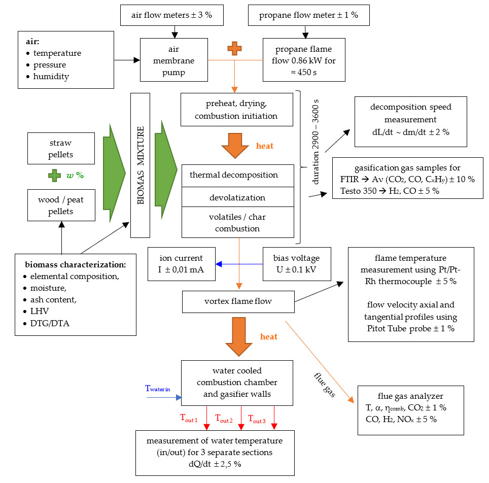
To study the effects of the wheat straw co-firing with biomass pellets of different origin (wood or peat), a batch-size pilot setup with a heat output up to 4 kW has been developed. The experimental setup (
Figure 1) consists of a cylindrical 88 Ø × 250 mm biomass gasifier (1), a propane burner (2), a primary air supply (3), a secondary swirling air supply (4) and two cylindrical 88 Ø × 600 mm water-cooled combustion chamber sections (5) and an axially inserted electrode (6).
The gasifier was filled up to the propane supply nozzle with a discrete portion of a mixture of wheat straw and wood or peat pellets (430–550 g). The wheat straw share in the pellet mix varied from 10 to 100%. The thermal decomposition of biomass pellets was initiated and sustained up to 450 s by an external heat source–propane flame flow with the average heat power 0.86 kW and was switched off after an ignition of volatiles and the formation of self-sustaining thermochemical conversion of biomass pellets, which occurs at 400–500 s. The thermal decomposition of the biomass mixture in the gasifier developed in the fuel-rich conditions (air excess ratio <0.5) and resulted in formation of the axial flow of combustible volatiles (CO, H
2, C
2H
2, C
2H
4, CH
4, etc.) at the flame base. The thermochemical conversion of the biomass mixture lasted about 2600 s if straw is co-fired with wood pellets and about 3600 s if straw is co-fired with peat. The schematic diagram which describes the experiment is available at
Figure S1.
The primary air (3), passing through the biomass layer at the average flow rate 30 L·min−1, initiated an axial flow of the volatiles and sustained the char surface oxidation. The secondary swirling airflow, supplied to the bottom of the combustor at the average airflow rate 40 l·min−1, supported the combustion of the volatiles. The air supply flowrate was estimated using Testo 6441 flowmeters (Testo SE & Co. KGaA, Lenzkirch, Germany) with an accuracy ± 3%.
The diagnostic tools (thermocouples, gas-sampling probes, Pitot tube) were introduced through the orifices (7) into the flame reaction zone to make local measurements of the flame temperature, composition of the flue gas and of the axial and tangential components of the flow velocity.
The DC electric field effect on the thermo-chemical conversion of biomass mixtures, the development of combustion dynamics and the composition of emissions were studied using the axially inserted positively biased electrode. The electrode was a 3 mm diameter nichrome wire rod with 100 mm of non-insulated length. The electrode was introduced through the biomass layer upward to the flame reaction zone. The bias voltage of the electrode was switched in after the switch off of the additional heat supply by propane flame and was varied from 0.6 kV up to 1.8 kV, the ion current in the space between the positive electrode and the grounded walls of the combustion chamber was limited to 7 mA at 248 kΩ resistance to avoid the formation of discharge.
The experimental study of the biomass mixture thermal decomposition involves complex time-dependent measurements of the biomass height (L) in the gasifier (dL/dt, mm·s−1) using the moving rod with a pointer. From the measurements of dL/dt and volume density of the biomass mixture, the mixture mass loss rate (dm/dt, g·s−1) was estimated with the accuracy ± 2%. The composition of the volatiles produced at the thermal decomposition of the biomass mixtures was measured at the gasifier outlet by the FTIR spectroscopy method. Gas samples of 50 ml were extracted at a 50 s time interval and analyzed using a Varian Cary 640 spectrometer (Agilent Technologies, Inc., Santa Clara, CA, USA ) in the MIR spectral range for CO2 (668 cm−1), CO (average of 2115 and 2169 cm−1), C2H2 (729 cm−1), C2H4 (949 cm−1), and CH4 (3017 cm−1). Additionally, at the gasifier outlet, CO and H2 were measured by a Testo 350 gas analyzer.
The local measurements of the axial (u) and tangential (w) flow velocity components were made using a Pitot tube and a Testo 435 flowmeter, providing continuous online data monitoring with an accuracy of ± 1%. The air and gas flow swirl number (S, dimensionless), was calculated from the data of the radial measurements of the axial and tangential flow velocity profiles at about 130 mm above the secondary air supply as follows [
10]:
where:
wav,
uav—the average values of the tangential and axial velocity components, (m·s
−1).
A Pico logger (Pico Technology, Cambridgeshire, UK) recorded the local temperature data from the Pt/Pt-Rh thermocouples with an accuracy of ±5% providing data online registration. The local measurements of the flue gas composition, i.e., the mass fraction of unburned volatiles (CO, H
2), the volume fraction of the main combustion product (CO
2), the mass fraction of NO
x pollutant, as well as the combustion efficiency (η
comb) and the air excess ratio (α) were made by the Testo 350 gas analyzer. In accordance with the Testo 350 specifications, the O
2, CO
2 volume fraction was measured with an accuracy of ±1% and the mass fraction of CO, H
2 and NO
x with an accuracy of about ±5%. The extended description of the measurement data acquisition is at the
supplementary materials.
The calorimetric measurements of the cooling water flow involve joint measurements of the cooling water mass flow, which was measured with the accuracy ± 2.5% and of the temperature, which were made with the accuracy ±1% by AD 560 thermo-sensors (Analog Devices, Inc., Norwood, MA, USA), along with online data registration by a Data Translation DT9805 data acquisition module (Data Translation GmbH, Bietigheim-Bissingen, Germany) using Quick DAQ software.
The combustion of the volatiles developed at the average air excess ratio α ≈ 1.5 in the flame reaction zone at the average value of the inlet airflow swirl number S ≈ 0.7 (without the electric field applied) which is responsible for the mixing of the axial flow of volatiles with the secondary swirling airflow.
The commercially available wheat straw, softwood (wood working waste—is the mixture of different biological species: pine, spruce, etc.) biomass pellets used for the co-firing studies originated from Latvia, and the bog peat pellets originated from Skrebeļu bog (Latvia).
The elemental composition (C, H, N content) of softwood, wheat straw, bog peat biomass types were measured using the Vario Macro elemental analyzer (Elementar Analysensysteme GmbH, Langenselbold, Germany) and analyzed according to the LVS EN 15104:2011 standard. The ash content was measured as a residue after the treatment at 830 ± 10 K in an ELF 11/6B furnace (Carbolite Gero Limited, Parsons Ln, Hope Valley, UK) in accordance with the LVS EN 14775:2010 standard [
18]. The higher heating value (HHV) of the pellets were calculated by the regression equation proposed by Friedl et al. [
19]:
where the elemental composition (C—carbon content, H—hydrogen content, N—nitrogen content and W—moisture) of softwood, wheat straw and peat biomass (
Table 1).
Lower heating value (LHV) of the pellets were calculated using the regression equation [
20]:
The thermal decomposition of the biomass pellets and their mixtures was studied in the 300–900 K temperature range by differential thermogravimetric and thermal analysis (TGA/DTA) in an oxidative atmosphere (50 ml·min
−1 air flowrate) using a Star System TGA/DTA 851e (Metter Toledo, Columbus, OH, USA) at a heating rate of 10 K·min
−1 [
18]. The main elemental characteristics of the biomass pellets are summarized in
Table 1.
The main elemental characteristics of the biomass pellets (
Table 1) show the highest carbon content as well as the highest LHV for peat, hence, it has also the highest moisture content among the studied biomass samples. Furthermore, peat has the lowest content of oxygen due to the partial bio-decomposition processes occurring in the bog land environment, therefore, it may require more air oxygen to sustain the combustion process.
Although the wheat straw total nitrogen content is very high compared to softwood, bog peat also has a high content of nitrogen in its elemental composition, which may evidence of the peat botanical composition characterized mostly by sphagnum moss, sedge and other acid-water plants [
21].
3. Results and Discussion
In order to determine the electric field effects on the thermo-chemical conversion of wheat straw mixtures by co-firing wheat straw with wood or with peat pellets, firstly, the effect of wheat straw share in the mixture (wt.%) on the thermal decomposition of the mixture and heat release was studied.
The TGA and DTA analysis results show that the variations of the straw mass share in the mixtures correlate with the complex variations of the volatiles and char formation and their combustion, depending on the chemical composition of the components (
Figure 2a–d). As follows from
Figure 2a,b, the most intensive mass loss (1.4 mg·min
−1), due to the formation of volatiles, with the most pronounced exothermic heat effect on the thermal decomposition at 598 K was achieved for the softwood samples, which have the highest content of holocellulose (hemicellulose and cellulose together) 75–80% [
22]. The less intensive formation of volatiles was observed for the peat samples (0.4 mg·min
−1 at 578 K), which have the lowest content of polysaccharides (10–30% [
23]), however, the volatile carbon content can achieve ≈58% [
5]. The middle level of the volatile formation (1.1 mg·min
−1) was observed for the wheat straw samples with the highest content of holocellulose (58–60%) [
24] and with the lowest thermal decomposition temperature (566 K).
The second peak of the mass loss rate at 665 K on the TGA curve of the wheat straw sample is comparable to the one at the second thermal decomposition stage of the bog peat under analysis (
Figure 2b), however the third sharp peak at ≈ 710 K could match the second stage of wood thermal decomposition (
Figure 2a).
The DTA analysis, when heating the mixtures in an oxidative atmosphere, also suggests that the combustion of volatiles initiates an intensive heat release at temperatures about 590–620 K. The second pronounced thermal conversion stage at T > 670 K corresponds to the heat release at a less intensive conversion of the aromatic compounds of lignin for wood and straw [
25,
26] and at the conversion of partially bio-degraded lignin and humic acids for peat [
21] (
Figure 2c,d).
For the mixtures of straw and wood with 10–30% mass fraction of straw, the heat release corresponds to the wood DTA curve, but has no sharp peaks. The DTA analysis of straw-peat mixtures indicates an increase in heat release at the volatiles combustion stage, due to the higher content of polysaccharides in wheat straw, and at the char combustion stage, which may be due to the differences in components of which the char is formed (
Figure 2c,d).
The combustion of biomass discrete portions in the experimental setup allows to eventually analyze different stages of the biomass thermal decomposition and combustion of volatiles. The complete thermo-chemical conversion of discrete portions of wheat straw, softwood and their mixtures lasts about 2900 s, whereas the thermo-chemical conversion of peat and its mixtures with straw takes up to 3600 s (
Figure 3a,b). During this period the intensive biomass heating and devolatization processes stimulate the primary flaming combustion of the volatiles with transition to the self-sustained volatiles combustion (at 800–900 s for straw/wood and 900–1000 s for straw/peat), when the exothermic reactions of the thermo-chemical conversion of combustible volatiles maintain a balance with the endothermic processes of biomass heating, dewatering and thermal decomposition.
The FTIR spectrum analysis of the CO formation at co-gasification of straw with wood or with peat pellets shows the formation of specific stages of their thermal decomposition. The primary stage of the biomass thermochemical conversion with transition from the endothermic biomass thermal decomposition to the exothermic ignition and flaming combustion of the volatiles lasts from 600 s up to 900 s for wood pellets, from 800 s to 1200 s for straw pellets, and from 800 s to 1400 s for peat pellets, when the flame temperature increases from the minimum value (about 600 K) to the maximum value—1000–1200 K (min-max). The next stage of the self-sustained combustion of volatiles at the thermo-chemical conversion of wood pellets lasts up to ≈1700 s; when co-firing straw with wood it takes up to ≈1800 s and up to ≈2300 s for peat and the flame temperature decreases from the maximum value to the end value of self-sustained combustion—about 800–900 K (max-end). The transition to the char combustion stage results in an enhanced formation of CO, whereas CH4 is no longer detected. For wood pellets, the transition to the char conversion stage occurs within the 1700 s to 2200 s time interval; for straw at t ≈ 1800–2300 s and for straw/wood mixtures at t ≈ 1800–2300 s. It should be noted that transition to char conversion stage results in a rapid decrease of the flame temperature to 550–650 K, which suggests the development of the endothermic processes, which is confirmed by a correlating increase of the mass fraction of CO and H2 in the products.
The kinetics of thermochemical conversion of different biomass types are caused by the specific elemental and chemical composition of pellets, but the most characteristic features of the combustion process of different biomass types can be specified. The intensive thermal decomposition of softwood may be explained by the higher heating value of wood pellets, which provides the faster balance between the exothermic and endothermic processes during the thermochemical conversion of pellets. The wheat straw thermochemical conversion is accompanied by the char/ash layer formation on the surface of the raw biomass, which gradually restricts the air access to the reaction zone. The bog peat thermal decomposition is delayed due to the relatively high density of its pellets, high moisture content and low volatiles content, which generally prevents the formation of the primary flaming combustion stage. Nevertheless, the thermochemical conversion of bog peat pellets is a stable and long-lasting process, which is developing with the reduced flame length due to the low content of volatile matter and high content of fixed carbon.
The thermochemical conversion of biomass pellets at co-firing of straw with wood or peat closely links to variations of the mass loss of the mixtures, depending on the mixture composition. During the primary stage of the flame formation (
t < 1000 s) increasing the mass fraction of straw in the mixture with wood pellets delays the formation and ignition of volatiles (
Figure 3a) decreasing to the minimum value the mass loss rate of the mixture (
Figure 4a). During the self-sustaining thermochemical conversion of the mixture (max-end) the inverse trend is observed. Increasing the mass fraction of straw in the mixture up to 30% causes the enhanced development of the exothermic reactions at thermo-chemical conversion of the mixture with an increase up to the peak value the mass loss rate of the mixture (
Figure 4a). Besides, to the minimum value decreases the mass fraction of combustible volatiles entering the combustor (
Figure 4c), which suggests the enhanced burnout of volatiles. Increasing the share of straw in the mixture above 30% promotes a decrease of the weight loss rate of the mixture, whereas increases the volume fraction of combustible volatiles in the flowing gas.
During co-firing of straw with peat increasing the mass fraction of straw in the mixture up to 30% causes the enhanced formation of volatiles (
Figure 3b) with a correlating increase up to the peak values the mass loss rate of the mixture and the average values of the volume fraction of combustible volatiles in the gas entering the combustor (
Figure 4b,d). Increasing the mass fraction of straw in the mixture above 30% promotes a decrease of the weight loss rate of the mixture with a correlating decrease of the volume fraction of combustible volatiles in the flowing gas.
The research results suggest that the thermal decomposition of the mixtures during co-firing of straw with wood or peat is influenced not only by the variations of the elemental composition and heating values of the components (
Table 1), but also by the thermal interaction between the components, which determine their thermo-chemical conversion and composition of the products (
Figure 5a,b). As follows from
Figure 5, the enhanced thermal decomposition of the mixture at co-firing of straw with wood or pellets correlates with an increase of the CO
2 volume fraction in the products and flue gas temperature up to peak values, if the mass share wt.% of straw in the mixture is about 30% and starts to decrease if the mass fraction of straw in the mixture exceeds and the further rise of the mixture thermal decomposition is limited by a linear decrease of its heating value. Moreover, with the 30% straw mass share wt.% in the mixture, its co-firing with wood reduces the NO
x mass fraction in the flue gas from 330 ppm to 200 ppm, whereas the straw co-firing with peat reduces the NO
x mass fraction from 290 ppm to 210 ppm. This confirms that the co-firing of straw with wood or with peat assures the cleaner heat production.
3.1. Electric Field Effect on the Thermal Decomposition and Combustion Characteristics When Co-Firing Straw with Wood or PEAT Pellets
From the results presented above it follows that co-firing of straw with wood or peat pellets allows the enhanced thermochemical conversion of the mixtures if the mass fraction of straw in the mixture is limited to 20–30%. To assess the potential for the additional improvement of the co-firing of the straw mixture with wood or peat, the electric field effects on the development of thermochemical conversion of the mixtures were studied and analyzed at the fixed mass fraction of straw in the mixture (30%).
When co-combusting straw and peat, the electric field induced variations of the main flame characteristics are determined by the formation of charged flame species, and by the field-induced transport of positive and negative gaseous species from the pyrolysis and reaction zones in the field direction. Elastic collisions between the ions and gaseous compounds result in a momentum transfer from charged particles (predominately positive ions) to neutral species, so enhancing their transport in the field direction and producing the so-called “ionic wind” phenomenon [
14] with a direct impact on the swirling flame shape and structure [
27,
28]. The ion wind formation is strongly influenced by the electric body force F = q·E determining the motion of charged flame species and advancing the heat and mass transfer of neutrals and chemical species. Therefore, to provide effective electric control of the main flame characteristics, it is necessary to apply the electric field to the flame area with a maximum ion density (q). It is generally assumed [
29] that the formation of positive ions in hydrocarbon flames can be related to the development of chemical ionization reactions between the flame components:
In general, the formation of ions at thermal decomposition of biomass pellets is a result of the consequent release of different hydrocarbons (C
xH
y). The measurements and analysis of the produced gases released at the thermal decomposition of biomass pellets (straw, peat and their mixtures) confirm the intensive formation of the combustible volatiles (H
2, CO) and hydrocarbon traces (C
2H
2, C
2H
4, CH
4), which are responsible for the formation of the flame reaction zone and primary flame ions [
12,
13]. The measurements of the radial and axial distributions of the flame ions prove that the most intensive formation of the flame ions occurs at the primary stage of flaming combustion (t < 1200 s). The peak value of the ion density (5–6)·10
17 m
−3 was observed at the bottom of the combustor (48–60 mm from the biomass surface), close to the flame axis (r/R = 0), where the axial flow of hydrocarbon traces rapidly mixes with the air accelerating the ion formation via the mechanism (4–6). Hence, to obtain the most intensive field-induced variations of the flame characteristics, the electric field must be applied to this part of the flame.
The 30% straw mass share wt.% added to the wood or peat mixture was chosen to investigate the potential of electric control of the combustion dynamics at co-firing straw with wood or peat, with the aim to provide a wide use of straw as a fuel for cleaner heat production, as observed when providing the electric control of the swirling propane flame flow [
15,
16,
28] and the electric field-induced body force enhances the evident variations of the flame shape and length determined by the field-induced variations of flow dynamics.
The complex measurements of the electric field effect on the formation of flow dynamics at co-firing of straw with wood or with peat pellets were provided for the positively bias voltage of the axially inserted electrode, which is inserted into the flame reaction zone at 130 mm from the secondary air supply nozzle (
Figure 1), where the average flame temperature approaches to 1350K. For the given configuration of the electrode the electric body force acts on the positive flame ions enhancing the processes of radial and reverse axial heat/mass transfer. As a result, to minimum value decreases the axial flow velocity, increasing the swirl intensity of secondary air and enhancing mixing of the reactants along the outside of the flame reaction zone (
Figure 6a,b). The field-induced decrease of the axial flow of combustible volatiles increases the residence time of the reactants in the flame reaction zone completing the burnout of the volatiles.
Besides, the field enhanced reverse axial heat mass transfer up to the biomass layer enhances heating and thermal decomposition of the biomass pellets increasing the biomass mass loss rates and the volume density of the volatiles at the gasifier outlet depending on the field-induced ion current (
Figure 7a,b).
With the 30% mass share of straw in the mixture and with increasing bias voltage of the positive electrode and the ion current in the space between the electrodes, the mixture mass loss rate tends to decrease during the primary stage of volatiles formation (400 s–max), when the electric field enhances the development of the endothermic processes of the thermal decomposition and it increases during the self-sustained burnout of the volatiles (max–end).
The field-enhanced thermal decomposition of the pellet mixtures correlates with the increased volume fraction of the volatiles at the gasifier outlet. The local decrease of the volume fraction of combustible volatiles at 1–3 mA ion current suggests that the field-enhanced reverse axial mass transfer initiates the enhanced mixing of the axial flow of volatiles with the secondary air-flow, thus enhancing the burnout of the volatiles (
Figure 8a,b).
As the field-enhanced decrease of the axial flow velocity determines the increase of the residence time of the reactants in the primary zone of flame formation completing combustion of volatiles, the heat power (P
selfsus) from the device at the self-sustained combustion stage increases by ~6–8% with the correlating increase of the total collected heat produced per mass of burned mixture (Q
sum) by ~10–12% (
Figure 9a–d).
Although the heat power of the device at the stage of self-sustained combustion keeps growing, the total produced heat per mass of burned solid fuel decreases after reaching its peak value at I = 1.9 mA at straw/wood co-firing and at
I = 2.5 mA when co-firing straw and peat, which can be theoretically explained by the field-induced increase of the axial flow velocity and decrease of the air swirl intensity thus reducing the reaction residence time and by limiting mixing of the reactants (
Figure 6).
Finally, it should be noted however, that the field-enhanced thermo-chemical conversion of the mixtures affects the flue gas composition, increasing the carbon-neutral CO
2 emission and combustion efficiency, whereas the air excess ratio in the products decreases to the minimum value, providing so the cleaner and more efficient heat production (
Figure 10a,b).
3.2. Mathematical Modelling of Electric field Effects on Combustion Dynamics When Co-Firing Straw with Wood or with Peat Pellets
In order to analyze in more detail, the processes developing downstream the combustor at the co-combustion of straw and peat pellets, mathematical modelling and numerical simulation of the processes developing when the electric body force is applied to the flame base were performed using two dominant second-order chemical reactions of the volatile (H
2, CO) combustion:
The maximum values of the temperature, axial flow velocity and mass fractions of the CO
2 and H
2O species were obtained from a numerical analysis of the systems of nine and eleven parabolic type partial differential equations (PDS) describing the 1D compressible reacting swirling flow [
8] at co-firing straw with peat. Numerical modelling was made in accordance with the experimental data assuming the CO and H
2 mass fractions as boundary conditions.
When studying the influence of the electric field on the thermo-chemical conversion of straw pellet mixtures with peat, a simplified model has been proposed [
30] which considers the interplay of a 2D compressible, laminar, axisymmetric flow and electrodynamic effects due to the impact of Lorentz forces on the electrons produced during chemical reactions. The axial velocity of the uniform flow in the central part of the combustor inlet
uo = 0.1 m·s
−1. A simple exothermic chemical reaction A → B was modelled by Arrhenius kinetics using a single step reaction between the fuel and the oxidant. A more plausible model is the A → B ↔ C mechanism, where ‘B’ represents the intermediate products and ‘C’ is the final product [
31]. This mechanism has been used for the investigation of the straw co-combustion with wood or with peat (1-to-9 ratios), considering the reactions between the chemical substances (CO, H
2, O
2, OH) and the formation of products (CO
2, O, H
2O). In the numerical experiment the applied electric field induces an electric current with the uniform density between the walls of the combustor and the axially inserted electrode at the combustor inlet with no presence of ions. The mathematical model is described by four Euler and three reaction-diffusion and azimuthally induced magnetic field (component
Bϕ) dimensionless equations in the cylindrical coordinates (
r,
x =
z·
ro−1) at the time:
where:
where
C1,
C2,
C3 are the mass fractions of volatiles, the intermediate product and the final product.
uax =
uz·
uo−1,
ur =
urad·
uo−1,
utg =
r·
uφ are the normalized axial, radial and tangential velocities circulation.
q denotes any of the quantities
ρ,
ur,
uax,
utg,
T,
C1,
C2,
Bφ.:
where
Q1 = 1.5·10
6 and
Q2 = 0.3·10
6 are the heat losses of the reaction (J·kg
−1), but
where (
δ1 =
δ3 = 10,
δ2 = 13) are the scaled activation energies,
R = 8.314 (J·mol
−1·K
−1) is the universal gas constant, and
E1 = E3 = 2.5 × 10
5 (J·mol
−1),
E2 = 3.2 × 10
5 (J·mol
−1) are the activation energies.
λ = 0.25 (W·m−1·K−1) is the thermal conductivity; D = 2.5 × 10⁻⁴ (m2·s−1) is the molecular diffusivity of species; Ak = A’k·r0·U0−1, (A1 = A3 = 5·104, A2 = 5·105) are the scaled pre-exponential factors (A’k = s−1); cp = 1000 (J·kg−1·K−1) is the specific heat capacity; ρ is the density normalized to the inlet density ρ0 = 1 (kg·m–3), Re = u0·r0·η−1 = 1000 is the Reynolds number, η = 5 × 10⁻⁶ (kg·s·m−1) is the viscosity.
The equations were made dimensionless by scaling all the lengths to
r0 = 0.05 m, the meridian velocity to
uo = 0.1 m·s
−1, the tangential velocity to
utg,0 = 3·
u0, the temperature to
T0 = 300 K, the pressure to
ρ0·
u02 (N·m
−2), the current density to:
the azimuthal induction
Bφ of the magnetic field to:
the electromagnetic forces
Fr, Fz to:
where:
is the magnetic permeability,
I = 0(0.001)0.01 [A] is the electric current. The dimensionless radial and axial components of electromagnetic forces:
were quantified by the parameter:
For the dimensionless pressure p a model for perfect gas is used: p = ρ·T.
The boundary conditions are the following [
31]:
- (1)
- (2)
Bφ = B0·(1 − x/x0) (consistent with the uniform distribution of jr = const),
- (3)
x =
x0 = 2 (at the combustor outlet):
- (4)
x = 0 (at the combustor inlet):
It should be noted, that a uniform jet flow develops at
r <
r1 and rotation at
r >
r1 [
30,
32]:
Here:
is the Biot number,
r1 = 0.75,
r* = 0.2,
h = 0.1 [J·(s·m
2·K)
−1].
For numerical solutions the stream function Ψ with the following expressions was introduced:
where
Ψr=1 =
q = 0.5·r
12 = 0.28125 is the dimensionless fluid volume.
The intensity of vorticity with reverse orientation at the top left corner of the computational domain is expressed as: Iv = (q − Ψmax)·d−1, where d = 1/40 is the time step of the uniform grid.
To solve a discrete 2D problem with 40 x 80 uniform grid points and the 0.0008 s time step, the ADI method of Douglas and Rachford [
33] was used. For the stationary solution with the maximum error 10
−7, approximately 20,000-time steps were used (the final time t
f was approximately 10 s). The distribution of the axial, radial and tangential components of velocity, vorticity intensity and temperature were calculated with MATLAB (
Table 2).
From the results presented in
Table 2 it follows that when co-firing straw with peat pellets, the maximum value of the mass fraction of the intermediate product (
C2, max), the minimum value of the mass fraction of the final product (
C3, min) and the average temperature (
Tav) increase at
Pe < 0.5 and decrease at
Pe > 0.5. A similar situation was observed for the maximum value of
C2, i.e., the maximum of C
2 at the gas outlet,
C2 end, max = 1 − C3, min. The temperature maximum values (
Tmax) in the center of the flow and the axial velocity (
uax, max) increase with the growing P
e. If the electric field is applied to the flame base, the flame vorticity enhances due to the increasing absolute values of the negative u
r, min and vorticity, which provides the enhanced mixing and combustion of the reactants by increasing the maximum flame temperature, as it follows from the results of the experimental study.
The development of the axial distribution of the radial velocity (0
< r < 1; 0
< x < 2) is illustrated in
Figure 11. The radial velocity distribution on the
z-axis at
r = 0.5 demonstrates a strong decrease to negative values at the flame base
z/R0 = [0; 0.75], whereas at
r = 0.75 this distribution shows the most pronounced value decrease at
z/R0 = [0.5; 1.25]. Thus, the action of the electric body force at
Pe > 0.5 leads to a radial reduction of the flame reaction zone at
z/R0 = [0.5; 1.5] with a correlating decrease in radially-averaged flow temperature (
Table 2).
In
Figure 12, the represented temperature distribution in the combustion chamber section shows an increase of the maximum temperature
Tmax at the center of the flame base
z/R0 = [0; 1], which may occur due to the field induced radial motion of the reactants towards the center and their more complete burnout. However, the action of the Lorenz force at P
e > P
0 leads to a decrease of the radially-average flow temperature
Tav, which can be accompanied by a decrease of the visible flame radius.
Although the radial velocity maximum value
ur, max at
z/R0 > 1.5 keeps growing according to
Table 2, the absolute values of the minimum radial velocity
ur, min increase much faster, which may lead to a contraction of the flame diameter and enlarge of the flame length, considering the dynamic growth of the axial velocity
uax in the center determined by the
Pe parameter.
4. Conclusions
The present study was aimed at a more effective use of straw as a fuel for energy production and combined complex experimental study and mathematical modelling of the processes developing when co-firing wheat straw with a solid fuel pellets (wood or peat). In order to assess the electric field applicability for additional control of the main flame characteristics, the electric field effects on the processes developing downstream the combustor were studied and analyzed.
The co-firing of straw with wood or with peat pellets results in the enhanced thermal decomposition of the mixture, which is determined by the mass share wt.% of straw in the mixture, and approaches its peak value if the straw mass share in the mixture is about 20–30%.
The field-induced ion current in the space between the electrodes is responsible for the field-enhanced reverse axial heat/mass transfer of the flame species, which provides the enhanced heating and thermal decomposition of biomass pellets. Increasing the current up to 2–3 mA decreases the average axial velocity at the flame base (70 mm from the secondary air supply nozzle) decreases from 0.36 m·s−1 to 0,24 m·s−1 for a 30% straw mixture with wood and from 0.49 m·s−1 to 0.15% for a 30% straw mixture with peat. In addition, it enhances the swirl intensity close to the flame axis by increasing the axial flow swirl number from 0.03 to 0.5.
The field-enhanced reverse axial heat transfer causes an increase of the average value of the weight loss rate from 0.23 g·s−1 to 0.25 g·s−1 during the self-sustained burnout of a straw/ wood mixture and from 0.24 to 0.26 g·s−1 for a straw/peat mixture with a correlating increase of the volume fraction of the combustible volatiles entering the combustor. For the straw/wood mixture, the volume fraction of CO at the flame base increases from 75 g·m−3 to 98 g·m−3, for the straw/peat mixture–from 73 g·m−3 to 85 g·m−3.
The enhanced release of the volatiles correlates with the increased heat output from the device. For the straw/wood mixture, the heat output from the device increases from 3.2 kW to 3.5 kW, for the straw/peat mixture−from 2.9 kW up to 3.1 kW. For the straw/wood mixture, the produced heat per mass of burned pellets increased from 13.9 MJ·kg−1 to 14.3 MJ·kg−1, for the straw/peat mixture−from 11.4 MJ·kg−1 to 12.3 MJ·kg−1.
The field-enhanced combustion of volatiles at thermo-chemical conversion of the mixtures is confirmed by the increase of the CO2 volume fraction in the products, with dominant increase of CO2 at the primary stage of volatiles burnout, when CO2 increases from 13% to 14% in the straw/wood mixture, whereas in the straw/peat mixture from 11.4% up to 14.4%.
The results of the mathematical modelling show that the action of the electric body force at Pe > 0.5 leads to a contraction of the flame diameter and enlarges the flame length because of the decrease of the average value of the flame temperature due to the axial expansion of the flame reaction zone and to the correlating increase of the maximum flame temperature at the center. Moreover, if the electric field is applied to the flame, the flame vorticity enhances, which strengthens the mixing and combustion of the volatiles.
The results of the numerical study explain the effect of the electric field applied to the combustion flame flow by the influence of the Lorenz force on the electrons produced in the flame, but the experimental results show the integral effect of the field-induced motion of the positively and negatively charged species in the flame. The mathematical model needs further development, nevertheless, the main combustion parameters obtained by the numerical simulation can be compared to the experimental ones at a higher bias voltage, when the induced current is exceeds 3 mA, and when the field enhanced axial flow of the combustible volatiles is observed, which altogether reduces the combustion efficiency and the total heat collected during the complete combustion of the pelletized biomass mixture samples.

 ,
, 


