Computational Model to Evaluate the Effect of Passive Techniques in Tube-In-Tube Helical Heat Exchanger


1
Instituto Tecnológico Metropolitano, Departamento de Electrómecanica, Calle 54a No. 30-01, Medellin P.A. 050013, Colombia
2
Centro de Investigación en Recursos Energéticos y Sustentables, Universidad Veracruzana, Av. Universidad km 7.5, Col. Santa Isabel, Coatzacoalcos C.P. 96535, Mexico
3
Facultad de Ingeniería, Universidad Veracruzana, Av. Universidad km 7.5, Col. Santa Isabel, Coatzacoalcos C.P. 96535, Mexico
*
Author to whom correspondence should be addressed.
Energies 2019, 12(10), 1912; https://doi.org/10.3390/en12101912
Submission received: 28 December 2018
/
Revised: 25 April 2019
/
Accepted: 14 May 2019
/
Published: 18 May 2019
(This article belongs to the Special Issue Selected Papers from PRES 2018: The 21st Conference on Process Integration, Modelling and Optimisation for Energy Saving and Pollution Reduction)
Abstract
:The purpose of this research is to evaluate the effect of twist in the internal tube in a tube-in-tube helical heat exchanger keeping constant one type of ridges. To meet this goal, a Computational Fluid Dynamic (CFD) model was carried out. The effects of the fluid flow rate on the heat transfer were studied in the internal and annular flow. A commercial CFD package was used to predict the flow and thermal development in a tube-in-tube helical heat exchanger. The simulations were carried out in counter-flow mode operation with hot fluid in the internal tube side and cold fluids in the annular flow. The internal tube was modified with a double passive technique to provide high turbulence in the outer region. The numerical results agree with the reported data, the use of only one passive technique in the internal tube increases the heat transfer up to 28.8% compared to smooth tube.
1. Introduction
According to Li et al. [1], two types of techniques have been proposed to improve the heat transfer of heat exchangers: the active and the passive. The active techniques require external power, such as vibration or magnetic fields, whereas the passive techniques require deformations on the tube surface, without external power, as well as on any surface where there is heat transfer. The passive technique was widely recommended by several authors because it considers bent tubes and its ability to compact the heat exchanger. When proposing a combination of passive improvements to improve the heat transfer in a piece of equipment, the problem of knowing the hydrodynamics and temperature profile in the fluid is presented. Passive improvements increase the heat transfer and consequently compact equipment is built.
The contribution of this research is to provide a Computational Fluid Dynamic (CFD) study of a tube-in-tube helical heat exchanger evaluated with two passive techniques implemented. Special interest is put in the effects of the fluid flow rate on the heat transfer while the geometry was changing in the analysis.
The background of this research is described with the following works. Pan et al. [2] described the heat transfer improvements assuming passive techniques, it produced by secondary flows and studied by [3] since 1927. The simple improvement techniques consist of the insertion of coils [4], twist tape [1], staggered tapes in straight tubes, the corrugation of the tube and the curved tube [5]. Another technique is the double improvement, which is a combination of two simple improvements [6], such as a curved tube with springs, corrugated or baffles inserts; or a straight tube with tape inserts and corrugated [7]. Previous research emphasizes the CFD study in the heat exchangers with the aim of validating the numerical results and optimization [8] and control strategies of tubular heat exchangers using neural-networks-based method [9]. A numerical study using CFD approach in a vertical cylindrical tube-in-tank thermal energy storage with helical coils design is presented by [10], in which the effect of the input temperature and flow rate values to the heat transfer device were analyzed. Sharifi et al. [11] presented the influence of coiled wire inserts on the Nusselt number, friction coefficient and overall efficiency in double-pipe heat exchangers using CFD software for their analysis, in which significant improvements are described with regard to the heat exchanger containing coiled wire inserts with pitch length equal to 69 mm, the Nusselt number was enhanced by 1.77 times as compared with the plain heat exchanger. Numerical investigation and fluid flow characteristics of spiral finned-tube heat exchangers considering the effects of location of perforations and RNG model was carried out by [12].
Kumar et al. [13] presented the heat transfer characteristics and hydrodynamics behavior of tube-in-tube helical heat exchanger, this research is the basis of our work. The motivation of this research is to present the CFD results to quantify the increase in heat transfer with passive improvements in the helical heat exchanger with the objective of knowing the hydraulic and thermal behavior of the fluid subjected to the proposed operating conditions and the proposed geometries.
This work has been organized as follows: first, the simulation code was developed, and it was carefully verified with numerical results presented by [13]. Second, the simulation of the heat exchanger with four ridges in the internal tube, and the simulation of three heat exchangers increasing the number of twists in the internal tube from one to five. Finally, the Nusselt number was calculated for each case with the aim of assessing the effect of each passive technique on the heat transfer.
2. Methodology
The heat exchanger model consists of two helical concentric tubes, tube-in-tube, according to dimensions and suggestions by Kumar et al. [13]. The hot fluid flows in the internal tube and the cold fluid flows in the annular section in counter-flow using water as working fluid in both flows. The simulation was carried out with ANSYS CFX 17 in a computer of 16 core, 32 GB RAM at the Modeling Laboratory of Materiales Avanzados y Energía (MATyER) research group of Instituto Tecnológico Metropolitano at Medellín-Colombia.
2.1. Modeling of Heat Exchanger
A concentric tube-in-tube heat exchanger was modeled as shown in Figure 1A, considering dimensions and boundary conditions given in Table 1. As can be seen in Figure 1B, four ridges were aggregated in the internal tube conserving it hydraulic diameter. The internal tube was modified increasing the twist, Figure 1C–E illustrate the heat exchanger with one, three, and five turns, respectively. Table 2 showed the information of geometry presented in this work. As can be seen in the Figure 1 and Table 1, this work, models the transfer of heat and hydrodynamic of fluid in a single turn of a heat exchanger, the velocity illustrated in Table 1 is assumed as the average velocity of a modeled velocity profile in the input section of both flows.
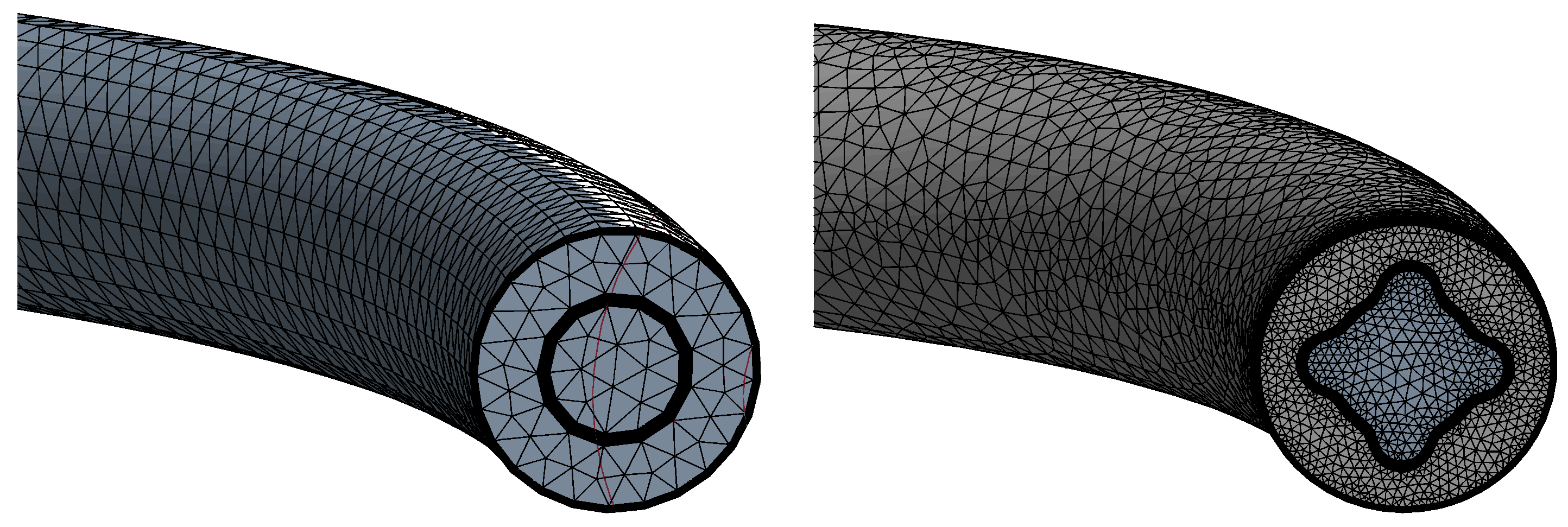
The mesh was generated for five heat exchanger geometries described above with element size of 1 mm. Figure 2 showed the mesh for geometry A and B, respectively. Several meshes were created with the aim of comparing the Nusselt number and selecting adequate mesh for simulations. The error between two mesh sizes was calculated according to Equation (1):
where and mean the Nusselt number for upper mesh and lower mesh, respectively.
According to the numerical results, the number of elements of each mesh was selected range from between elements for geometry A, up to and elements for geometry E, with the objective of showing independent results of the mesh and errors lower than 1%. An independence mesh analysis was carried out, each of the geometries was evaluated with different numbers of elements and calculating their Nusselt number, the numerical results are shown in Figure 3, and they agree with [14]. As can be seen in Figure 3 the number of elements is greater than elements for geometry B, elements for geometry C and elements for geometry D.
According to the numerical results, the number of elements of each mesh was selected between and with the objective of showing independent results of the mesh and errors lower than 1%. An independence mesh analysis was carried out, each of the geometries was evaluated with different numbers of elements and calculating their Nusselt number, the numerical results are shown in Figure 3, and they agree with [14]. As can be seen in Figure 3 the number of elements in the mesh does not affect the results, and they are independent when the number of elements is greater than for geometries from B to D, for geometry A is necessary to use a mesh with a smaller element size. Figure 4 shows the evolves of Nusselt number trough the heat exchangers showing that after the change in Nusselt number is minimum.
2.2. Numerical Computation
Five Dean numbers were simulated: 4410, 4880, 5340, 5810 and 6030 for an external tube keeping constant the design and increasing the Reynolds number. The inner tube had a constant Dean number of 1000 for all simulations. The inlet and outlet temperatures in the internal tube were fixed at 300 K and 380 K, respectively. The numerical computation was set up at convergence criterion less than and the total number of iterations were varied from 500 to 600. The Dean number for the external tube was calculated according Equation (2):
where is velocity average, is the density, is the dynamic viscosity and is the hydraulic diameter, it was computed as follows:
is the curvature diameter and it was calculated as follows:
then, A is the cross-sectional area and is the hydraulic diameter, is the helical diameter and is the outer diameter of internal tube.
The equations suggested by [7] for the physical-thermal properties of water such as density (), specific heat (), thermal conductivity () and dynamic viscosity () are computed and used in this investigation.
The differential equations governing the turbulent flow that describe the chaotic movement of the fluid inside heat exchanger can be written in the tensor form according to Equations (5)–(12). The Continuity balance expresses the net mass flow at the scale of the infinitesimal control volume as follows in Equation (5):
The momentum balance equation (see Equation (6)) states that the temporary increase of the linear momentum plus its net flow at the output must be equal to the sum of the forces acting on the infinitesimal control volume.
The first term of Equation (6) represents the change of momentum by convection, the second term is the pressure forces that act on the infinitesimal control volume, the third term indicates the tangential stress caused by the velocity gradients according to the first coefficient of effective viscosity and the last term () represents the centrifugal forces that act on the volume of infinitesimal control.
Energy balance equation states that the amount of energy change of the infinitesimal element is equal to the amount of heat added to the element plus the amount of work done on the element. The energy balance equation is shown in Equation (7).
The first term of Equation (7) expresses the net flow of energy, the second term is the pressure, the third term is the viscous forces and the fourth term represents the net heat flow that enters through the faces of the control volume due to temperature gradients. Where is the viscous heating term in energy equation, its represented by Equation (8).
For the turbulent model, k represents the kinetic energy associated with turbulence. The turbulent kinetic energy is shown in Equation (9):
where represents the turbulent Prandtl number.
In Equation (9), the first term represents the transport of k by convection, the second term expresses viscous diffusion and turbulent diffusion by pressure-velocity fluctuations, the third term represents the production of energy in large turbulent scales and the last term is the dissipation. The term is the parameter to calculate the generation of turbulent kinetic energy due to the mean velocity gradient and is represented by Equation (10).
While represents the dissipation of kinetic energy, it is represented by the turbulent dissipation energy as follows:
The model assumes that the turbulence viscosity is coupled to the governing equations via the relation in Equation (12).
where is the density and is a constant that must be determined empirically.
The empirical constants for the turbulence model are assigned the following values: , , , and . The values of these constants are the same as those of Launder and Spalding [15], the suggestion of [13] for was used.
The Nusselt number () and friction factor (f) for each simulation was calculated according:
where is the hydraulic diameter, is the thermal conductivity and the convective heat transfer coefficient is determined as:
where is mass flow of external fluid, and are the outlet and inlet temperature respectively of external fluid, is internal tube wall average temperature, is external fluid average temperature, and is internal tube wall area.
Darcy-Weisbach factor friction it was calculated as follows:
where is pressure drop and l is heat exchanger length.
3. Results and Discussion
The computer model has been carefully verified using the numerical results of [13]. Figure 5 shows the Nusselt number reported by [13] and our numerical results for tube-in-tube heat exchanger without passive technique improvements (Geometry A). The models present a similar trend. The discrepancies between the results can be assumed to the incorporation of deflectors in the model by [13]. As can be seen, the model agrees with the numerical (geometry A), numerical results by [13] and experimental data reported by [13]. An average increment of Nusselt number is calculated to compare the numerical results presented. The following equation was used:
where is the Nusselt number of geometry B, C, D, or E and is the Nusselt number of geometry A.
The geometry B includes the passive technique without turns into the internal tube, an approximately 28.8% in the Nusselt number was estimated in comparison with geometry A. Its average increment remains practically constant when rising the Dean number from 4500 to 6000. It is interesting to note that the increases of the Nusselt number from one to three turns of twist in the internal tube were minor to approximately 3%, nevertheless, the biggest increase was observed when the number of turns changes from three to five in approximately 5.7%. The velocity and temperature contours in the internal and annular flow were analyzed in this section considering a Dean number equal to 4411 in the external fluid. In Figure 6, the relationship between the number of Nusselt of each geometry proposed with twist and the geometry proposed by [13] is calculated. As can be seen, the heat transfer in the heat exchanger is increased with the number of twists in the tube, a slight increase is appreciated as the number of Dean is increased.
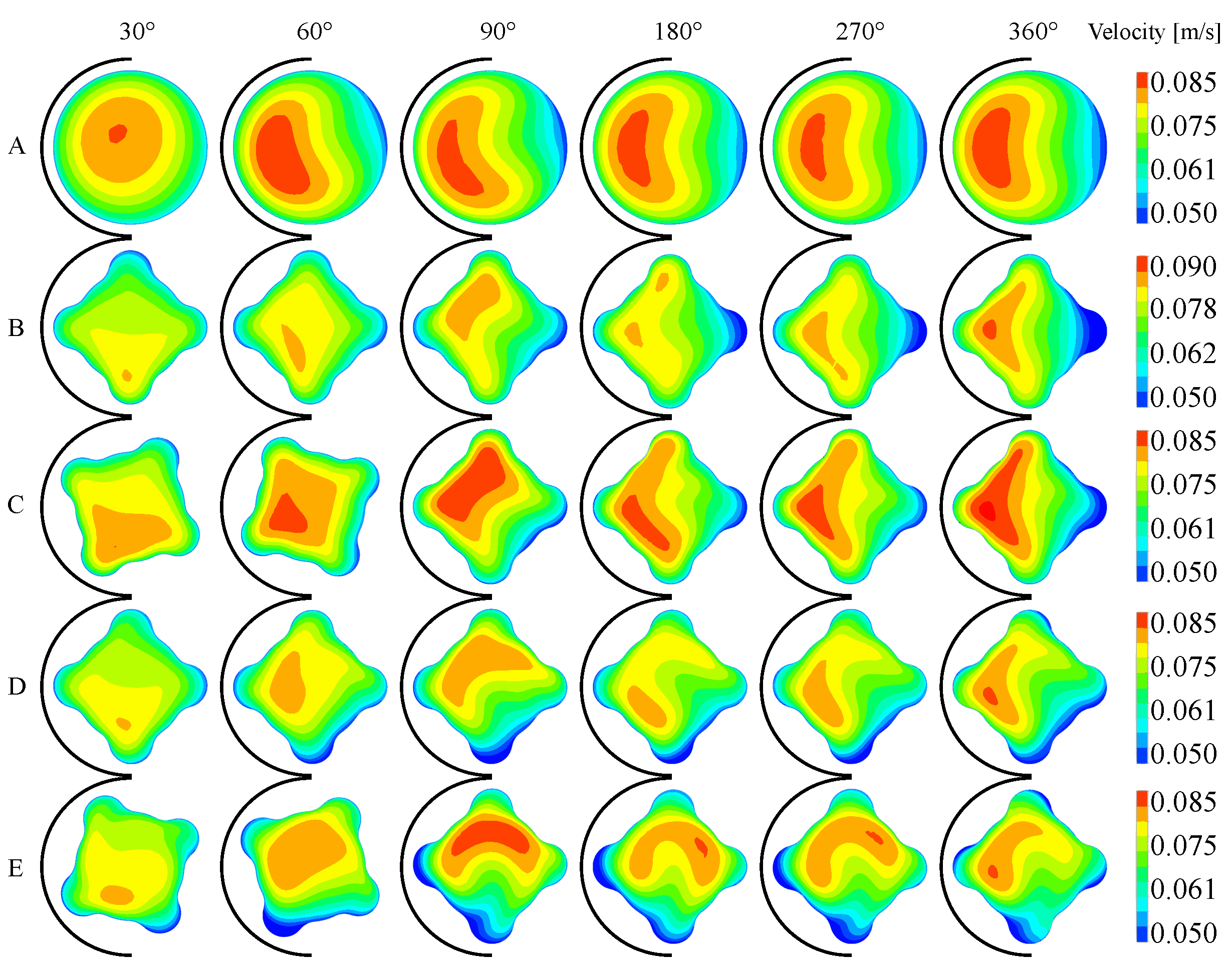
Figure 7 illustrates the velocity contours for the internal fluid of five geometries of the heat exchanger. The geometries were arranged in rows, the rows (A), (B), (C), (D) and (E) show the velocity contours considering: a smooth tube, a geometry modified with passive technique without twist, a geometry modified with passive technique with one, three, and five turns, respectively. The columns report different cross-section (30, 60, 90, 180, 270 and 360). Arcs located to the left of every field indicate the exterior of the heat exchanger.
As can be seen in the numerical results of model (A), the velocity contours practically remain the same. This behavior is similar to results reported by [13]. In four geometries (B) to (E), the velocity contour changed from the position of 90 appreciating different velocity profiles; however for angles from 180 to 360 small variations are observed in the velocity fields, this is evidence of total developed flow. For the models (A) to (D), the maximum velocity was observed towards the outside of heat exchangers, this effect is attributable to the centrifugal force and secondary flows caused by the curvature of the helical coil, the effect of these forces over the velocity is the same that reported by [3] . As can be seen, for the numerical results of models (D) and (E) it is not possible to observe a pattern in the velocity contour possibly attributed to the effect of twist along the tube.
Figure 8 shows the temperature contours for the five models described previously. In geometries (A) to (D) the maximum temperature was observed towards the exterior of the heat exchanger, this is due to the center of the vortex formed by the secondary flows. In addition, the movement of fluid in the form of vortex produces an increase in the heat transfer mechanism, possibly caused for the increase of velocity contours in these sections (see Figure 7). For the models (D) and (E), the temperature contours were very similar from 30 to 360, this behavior may be the reason the Nusselt number presents an insignificant increase when the twist increases from three to five (Figure 7). Figure 9 shows the velocity contour for annular flow. For models from (B) to (E), a pattern was not appreciated in velocity fields, small variations were observed in the velocity fields from 270 to 360, but this is not enough to affirm that there is a developed flow. The secondary flows observable in models from (B) to (E) were more turbulent than model (A), the passive technique benefits the turbulence and consequently the heat transfer. Figure 10 illustrates the temperature contour for annular flow. For models from (B) to (E), the temperature increases uniformly, there are no significant temperature differences between the models in the cross-section selected. The temperature contours correlate with the velocity contours, as previously showed in Figure 9.
As can be seen, Figure 5, Figure 6, Figure 7, Figure 8, Figure 9 and Figure 10 provides evidence of the increase of Nusselt number when the Reynolds number was increases. The increases of heat transfer from geometry A to E can be attributed to different reasons: the secondary flow originated by helical coil and twist, centrifugal force, increase in turbulence due to twist and the velocity distribution shown in Figure 7 and Figure 9.
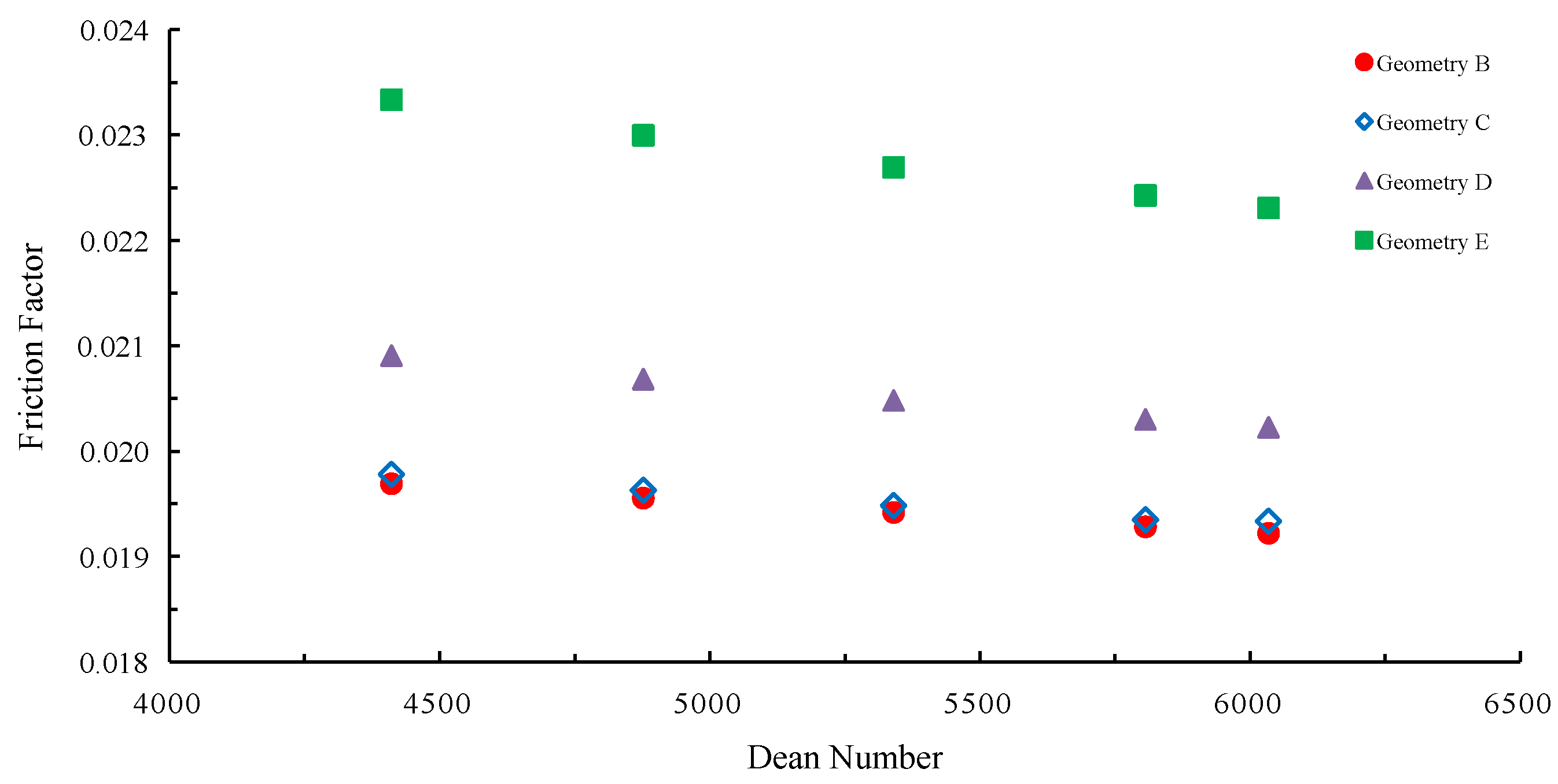
Figure 11 shows the average Darcy friction factor as a function of the Dean number, where a decrease in the friction factor is observed as the Dean number increases. When modifying geometry B to geometry C, the friction factor increased by 0.4%. The reduction of the friction factor indicates a reduction in the pressure drop because these are directly proportional. This reduction can be due to the increase of the cross-sectional area that in the modified geometries is greater than the circular smooth tube. As the twist of the tube increases (geometries D and E) the friction factor continues to increase by 6 and 17% for the geometry D and E respectively, showing that the increase in twist makes the flow of the fluid through the heat exchanger difficult.
4. Conclusions
The numerical model using CFD of a helical tube-in-tube heat exchanger with and without passive techniques was successfully carried out. The main contributions of the present research are the following:
- The numerical model of [13] was reproduced considering the assumptions and experimental information described in that research. This evidence gives confidence about the evaluation when the passive techniques were added.
- With reference to the first passive technique applied the addition of four ridges in the inner tube. Shows an increment up to 28.8% in the Nusselt number were calculated for all cases under study. Then, when the Dean number increased from 4500 to 6000 the Nusselt number increases linearly. This increment can be caused by the velocity contours generated by the addiction of ridges and its influence on heat transfer. In the annular section of heat exchanger, the ridges decrease the centrifugal forces generated by the action of a helical coil.
- When the twist of the internal tube was added from one to three turns, an increase up to 3% in the Nusselt number was calculated. The biggest increase, up to 9% was calculated when five turns were simulated.
- The numerical results of this research will be considered to design other passive techniques without twist in tube. The previous suggestion is supported by the increase in the heat transfer, this work assumes that there is no compromise in the mechanical integrity of the tubes caused by twist.
In this work the numerical results, analysis, and discussion were presented; if more information is needed for future research lines, the corresponding author can provide it upon request.
Author Contributions
The authors contribute equally to this manuscript. Investigation, D.C.; Methodology, M.V.; Software, J.G.A.; Writing—review and editing, B.A.E-T.
Funding
This research received no external funding.
Conflicts of Interest
The authors declare no conflict of interest.
References
- Li, P.; Liu, Z.; Liu, W.; Chen, G. Numerical study on heat transfer enhancement characteristics of tube inserted with centrally hollow narrow twisted tapes. Int. J. Heat Mass Transf. 2015, 88, 481–491. [Google Scholar] [CrossRef]
- Pan, C.; Zhou, Y.; Wang, J. CFD study of heat transfer for oscillating flow in helically coiled tube heat-exchanger. Comput. Chem. Eng. 2014, 69, 59–65. [Google Scholar] [CrossRef]
- Dean, W.R. XVI. Note on the motion of fluid in a curved pipe. Lond. Edinb. Dublin Philos. Mag. J. Sci. 1927, 4, 208–223. [Google Scholar] [CrossRef]
- Kurnia, J.C.; Sasmito, A.P.; Akhtar, S.; Shamim, T.; Mujumdar, A.S. Numerical Investigation of Heat Transfer Performance of Various Coiled Square Tubes for Heat Exchanger Application. Energy Procedia 2015, 75, 3168–3173. [Google Scholar] [CrossRef] [Green Version]
- García, A.; Solano, J.P.; Vicente, P.G.; Viedma, A. The influence of artificial roughness shape on heat transfer enhancement: Corrugated tubes, dimpled tubes and wire coils. Appl. Therm. Eng. 2012, 35, 196–201. [Google Scholar] [CrossRef]
- Rainieri, S.; Bozzoli, F.; Pagliarini, G. Experimental investigation on the convective heat transfer in straight and coiled corrugated tubes for highly viscous fluids: Preliminary results. Int. J. Heat Mass Transf. 2012, 55, 498–504. [Google Scholar] [CrossRef]
- Zachár, A. Analysis of coiled-tube heat exchangers to improve heat transfer rate with spirally corrugated wall. Int. J. Heat Mass Transf. 2010, 53, 3928–3939. [Google Scholar] [CrossRef]
- Salpingidou, C.; Misirlis, D.; Vlahostergios, Z.; Flourous, M.; Donnerhack, S.; Yakinthos, K. Numerical modeling of heat exchangers in gas turbine using CFD computations and thermodynamic cycle analysis tools. Chem. Eng. Trans. 2016, 52, 517–522. [Google Scholar]
- Bakosova, M.; Oravec, J.; Vasickaninova, A.; Meszaros, A. Neural-network-based and robust model-based predictive control of a tubular heat exchanger. Chem. Eng. Trans. 2017, 61, 301–306. [Google Scholar]
- Yang, X.; Xiong, T.; Dong, J.L.; Li, W.X.; Wang, Y. Investigation of the dynamic melting process in a thermal energy storage unit using a helical coil heat exchanger. Energies 2017, 10, 1129. [Google Scholar] [CrossRef]
- Sharifi, K.; Sabeti, M.; Rafiei, M.; Mohammadi, A.H.; Shirazi, L. Computational fluid dynamics (CFD) technique to study the effects of helical wire inserts on heat transfer and pressure drop in a double pipe heat exchanger. Appl. Therm. Eng. 2018, 128, 898–910. [Google Scholar] [CrossRef]
- Ju-Lee, H.; Ryu, J.; Hyuk-Lee, S. Influence of Perforated Fin on Flow Characteristics and Thermal Performance in Spiral Finned-Tube Heat Exchanger. Energies 2019, 12, 556. [Google Scholar] [CrossRef]
- Kumar, V.; Saini, S.; Sharma, M.; Nigam, K.D.P. Pressure drop and heat transfer study in tube-in-tube helical heat exchanger. Chem. Eng. Sci. 2006, 61, 4403–4416. [Google Scholar] [CrossRef]
- Valdés-Ortiz, M.; Ardila-Marin, J.G.; Martínez-Pérez, A.F.; Betancur Gómez, J.D. Via ANSYS Numerical Analysis of Heat Exchangers with Passive Improvement: Case Study Meshing Density and Turbulence Model. Rev. CINTEX 2017, 22, 59–68. [Google Scholar]
- Launder, B.E.; Spalding, D.B. The numerical computation of turbulent flows. Comput. Methods Appl. Mech. Eng. 1974, 3, 269–289. [Google Scholar] [CrossRef]
Figure 1.
Simulated control volumes: external and internal flows with the second passive technique evolution. A: tube-in-tube. B: four ridges without twist. C: four ridges with 1 twist. D: four ridges with 3 twist. E: four ridges with 5 twist.
Figure 1.
Simulated control volumes: external and internal flows with the second passive technique evolution. A: tube-in-tube. B: four ridges without twist. C: four ridges with 1 twist. D: four ridges with 3 twist. E: four ridges with 5 twist.
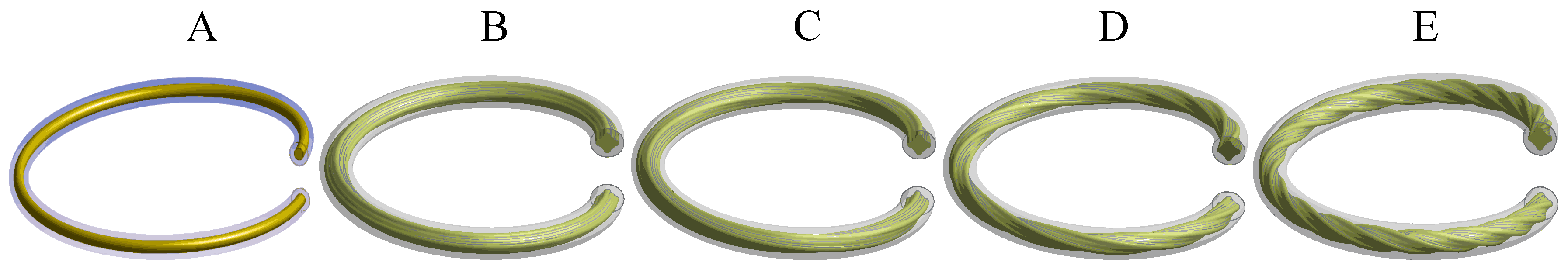
Figure 2.
Mesh for geometry A (tube-in-tube) and B (four ridges without twist).

Figure 3.
Mesh independence study.

Figure 4.
Nusselt number for several positions in the first turn of heat exchanger.

Figure 5.
Nusselt number vs. Dean number for outer tube.
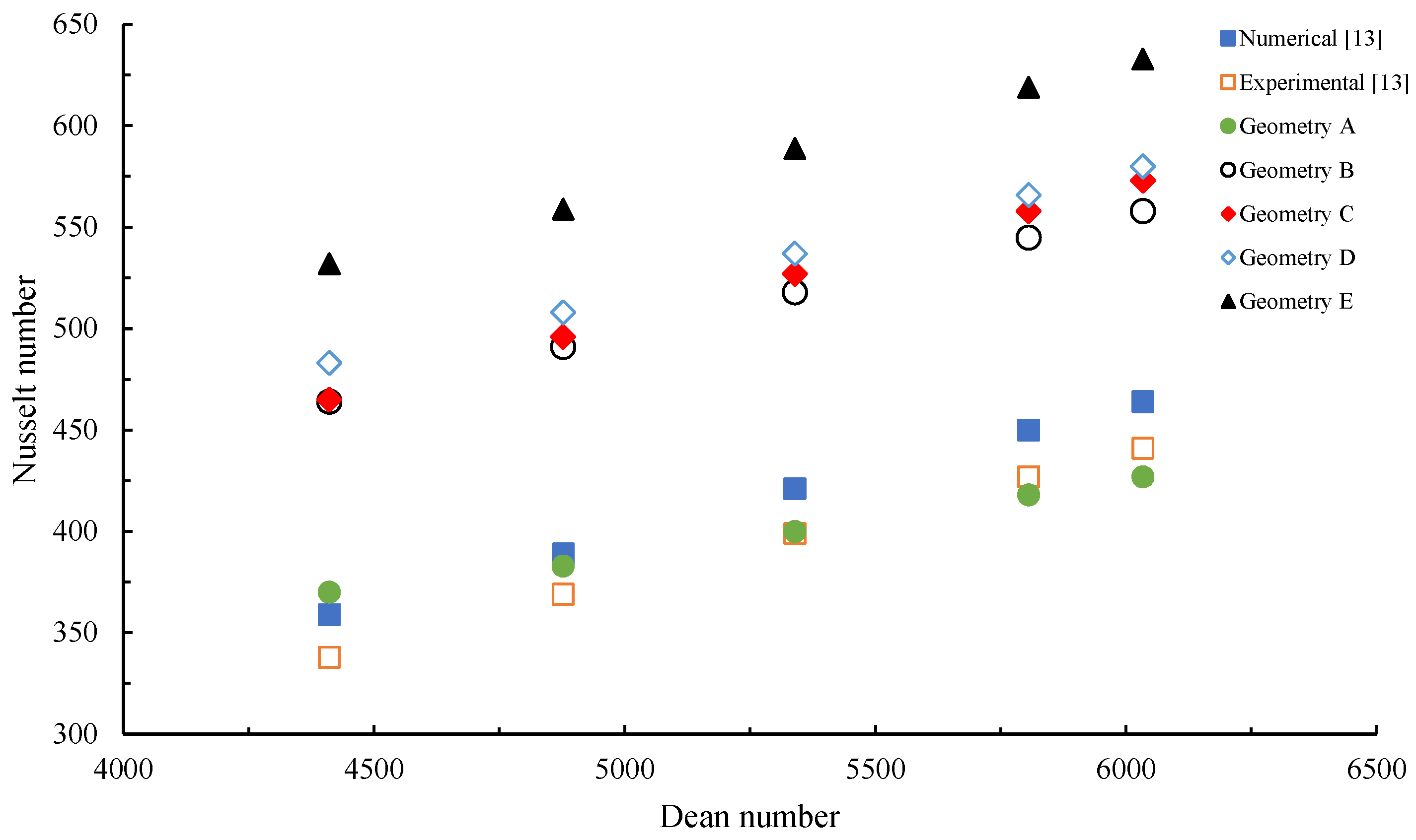
Figure 6.
Comparison of Nusselt number for each one of geometries.

Figure 7.
Velocity contours for the inner tube of five heat exchangers with Dean number 1000 for the inner tube and with Dean number 4411 for the outer tube. A: tube-in-tube. B: four ridges without twist. C: four ridges with 1 twist. D: four ridges with 3 twist. E: four ridges with 5 twist.
Figure 7.
Velocity contours for the inner tube of five heat exchangers with Dean number 1000 for the inner tube and with Dean number 4411 for the outer tube. A: tube-in-tube. B: four ridges without twist. C: four ridges with 1 twist. D: four ridges with 3 twist. E: four ridges with 5 twist.

Figure 8.
Temperature contours for the inner tube with Dean number 1000 for inner tube and with Dean number 4411 for outer tube. A: tube-in-tube. B: four ridges without twist. C: four ridges with 1 twist. D: four ridges with 3 twist. E: four ridges with 5 twist.
Figure 8.
Temperature contours for the inner tube with Dean number 1000 for inner tube and with Dean number 4411 for outer tube. A: tube-in-tube. B: four ridges without twist. C: four ridges with 1 twist. D: four ridges with 3 twist. E: four ridges with 5 twist.
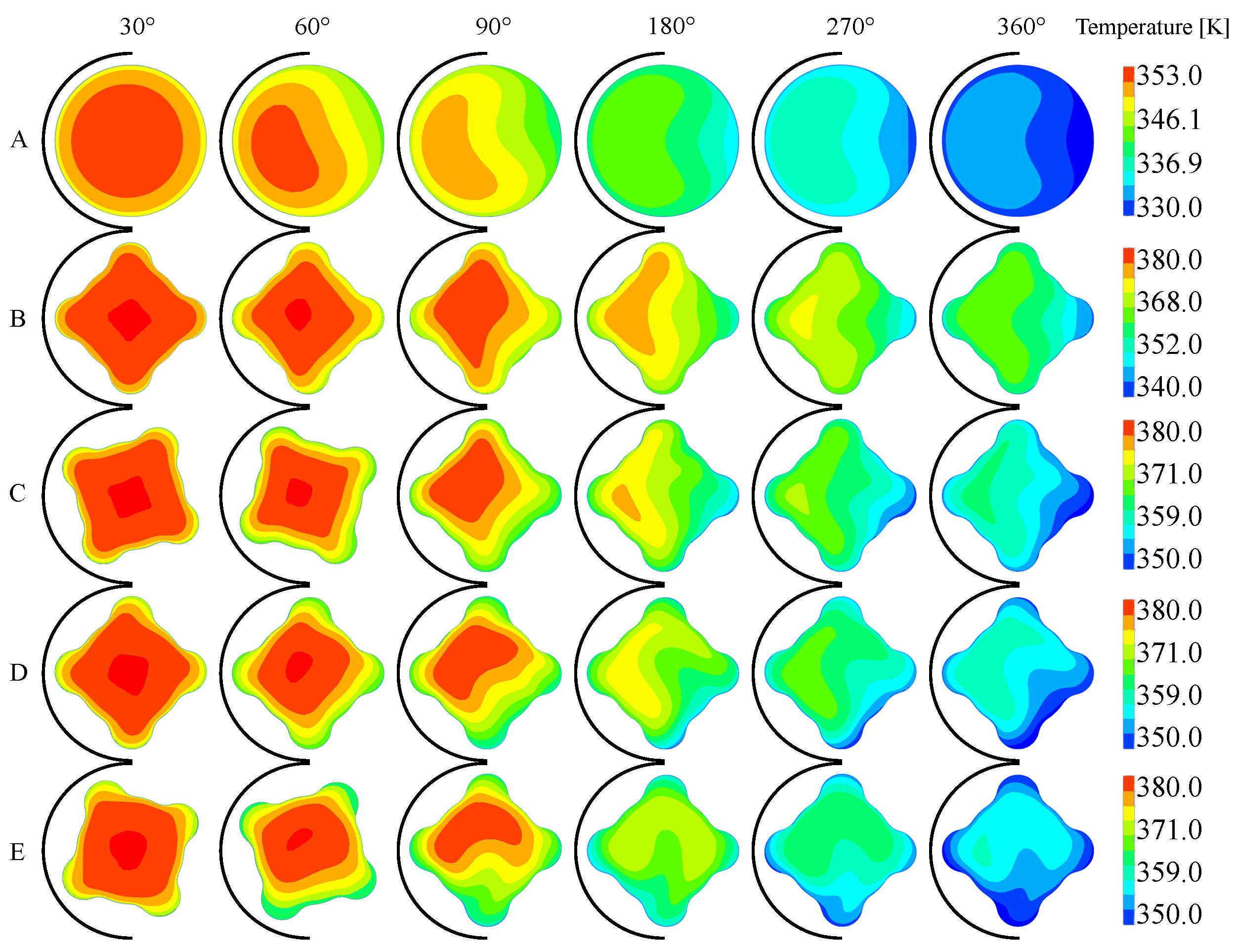
Figure 9.
Velocity contours for the outer tube with Dean number 1000 for inner tube and with Dean number 4411 for outer tube. A: tube-in-tube. B: four ridges without twist. C: four ridges with 1 twist. D: four ridges with 3 twist. E: four ridges with 5 twist.
Figure 9.
Velocity contours for the outer tube with Dean number 1000 for inner tube and with Dean number 4411 for outer tube. A: tube-in-tube. B: four ridges without twist. C: four ridges with 1 twist. D: four ridges with 3 twist. E: four ridges with 5 twist.
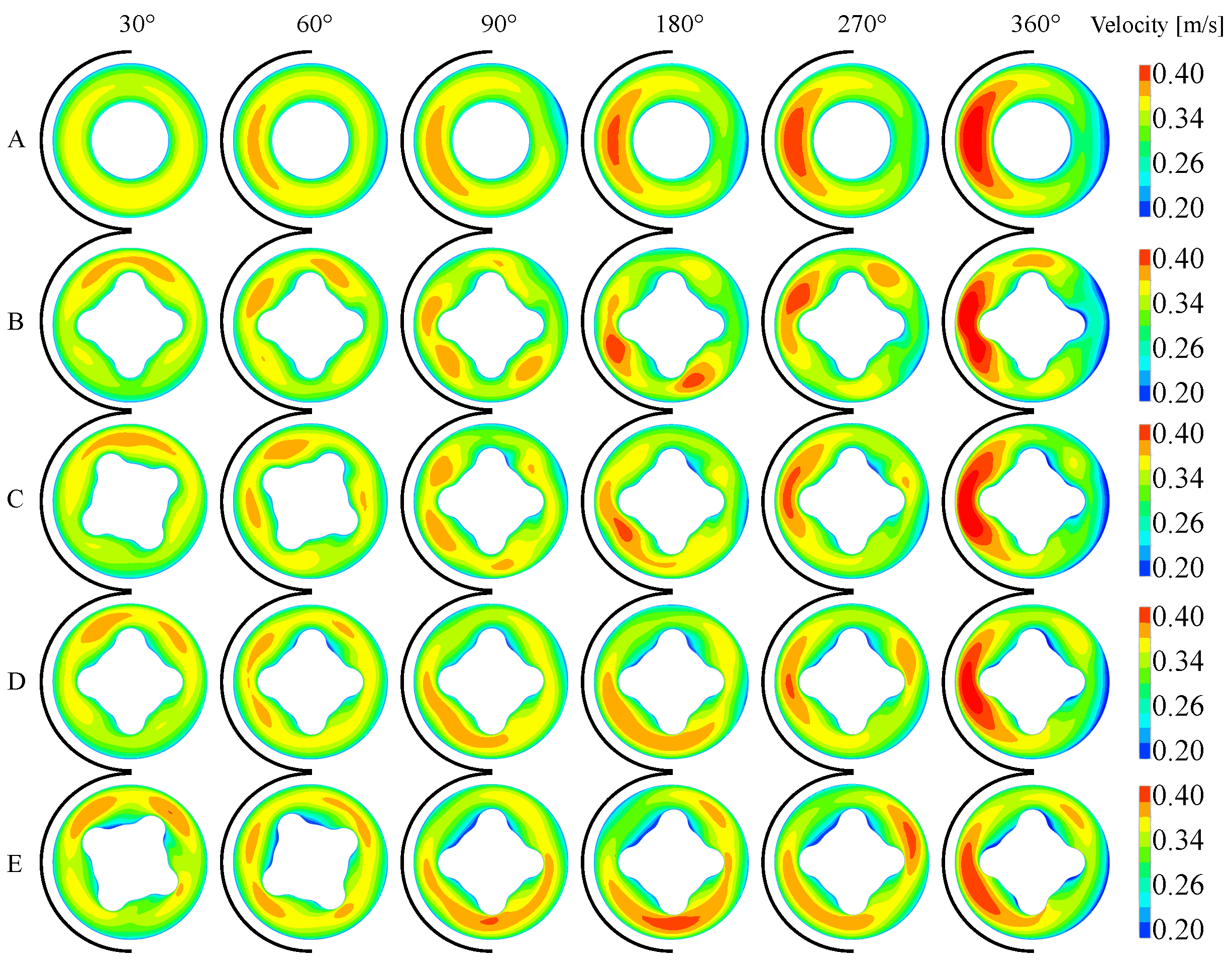
Figure 10.
Temperature contours for the outer tube with Dean number 1000 for inner tube and with Dean number 4411 for outer tube. A: tube-in-tube. B: four ridges without twist. C: four ridges with 1 twist. D: four ridges with 3 twist. E: four ridges with 5 twist.
Figure 10.
Temperature contours for the outer tube with Dean number 1000 for inner tube and with Dean number 4411 for outer tube. A: tube-in-tube. B: four ridges without twist. C: four ridges with 1 twist. D: four ridges with 3 twist. E: four ridges with 5 twist.
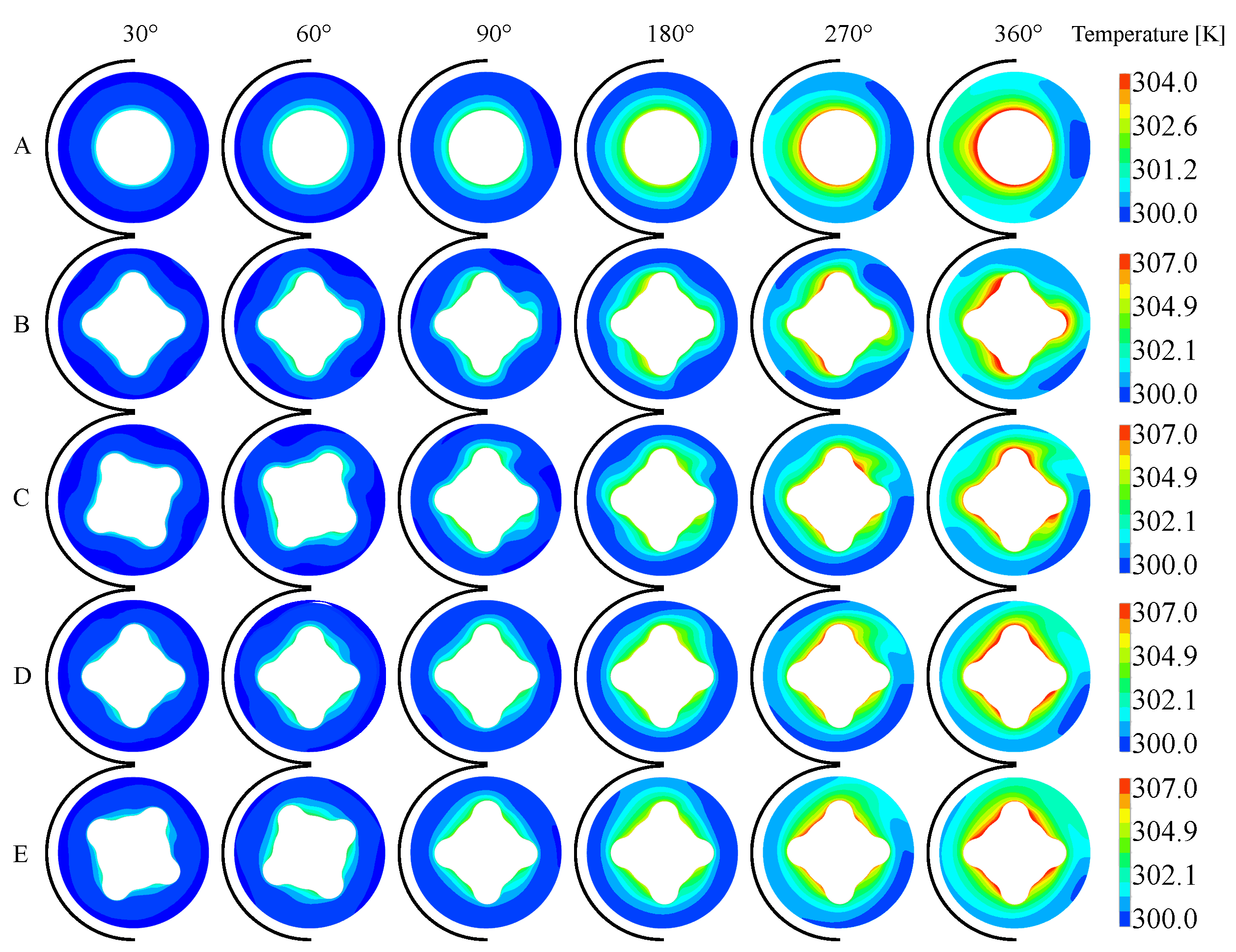
Figure 11.
Friction factor vs. Dean number for each one of geometries.

Table 1.
Geometry and boundary conditions.
| Geometry and Boundary Conditions | Internal Tube | External Tube |
|---|---|---|
| Outer diameter (m) | 0.0254 | 0.0508 |
| Helical diameter (m) | 0.762 | 0.762 |
| Pitch (m) | 0.1 | 0.1 |
| Velocity (m/s) | 0.073 | 0.32–0.44 |
| Dean number (dimensionless) | 1000 | 4410–6030 |
| Prandtl number (dimensionless) | 7 | 7 |
Table 2.
Geometry of the five models presented in this work.
| Geometry | Passive Modification |
|---|---|
| A | tube-in-tube |
| B | four ridges without twist |
| C | four ridges with 1 twist |
| D | four ridges with 3 twist |
| E | four ridges with 5 twist |
© 2019 by the authors. Licensee MDPI, Basel, Switzerland. This article is an open access article distributed under the terms and conditions of the Creative Commons Attribution (CC BY) license (http://creativecommons.org/licenses/by/4.0/).
Share and Cite
MDPI and ACS Style
Valdes, M.; Ardila, J.G.; Colorado, D.; Escobedo-Trujillo, B.A. Computational Model to Evaluate the Effect of Passive Techniques in Tube-In-Tube Helical Heat Exchanger. Energies 2019, 12, 1912. https://doi.org/10.3390/en12101912
AMA Style
Valdes M, Ardila JG, Colorado D, Escobedo-Trujillo BA. Computational Model to Evaluate the Effect of Passive Techniques in Tube-In-Tube Helical Heat Exchanger. Energies. 2019; 12(10):1912. https://doi.org/10.3390/en12101912
Chicago/Turabian StyleValdes, Miyer, Juan G. Ardila, Dario Colorado, and Beatris A. Escobedo-Trujillo. 2019. "Computational Model to Evaluate the Effect of Passive Techniques in Tube-In-Tube Helical Heat Exchanger" Energies 12, no. 10: 1912. https://doi.org/10.3390/en12101912
Note that from the first issue of 2016, this journal uses article numbers instead of page numbers. See further details here.