Mathematical Modeling and Simulation of Nanoparticle-Assisted Enhanced Oil Recovery—A Review

1
Centre of Advanced Electromagnetics, Universiti Teknologi Petronas, Bandar Seri Iskandar 32610, Malaysia
2
Department of Fundamental and Applied Sciences, Universiti Teknologi Petronas, Bandar Seri Iskandar 32610, Malaysia
*
Author to whom correspondence should be addressed.
Energies 2019, 12(8), 1575; https://doi.org/10.3390/en12081575
Submission received: 10 December 2018
/
Revised: 5 March 2019
/
Accepted: 5 March 2019
/
Published: 25 April 2019
(This article belongs to the Special Issue Latest Research Progress for Nanotech for Oil and Gas)
Abstract
:In the last two decades, nanotechnology has flourished due to its vast number of applications in many fields such as drug delivery, oil and gas, and thermal applications, like cooling and air-conditioning. This study focuses on the applications of nanoparticles/nanofluids in the Enhanced Oil Recovery (EOR) process to increase oil recovery efficiency. To understand the nanoparticle-assisted EOR process, the first step is to understand the flow characteristics of nanoparticles in porous media, including entrapment and release in the pores and the behavior of nanoparticles under high temperatures, pressures, and salinity levels and in the presence of external electric and magnetic fields. Also, the process looks at the roles of various pore distributions during their application as EOR agents. The experimental approaches are not only time consuming, but they are also cumbersome and expensive. Hence, the mathematical models could help to facilitate the understanding of the transport and interaction of nanofluids in a reservoir and how such processes can be optimized to get maximum oil recovery and, in turn, reduce the production cost. This paper reviews and critically analyzes the latest developments in mathematical modeling and simulation techniques that have been reported for nanofluid-assisted EOR. One section is dedicated to discussing the challenges ahead, as well as the research gaps in the modeling approach to help the readers to also contribute to further enlightening the modeling nanofluid-assisted EOR process.
1. Introduction
The primary energy resource in the current decade is still hydrocarbons. Renewable sources of energy are in the development phase; hence, they cannot fulfill energy requirements and need a lot of research and development in terms of efficiency and cost to make them viable replacements to the hydrocarbons [1].
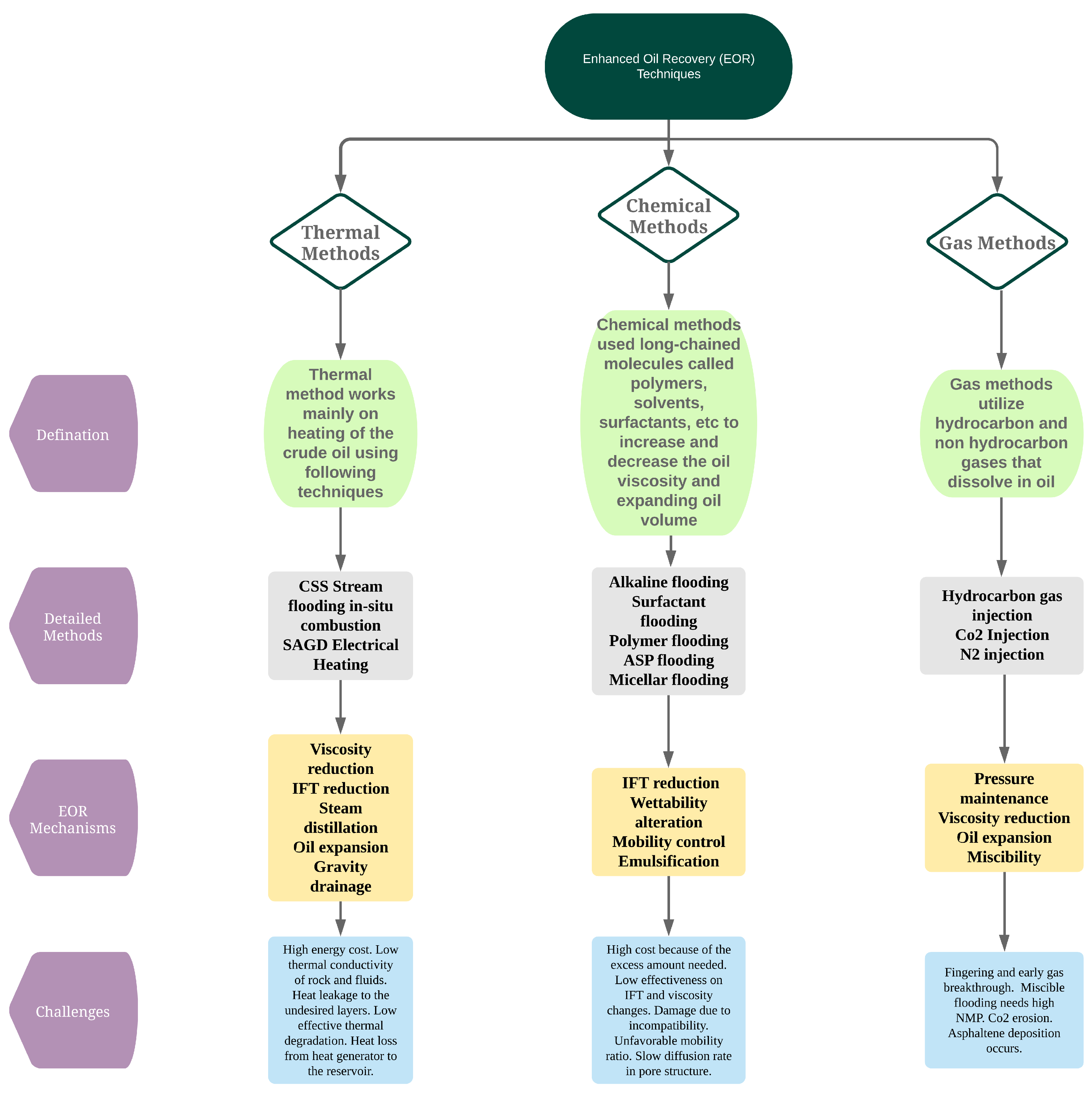
The production of hydrocarbon energy has to be increased to fulfill the rising demand for energy and also to reduce the production costs. To achieve this goal, maximum extraction should be completed from the existing operational reservoirs, since a vast amount (up to 60%) of the oil remains untouched in the reservoirs due to limitations in the oil recovery process [2]. The process of oil extraction from the reservoirs has been classified into three different categories: (1) primary oil recovery, (2) secondary oil recovery, and (3) enhanced oil recovery [3]. Enhanced Oil Recovery (EOR) comes into the picture after secondary recovery has taken place, in which up to 35–40% of the Original Oil In Place (OOIP) in the reservoir has been extracted using water flooding techniques. To extract the remaining 60–65% of oil, different EOR techniques have been discovered and employed in the reservoirs, and these have been categorized mainly into the following three groups, as discussed in [4,5]: (1) thermal methods, (2) gas methods, and (3) chemical methods. When the EOR methods are applied in the reservoir, they change the characteristics of the reservoir and the oil, for example, the wettability, interfacial tension, and mobility of oil, which helps with the movement of the oil to the extraction point; hence, oil can be pumped out. The details of the methods based on the above classifications are given in Figure 1. It also explains the EOR mechanism as well as its limitations and challenges.
From Figure 1, it can be inferred that EOR technology usually poses some challenges. The main challenge for the implementation of successful EOR techniques in the field is attaining a high recovery at a low production cost. The other limitation of the EOR techniques is that they are not environmentally friendly. For example, in the case of gas methods, if hazardous gases are inserted into the reservoir, the gases penetrate through the outlet and mix with the environment. Hence, we need an enhanced oil recovery method which has better recovery capacity, is cost-effective, and is also environmentally friendly [4].
Over the past years, nanoparticle research has attracted the interest of researchers because of its vast applications in engineering and medical fields. Numerous studies have also been carried out regarding the use of nanoparticles in the oil and gas sector, especially for hydrocarbon recovery. The use of nanoparticles (NPs) addresses some of the critical challenges faced in EOR methods. For example, in chemical methods, the chemicals get adsorbed in the porous medium which reduces the permeability of the reservoir. Hence, because of the very small size of nanoparticles (the size of NPs ranges from 1 to 100 nm in radius) this challenge can be solved easily [6]. When nanoparticles are injected into the reservoir, they change the wettability of the core and also reduce the interfacial tension between oil and the rocks [2]. Different properties of nanoparticles have been considered to study their effects on oil recovery such as particle size, ionic composition, behavior with magnetic and electric fields, as well as heat transfer capability. The most frequently used and researched nanoparticles are , , and . These nanoparticles are in high demand due to their important qualities as EOR agents when compared with the currently injected materials used in the reservoir for EOR applications. The size of nanoparticles is 1–100 nm, which is smaller than the pore and throat sizes [7]. As experimental studies have given in-depth analyses of NP-assisted EOR techniques, different article reviews that have been published have discussed the progress in experimental and theoretical studies in terms of newly developed nanomaterials and their limitations, as well as the challenges ahead [2,4,5,7,8,9,10,11,12].
Figure 2 shows the recent research papers in nanotechnology applications. The figure gives a clear understanding of the popularity of nanotechnology/nanomaterials in oil and gas applications, concentrated on EOR techniques. It also shows that there are fewer research papers involving theoretical study or modeling as compared to experimental research. A fundamental and theoretical understanding of nanoparticle-assisted EOR is important to make an efficient EOR design. The mathematical modeling and simulations also help to facilitate the understanding of the behavior of more nanomaterials in cost-effective ways as compared to a complete experimental approach. This review gives an overview of existing mathematical models and simulations for nanoparticle-assisted EOR, along with their advantages and limitations. Firstly, we discuss the basic flow of nanoparticles in the different porous media. Then, the following sections are dedicated to the mathematical modeling of nanoparticle-assisted EOR for different reservoirs and in the presence of different physical conditions. The last section is dedicated to discussing future challenges in the modeling and simulation work of nanoparticle-assisted EOR.
2. Nanoparticle Flow in Porous Media
2.1. Filtration Theory
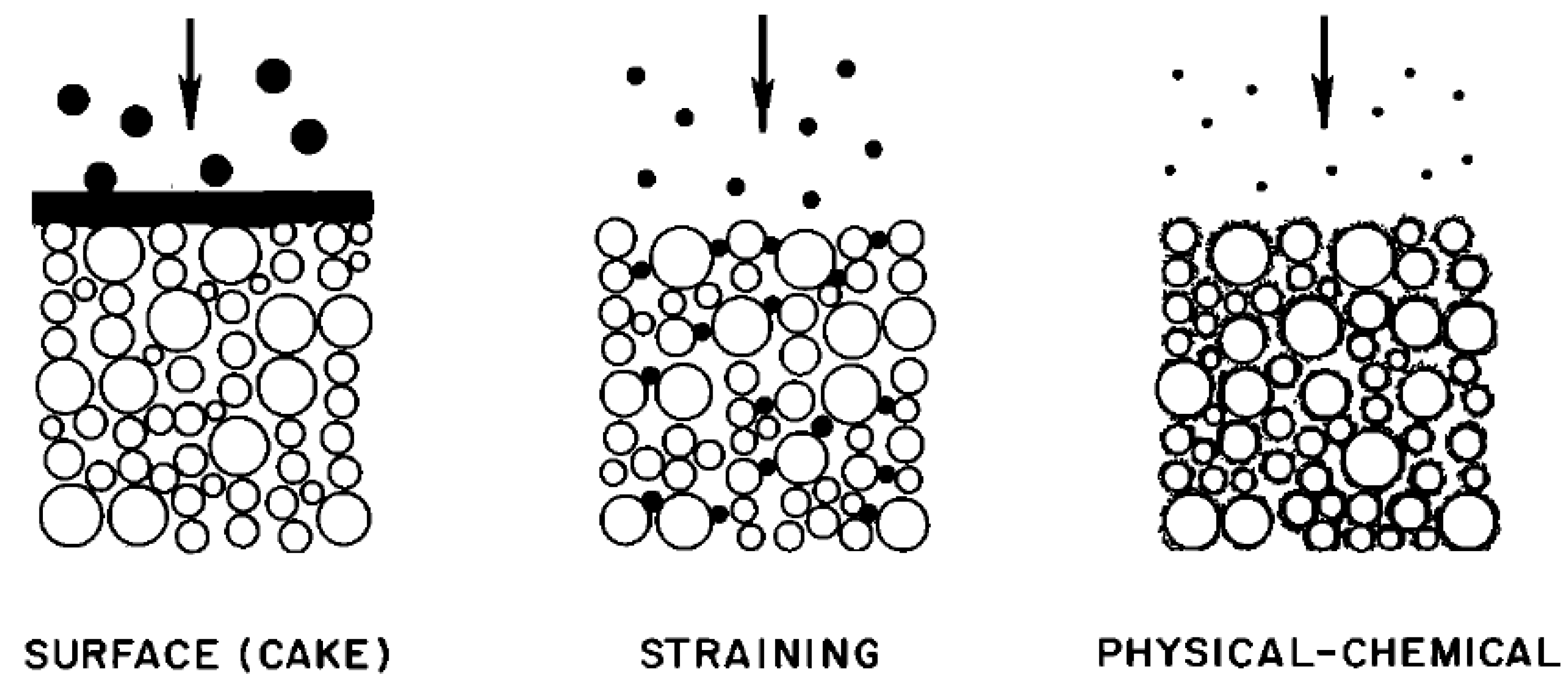
In order to study the flow of nanoparticles in porous media, it is essential to understand the principles of filtration theory. Filtration theory is the gateway towards gaining a superior comprehension of nanoparticle flow in porous media. This theory categorizes the particles in three different size regimes based on the size of the porous media [13] as shown in Figure 3. The first regime includes particles with a size comparable to or higher than the grains of porous media. Here, the permeability is significantly reduced because of the formation of a filter cake at the medium’s surface. Another regime involves particles of sizes somewhat smaller than those of the grains. Hence, the permeability reduction is less severe than the previously described regimes. In the third kind of regime, the particle sizes are smaller than the grain size. As expected, the permeability reduction is much less. In fact, it is the physiochemical processes, not the size, that are the influencing factors in this permeability regime. Examples of the processes include the surface roughness of soil grain gatherers, the interfacial elements of a double layer of particles, particle and particle–collector authority collaborations, the surface charge heterogeneity of nanoparticles and soil grain collectors, and numerous others. Other properties that influence the transport of nanoparticles include their size, shape, and agglomeration state [14]. In the current literature, the authors are interested in reviewing the transport of nanoparticles in porous media. The permeability reduction is expected to be influenced by the interaction between nanoparticles and the interaction between nanoparticle and the surface of porous media. In this regime, they are not expected to block any pore throat.
2.2. Transport Model Approach
Researchers have used two methods to contemplate the flow of nanoparticles in the porous media. In the first method, the Lagrange method, the nanoparticles are traced and coupled with the flow equation using interaction terms [15,16,17,18]. In the second method, the Eulerian method, the model equations are derived using the mass balance concept, and nanoparticles are not tracked. An advection–dispersion equation is considered, and a filtration term is added to the equation to predict the flow of the nanoparticles in the porous media.
3. Mathematical Modeling of Nanoparticle Transport in Porous Media
As nanoparticles gain popularity among researchers due to their vast number of applications, several researchers have started to carry our theoretical studies of nanoparticles in porous media by building different mathematical models. Goldberg et al. [19] presented a review of all the models used in nanoparticle transport in saturated porous media and calculated the efficiency of the models to predict the flow. The models were divided into different categories based on the phenomenon responsible for nanoparticle transport, which includes the flow equation along with a deposition term, remobilization, and blocking [15]. Goldberg et al. [19] suggested that the complexity of the models is not necessarily related to the prediction capabilities of nanoparticles.
To develop a mathematical model to predict the changes in reservoir characteristics after the injection of nanofluids in the reservoir, several researchers have developed different approaches, and these are discussed in the following sections. The transport of nanofluid in two-phase flow (oil and water) leads to changes in the wettability and permeability of the reservoir. To study these changes, Ju and Fan [20] developed a mathematical model for the transport of nanoparticles in porous media by considering the following assumptions: (1) the flow is one-dimensional under isothermal conditions, and the rock and fluids are supposed to be incompressible; (2) the porous medium is heterogeneous; (3) the oil and water flow in porous media follow Darcy’s law and the gravity force is neglected; (4) the nanoparticles are discretized into n-sized intervals; and (5) the viscosity and density of the fluids are constant, and oil and water are Newtonian fluids. Firstly, the model considers the flow of fluids in the porous media using Darcy’s law using the following Equation (1):
where x is the distance of particle in the reservoir, in the reservoir, t is time, is the porosity of the reservoir medium, is the effective permeability, and , and are the saturation, viscosity, and porosity of phase l (oil or gas), respectively.
The nanoparticles will either be in the oil phase or the water phase based on their properties. If hydrophobic nanoparticles are present, they will be in the oil phase, and if hydrophilic nanoparticles are present, then they will be in the water phase. The transport of nanofluids in the porous media is given by considering Brownian diffusion, as shown in Equation (2), because of the wettability properties of nanofluids:
where is the concentration of nanoparticles, is the dispersion coefficient of nanoparticles in size interval i in phase l, and is the net rate nanoparticle loss in interval i in phase l.
As nanoparticles are moving in the reservoir, they get entrapped and absorbed in the pores. Hence, it is important to consider the net loss rate of nanoparticles, which is given by [21] after the modification, as shown in Equation (3):
where is is the volume of nanoparticles in contact with phase l available on the pore surfaces per unit bulk volume of sandstone. Gruesbeck and Collins [22] gave an expression to evaluate the deposition of nanoparticles depending on the injected velocity which helps to give a better prediction of the loss of nanoparticles. Ju and Fan [20] reformed the model to better predict surface deposition, which is given by Equation (4):
The initial conditions to solve Equation (4) are given below:
The entrapment of nanoparticles in the interval i at time t is given below:
The initial conditions to solve above Equation (6) are given below:
The model predicts the recovery of oil after the injection of nanofluids, and it also helps to predict the permeability and porosity of the reservoir. Nanoparticle deposition in the pores leads to changes in the permeability and porosity of the reservoir. Ju and Dai [21] derived the equations for the calculation of the changes in the porosity and permeability of the reservoir after nanoparticle injection, which are shown as Equations (8) and (9), respectively:
The permeability can be calculated as shown in Equation (9):
The model is solved using the Implicit Pressure Explicit Saturation (IMPES) method. This model has successfully predicted the calculation of nanoparticle transport in porous media. This model is one of the initial models used to determine nanoparticle transport in porous media and has been cited by many researchers in later developments. The model was used in the carbonate system by Sepehri et al. [23] and was validated with experimental results. The model predicted an 8–10% increase in the recovery factor due to changes in wettability in comparison with the standard water flooding EOR method.
The calculation of the nanoparticle loss term is vital for the prediction of the flow of nanoparticles in the porous media. Many researchers have studied and calculated the nanoparticle loss term based on mechanistic and empirical modeling methods which are highlighted below. Cullen et al. [24] recommended calculating the extent of nanoparticle entrapment, which can be explained by the following equation:
where is the maximum retention capacity. To consider the detachment of nanoparticles, Bradford et al. [25] gave the Equation (11)
where is the coefficient of the first-order colloid attachment and is the coefficient of first-order colloid detachment. Table 1 presents the calculation of the loss term by different researchers and fitting parameters used in the deposition model.
The material balance approach was used to study the one-dimensional and single-phase flow of nanoparticles in porous media by [33,34,35]. The model equation is given by Equation (12). The fluid flow is considered to follow Darcy’s law and nanoparticle flow is considered to follow the Brownian diffusion:
The authors used the two-site model proposed by Zhang et al. [26,36], which is given in the above table to calculate the loss term R. The fitting of parameters in the Independent Two Site Model (ITSM) was done by an experimental study performed by the authors and a case study from the literature. The model was used to calculate the concentration of nanoparticles at different times and distances from the core. This concentration of nanoparticles was used for the calculation of power absorbed by nanoparticles injected into the core. This study can help to give an idea about the use of electromagnetic heating, along with nanoparticle concentration in the reservoir. The limitation of the model is that it does not consider the saturation of fluids. A drag reduction model was developed for hydrophobic nanoparticles by [37], and the model predicted the change in the wettability of the core surface and the change in the displacement of the well by numerical simulation using the IMPES method. For the nanoparticle flow in heterogeneous porous media [38], developed a mathematical modeling simulation using the alternating direction implicit scheme. The model can be used to optimize nanoparticle physical parameters for EOR applications.
3.1. Models of Nanoparticle Flow in Porous Media Considering the Multiphase Flow
3.1.1. Multiphase Fluid Flow
After the Ju and Fan [20] model, many researchers, especially the El-Amin et al. [39] group came up with many modifications for the multiphase flow of nanoparticles in the porous media. The model’s equations are given below from Equation (14) to Equation (20). The following governing equations give a two-phase flow in the porous media. The authors considered a two-phase immiscible incompressible flow inside a homogeneous permeable medium domain, which was administered by Darcy’s law, and the conditions for mass conservation for each phase are given as [40].
The saturation of the phases are constrained by
where w and o represent the wetting phase (water) and non-wetting phase (oil), respectively, P is the pressure in the porous media, v is the velocity vector of Darcy, S is the saturation, and is given as the relative permeability, and the general governing equation for the saturation is given in Equation (19), where is the viscosity. When the velocities of the wetting phase and non-wetting phase are added, they will be equal to zero. After simplifying the equation, the flow equation is given by
3.1.2. Nanoparticle Transport
The flow of nanoparticles can be divided into two categories based on the behavior of nanoparticles in water. If nanoparticles are hydrophobic, they remain in the oil, and if nanoparticles are hydrophilic, they remain in the water. Hence, only one phase equation can be considered for this. Nanoparticle movement is due to Brownian diffusion, as given in Equation (20):
where is the net rate loss of nanoparticles calculated using the Ju and Fan [20] model for the net loss of nanoparticles in the porous media. The model investigates the effect of variations in the water saturation, nanoparticle concentration, porosity, and permeability on the flow of nanoparticles in the porous media. The model is further modified to use sequestration [41]. In order to solve these nonlinear governing equations, the authors employed the cell centered finite difference method, along with the Implicit Pressure Explicit Saturation (IMPES) method. To improve the computational efficiency of the solution techniques, the authors solved the equations using the modified iterative IMPES method [42,43]. The authors also solved the complex nonlinear governing equations the arise in the multiphase flow problem using the stable and more accurate Galerkin’s method. The method was employed for spatial discretization along with a time integration method to give the the governing equation [44]. Then, the authors used the dimensional analysis method to study the impact of each parameter used in the governing equation of the model. After the dimensional analysis has been performed, different dimensional numbers can be introduced into the system, like the Darcy number, the Capillary number, and the Bond number [39]. Numerical simulations were performed to see the effect of dimensionless numbers on the physical variables.
3.2. Mathematical Modeling of Nanoparticle Transport in Anisotropic Porous Medium
The advection–dispersion equation for nanoparticle flow in saturated porous media may be written as shown in Equation (21). Salama et al. [15,38] explained the filtration model for saturated porous media with all the details shown below and developed a mathematical model for nanoparticle transport in anisotropic porous medium:
where c is the concentration of nanoparticles, is the Darcy velocity, is the porosity, is the dispersion tensor, R represents the entrapment and detachment of nanoparticles due to chemical reactions, and represents the source or sink term of the nanoparticle flow [15]. By considering the filtration theory, the deposition of nanoparticles is accompanied by fine migration, and it is coupled with the governing balance equation by combining the rate at which the mass is deposited with the mass accumulation term [15,45,46]; hence, we get the following equation:
where is the bulk density of solids and s is the concentration at the surface. This deposition rate is modeled as
where is the particle deposition coefficient which can be obtained using the flow velocity. With this method, particle deposition is an irreversible phenomenon, and s can grow continuously. Many researchers have used this process. To calculate the retardation of nanoparticles, He et al. [47] proposed a model which is shown below:
where is the distribution coefficient. The models mentioned above help to form the basic understanding for developing new models on nanoparticle transport in anisotropic porous media while accounting for site blocking. The nanoparticles are accounted for in the middle of an anisotropic domain by means of a source term. The anisotropy condition, which is known to influence the velocity and pressure fields, can be implemented with varied angles and ratios. The nanoparticle deposition in the pore space deteriorates the permeability, affecting both pressure and velocity. At large anisotropy values, both the peak concentration and minimum porosity drop. This suggests an increase in velocity, which can be associated with increased dispersion and deposition of nanomaterials.
3.3. Fractured Porous Media
In order to model nanoparticle flow in fractured porous media, many researchers have used the Discrete Fracture Model (DFM) [48,49]. The saturation equation used in the model is given below, along with the nanoparticle transport equation:
In the fractured porous media, the saturation equation should be modified for coupling between the saturation and pressure. The Equation (26) is given below:
where is the mass transfer between the matrix and fracture intersection. Similarly, the nanoparticle transport equations for flow in the matrix and fractured porous domain are given below:
The above mathematical model can be solved using spatial discretization. Specifically, the authors used the cell centered finite difference method to solve the model numerically. The multi-scale time splitting scheme was developed and used for the pressure equation, and numerical cases are presented below to verify the employment of the proposed numerical method in DFM models in the future. This model can be used for in depth study of recovery using nanoparticle-assisted EOR and can be employed to enhance and optimize the performance of the EOR system. The two phase simulation of magnetic nanoparticles in hydraulic fracture porous medium was done by Aderonke et al. [50]. The simulation results showed that the nanoparticles were mostly concentrated at the planes of sand-filled hydraulic fractures. The high concentration of nanoparticles in the hydraulic fractures compared to the surrounding porous medium can be used for more accurate location and tracking of the sand in the subsurface. This study highlighted one more application of nanoparticle-assisted EOR for fracture detection in hydraulic fracture porous medium.
3.4. Modeling of Nanoparticle Transport in Porous Media in the Presence of a Magnetic Field
Nano ferrofluids are one of the potential applications of nanotechnology because they use the external magnetic field to administer their flow inside the porous media. This could lead to increased oil recovery during pressure maintenance as it paves the way for several applications such as directing flow in reservoir monitoring and diverting flow in acid jobs to control and boost the injection fluid advancement. With the intention to mobilize ferrofluids through porous media, a strong external magnetic field with large magnetic susceptibility fluid is utilized. Nanoparticles with electromagnetic properties (such as iron oxide, , and zinc oxide) under waves generated from an electromagnetic source can be used to increase oil recovery. Although both direct and alternating magnetic fields are under investigation, researchers have considered the direct magnetic field. Magnetic particle suspension is usually due to the magnetization of the particles and their attraction towards the magnet. The orientation of the magnet does not have any impact on the movement of the magnetic nanoparticles under the magnetic field effect [51,52,53]. McCaig and Clegg [54] presented equations which indicated that ferrofluid magnetization varies at locations far away from the magnet due to the decreasing magnetic field strength. The gradient of the magnetic field strength also varies with distance from the magnet. Moreover, the force on the ferrofluids decreases with distance from a magnet. Hence, the authors concluded that the distance from the magnet is significant and should be reconsidered by taking into account not only the location, particularly on the core-scale, but also the direction of flow.
The authors developed a mathematical model to describe the magnetic nanoparticles–water suspension imbibition into an initial oil saturated porous domain under the magnetic field effect. Except for a residual amount of the other phase, the porous medium is considered initially to be totally saturated with oil. Also, countercurrent imbibition was considered with a small-scale porous core. Here, the countercurrent imbibition refers to cases in which, except for one side, all the porous medium domain boundaries have no flow. Apart from this, the physical variables under the influence of a magnetic field with two different magnet locations, namely, right and left to the porous core, are studied. The authors also examined the impact of the magnetic field on physical variables such as saturation, nanoparticle concentration, porosity, and permeability. The magnetic force can be calculated using the following Equation (29) [55]:
where is a function of magnetic permeability, M is magnetization, and H is the magnetic field strength.
where the parameters and depend on the particular type of ferromagnetic material. The values of the initial susceptibility and saturation magnetization are controlled by parameters and , respectively. A larger leads to larger initial susceptibility which corresponds to larger particles or an agglomeration of particles. The range of may be in the order of –, while may be in the order of –. The magnetic field strength in 1-D may be written as follows:
where is the residual magnetization and L is the space between the poles of the magnet. By considering the velocities of the phases and nanoparticles along with the magnetic field, the water saturation equation is derived. The saturation equation for the water phase along with the magnetic field is given below:
The nanoparticle flow in the porous media is based on Brownian diffusion, considering that nanoparticles exist only in the water phase and have the same size interval. The equation for the flow of the nanoparticles–water suspension in the water phase is written in Equation (33):
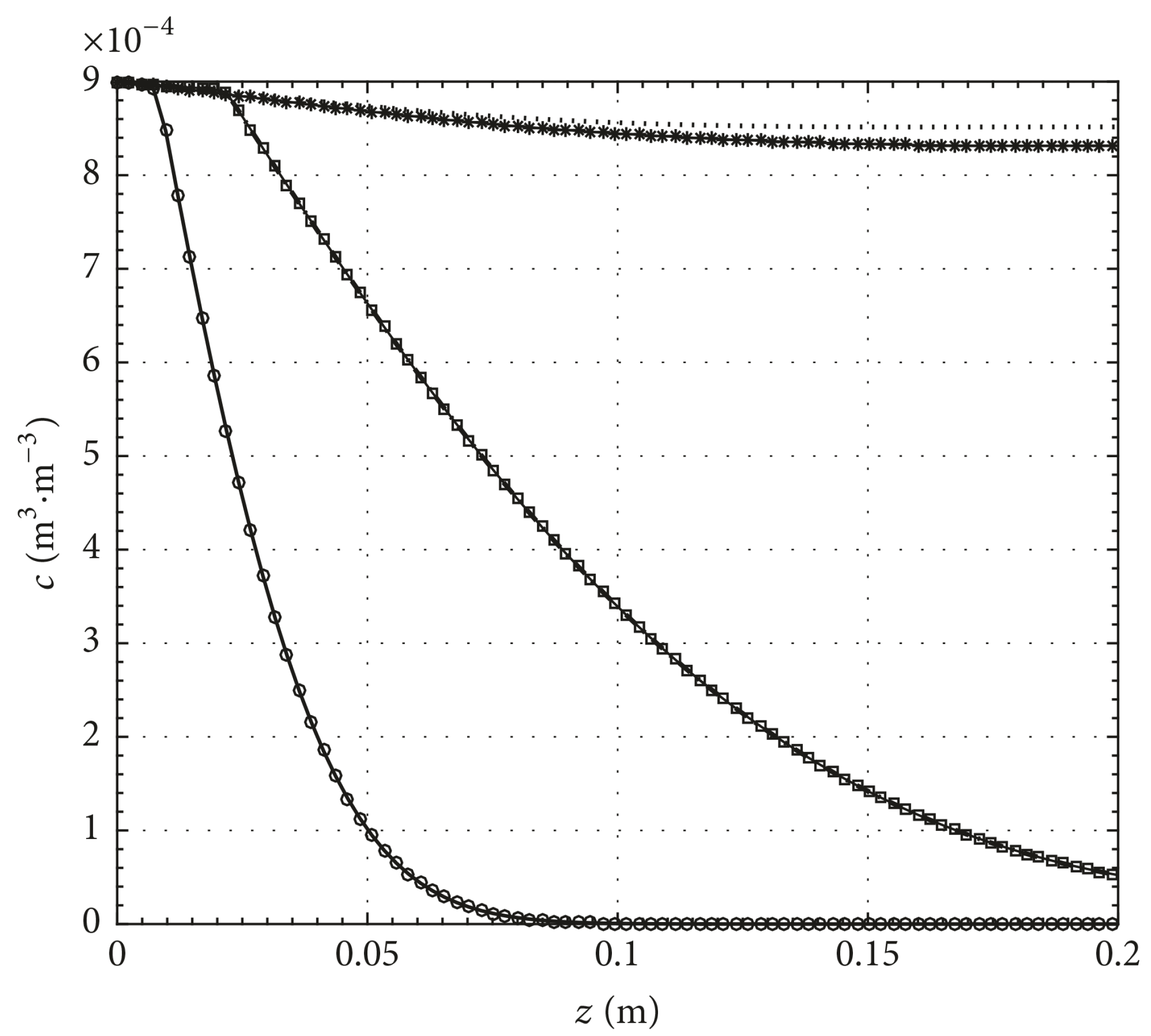
The above model is solved using the Galerkin and time integration methods. The essential outcome from this simulation is that the magnetic source area affects the physical factors of the model, which are saturation, nanoparticle concentration, porosity, and permeability, as shown in Figure 4. In light of the stream course and the area of the magnet, the magnetic field can help or contradict the stream of this two-phase framework. Such behavior can be utilized for various applications that rely upon whether the objective is to aid or postpone the infused liquid progression. As indicated by this examination, if the magnet is set alongside the no-stream boundary of the concentrated counter numerical test, the immersion of nanoparticles–water suspension increases. Besides, the convergence of nanoparticles is seen to diminish slightly, which has been ascribed to a slight increment in the testimony of nanoparticles. Then again, when the inflow/outpouring limit sets the magnet, the magnet opposes the stream of ferrofluid suspension and subsequently abates the water intrusion limit. Moreover, the nanoparticle concentration appears to increase under the impact of the magnetic field, and the saved nanoparticle fixation diminishes. Both porosity and porousness are lessened due to nanoparticle adherence to the dividers of the porous media.
3.5. Modeling the Ionic Effect of Nanoparticles
When nanoparticles are inserted in the reservoir, apart from the physical phenomena there can be physiochemical interactions that exist across nanoparticles along with the pore walls, which can affect the flow of nanoparticles in the porous media. To predict the deposition and the rate of release of nanoparticles in the presence of physiochemical reactions, a mechanistic model was proposed by Abdelfatah et al. [56,57] based on the Derjaguin–Landau–Verwey–Overbeek (DLVO) theory for different temperatures, ionic strengths, and pH values. The authors used the modified DLVO theory and predicted the entrapment and detachment for two cases divided by Spielman and Friedlander [58] based on the DLVO energy profile: case 1 with the presence of energy barrier and case 2 without the energy barrier. The energy barrier plays an important role in nanoparticle deposition by providing resistance to the release of nanoparticles from the surface. The final governing equations of entrapment and release for both cases are given below. Equation (34) is the deposition term for case 1, Equation (35) is the release term, and Equation (36) is the deposition term for case 2, and the release term is neglected in this case due the condition of injection velocity of nanoparticles, which is less than the critical velocity:
The above equations were used to calculate the loss term and are combined with Brownian diffusion. The equations calculate the concentration of nanoparticles and use the forward time-central space method to discretize the governing equation and obtain the results. The authors also conducted a sensitivity analysis of nanoparticle size, pH, temperature, and the effect of ionic strength. Using the model, the authors concluded that small nanoparticles tend to have a higher rate of deposition. The rate of deposition decreases with every increase in pH and temperature, like in the case of silica and sandstone systems. The ionic strength also plays an important role in the deposition rate of nanoparticles. To study the effect of the ionic strength on the retention and transportation of nanoparticles in porous media by considering the specific example of a reservoir consisting of dolomite core material obtained from an oil well in Kuwait and Berea sandstone, Yu et al. [59] researched nanoparticle transport in the oil field using experiments and mathematical modeling. The numerical simulation was conducted with the advection–diffusion equation to gather the transport parameters of the nanoparticles. The model equations are given from Equation (37) to Equation (40):
where is the removal rate of nanoparticles in the first-order.
The initial conditions to solve the model are
is defined as the time when the nanoparticle suspension starts to inject into the column.
The boundary conditions used to solve the model are
where is the concentration of nanoparticles at time interval i at the outlet of the system, is the initial concentration of injected nanoparticles, and q is the volumetric flux. The study concluded that the ionic strength and the multivalent ions significantly affect the transport of nanoparticles in the porous media.
4. Mathematical Modeling for Enhanced Oil Recovery from Shale Reservoir Using Nanoparticles
Shale reservoirs can be defined as extraordinary fine-grained sediments with low porosity and extremely low permeability [60,61]. As opposed to ordinary reservoirs, shale fractures usually contain four pore structures: inorganic matter, organic matter overpowered by hydrocarbon wettability, natural fractures, and hydraulic fractures. Simultaneously, hydraulic fractures and the associated reservoir volume (SRV) from induced fractures assume a basic job in essentially expanding the efficiency. A mathematical model was developed by An et al. [62,63] for magnetic nanoparticle transport in shale reservoirs by considering both micro and macro phenomena. The model used the principles of Darcy’s law, Brownian diffusion, gas diffusion and desorption, slippage flow and capillary effects in the reservoir of micro to nanopores and extremely low permeability. The above mathematical/physical principles are used for different phenomena that take place at different parts of the shale reservoir because of a change in the physical properties of the different sections of the shale reservoir. The developed model is based on the two-phase flow of gaseous and aqueous shale reservoirs. The nanoparticles are immersed only in the aqueous phase, and the gaseous phase contains natural methane gas. The flow of water is considered to be based on Darcy’s law, while the gas flow behaves differently because of the extremely low permeability of the micro and nanoscale pores. Based on Darcy’s law, gas diffusion, gas desorption, and slippage flow are also considered to explain the gas transport in shale reservoirs [62]. As the size of nanoparticles is less—about 30–80 nm—the flow is considered to be based on Brownian diffusion and convection. To study nanoparticle transport in a shale reservoir, the following assumptions were made by the authors: (1) nanoparticles can flow only in aqueous medium; hence, there is no nanoparticle concentration in the gaseous phase; (2) intercommunication between nanoparticles and the reservoir matrix is considered to be zero (also, nanoparticle deposition is explicated). The governing equations used in the model are given below as Equation (41) to Equation (43):
where l represent the water or gaseous phase, represents the concentration of the nanoparticle deposition I, represents the flux of component I, stands for the source or sink of component I, C denotes the concentration of nanoparticles, indicates the source or sink of nanoparticles, represents the diffusion coefficient of nanoparticles which are obtained from the modification of the Stokes–Einstein Equation [64], which is represented below:
The mass balance equations about fluids are applied to solve the unknown variables by employing the Newton–Raphson iteration in the mathematical model above. These continuum equations are also discretized in space using the integral finite difference method. Numerical examples performed in the work are based on an isothermal environment which means the heat transfer and the loss are considered to be negligible, so the heat transfer and loss are neglected [62,63]. The authors have built both micro models, and both the macro models and numerical simulations are performed for the models by considering the organic matter randomly distributed within the inorganic matrix. The models predicted the effect of physical parameters, such as the water saturation, grid pressure, and concentration of nanoparticles, through numerical simulations. The models concluded that nanoparticles could easily flow through the aqueous phase into the fractures, but their transport into the shale matrix is quite limited, with little transport shown into the organic matter. The authors also studied the effect of magnetization by using the magnetic nanoparticles and concluded that magnetic nanoparticles could extend the magnetic susceptibility of the reservoir. The models can be employed to gain insight into the flow of nanoparticles in the shale reservoirs, and they also will help to trace the nanoparticle movement in the shale reservoir for different nanoparticles. These are also useful for predicting the EOR efficiency and managing the cost optimization studies.
5. Challenges Ahead
The basic understanding of nanoparticle-assisted EOR is very limited, and a more fundamental and theoretical understanding of the behavior of nanoparticles in different reservoirs and under different physical conditions is required, which could be achieved by developing a more advanced mathematical model. More efficient mathematical models are based on filtration theory. Hence, more models based on the different approaches of nanoparticle flow in the porous media are needed. The literature is lacking studies of microscale mathematical models for nanoparticle flow in the porous media for applications in EOR. Microscale models can give a clear understanding of the physical interactions between the nanoparticles, rocks, fine particles, and fluid inside the reservoir, and also provides insight into the chemical reactions taking place inside the reservoir. A study combining the macro- and micro-scale models could provide a more accurate and conclusive assessment on the advantages of nanofluid-assisted EOR. A different additional mechanism is used along with nanoparticles in EOR applications like electromagnetic heating and magnetic fields. So, it is also vital to study the behavior of nanoparticles in the presence of electromagnetic waves in the reservoir and heat transfer between nanoparticles, oil, and water in the reservoir.
6. Conclusions
A detailed review of the modeling of nanoparticle-assisted EOR was presented in this paper. The first section explained the flow of nanoparticles in porous media. The flow of nanoparticles in porous media can be governed by Brownian diffusion. The next section reviewed the multiphase flow models which are used to assess nanoparticle behaviour in the reservoir. Nanoparticles are useful as EOR agents because of their size, ability to change the interfacial tension, porosity, and wettability in the reservoir. They are also a better carrier of heat transfer. As such, this can also be used to heat the reservoir to improve the oil recovery. The first section of the modeling explained the flow of nanoparticles in porous media followed by a review of multiphase flow by considering nanoparticles in the reservoir. The subsequent sections considered the flow characteristics, physical phenomena, and reservoir types. The models show that the physical properties of nanoparticles such as size, permeability, and interaction with external fields, as well as the type of material, play essential roles in EOR applications. As discussed in the challenges ahead section, a study should be done on them, and a pilot experimental study should also be carried out, which could help to apply nanoparticle-assisted EOR in the oil and gas industry.
Author Contributions
Concept and writing S.A.I. and A.S.; Review of manuscript and modification S.A.I., A.S., N.Y. and N.Z.
Funding
This research was funded by YUTP (Cost Center No: 0153AA-E26) grant scheme.
Acknowledgments
The authors would like to offer their profoundest gratitude to Universiti Teknologi PETRONAS, Malaysia for providing a congenial work environment and the state-of-the-art research facilities. The research grant has extended to us by the YUTP (Cost Center No: 0153AA-E26) for ongoing research projects.
Conflicts of Interest
The authors declare no conflict of interest.
Abbreviations
The following abbreviations are used in this manuscript:
| EM | Electromagnetic |
| EOR | Enhanced Oil Recovery |
| NPs | Nanoparticles |
| OOIP | Original Oil in Place |
| IMPES | Implicit Pressure and Explicit Saturation |
Nomenclature
| Concentration of the nanoparticles | |
| t | Time |
| Porosity | |
| D | Dispersion |
| R | Loss Term |
| l | Phase |
| Coefficient of surface retention | |
| Coefficient of surface entrainment | |
| Coefficient of pore throat blocking | |
| Critical velocity of the phase for entrain particles |
References
- Patel, J.; Borgohain, S.; Kumar, M.; Rangarajan, V.; Somasundaran, P.; Sen, R. Recent developments in microbial enhanced oil recovery. Renew. Sustain. Energy Rev. 2015, 52, 1539–1558. [Google Scholar] [CrossRef]
- Agista, M.; Guo, K.; Yu, Z. A state-of-the-art review of nanoparticles application in petroleum with a focus on enhanced oil recovery. Appl. Sci. 2018, 8, 871. [Google Scholar] [CrossRef]
- Adil, M.; Lee, K.; Mohd Zaid, H.; Ahmad Latiff, N.R.; Alnarabiji, M.S. Experimental study on electromagnetic-assisted ZnO nanofluid flooding for enhanced oil recovery (EOR). PLoS ONE 2018, 13, e0193518. [Google Scholar] [CrossRef] [PubMed]
- Sun, X.; Zhang, Y.; Chen, G.; Gai, Z. Application of nanoparticles in enhanced oil recovery: A critical review of recent progress. Energies 2017, 10, 345. [Google Scholar] [CrossRef]
- Alvarado, V.; Manrique, E. Enhanced oil recovery: An update review. Energies 2010, 3, 1529–1575. [Google Scholar] [CrossRef]
- Krishnamoorti, R. Extracting the benefits of nanotechnology for the oil Industry. J. Pet. Technol. 2006, 58, 24–26. [Google Scholar] [CrossRef]
- Negin, C.; Ali, S.; Xie, Q. Application of nanotechnology for enhancing oil recovery—A review. Petroleum 2016, 2, 324–333. [Google Scholar] [CrossRef]
- Cheraghian, G.; Hendraningrat, L. A review on applications of nanotechnology in the enhanced oil recovery part A: Effects of nanoparticles on interfacial tension. Int. Nano Lett. 2016, 6, 129–138. [Google Scholar] [CrossRef]
- Cheraghian, G.; Hendraningrat, L. A review on applications of nanotechnology in the enhanced oil recovery part B: Effects of nanoparticles on flooding. Int. Nano Lett. 2016, 6, 1–10. [Google Scholar] [CrossRef]
- Kasaeian, A.; Azarian, R.D.; Mahian, O.; Kolsi, L.; Chamkha, A.J.; Wongwises, S.; Pop, I. Nanofluid flow and heat transfer in porous media: A review of the latest developments. Int. J. Heat Mass Transf. 2017, 107, 778–791. [Google Scholar] [CrossRef]
- Lau, H.C.; Yu, M.; Nguyen, Q.P. Nanotechnology for oilfield applications: Challenges and impact. J. Pet. Sci. Eng. 2017, 157, 1160–1169. [Google Scholar] [CrossRef]
- Peng, B.; Zhang, L.; Luo, J.; Wang, P.; Ding, B.; Zeng, M.; Cheng, Z. A review of nanomaterials for nanofluid enhanced oil recovery. RSC Adv. 2017, 7, 32246–32254. [Google Scholar] [CrossRef] [Green Version]
- McDowell-Boyer, L.M.; Hunt, J.R.; Sitar, N. Particle transport through porous media. Water Resour. Res. 1986, 22, 1901–1921. [Google Scholar] [CrossRef]
- Petosa, A.R.; Jaisi, D.P.; Quevedo, I.R.; Elimelech, M.; Tufenkji, N. Aggregation and deposition of engineered nanomaterials in aquatic environments: Role of physicochemical interactions. Environ. Sci. Technol. 2010, 44, 6532–6549. [Google Scholar] [CrossRef]
- Salama, A.; Negara, S.; El Amin, M.; Sun, S. Numerical investigation of nanoparticles transport in anisotropic porous media. J. Contam. Hydrol. 2015, 181, 114–130. [Google Scholar] [CrossRef] [Green Version]
- Rajagopalan, R.; Tien, C. Trajectory analysis of deep-bed filtration with the sphere-in-cell porous media model. AIChE J. 1976, 22, 523–533. [Google Scholar] [CrossRef]
- Yao, K.-M.; Habibian, M.T.; O’Melia, C.R. Water and waste water filtration. Concepts and applications. Environ. Sci. Technol. 1971, 5, 1105–1112. [Google Scholar] [CrossRef]
- Pham, N.H.; Swatske, D.P.; Harwell, J.H.; Shiau, B.J.; Papavassiliou, D.V. Transport of nanoparticles and kinetics in packed beds: A numerical approach with lattice Boltzmann simulations and particle tracking. Int. J. Heat Mass Transf. 2014, 72, 319–328. [Google Scholar] [CrossRef]
- Goldberg, E.; Scheringer, M.; Bucheli, T.D.; Hungerbühler, K. Critical assessment of models for transport of engineered nanoparticles in saturated porous media. Environ. Sci. Technol. 2014, 48, 12732–12741. [Google Scholar] [CrossRef]
- Ju, B.; Fan, T. Experimental study and mathematical model of nanoparticle transport in porous media. Powder Technol. 2009, 192, 195–202. [Google Scholar] [CrossRef]
- Ju, B.; Dai, S.; Luan, Z.; Zhu, T.; Su, X.; Qiu, X. A study of wettability and permeability change caused by adsorption of nanometer structured polysilicon on the surface of porous media. In Proceedings of the SPE Asia Pacific Oil and Gas Conference and Exhibition, Melbourne, Australia, 8–10 October 2002; pp. 915–956. [Google Scholar]
- Gruesbeck, C.; Collins, R.E. Entrainment and deposition of fine particles in porous media. Soc. Pet. Eng. J. 1982, 22, 847–856. [Google Scholar] [CrossRef]
- Sepehri, M.; Moradi, B.; Emamzadeh, A.; Mohammadi, A.H. Experimental study and numerical modeling for enhancing oil recovery from carbonate reservoirs by nanoparticle flooding. Oil Gas Sci. Technol. Rev. d’IFP Energ. Nouv. 2019, 74. [Google Scholar] [CrossRef]
- Cullen, E.; O’Carroll, D.M.; Yanful, E.K.; Sleep, B. Simulation of the subsurface mobility of carbon nanoparticles at the field scale. Adv. Water Resour. 2010, 33, 361–371. [Google Scholar] [CrossRef]
- Bradford, S.A.; Yates, S.R.; Bettahar, M.; Simunek, J. Physical factors affecting the transport and fate of colloids in saturated porous media. Water Resour. Res. 2002, 38. [Google Scholar] [CrossRef]
- Zhang, T.; Murphy, M.; Yu, H.; Huh, C.; Bryant, S.L. Mechanistic model for nanoparticle retention in porous media. Transp. Porous Media 2016, 115, 387–406. [Google Scholar] [CrossRef]
- Madhan, N.A. A Literature Review and Transport Modelling of Nanoparticles for Enhanced Oil Recovery. Master’s Thesis, University of Stavanger, Stavanger, Norway, July 2017. [Google Scholar]
- Tufenkji, N.; Elimelech, M. Correlation equation for predicting single-collector efficiency in physicochemical filtration in saturated porous media. Environ. Sci. Technol. 2004, 28, 529–536. [Google Scholar] [CrossRef]
- Li, Y.; Wang, Y.; Pennell, K.D.; Abriola, L.M. Investigation of the transport and deposition of fullerene (C60) nanoparticles in quartz sands under varying flow conditions. Environ. Sci. Technol. 2008, 42, 7174–7180. [Google Scholar] [CrossRef]
- Liu, X.; O’Carroll, D.M.; Petersen, E.J.; Huang, Q.; Anderson, C.L. Mobility of multiwalled carbon nanotubes in porous media. Environ. Sci. Technol. 2009, 43, 8153–8158. [Google Scholar] [CrossRef]
- Wang, Y.; Li, Y.; Fortner, J.D.; Hughes, J.B.; Abriola, L.M.; Pennell, K.D. Transport and retention of nanoscale C60 aggregates in water-saturated porous media. Environ. Sci. Technol. 2008, 42, 3588–3594. [Google Scholar] [CrossRef]
- Li, Z. Modeling and Simulation of Polymer Flooding Including the Effects of Fracturing. Ph.D. Thesis, The University of Texas at Austin, Austin, TX, USA, 2015. [Google Scholar]
- Santoso, R.K.; Rachmat, S.; Putra, W.D.K.; Resha, A.H.; Hartowo, H. Numerical modeling of nanoparticles transport in porous media for optimisation in well stimulation and EOR using electromagnetic heating. In Proceedings of the SPE Asia Pacific Oil and Gas Conference and Exhibition, Perth, Australia, 25–27 October 2016. [Google Scholar]
- Santoso, R.K.; Rachmat, S.; Putra, W.D.K.; Resha, A.H.; Hartowo, H. Transport and retention modelling of iron oxide nanoparticles in core scale porous media for electromagnetic heating well-stimulation optimization. IOP Conf. Ser. Mater. Sci. Eng. 2017, 214, 012017. [Google Scholar] [CrossRef]
- Santoso, R.K.; Rachmat, S.; Resha, A.H.; Putra, W.D.K.; Hartowo, H.; Setiawati, O. An investigation of Fe2O3 nanoparticles diffusion into oil for heat transfer optimisation on electromagnetic heating for well stimulation and EOR. In SPE Asia Pacific Oil & Gas Conference and Exhibition; Society of Petroleum Engineers: Richardson, TX, USA, 2016. [Google Scholar]
- Zhang, T. Modeling of Nanoparticle Transport in Porous Media. Ph.D. Thesis, The University of Texas at Austin, Austin, TX, USA, 2012. [Google Scholar]
- Chen, H.; Di, Q.; Ye, F.; Gu, C.; Zhang, J. Numerical simulation of drag reduction effects by hydrophobic nanoparticles adsorption method in water flooding processes. J. Nat. Gas Sci. Eng. 2016, 35, 1261–1269. [Google Scholar] [CrossRef]
- Abdelfatah, E.; Pournik, M.; Shiau, B.J.B.; Harwell, J. Mathematical modeling and simulation of nanoparticles transport in heterogeneous porous media. J. Nat. Gas Sci. Eng. 2017, 40, 1–16. [Google Scholar] [CrossRef]
- El-Amin, M.F.; Salama, A.; Sun, S. Numerical and dimensional analysis of nanoparticles transport with two-phase flow in porous media. J. Pet. Sci. Eng. 2015, 128, 53–64. [Google Scholar] [CrossRef]
- El-Amin, M.F.; Salama, A.; Sun, S. Modeling and simulation of nanoparticles transport in a two-phase flow in porous media. In Proceedings of the SPE International Oilfield Nanotechnology Conference, Noordwijk, The Netherlands, 12–14 June 2012; pp. 1–9. [Google Scholar]
- El-Amin, M.F.; Sun, S.; Salama, A. Modeling and simulation of nanoparticle transport in multiphase flows in porous media: CO2 sequestration. In Proceedings of the Mathematical Methods in Fluid Dynamics and Simulation of Giant Oil and Gas Reservoirs, Istanbul, Turkey, 3–5 September 2012; pp. 1–10. [Google Scholar]
- El-Amin, M.F.; Kou, J.; Sun, S.; Salama, A. Numerical modeling of nanoparticles transport with two-phase flow in porous media using iterative implicit method. arXiv 2013, arXiv:1310.4769. [Google Scholar]
- El-Amin, M.F.; Kou, J.; Sun, S.; Salama, A. An iterative implicit scheme for nanoparticles transport with two-phase flow in porous media. Procedia Comput. Sci. 2016, 80, 1344–1353. [Google Scholar] [CrossRef]
- El-Amin, M.F.; Sun, S.; Salama, A. Enhanced oil recovery by nanoparticles injection: Modeling and simulation. In Proceedings of the SPE Middle East Oil and Gas Show and Conference, Manama, Bahrain, 10–13 March 2013; Society of Petroleum Engineers: Richardson, TX, USA, 2013; pp. 10–13. [Google Scholar]
- Bedrikovetsky, P.; Santos, A.; Siqueira, A.; Souza, A.L.; Shecaira, F. A stochastic model for deep bed filtration and well impairment. In Proceedings of the SPE European Formation Damage Conference, The Hague, The Netherlands, 13–14 May 2003. [Google Scholar]
- Benamar, A.; Nasre-Dine, A.; Wang, H.Q.; Alem, A. Particle transport in a saturated porous medium: Pore structure effects. Comptes Rendus Geosci. 2007, 339, 674–681. [Google Scholar] [CrossRef]
- He, F.; Zhang, M.; Qian, T.; Zhao, D. Transport of carboxymethyl cellulose stabilized iron nanoparticles in porous media: Column experiments and modeling. J. Coll. Interface Sci. 2009, 334, 96–102. [Google Scholar] [CrossRef]
- El-Amin, M.F.; Kou, J.; Sun, S. Discrete-fracture-model of multi-scale time-splitting two-phase flow including nanoparticles transport in fractured porous media. J. Comput. Appl. Math. 2018, 333, 327–349. [Google Scholar] [CrossRef]
- El-Amin, M.F.; Kou, J.; Sun, S. A multiscale time-splitting discrete fracture model of nanoparticles transport in fractured porous media. In Proceedings of the SPE Kingdom of Saudi Arabia Annual Technical Symposium and Exhibition, Dammam, Saudi Arabia, 24–27 April 2017. [Google Scholar]
- Aderibigbe, A.A.; Cheng, K.; Heidari, Z.; Killough, J.E.; Fuss, T.; Stephens, W. Detection of propping agents in fractures using magnetic ausceptibility measurements enhanced by magnetic nanoparticles. In Proceedings of the SPE Annual Technical Conference and Exhibition, Amsterdam, The Netherlands, 27–29 October 2014; pp. 27–29. [Google Scholar]
- El-Amin, M.F.; Saad, A.M.; Sun, S. Modeling and analysis of magnetic nanoparticles injection in water-oil two-phase flow in porous media under magnetic field effect. Geofluids 2017, 2017, 1–12. [Google Scholar] [CrossRef]
- El-Amin, M.F.; Saad, A.M.; Sun, S.; Salama, A. Numerical simulation of magnetic nanoparticles injection into two-phase flow in a porous medium. Procedia Comput. Sci. 2017, 108, 2260–2264. [Google Scholar] [CrossRef]
- El-Amin, M.F.; Brahimi, T. Numerical modeling of magnetic nanoparticles transport in a two-phase flow in porous media. In Proceedings of the SPE Reservoir Characterization and Simulation Conference and Exhibition, Abu Dhabi, UAE, 8–10 May 2017. [Google Scholar]
- MacCaig, M. Permanent Magnets in Theory and Practice; Pentech Press: London, UK, 1987. [Google Scholar]
- Oldenburg, C.M.; Borglin, S.E.; Moridis, G.J. Numerical simulation of ferrofluid flow for subsurface environmental engineering applications. Transp. Porous Media 2000, 38, 319–344. [Google Scholar] [CrossRef]
- Abdelfatah, E.R.; Kang, K.; Pournik, M.; Shiau, B.; Harwell, J.; Haroun, M.R.; Rahman, M.M. Study of nanoparticle adsorption and release in porous media based on the DLVO theory. In Proceedings of the SPE Latin America and Caribbean Petroleum Engineering Conference, Buenos Aires, Argentina, 17–19 May 2017. [Google Scholar]
- Abdelfatah, E.R.; Kang, K.; Pournik, M.; Shiau, B.J.B.; Harwell, J. Mechanistic study of nanoparticles deposition and release in porous media. J. Pet. Sci. Eng. 2017, 157, 816–832. [Google Scholar] [CrossRef]
- Spielman, L.A.; Friedlander, S.K. Role of the electrical double layer in particle deposition by convective diffusion. J. Colloid Interface Sci. 1974, 46, 22–31. [Google Scholar] [CrossRef]
- Yu, J.; Berlin, J.B.; Lu, W.; Zhang, L.; Kan, A.T.; Zhang, P.; Walsh, E.E.; Work, S.; Chen, W.; Tour, J.; et al. Transport study of nanoparticles for oilfield application. In Proceedings of the SPE International Conference on Oilfield Scale, Aberdeen, Scotland, UK, 20–21 June 2010; pp. 2–4. [Google Scholar]
- Cipolla, C.L.; Lolon, E.P.; Erdle, J.C.; Rubin, B. Reservoir modeling in shale-gas reservoirs. SPE Reserv. Eval. Eng. 2010, 13, 638–653. [Google Scholar] [CrossRef]
- Javadpour, F. Nanopores and apparent permeability of gas flow in mudrocks (shales and siltstone). J. Can. Pet. Technol. 2009, 48, 16–21. [Google Scholar] [CrossRef]
- An, C.; Alfi, M.; Yan, B.; Cheng, K.; Heidari, Z.; Killough, J.E. SPE-173282-MS modeling of magnetic nanoparticle transport in shale reservoirs. In Proceedings of the the SPE Reservoir Simulation Symposium, Houston, TX, USA, 23–25 February 2015. [Google Scholar]
- An, C.; Alfi, M.; Yan, B.; Killough, J.E. A new study of magnetic nanoparticle transport and quantifying magnetization analysis in fractured shale reservoir using numerical modeling. J. Nat. Gas Sci. Eng. 2016, 28, 502–521. [Google Scholar] [CrossRef]
- Millington, R.J.; Quirk, J.P. Permeability of porous solids. Trans. Faraday Soc. (R. Soc. Chem.) 1961, 57, 1200–1207. [Google Scholar] [CrossRef]
Figure 1.
Different categories of Enhanced Oil Recovery (EOR) techniques [4].
Figure 1.
Different categories of Enhanced Oil Recovery (EOR) techniques [4].

Figure 2.
Research on nanotechnology application in the petroleum industry [2].
Figure 2.
Research on nanotechnology application in the petroleum industry [2].

Figure 3.
The three filtration mechanisms generally considered. Note the particle size dependence and differences in deposit morphology [13].
Figure 3.
The three filtration mechanisms generally considered. Note the particle size dependence and differences in deposit morphology [13].

Figure 4.
Nanoparticle concentration versus core length with and without the magnetic field effect for various values of imbibition time. The magnet is placed on the left side of the core [51].
Figure 4.
Nanoparticle concentration versus core length with and without the magnetic field effect for various values of imbibition time. The magnet is placed on the left side of the core [51].


| Model | Deposition Term | Fitting Parameter | Reference |
|---|---|---|---|
| Colloid Filtration Model | , | Yao et al. [17], Tufenkji and Elimelech [28] | |
| Filtration Model with Site Blocking | Li et al. [29], Cullen et al. [24], Liu et al. [30] | ||
| Filtration Model with Detachment | Bradford et al. [25] | ||
| Kinetic Langmuir Model | Wang et al. [31] | ||
| Independent Two Site Model (ITSM) | Zhang et al. [26,32] |
© 2019 by the authors. Licensee MDPI, Basel, Switzerland. This article is an open access article distributed under the terms and conditions of the Creative Commons Attribution (CC BY) license (http://creativecommons.org/licenses/by/4.0/).
Share and Cite
MDPI and ACS Style
Irfan, S.A.; Shafie, A.; Yahya, N.; Zainuddin, N. Mathematical Modeling and Simulation of Nanoparticle-Assisted Enhanced Oil Recovery—A Review. Energies 2019, 12, 1575. https://doi.org/10.3390/en12081575
AMA Style
Irfan SA, Shafie A, Yahya N, Zainuddin N. Mathematical Modeling and Simulation of Nanoparticle-Assisted Enhanced Oil Recovery—A Review. Energies. 2019; 12(8):1575. https://doi.org/10.3390/en12081575
Chicago/Turabian StyleIrfan, Sayed Ameenuddin, Afza Shafie, Noorhana Yahya, and Nooraini Zainuddin. 2019. "Mathematical Modeling and Simulation of Nanoparticle-Assisted Enhanced Oil Recovery—A Review" Energies 12, no. 8: 1575. https://doi.org/10.3390/en12081575
Note that from the first issue of 2016, this journal uses article numbers instead of page numbers. See further details here.