Article

Future Fuels—Analyses of the Future Prospects of Renewable Synthetic Fuels

by
Thomas Pregger
1,
Günter Schiller
1,
Felix Cebulla
1,
Ralph-Uwe Dietrich
1,
Simon Maier
1,
André Thess
1,
Andreas Lischke
2,
Nathalie Monnerie
3,
Christian Sattler
3,
Patrick Le Clercq
4,
Bastian Rauch
4,
Markus Köhler
4,
Michael Severin
4,
Peter Kutne
4,
Christiane Voigt
5,
Hans Schlager
5,
Simone Ehrenberger
6,
Mario Feinauer
6,
Lukas Werling
7,
Victor P. Zhukov
7,
Christoph Kirchberger
7,
Helmut K. Ciezki
7,
Florian Linke
8,
Torsten Methling
4,*,
Uwe Riedel
4 and
Manfred Aigner
4
add Show full author list remove Hide full author list
1
Institute of Engineering Thermodynamics, German Aerospace Center (DLR), Pfaffenwaldring 38-40, 70569 Stuttgart, Germany
2
Institute of Transport Research, German Aerospace Center (DLR), Rudower Chaussee 7, 12489 Berlin, Germany
3
Institute of Solar Research, German Aerospace Center (DLR), Linder Höhe, 51147 Köln, Germany
4
Institute of Combustion Technology, German Aerospace Center (DLR), Pfaffenwaldring 38-40, 70569 Stuttgart, Germany
5
Institute of Atmospheric Physics, German Aerospace Center (DLR), Münchener Straße 20, 82234 Weßling, Germany
6
Institute of Vehicle Concepts, German Aerospace Center (DLR), Pfaffenwaldring 38-40, 70569 Stuttgart, Germany
7
Institute of Space Propulsion, German Aerospace Center (DLR), Im Langen Grund, 74239 Hardthausen, Germany
8
Air Transportation Systems, German Aerospace Center (DLR), Blohmstraße 20, 21079 Hamburg, Germany
*
Author to whom correspondence should be addressed.
Energies 2020, 13(1), 138; https://doi.org/10.3390/en13010138
Submission received: 30 September 2019 / Revised: 4 December 2019 / Accepted: 19 December 2019 / Published: 26 December 2019
(This article belongs to the Special Issue Materials and Devices for Solar to Hydrogen Energy Conversion)

Abstract

:
The Future Fuels project combines research in several institutes of the German Aerospace Center (DLR) on the production and use of synthetic fuels for space, energy, transportation, and aviation. This article gives an overview of the research questions considered and results achieved so far and also provides insight into the multidimensional and interdisciplinary project approach. Various methods and models were used which are embedded in the research context and based on established approaches. The prospects for large-scale fuel production using renewable electricity and solar radiation played a key role in the project. Empirical and model-based investigations of the technological and cost-related aspects were supplemented by modelling of the integration into a future electricity system. The composition, properties, and the related performance and emissions of synthetic fuels play an important role both for potential oxygenated drop-in fuels in road transport and for the design and certification of alternative aviation fuels. In addition, possible green synthetic fuels as an alternative to highly toxic hydrazine were investigated with different tools and experiments using combustion chambers. The results provide new answers to many research questions. The experiences with the interdisciplinary approach of Future Fuels are relevant for the further development of research topics and co-operations in this field.

1. Introduction

Synthetic fuels based on renewable energies (RE) are widely seen as a key element to achieving climate-neutral transport (e.g., [1,2]). As liquid hydrocarbons have a high energy and power density, they are primarily discussed as fuels for (heavy) road vehicles, ships, and aircraft. Due to their low storage and transport losses, they are also conceivable as a complementary long-term electricity storage option [3]. The challenges of producing and implementing these fuels are manifold. Chemical processes and renewable electrical or thermal energy can be used to produce liquid hydrocarbons from various carbon sources and hydrogen (and sometimes oxygen). Synthetic fuels have several advantages: they can be easily integrated into our existing energy and mobility infrastructures, can be used in all areas of the transport sector, and they can be optimized with regard to their chemical properties. The main disadvantages are the high energy losses and production costs.
In this research context, eleven research groups at the German Aerospace Center (DLR) are working together on the Future Fuels project on synthetic fuels. The aim of the interdisciplinary approach is to realize synergies and joint research activities, as well as new research impulses through different perspectives. The scientists and engineers are investigating how synthetic fuels can be produced using solar energy and electrolysis processes (Solar Fuels), and are developing concepts for the re-conversion of these fuels into electricity. They are working on emission-optimized fuels for transport and aviation (Designer Fuels), as well as advanced space applications to replace the highly toxic hydrazine (Green Propellants). Technology assessment and systems analysis are carried out, taking a holistic view of future fuels and including factors such as cost-effectiveness, performance, security of supply, and social acceptance. Under the common topic of synthetic fuels, the project thus addresses very different scientific questions, which we discuss in this article in an overall view. Different methods will be further developed and used for various experimental and analytical tasks. Since the project has already started with a first phase between the beginning of 2015 and the end of 2017, exemplary results can be shown in all research areas. Further work will be completed by the end of 2021. Most of the work focuses on the situation in Germany, but the results also have significance for other regions of the world.
An integrative part of the project represents the work on technology assessment and systems analysis, which establishes a close link between energy, transport, and aviation research. The research questions of technology assessment address the expected costs and carbon dioxide (CO2) emissions of different alternative production routes depending on technical and economic boundary conditions. Techno-economic bottom-up modelling of process routes is combined with state-of-the-art cost estimations in a systematic approach [4]. The system analysis addresses interactions of a possible national production infrastructure with the future power system and the question of the possibility of a largely renewable electricity generation for the synthesis of fuels. To this end, scenario-based modelling of future power systems is carried out using an energy system model with temporal and spatial resolution developed at DLR [5].
Another subproject focuses on the generation of solar fuels in the Earth’s sunbelt as a possible import option for Europe and other countries in the long-term. Solar thermochemical redox cycles and high-temperature electrolysis with integration of solar heat are promising processes for the production of hydrogen or syngas, which can be further processed into synthetic fuels. The coupling of a commercial high-temperature steam electrolyser with a solarthermal steam generator has been demonstrated for the first time [6].
The third subproject investigates the role of synthetic fuels as designer fuels for aviation. The work focuses on fuel specifications, as well as criteria and concepts for the design of alternative aviation turbine fuels. Density, kinematic viscosity, and net combustion heat are properties with a direct effect on combustion performance issues (also termed figures of merit) [7]. Soot emissions also partly depend on the fuel composition and are here envisaged as a further criterion for fuel design.
Subproject four focuses on the possible role for oxygenated fuels in road transportation. The research work highlights the properties and advantages of oxygenated fuels on the one hand, based on the review of the state of knowledge, and on the other hand by empirical and model-based investigations of combustion properties. In the further course of the project, an already developed concept for the survey of vehicle owners and drivers will be implemented in order to investigate the acceptance of synthetic drop-in fuels in road traffic.
Finally, subproject five addresses research and technology development activities with green propellants for space flight applications and launchers. Three different propellant system candidates were investigated. The selection was conducted under the premise that each of them shall be used in a specific mission scenario and task. Moreover, performance, low costs, environmentally friendliness, and safe handling characteristics are essential selection criteria. The relevant literature’s lists and surveys about green advanced rocket propellants or references to them are addressed in the Section 6.1. The objective of this sub-project is to show and elaborate the potential of these propellant systems, to develop and to comprehend combustor processes and to increase their level of technology maturity. Furthermore, focus is set on commercialization and usage, and to provide the necessary knowledge to the industry.

2. Technology Assessment and Systems Analysis

An essential strategy for the transformation of the energy system is the expansion of renewable energies in all sectors as an alternative to fossil fuels. An effective sector coupling is very relevant in this context, enabling the use of renewable electricity for heating and transport, as well as through the generation of synthetic energy carriers. Possible generation routes and efficient integration into the energy system play an important role here. Both aspects are examined in an integrative way in the first subproject of Future Fuels.

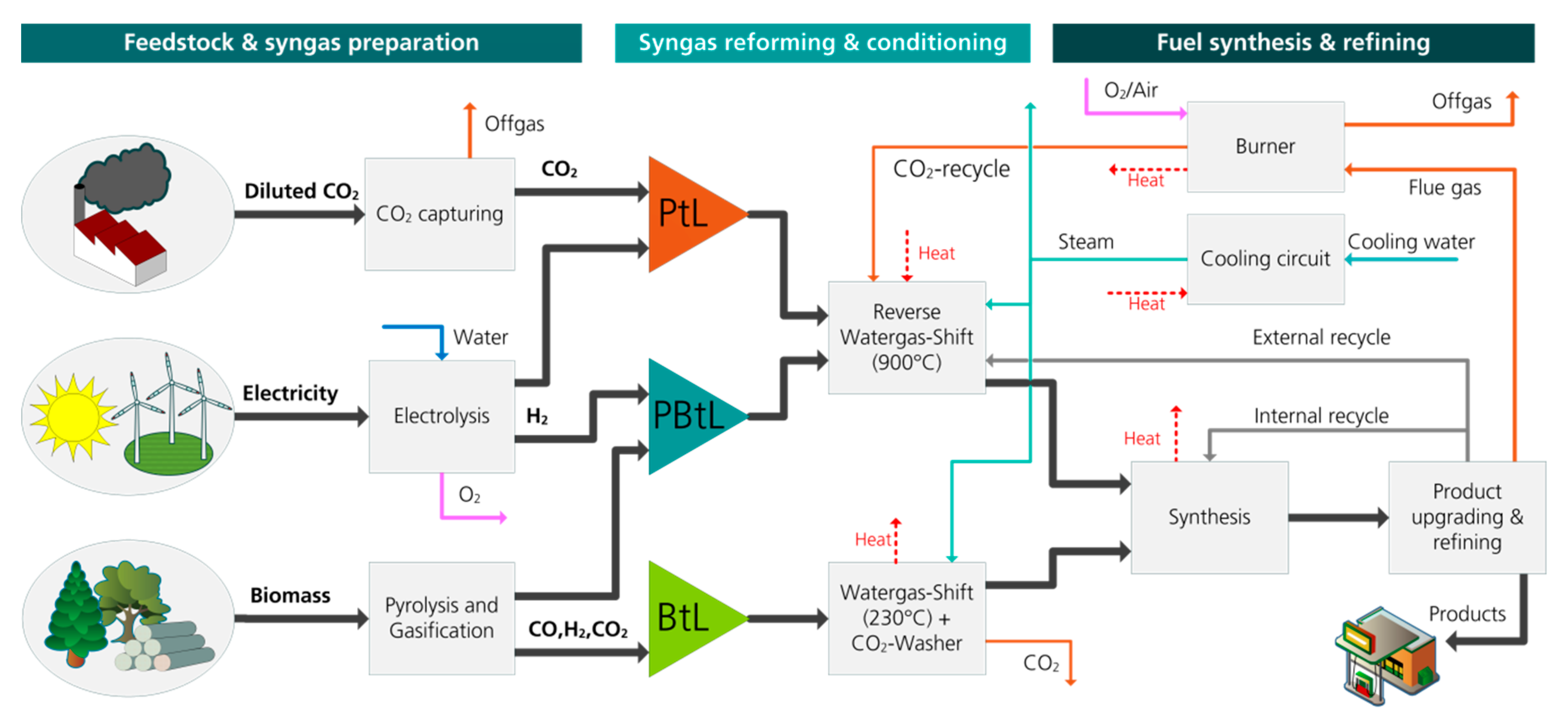
2.1. Technology Assessment of Selected Production Routes

Alternative fuels with high energy density can be produced from a variety of raw materials and energy sources. The ideal alternative fuel for low-carbon energy systems uses hydrogen and carbon from renewable sources. The production of large quantities of renewable fuels in Germany is limited by the potentials of biomass, renewable electricity, and CO2 at a high concentration. The potential of sustainably produced biomass as a carbon source is limited in Germany due to limited agricultural land for energy crops and usable residues. The potential of residual materials is seen in the order of 700–1000 PJ per year, but more than half of it has already been used to date, mainly in the heating sector [8,9]. Due to its limited potential, it appears efficient to use biomass not directly as a source for biofuels such as biodiesel or via the Biomass-to-Liquid process (BtL), but predominantly as a renewable carbon source for synthetic fuels from renewable electricity. This leads to the so-called Power & Biomass-to-Liquid concept (PBtL), in which hydrogen is produced by water electrolysis and fed into the synthesis process in order to achieve a higher fuel yield than is possible with pure biofuels [4]. Renewable electricity can also be used in Power-to-Liquid (PtL) with CO2 from the air, biogas plants, waste incineration, or other industrial waste gases as a carbon source.

2.1.1. Approach and Assumptions

For a systematic comparison of these three options, a large-scale fuel production via the Fischer–Tropsch synthesis was investigated, as Fischer–Tropsch fuels are certified synthetic blending components that can be added up to 50 percent to conventional jet fuel [10]. The block flow diagram is shown in Figure 1 for BtL, PBtL, and PtL routes. A more detailed overview of the selected process interconnections and possible alternatives is available in [4].
The techno-economic bottom-up modelling of these process routes was developed by using the commercial simulation software Aspen Plus®. Standardized cost estimates were derived from the resulting dimensioning and integration of the production plants using the Techno-Economic Process Evaluation Tool (TEPET) of DLR. A description of the methodology and a comparison with existing techno-economic studies on alternative and synthetic fuels can be found in [4]. The technical evaluation is based on the parameters fuel efficiency, overall efficiency, and carbon conversion. Fuel efficiency is defined as the amount of energy stored in liquid hydrocarbons in relation to the amount of energy input by electricity or biomass. Fuel efficiency illustrates the losses caused by the chemical transformation during the process, enabling different reaction paths to be compared. The overall efficiency also considers the use of by-products such as electricity, steam, and district heating. Carbon conversion refers to the carbon contained in the product in relation to the carbon introduced into the process. The estimation of the production costs is based on a standardized bottom-up methodology and the results of the process simulation. All apparatus parameters were determined, and the plant investments were estimated using reference values from the literature and cost curves from the chemical process industry.

2.1.2. Results

Table 1 shows the energy flows of a BtL and PBtL reference plant, which were both operated with a biomass input of 100 MWth, compared with two PtL plants which were dimensioned corresponding to the fuel yield of the BtL or PBtL plant (2.9 t/h for a small and 11 t/h for a large plant). Energy flows with a positive sign are by definition released into the environment. The fuel efficiency increased from 36.3% to 51.4% in the PBtL concept with the coupling of hydrogen into the BtL process. At the same time, the fuel yield was increased by a factor of approximately 3.8, which corresponds to a more efficient use of the available bio-based carbon by the same factor.
The production costs were calculated according to the standardized methodology described in [4], and updated to the year 2018. While the equipment costs can be updated by using the Chemical Engineering Plant Cost Index (CEPCI) of 2018 (603.1) according to [12], the raw material costs need to be retrieved from other sources and databases. Their prices are shown in Table 2. The resulting production costs for the PtL large concept were 2.47 €2018 per litre, the BtL production route was 2.41 €2018 per litre, and for the PBtL the updated production costs were 2.15 €2018 per litre fuel. The production costs of the BtL process route are mainly driven by the depreciation of the entrained flow gasifier (23%) and the biomass supply (20%). Regarding the PBtL and PtL routes, the production costs mostly depend on the electricity price (33% and 64%, respectively). Compared to fossil fuels, the production costs are approximately four times higher. More details can be found in [11].

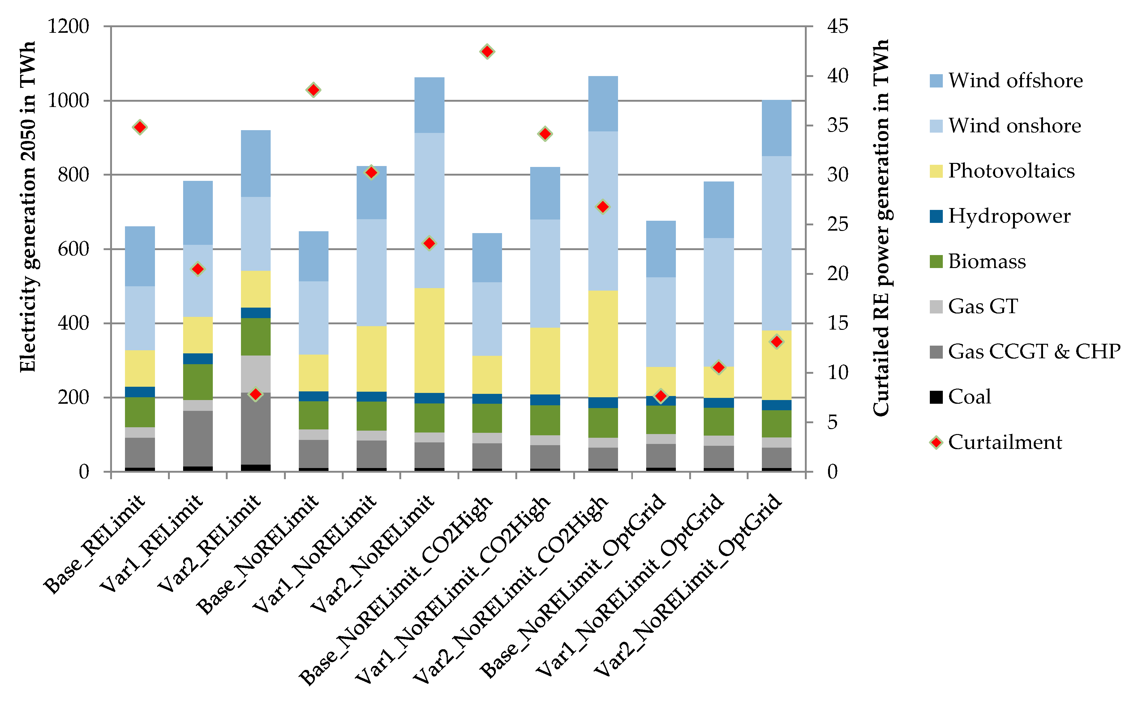
2.2. Systems Analysis of Interactions with the Power System

In addition to the open questions of possible future efficiency gains and cost degressions of synthetic fuels, the system integration also plays an important role and places additional requirements on the design and operation of process routes, especially for PtL production. This is particularly the case with an increasing expansion of variable renewable electricity generation from wind and photovoltaics (PV), which have the greatest RE potentials in Germany.

2.2.1. Approach and Assumptions

Relevant future interactions between the electricity system and a generation infrastructure for PtL or PBtL can be investigated by using a spatially and temporally resolved power system model. For its parametrisation, three demand scenarios for 2050 were defined, which differ with regard to the future electricity demand and synthetic fuel consumption in the transport sector, thereby achieving different CO2 reductions. The applied model REMix has been developed at DLR [5] and has a linear system cost minimizing approach which calculates the future electricity supply based on modelled load and feed-in time series of variable renewable power generation. For each scenario, REMix calculates capacity expansion and the hourly dispatch of power generation, storage, and transmission with an integrated optimization. The spatial resolution of the modelling divides Germany into six regions and considers the exchange of electricity with eight European regions plus North Africa via the transmission grid. It provides insights into required back-up power generation, transmission, and storage depending on assumptions about the system and essential cost parameters. RE potentials and feed-in time series were derived from satellite measurements and weather service data from the year 2006 representing approximately the average solar and wind conditions [13]. Assumptions for the necessary dimensioning of a flexible hydrogen production in Germany and relevant spatial assumptions were derived from the work of [14,15]. Investigation of the system integration of the PtL and PBtL generation is carried out with a variation of exogenously assumed CO2 emission costs in power generation of 75 versus 150 € per t CO2 (CO2High). Transmission grid transfer capacities are given exogenously in the scenarios (167 GW between all model regions) and can be increased endogenously in a variation for the further reduction of the system costs (OptGrid).
Table 3 shows the main assumptions of the three scenarios which differ regarding the overall electricity demand and the demand structure in the transport sector. The base scenario was derived from the mobility scenario Regulated Shift developed within the DLR project Transport and the Environment (VEU) [16,17]. The scenario assumes significant changes in mobility demand and modal split, so that the number of passenger cars reduces from 47 million (about 570 cars per 1000 capita) today to 35 million (460 cars per 1000 capita) in 2040. The assumed path of the German transition process in the energy system until 2050 was described in [18]. The scenario meets the target of reducing the greenhouse gas (GHG) emissions by 80% by 2050 and assumes a reduction of the electricity demand of “conventional” consumers (final energy) by a third.
The case study is based on the following additional assumptions: The RE share of electricity generation will rise to over 80% in 2050 (both in Germany and in Europe as a whole). The expansion of RE technologies for Germany in 2050 is initially given exogenously, and a variation (RELimits) assumes limited RE potentials for further expansion (values in brackets): Wind onshore: 80 (90) GW; Wind offshore: 37 (72) GW; PV: 80 (104) GW; Hydro: 5 GW. The PEM (Polymer Electrolyte Membrane) electrolyser capacities in Germany are also given exogenously: approx. 50 to 140 GW depending on the resulting hydrogen demand and assuming an average capacity utilization of 3000 full load hours per year. The scenario assumes central hydrogen production and storage in caverns in Northern and Central Germany and decentralized production and storage in pressure tanks in Southern Germany (storage capacity of tanks equal to 24 h of hydrogen generation capacity). Controlled charging was assumed for 60% of the electric vehicle fleet, thus serving as a flexibility option in the power grid. Pumped hydro storage is fixed to today’s capacity of 6.5 GW with no further expansion assumed in the future. In addition, 37 GW of fossil power generation capacity, 14 GW biomass, and 3 GW geothermal power plants were exogenously assumed in all scenarios. The model has the possibility to determine the minimum system costs by endogenously expanding additional capacities of wind, PV, gas power plants, and grid transfer capacities.

2.2.2. Results

The results of the case study provide insights into interactions between the PtL/PBtL generation infrastructure and the power system. Figure 2 shows the calculated power generation structure and the curtailment of variable electricity generation from RE (during periods when production exceeds demand) for all scenario variants. Curtailment is a key indicator that helps to understand whether RE capacities have been efficiently integrated into the energy system. The operation of a massive hydrogen production infrastructure for synthetic fuels increases the integration of RE and correspondingly reduces the curtailment rate, provided that the hydrogen production is operated flexibly. In the modelling, the electrolysis and gas storage systems have a calculated utilization of 2800 to 4800 full load hours per year. For all three scenario variants, an optimized grid expansion (OptGrid) greatly increases flexibility. In this case, the curtailments rise with an increasing electricity demand through PtL/PBtL (comparing Base with Var1 and Var2), whereas they decrease in all other cases assuming limited grid expansion due to the increasing flexibility of hydrogen production.
The scenario analysis results in a number of further findings. As expected, the assumption of limited RE potentials for wind and PV (RELimits) leads to a strong increase in electricity generation from fossil power plants and electricity imports from Europe (indicated by the low overall domestic generation) if the demand for electricity increases due to PtL/PBtL production. Furthermore, an additional expansion of gas-fired power plants by up to 10 GW in Germany was calculated. In contrast, there will be a strong expansion of renewables without limited RE potentials (NoRELimits), with a focus on PV (up to 300 GW) and wind onshore (up to 200 GW), driven by the assumed CO2 price. This expansion can be significantly reduced in the case of unlimited, optimized grid expansion (below 190 GW each for both RE technologies). By comparison, 45 GW PV and 53 GW wind onshore were installed in Germany at the end of 2018 [19]. The calculated gross electricity generation is higher than the exogenously assumed electricity demand due to grid and storage losses and curtailment. These losses were on average 5.7% of gross generation in all of the base scenarios and decrease to 4.3% in Variant 1 and 3.5% in Variant 2. Furthermore, the use of pumped hydro storage (as short-term storage) is low overall (8–10 TWh per year generation in base scenarios without RE limits) and decline with the availability of flexible hydrogen generation capacities (5–8 TWh per year in Variant 2 scenarios without RE limits). Compared to that, the use of combined cycle gas turbines (CCGT) for hydrogen re-conversion into electricity (as long-term storage) is consistently higher, depending on the expansion of the electrolysers and hydrogen storage facilities of renewables and grid transfer capacities. In the Variant 1 and Variant 2 scenarios, the use of CCGT is lower than in the base scenarios if the RE potentials are not assumed to be limited, so that CO2 emissions from electricity generation are 2% and 4% lower, respectively. High CO2 emission costs (CO2High) reduce the utilization of CCGT in favour of the pumped hydro storage.

2.3. Discussion

The techno-economic analyses provide well-founded characterizations of the current state of PtL and PBtL technology based on a bottom-up analysis. For a comprehensive and prospective assessment of different synthetic fuel generation routes, further assessment indicators have to be analysed to consider the entire life cycle and future potentials for technical development and cost degression. This is addressed in the ongoing work of the Future Fuels project.
The first results of the systems analysis clearly show that PtL/PBtL generation can make a relevant contribution to the integration of RE into the future electricity system, assuming flexible operation of the hydrogen generation and storage as interface between these two system levels. An additional benefit of all electricity-based production processes is the seasonal storage, which enables a temporal and possibly spatial balancing of energy demand and supply in an energy system characterized by variable RE sources. Moreover, uncontrolled and base-load operation of these large generation capacities would place much higher burden on the operation of the future electricity system. Further analyses will examine interactions with other flexibility options such as stationary batteries in the European electricity grid and the possible role of imports of both renewable electricity and renewable synthetic fuels. Furthermore, scenario analyses will be based on new bottom-up projections of the possible future fuel demand.
Among others, these projections will contain a global air traffic forecast that allows for the quantification of future alternative kerosene demand in Germany until 2050. Applying a comprehensive passenger air travel demand prediction and modelling system described in [20], all commercial flights departing from Germany are modelled. For this purpose, the system first determines passenger origin-destination demand based on assumptions regarding the development of certain socio-economic factors. Using a route choice sub-model, specific itineraries are calculated and the flight frequencies between airport pairs and aircraft types required are deduced. For those flights, the necessary amount of fuel is finally computed using a flight profile database, which has been prepared based on aircraft performance models from EUROCONTROL. Assuming carbon-neutral growth in aviation from 2020 as committed to by the International Air Transport Association (IATA) [21], this yields the amount of aviation fuel that needs to be substituted by future fuels.

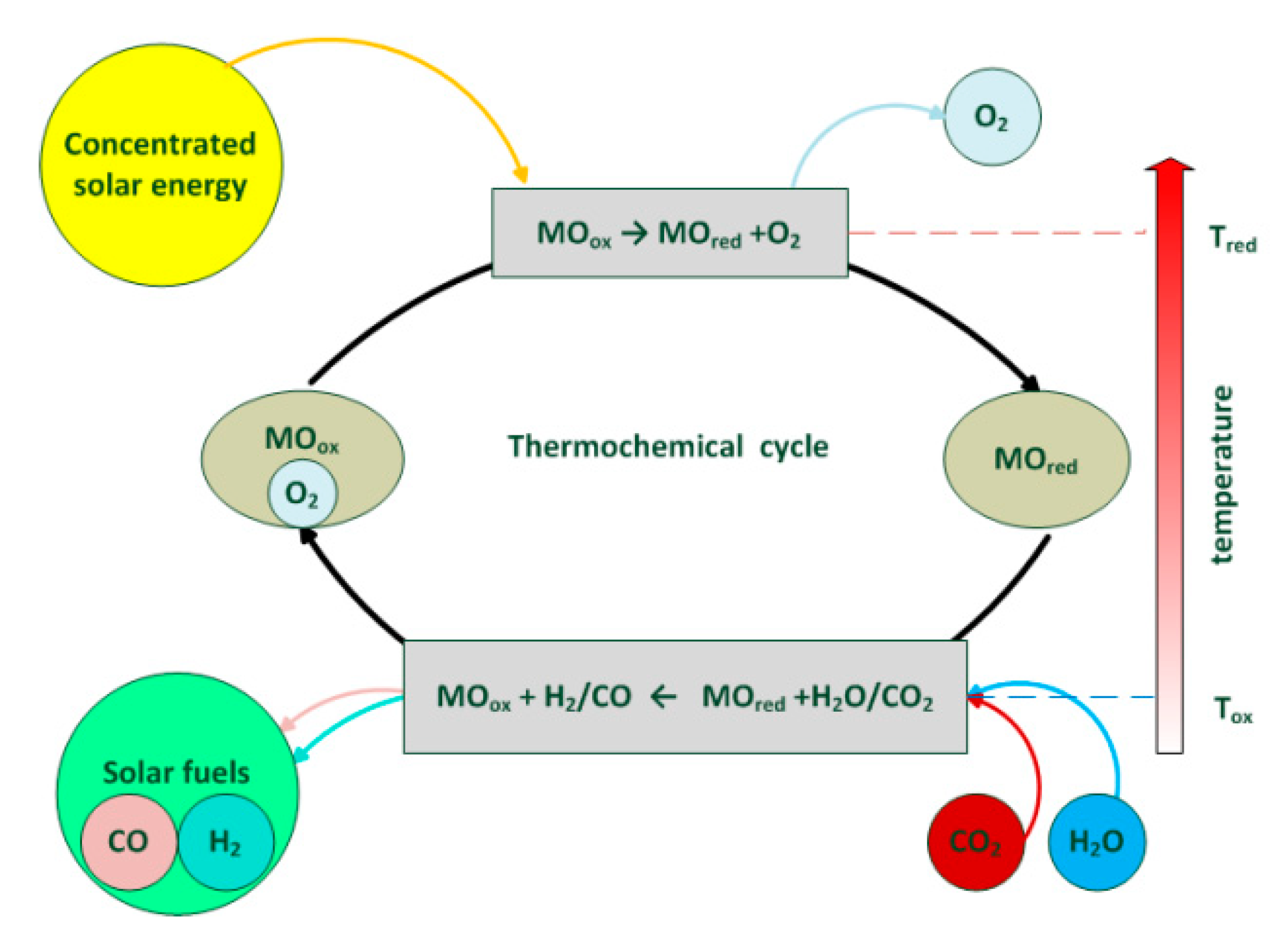
3. Solar Fuels and Reverse Power Generation

The technical challenges in the production of solar fuels are manifold and still require considerable research and development work. The work in Future Fuels focuses on the large-scale production of hydrogen or synthesis gas using solar energy as the first process step. In the case of thermochemical cycles, development work concentrates on solving material problems caused by the extreme process conditions. Further conceptual work is also required for the design of stable processes on an industrial scale. In high-temperature steam electrolysis, the energy required in order to split the water consists in electricity and heat, which can be provided by solar concentrated radiation. Reverse power generation by using synthetic fuels is a possible option for balancing variable power generation from renewable energies. Work on this topic focuses on the specific requirements for the application of synthetic fuels in a stationary gas turbine cycle.

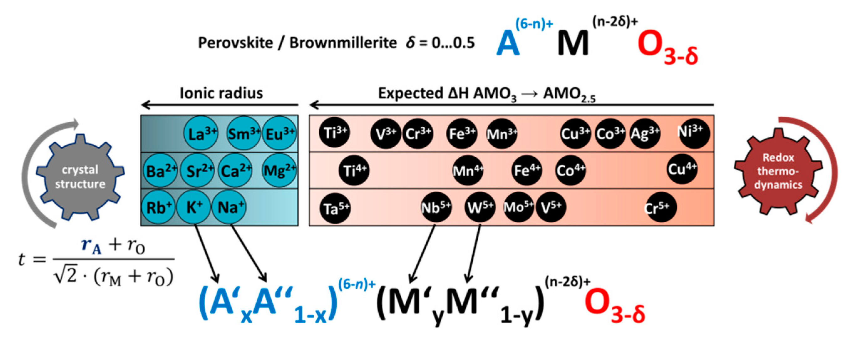
3.1. Thermochemical Cycles

Two-step thermochemical redox cycles are foreseen to be a viable alternative to state-of-the-art technology for fuels production (see e.g., [22]). Metal oxide thermochemical cycles can be coupled with concentrated solar thermal technology in order to convert solar energy into chemical energy. Combined with water splitting and/or carbon dioxide splitting, these cycles enable a route to produce solar fuels. This process is illustrated in Figure 3. In a first step at high temperature, a metal oxide is reduced. This reduced material can then be re-oxidized using water (H2O) and/or CO2, producing hydrogen (H2) or carbon monoxide (CO). The metal oxide is then reused for another reduction process while the gaseous products can be combined as synthesis gas to prepare hydrocarbons as fuels.

3.1.1. Approach and Assumptions

There are a lot of compounds which can act as redox material in thermo-chemical cycles. In order to predict the stability and response of these compounds without having to synthesize them all, a redox material simulation model must be developed. For this, perovskite has been considered as redox material. Perovskites are indeed very good candidate materials to transport oxygen in thermochemical processes with fast kinetics and stability. As their arrangement is very flexible, the adjustment of their properties is feasible [24]. A method for the design of ( A x A 1 x ) ( 6 n ) + ( M y M 1 y ) ( n 2 δ ) + O 3 δ perovskite solid solutions with two different species on the M and A sites in order to tune their redox behaviour has been developed (see Figure 4) [25]. Iterations of n values and Goldschmidt tolerance factor t [26] are made to define reliable compositions.

3.1.2. Results

The energy request of thermochemical cycles founded on perovskite materials was assessed. By creating expressions describing the dependence of the redox enthalpy and entropy variation on the oxygen non-stoichiometry δ, the equilibrium state of each of the materials can be simulated depending on the temperature and oxygen partial pressure.
Moreover, the significance of different parameters for the overall process efficiency was identified. It was shown that heat recovery efficiency is the most important factor to be optimized to increase the overall efficiency. A simulation model was developed for the determination of efficiency-enhanced redox systems. With this model, it is possible to select perovskite materials with low redox cycle energy consumption for hydrogen and synthesis gas production.

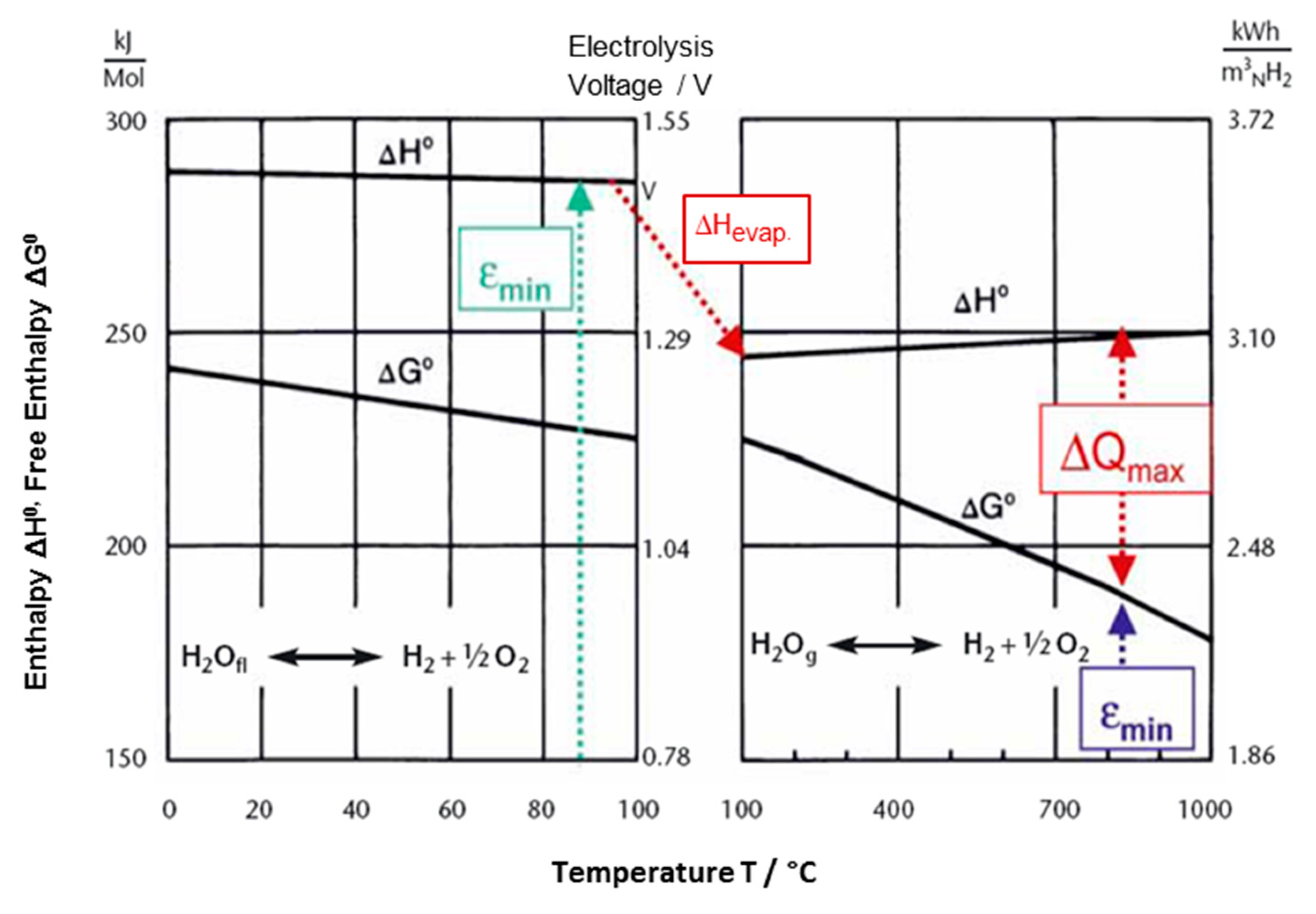
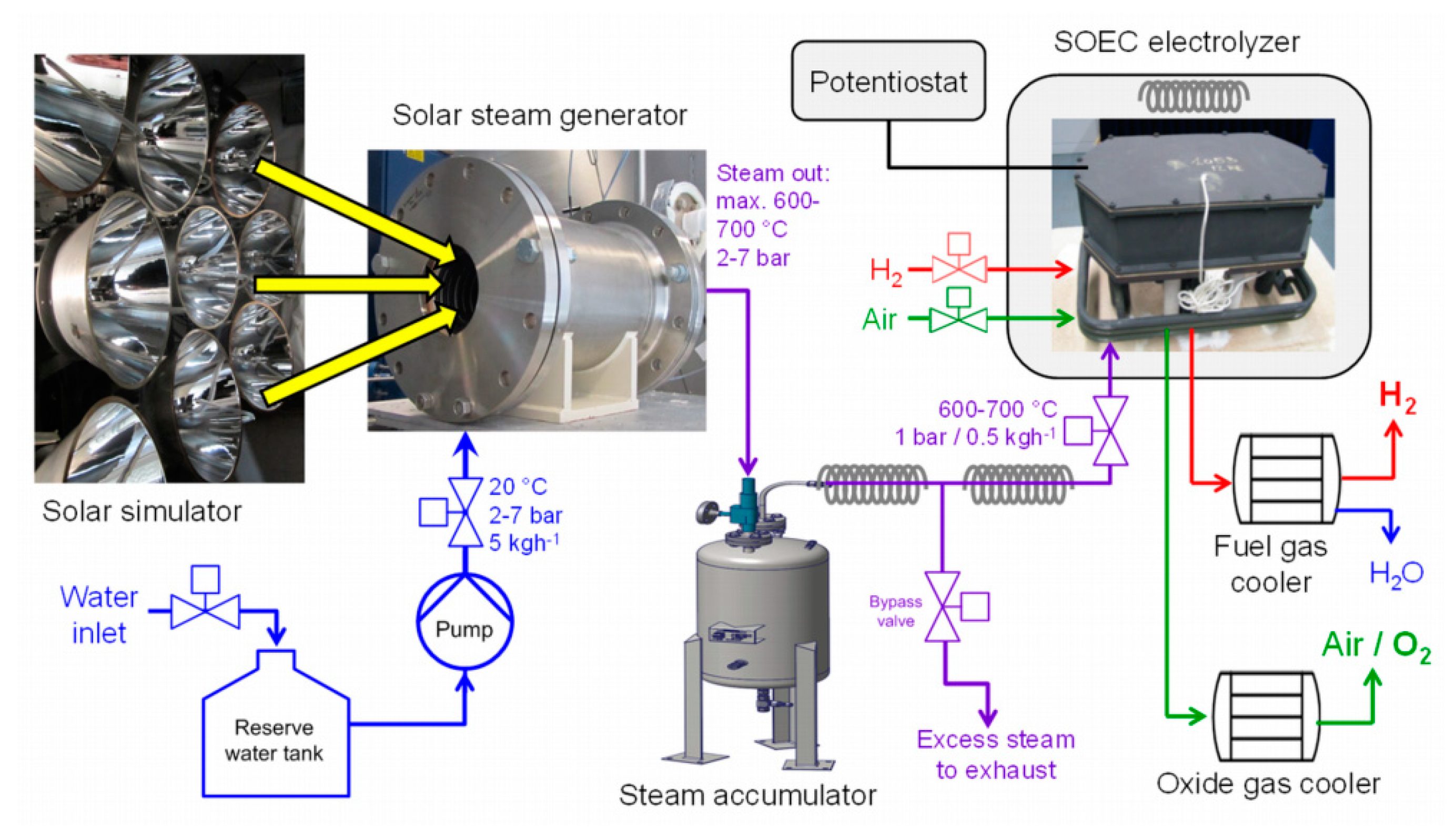
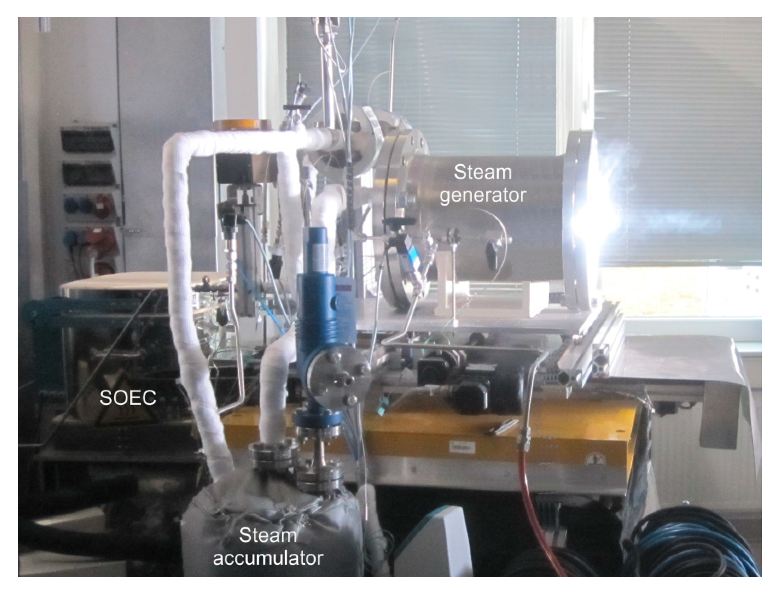
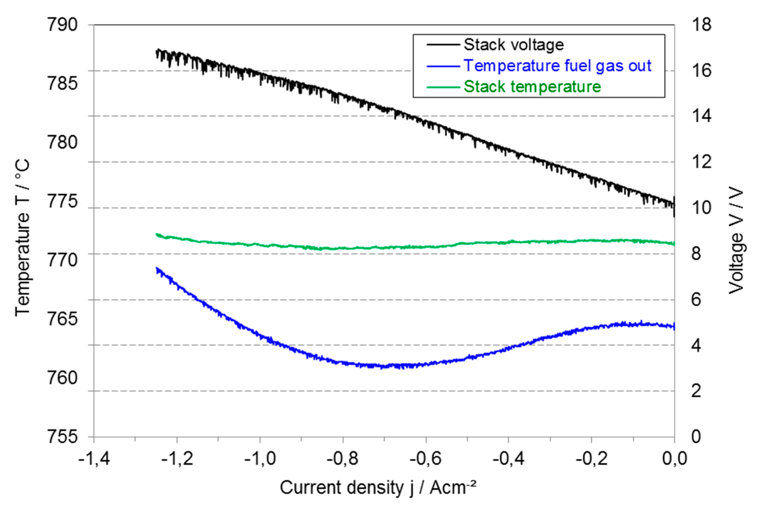
3.2. High-Temperature Steam Electrolysis with Integration of Solar Heat

Water electrolysis is considered the best suited technology for the production of fossil-free (“green”) hydrogen which is needed for the storage of large amounts of renewable energy. The highest electrical efficiency among the existing water electrolysis technologies is shown by solid oxide steam electrolysis (SOE). Compared to low-temperature electrolysis techniques such as alkaline electrolysis and proton exchange membrane electrolysis, the significantly higher operating temperature of SOE results in faster reaction kinetics and higher energy efficiency. The electric energy demand can be even further reduced when part of the required energy for the endothermic water splitting reaction is provided by high temperature heat from solar thermal power.

3.2.1. Approach and Assumptions

As shown in Figure 5 the enthalpy of water ΔH0 and hence the required minimum energy for water splitting is reduced considerably at the phase transition from liquid water to steam. The Gibbs free enthalpy ΔG0 for water splitting continuously decreases with increasing temperature, whereas the enthalpy ΔH0 remains almost constant. This implies that the thermodynamic cell voltage for steam electrolysis is lower than that for electrolysis of liquid water. Thus, steam electrolysis consumes less electrical energy compared to low-temperature electrolysis processes. Moreover, at high temperatures part of the required energy for water splitting can be provided by heat from external sources. The maximum amount of heat ΔQmax to be integrated into the electrolysis process is given by the difference between the enthalpy of water splitting ΔH0 and the Gibbs free enthalpy ΔG0, thus reducing the necessary electrical energy εmin [6].
Figure 6 schematically shows the experimental setup of the prototype system and Figure 7 the setup of the system in operation. Superheated steam generated solar thermally by using a high flux solar simulator with xenon short-arc lamps and a solar steam generator was used in a commercial electrolyser stack which was supplied by SolidPower (Mezzolombardo, Italy) containing so-called fuel electrode supported cells with an active area of 80 cm². For stack operation, a mixture of 1.4 slpm (standard litres per minute) of H2 and 12.0 slpm of steam with a composition of 90% H2O/10% H2 was supplied. To prevent the Ni + YSZ fuel electrodes of the cells from undesired oxidation to NiO + YSZ (Nickel (Ni)/nickel oxide (NiO) and yttria stabilized zirconia (YSZ)) 10% hydrogen was added as protection gas. By means of a high-temperature steam storage device, short-term interruption of irradiation which may occur during cloud passages can be bridged.

3.2.2. Results

To our knowledge, the experimental integration of solar heat into a commercial high-temperature steam electrolyser was successfully realized with this experiment for the first time [6]. By applying an appropriate control process, a continuous hot steam flow without major fluctuations was provided to enter the electrolyser stack. The system could be operated properly when the operating parameters of the different system components (water supply, gas volume flows, pressure, and temperature) were optimized. The SOEC stack was heated up to the operating temperature of 770 °C with hot steam gas from the steam accumulator and additional peripheral furnace heating during the start-up of the system. Figure 8 shows exemplarily a current-voltage curve as well as temperature data of the electrolyser stack at 770 °C operating temperature and a steam flow of 12.0 slpm (or 0.58 kg/h).
The stack showed an open circuit voltage (OCV) of 10.3 V when operated with a gas composition of 90% H2O + 10% H2 and the stack voltage increased almost linearly with increasing current density. This behaviour is well-known for SOEC due to the low activation polarization resistances of the fuel and air electrodes. Moreover, electrochemical impedance spectra showed relatively constant polarization resistances when current density was increased. Due to remaining steam mass flow instabilities from the steam generator, small voltage fluctuations in the jV-curve are still observed. The electrolysis voltage was approximately 16.5 V at a maximum current density of −1.25 Acm−2 resulting in a power of −1.65 kW for the electrolyser. An electrical stack efficiency of 93% based on the lower heating value of H2 and a steam conversion rate of 70% was calculated at this operation point with a production of 8.4 slpm of hydrogen. Due to the endothermic water splitting reaction, the stack temperature and the outlet temperature of the fuel gas first decreased with increasing current density reaching a minimum at a current density of −0.7 Acm−2. Afterwards the temperature increased again and the thermo-neutral point (TNP) was reached at about −1.0 Acm−2. At this operating point, the measured electrolysis voltage per RU was 1.32 V, which is close to the theoretical value of 1.285 V. At higher current densities than the TNP, the stack operation turns into the exothermal mode with further increase of the stack and gas temperatures.

3.3. Reverse Power Generation

In addition to the use of hydrogen as energy storage for on-demand power generation, liquid fuels can be an option because their storage and transportation does not require large infrastructure investments. Furthermore, their suitability for storage and secure handling makes them a practical solution for large energy storage applications. Already today, stationary gas turbines can be operated with liquid fuels like diesel or heating oil. However, the production costs of refined synthetic fuels are high, and therefore a sensitive parameter for their implementation. On the other hand, gas turbines have a high fuel flexibility, which leads to questions of what boundary conditions are required for the gas turbine combustion and whether there is a product or an intermediate from the production of synthetic fuels that could be used in a gas turbine as liquid energy source. This work focuses on the development of a fuel flexible gas turbine combustor for typical liquid intermediate products from the Fischer–Tropsch synthesis process and to demonstrate the feasibility in a micro gas turbine application.

3.3.1. Approach and Assumptions

The liquid phase directly after the phase separation step was selected as a representative for an intermediate from the Fischer–Tropsch process. In Figure 1, the extraction is located between the synthesis step and the product upgrading and refining step [27]. Based on this fuel, the combustion relevant parameters like ignition delay time and laminar flame speed were measured using shock tube experiments and a laminar conical burner experiment [28,29]. Emission behaviour was evaluated using a high-temperature flow reactor [30,31] in combination with mass spectrometry. Based on this, a data reaction model was developed [32] and generic combustion experiments with the fuel were carried out to validate the atomization and evaporation models of the computational fluid dynamic (CFD) simulation. In a next step, these validated tools will be used to design a combustion chamber specifically optimized for this kind of fuels. Swirl combustors typically used in gas turbine applications have only limited fuel flexibility and are sensitive to changes in the combustion behaviour of the fuel, unlike the jet stabilized combustion systems which have an advantage because of their high momentum jets and their good mixing behaviour. On the other hand, this type of burner, which has proven to have a very high fuel flexibility for gaseous fuels, has a higher dependency on the fuel spray quality, which depends on the physical properties of the fuel. To take advantage of jet-stabilized combustion, the combustor system developed in this project will be based on a jet stabilized design. After designing the burner with the CFD tools, preliminary atmospheric tests were carried out in the laboratory to prove the functionality of the combustion system. Finally, it is planned to test the combustion chamber in a 100 kWel micro gas turbine demonstrator.

3.3.2. Results

The liquid phase, which was selected as a representative of an early stage fuel, was characterized using a GC × GC analysis. The detailed fuel composition is shown in Figure 9. It consists of 85.6 wt% n-alkanes and 1.3 wt% iso-alkanes, followed by 13.1 wt% of alkenes. While the alkene distribution has its peak at a carbon number of 9, the alkane distribution has its peak at a carbon number of 13. About 25 wt% are larger than hexadecane. The high concentration of alkene molecules in the liquid phase is different compared to other synthetic fuels and can have an influence on the combustion behaviour of the fuel. The kinetic measurements, which will be carried out in a subsequent step, will reveal if the alkene concentration has a significant influence on the ignition delay time. On the other hand, the high number of higher hydrocarbons will affect the evaporation of the fuel droplets and can thereby influence the emission and sooting behaviour of the combustion. This will be investigated in a generic combustion experiment and can be compared to other synthetic fuels.

3.4. Discussion

The developed simulation model for the metal oxide thermochemical cycle can be used to rank perovskite redox materials according to the expected energy consumption in a two-step thermochemical cycle. The model considers the thermal energy required to drive the chemical reaction, the sensible energy stored in the redox materials at high temperature, and the energy necessary to maintain a low oxygen partial pressure during reduction through pumping, as well as the energy necessary to generate steam. Moreover, it is possible to predict the amount of hydrogen or carbon monoxide generated as the thermodynamic data allow for the calculation of the change in non-stoichiometry under different redox conditions.
The proof-of-concept of integrating solar energy for evaporation and superheating of water to be used as steam in SOE has been demonstrated, but the efficiency of the total system must be optimized with great potential in terms of high-temperature steam storage and increased stack performance. DLR will develop a concept for suitable heat storage at the highest possible storage temperature in order to ensure a reliable steam supply even over longer periods of time when the sunlight is not sufficiently intense. This system optimization makes it possible to carry out the following experiments with a higher heat input through solar radiation, and thus significantly increase the overall efficiency of the system. High temperature electrolysis allows to not only split molecules of water steam but also of carbon dioxide or a mixture of both to produce synthesis gas, a mixture of H2 and CO. By applying a co-electrolysis process of H2O and CO2, synthesis gas can be produced, which can then be processed in a down-stream catalytic process step into various hydrocarbons to be used as synthetic fuels such as methanol, methane, gasoline, or diesel. The integration of solar heat is intended to be further developed and also used for the co-electrolysis process for syngas production.
The intermediate product from the Fischer–Tropsch process differs significantly from typical synthetic fuels regarding its chemical composition. In particular, the high number of unsaturated hydrocarbons can influence the combustion behaviour. In another step, this influence will be investigated by measuring the combustion properties of the fuel. Based on the results, a combustion system will be designed for this fuel and reverse power generation will be demonstrated.

4. Designer Fuels for Aviation

Aviation turbine fuel is a liquid mixture of hydrocarbon molecules ranging from 9 to 16 carbon atoms. It has been developed over the last 70 years, now meets very stringent safety and performance requirements, and can withstand a wide range of operational conditions. Conventional aviation turbine fuel is made by refining and blending fossil crude oil, which makes aviation a direct contributor to anthropogenic climate forcing. The climate impact of aviation is quantified in terms of its “radiative forcing of climate” [33]. This metric is based on experiments which have displayed a direct proportionality between a change in global mean radiative forcing (RF) and a change in global mean surface temperature. From a life cycle analysis (LCA) perspective, the CO2 emissions directly related to the use of fossil energy, in any sector, results in a positive RF: warming. However, the specificity of aviation is that out of the total estimated RF of 0.078 Wm−2 [33], which represents 4.9% of total forcing from human activities, non-CO2 effects are the dominant part. In fact, the direct CO2 emissions from an LCA perspective account for about 40% of the total aviation-related climate warming. The major aviation related contribution to anthropogenic climate warming comes from aviation-induced cloudiness [34]. At cold and humid ambient conditions at cruise levels, aircraft soot emissions lead to contrail formation in the exhaust plumes of aircraft engines, and further to persistent contrail cirrus [35,36]. These ice clouds reflect solar radiation and absorb and re-emit terrestrial radiation, which, in sum, increase the energy budget of the atmosphere and thus lead to a positive radiative forcing or warming of the atmosphere [37]. Overall, the climate impact of aviation is related to its emissions. Electrification is one mitigation option for certain ground transportation vehicles. In commercial aviation, mid- to long-distance flights rely on gas turbines for at least one aircraft development and life cycle (40 years), since the specific energy content of aviation fuels is almost two orders of magnitude higher than current batteries, and no such technology is available today. Sustainable Aviation Fuels (SAF) have the significant potential to reduce both CO2 and non-CO2 impact on climate change. While blending standard Jet-A1 jet fuel with a biofuel leads to reduction in soot particle emissions as demonstrated in ground tests [38] and in-flight experiments at cruise altitudes [39], the experimental quantification of the resulting effect on contrail cirrus was missing. In addition, one question to be answered is how the impact of SAF can be maximized. Fuel design is a promising answer for the near future.

4.1. Design Criteria and Concept for Alternative Aviation Fuels

The design of alternative aviation fuels must follow various criteria determined by technical feasibility and sustainability, as well as optimization targets in terms of performance and emissions reduction. The project focuses on both restrictions and potential benefits that need to be analysed and defined.

4.1.1. Approach and Assumptions

The first and most important criterion for defining the design space is safety. To ensure safe flight operations around the globe with modern, as well as legacy aircraft and engines, aviation turbine fuel has to meet the regulatory specification requirements defined in international standards or in similar national adoptions of these specifications at every airport. In the aviation industry, the two major jet fuel specifications are the Defense Standard 91-91 [40] for Jet A-1, and the ASTM D1655 [41], for Jet A. The fuel standard specifications do not explicitly determine the fuel formulation. Instead, they define minimum requirements in terms of safety, performance, material compatibility and handling. In 2009, based on the pioneering certification process that the Sasol Semi-Synthetic Jet Fuel had been through, the standard was modified to include approval procedures of new aviation turbine fuels: ASTM D4054-09 “Standard Practice for Qualification and Approval of New Aviation Turbine Fuels and Fuel Additives”. During this qualification process, more than 70 different properties were tested to assess the basic fuel chemical/physical properties and the fuel performance in the aircraft engine, fuels system, and ground handling of the fuels. By this rigorous testing, the drop-in quality (i.e., the quality of the new synthetic fuels to be used as equal or improved replacement of conventional crude oil-based jet fuel) is ensured. If a fuel is successfully approved, it will be annexed to ASTM D7566, the standard specification for aviation turbine fuels containing synthesized hydrocarbons. In recent years, five pathways for the production of sustainable aviation fuels have been approved by ASTM and further adopted by the Defense Standard and other national regulatory bodies. These alternative aviation fuels have to be blended with conventional aviation fuel from crude oil to fulfil the property constraints that ensure their drop-in capability as defined in ASTM D7566. The maximum blending ratio is up to 50% alternative fuel for Fischer–Tropsch synthesized paraffinic kerosene (FT-SPK), synthesized paraffinic kerosene from hydroprocessed esters and fatty acids (HEFA-SPK), alcohol-to-jet synthetic paraffinic kerosene (AtJ-SPK), Fischer–Tropsch SPK plus aromatics (SPK/A), and 10% max for synthesized iso-paraffins (SIP) from fermented sugars. The approval process tests fuel physical and chemical properties, as well as complex sub-processes occurring in the aircraft and engine fuel and combustion systems. The multi-variable space of acceptable thermophysical properties and sub-processes then defines a multidimensional space of possible chemical families and species, in which one can design future aviation alternative fuels.
Although not at the core of the present work, it is noteworthy to underline the fact that not every alternative fuel contributes to reducing the CO2 emissions from an LCA perspective. Directly (e.g., use of fossil feedstock such as coal or natural gas) or indirectly (e.g., indirect land use change ILUC), the production of alternative fuel can be counterproductive in terms of renewability and more generally with respect to sustainability criteria. Therefore, although outside the realm of technical feasibility, as sustainability is essential to selecting the proper feedstock and process technology, we rely on auditing organizations which follow internationally and multi-stakeholder-agreed sustainability criteria (e.g., Directive (EU) 2018/2001 [42]) for this assessment. If the alternative turbine fuel is produced from a renewable feedstock and meets other sustainability criteria, in particular with respect to land use change and avoiding competition with food and animal feed (see [42]), it then qualifies as sustainable alternative jet fuel (SAJF).
Now that the technical design space has been defined, as well as the pool of available and approved molecules, and the criteria for selecting which pathway to take towards manufacturing these molecules, target properties and performance criteria can be introduced to further refine the design space and proceed with the actual fuel design.

4.1.2. Results

The design targets selected here are relevant to any fuel: the method and tools in the framework of the proof of concept underlined hereafter are thus applicable to future fuels across all sectors. In the particular case of aviation turbine fuels, energy content is crucial (since fuel efficiency is directly related to CO2 emissions and pollutant emissions reduction) so the objective was to maximize the net heat of combustion and minimize soot emissions.
From quality control applied systematically to each batch of conventional Jet A-1 coming out of a refinery with the mandatory documents (e.g., certificate of analysis CoA) all the way to the characterization of new molecules as potential alternative fuel candidates (see approval process ASTM D4054), chemical analytics play a crucial role. In particular, determining the detailed chemical composition of the fuel candidate is key in assessing the technical feasibility. A method based on chromatography (1D or 2D) coupled to mass spectrometry is becoming very valuable in deriving a detailed quantitative composition. To illustrate that aspect, Figure 10 shows the composition of a typical crude oil-based Jet A-1, which contains several hundreds of components that can be grouped into different chemical families and chain length per family. In addition, this can be compared to a specific SAF, here HEFA-SPK, displayed in Figure 11. Although these are specific examples, they can be generalized. In fact, the composition of HEFA-SPK is close to the one of Jet A-1 in terms of the range of carbon number, which obviously lies within the kerosene fraction. The main differences lie in the fact that there are fewer families. HEFA consists mainly of alkanes (paraffins) with a majority of iso-alkanes and with no aromatics and thus has fewer species. Moreover, the shape of the HEFA-SPK species distribution departs substantially from the classical crude oil-based fuels.
Then, the next step consists of binding the design space to yield a drop-in fuel, which lies within the specification requirements. With the example of density, one can see in Figure 12 that blending 49 vol% of HEFA-SPK (see green symbol which lies within ASTM D7566 HEFA-SPK specifications) together with 51 vol% of fossil-based Jet A-1 (see red symbol which lies within the ASTM D1655 conventional Jet A-1 specifications) brings the resulting SAJF blend (see yellow symbol) into the Jet A-1 range, which is the target. A similar design space restriction applies to other properties, e.g., aromatics content or viscosity. For the potential drop-in fuel, as can be seen in Figure 13, both blending components are in the specification range.
Next, to understand the potential, the net heat of combustion of a specific crude-oil based Jet A-1 selected as reference was plotted against alternative jet fuel blends in Figure 14. The standard method ASTM D4809 was used for determining the net heat of combustion of all Jet A-1 fuels in the data base and ASTM D3338 for the blends and pure SAJF. The soot reduction potential displayed in Figure 15 was calculated based on a qualitative correlation between black carbon emissions and fuel hydrogen content. Both figures show a considerable improvement in the median values towards the optimization targets for the synthetic fuel blends. The distribution (min–max range) is due to variations in conventional and synthetic fuel composition and displays a part of the optimization potential that can be used when the relationship between fuel composition and performance is well captured and can be utilized.

4.2. Discussion

The design space was restricted to drop-in fuels; in other words, there was no modification of any sub-system or infrastructure necessary for direct use today. Blends with maximum 50% SAJF do yield substantial performance improvements and emissions reduction (see Figure 14 and Figure 15), but they will not enable commercial aviation to achieve the extremely challenging goals set by policy makers and industry, e.g., ATAG goal of 50% reduction in CO2 emissions compared to the year 2005 [44]. It is therefore anticipated that only near drop-in fuels (pure SAJF for example), when developed with proper fuel design methods, will maintain identical safety records while reducing CO2 emissions to the defined targets in the given timeframe.

5. Oxygenated Fuels for Road Transportation

In contrast to the energy, agriculture, or household sector, where significant GHG emission reductions have been achieved in Germany since 1990, the transportation sector has even slightly increased its GHG emissions [45]. The second environmental issue of road transportation is the emission of locally toxic pollutants such as nitrogen oxides (NOx) and particulate matter (PM). The negative impact on air quality has led to several bans on driving in numerous European cities.
The most prevalent measure is the electrification of road transportation. This shifts possible CO2 emissions to the energy sector and is only reasonable if renewable energies are used for power generation. Even in this case, electric mobility today still has a number of shortcomings regarding range, infrastructure or expensive vehicle purchase. On these grounds the share of electric vehicles in Germany (including plug-in hybrids) was still below 1% in 2018 [45] and a change of trend is not foreseeable. Climate-neutral future fuels overcome these issues and could be a quick and effective measure for CO2 reduction in road transportation since existing vehicle fleets and infrastructure could be used in a conventional manner. To tackle the problem of locally toxic pollutant emissions in the same course, oxygenated chemical components such as alcohols or ethers can be used as fuels. They are known to burn much cleaner, especially regarding PM emissions.
The work within Future Fuels includes fundamental combustion experiments and modelling in order to study its applicability and effects on vehicle emissions, and an extensive literature review regarding pollutant exhaust emissions. Another objective of the ongoing work is to address the question of user acceptance regarding new synthetic fuels.

5.1. Review of Combustion Characteristics and Pollutant Emissions Behaviour of (Blended) Oxygenated Fuels

The literature review focused on combustion characteristics of (blended) oxygenated fuels on the basis of engine bench tests to analyse the effects on gaseous pollutant emissions characteristics. In this article, we present the literature review of gaseous and particulate pollutant emissions of butanol as an alcoholic component, and oxygenated ethers (DMM/OMEn).

5.1.1. Approach and Assumptions

The first step was a screening for all possible oxygenated chemicals discussed as fuels in transportation. On this basis, the most promising candidates were selected, namely:
  • Methanol
  • Ethanol
  • Butanol (n- or i-)
  • Dimethoxymethane (DMM)
  • Oxymethyleneethers (OME) 3–5
Several studies have been reviewed which investigate combustion characteristics of (blended) oxygenated fuels mostly on the basis of engine bench tests and analysis of the effects on gaseous and particulate pollutant emissions behaviour. As the reviewed studies differ in test, engine, and vehicle conditions, the relative deviation of the emission values from the oxygenated fuel blend in comparison with the respective emission value of the reference fuel was calculated. Thus, the results of all the reviewed studies become comparable and the emission characteristics of oxygenated fuel combustion can be further analysed. With this approach, emission trends and suitable oxygenated fuel blending rates can be identified.

5.1.2. Results

In this paper, we focus only on the results for n-butanol and leave the other oxygenated components to future publications. This does not mean any prioritization, since the processing and final comparison of the entire results is not finished yet. The trends of hydrocarbons (HC), CO, NOx and particulate emissions (PM/PN) for butanol-gasoline blends were analysed for use in spark ignition engines (Figure 16). The butanol-gasoline blend emission values were calculated as the percentage deviation from neat gasoline as the reference fuel as a function of butanol blending rate. The CO, HC and NOx emission deviation values correspond to the stoichiometric operating condition—as this is the operating point of spark ignition engines. The particulate emission deviation values are averages extracted from the respective studies. The same pollutants are further discussed regarding the blending of DMM and OMEn as oxygenated ethers with diesel fuel.
As CO emissions are mainly influenced by the air-fuel equivalence ratio (λ) [46], no clear trend on CO emissions can be observed by blending butanol to gasoline (see Figure 16). The main fuel characteristics of butanol influencing an increase of CO emissions due to decreasing combustion temperature are the smaller lower heating value (LHV), as well as the higher latent heat of vaporization of butanol against gasoline. Furthermore, a shorter major combustion duration and decreases in both CO post-flame oxidation and engine power output were observed, resulting in increased specific CO values with butanol(-gasoline) combustion [47,48]. On the other hand, better combustion quality from blending butanol to gasoline as the alcohol contains oxygen which supports the CO oxidation to CO2 is reported by [49].
HC emissions can be considered as an indicator of the combustion quality [47,50]. HC emissions are reduced for butanol blending rates up to 40% (Figure 16) because of the oxygen content of butanol which improves the combustion process [47]. For higher butanol blending rates, an increasing trend of HC emissions is observed [50] with more than 2.5 times higher HC emissions for neat n-butanol compared to gasoline [46,48]. The increase of HC emission for butanol blending rates >40% is associated with the lower stoichiometric air-fuel ratio of n-butanol compared to gasoline. This means that more fuel needs to be injected [47]. Combined with the high latent heat of vaporization that decreases the combustion temperature, this can lead to more unburnt fuel [48].
Investigations of CO and HC emissions characteristics of DMM/OMEn blends with diesel fuel have shown that emission trends are also linked to engine load. At low loads, CO emissions are in general low, as there is enough oxygen available for CO to oxidize to CO2 so that fuel properties have a low impact [51]. However, for high loads and high exhaust gas recirculation (EGR) rates, a 15% or 25% OME3–6 blend can reduce CO significantly by its high oxygen content as well as its high volatility. Even if HC emissions are also significantly reduced, this pollutant is primarily influenced by the load and thus the temperature. Omari et al. [52] observed increasing CO emissions with raising DMM blending rates at a low load point while for all higher load points, CO and HC emissions decrease with increasing blending rates due to the low cetane number (CN) of DMM. Concerning lower DMM/OMEn blending rates, studies have shown that CO and HC emissions do not deviate much from diesel fuel values [53,54]. However, for the neat OME3-5, they observed increased CO and HC emission. Presumably, a higher density of OME leads to an excessive injection angle which can cause several phenomena of incomplete combustion. Another reason may be the lower exhaust gas temperature than diesel fuel, which is caused by the lower LHV of OME that reduces the efficiency of the diesel oxidation catalyst (DOC) [53].
NOx emissions mainly depend on the combustion temperature and on the excess oxygen available in the exhaust gas [46]. Butanol contains oxygen, by which a more complete combustion, higher combustion temperatures, and thus higher NOx formation result. Butanol, however, also reveals a combustion-temperature decreasing effect which reduces the formation of NOx. With a higher butanol blending rate, the temperature decreasing effect overcompensates the temperature increasing effect, which results in the increment of HC emissions as well as in the decrease of NOx emissions (Figure 16). This can also be shown for n-Butanol-gasoline blends used in a Homogeneous Charge Compression Ignition (HCCI) engine, where the lower LHV of n-Butanol reduces the indicated mean effective pressure (IMEP), the combustion temperature and NOx emissions [55].
Furthermore, NOx emissions can be reduced by blending DMM/OMEn with diesel fuel independent of the blending rate. The reasons for the decrease of NOx emissions mentioned in the literature are the reduced mean bulk temperatures reached with oxygenated fuels [54] and for low and medium loads, the lower CN and lower LHV of the blends resulting in lower heat release rates [51]. The authors also emphasized that NOx emissions are mostly dominated by the exhaust gas recirculation (EGR) rate, while fuel properties become more relevant at low EGR rates. Nevertheless, several studies showed higher raw NOx emissions from DMM-/OMEn- diesel blend combustion regardless of the level of the blending rate [52,53,56]. The reasons for this are the longer phases of higher temperatures and locally increased λ values with OMEn combustion, higher flame temperatures, and the lower LHV of OMEn (blends), leading to a higher oxygen concentration in the exhaust gas compared to diesel fuel. The latter yields a decrease of exhaust gas temperature, which reduces efficiency of the selective catalytic reduction (SCR) catalyst and, thereby, the NOx increase at the tailpipe is even higher [57].
Figure 16. Deviation of gaseous and particulate pollutant emissions from butanol-gasoline blend combustion from those of neat gasoline fuel combustion depending on the butanol blending rate. Data derived from: Wigg et al., 2011 refers to [46], Li et al., 2017 refers to [47], Nithyanandan et al., 2016 refers to [48], Dernotte et al., 2010 refers to [50], He et al., 2013 refers to [55], Liu et al., 2019 refers to [58], Vojtisek-Lom et al., 2015 refers to [59], Hergueta et al., 2017 refers to [60], and Vojtisek-Lom et al., 2013 refers to [61].
Energies 13 00138 g016
Oxygenated fuels reveal a high particulate emission reduction potential through the oxygen content in the fuel molecular structure. In the case of a 20% n-butanol-gasoline blend, Liu et al. [58] obtained PM reductions between 9% and 24% and particulate number (PN) reductions of approx. 53% within their conducted NEDC tests on the dynamometer using a gasoline direct injection (GDI) vehicle. Vojtisek-Lom et al. [59] determined PM emission reductions for a n-Butanol blending rate of 25% especially for urban and rural driving conditions, while the decrease of PN emission also happens for the motorway part. Hergueta et al. [60] concluded that the oxygen content of butanol can decrease the soot formation rate as well as optimize the oxidation rates of the already formed particles. This is especially shown for blending rates up to 33%, reaching PM/PN emission reductions of >50%; however, Vojtisek-Lom et al. [61] obtained approx. 30% higher PM emissions considering an 85% n-butanol blend (cf. Figure 16).
The baseline of the PM emission reduction relating to DMM/OMEn is also their high oxygen content and further, the lack of C–C compounds, which increases the soot oxidation rate [52,53]. Similarly to butanol, these fuels show an increase of PM/PN reduction with increasing blending rates, but as a difference, they yield the highest emission reductions as neat fuels (see [56,57,62]). There are, however, some exceptions that need to be mentioned. Several studies showed significant soot and therefore PM emission reduction for small DMM/OMEn blending rates at low load points. However, when loads are increased, PM reductions decrease or become zero [56,57]. Furthermore, studies showing PM reductions for smaller OMEn blending rates stated that PN emissions can still rise above diesel fuel levels, assuming that fine particles which originate from diesel fuel are responsible for this. Neat OME shows extreme high PM and PN reductions independently of the operating point [56].

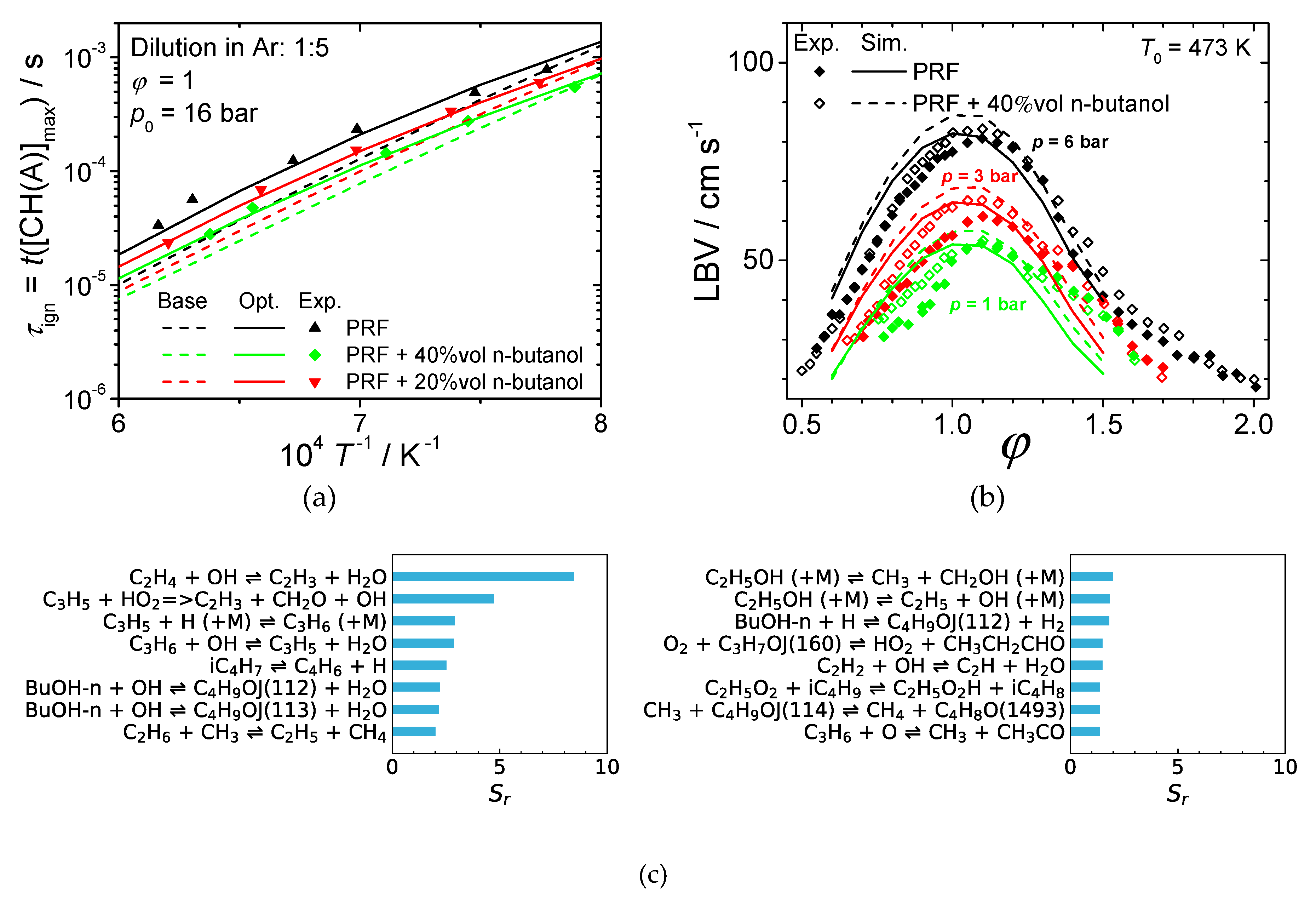
5.2. Combustion Experiments and Modelling of (Blended) Oxygenated Fuels

In order to evaluate the application potential of new fuels, combustion characteristics and pollutant emission tendencies need to be investigated. As a first step in the analysis, fundamental experiments and chemical kinetic modelling were performed. Specifically, ignition delay times (IDT) were measured in a shock tube for various conditions and laminar burning velocities (LBV) were determined with a Bunsen-type burner for elevated pressures. These data give important information on the ignition behaviour and the heat release of fuels. Furthermore, the data were utilized to validate the chemical kinetic model. Subsequently, the validated chemical kinetic model provides more details on pollutant formation and destruction in the reaction zones, and therefore enables the numerical evaluation of pollution emission tendencies in combustion applications.

5.2.1. Approach and Assumptions

As the first promising fuel candidate, n-butanol was selected and investigated. Thereby, the combustion characteristics were investigated for mixtures of n-butanol and a gasoline primary reference fuel (PRF), consisting of 90 vol% iso-octane and 10 vol% n-heptane. The IDTs were measured with a shock tube at different pressures and initial temperatures [63]. The IDTs were determined at 1 bar, 4 bar and 16 bar. The diluent for the fuel oxygen mixture was Argon. To define the IDT the maximum concentration of the chemiluminescence signal of the excited CH(A), radical was selected, which was measured at the end wall of the shock tube. More details on the experimental facility and setup can be found elsewhere [63].
The LBVs of n-butanol PRF mixtures in air were measured with the cone angle method at pressures of 1 bar, 3 bar, and 6 bar [63]. For this experimental set, the preheat temperature of the unburnt gas mixture was set to 473 K. In-depth details on the experimental setup and methods for this measurement can be found in [63].
For the development of an initial base chemical kinetic model for the combustion of the n-butanol PRF mixtures, the automated approach of the Reaction Mechanism Generator (RMG) [48] was selected in a previous study [64]. The initial automatically generated chemical kinetic model consists of 181 species and 4567 reactions. Since the RMG method included all possible isomers of the different species—for which many are not impacting the combustion characteristics—a reduction of the model was performed. This was done by applying the rapid reduction method of the linear transformation model (linTM) [65]. As a result, the model was reduced to 133 species and 1200 reactions [63], allowing computationally more efficient subsequent numerical investigations. In this study, the reduced model was optimized on the ignition delay times to increase the model prediction abilities. The optimization was performed on basis of the methods of the linTM [65]. For selection of the active reactions in the optimization, a global sensitivity analysis of the ignition delay times on basis of the linTM was performed. After the evaluation of this analysis, 16 reactions were selected. These 16 reactions and their global sensitivities coefficients Sr are shown in Figure 15c. Most of these reactions are exclusively sensitive for the butanol system or very limited experimental or numerical data on uncertainty quantifications are available. The rate coefficients k were optimized within relatively small limits of Δlg(k) = 0.2.

5.2.2. Results

The experimental and numerical results of the IDTs and LBVs are illustrated in Figure 17. With the optimization of the chemical kinetic model, the experimental and numerical ignition delay times are in excellent agreement. With the addition of n-butanol to the PRF, the ignition delay times became lower. Moreover, the modelling results of the LBVs are in good agreement with the experimental data. Both the experimental and numerical results show the same trends of increasing flame speeds with the addition of n-butanol to the PRF. Both IDT and LBV indicate higher reactivity of PRF when adding n-butanol to the fuel. The higher reactivity leads to more complete combustion and this therefore causes less emissions of unburnt HC and CO. This agrees very well with the results of literature study in Section 5.1. Only at very high mixing percentages values from the study indicate higher HC and CO in the exhaust, but these results might have been caused by the design of the piston engines that were optimized for the combustion of gasoline. Thus, piston engines that are optimized for the different fuel mixture could lead to significantly reduced pollutant emissions when adding n-butanol to gasoline.

5.3. Discussion

In conclusion, the literature review shows that a butanol blending rate of 20% to 40% to gasoline is likely to achieve CO, HC, NOx and particulate emission reduction (cf. Figure 16). While gaseous pollutant emissions in context with DMM/OMEn combustion are mainly influenced by engine- and vehicle-side effects, soot or PM emissions are generally decreased with an increasing oxygenated ether blending rate. The central advantage that derives from this is the solution of the PM-NOx tradeoff, so that the EGR rate can be increased and thus, NOx emissions reduce dramatically. The NOx emission mitigation potential increases with the growing DMM/OMEn blending rate. On the other hand, especially considering DMM, the more the blending rate is increased, the more the fuel properties diverge from those of diesel fuel. This means that increasingly engine- and vehicle-side modifications need to be made. Analysing the cost-benefit ratio, Omari et al. [52] suggest a 35% blend of DMM with diesel fuel as the optimal blending ratio achieving a high soot reduction of approx. 90% and a deterioration of LHV and CN of 15% and 10% respectively. For higher blends or even the use of neat OME fuel, higher chain lengths of n = 3–5 should be considered as these provide fuel properties more similar to diesel fuel [66]. The largest remaining difference is the markedly lower LHV of OME fuel. How this will affect the combustion characteristics, as well as efficiency and emissions, is investigated in the ongoing work.
The experimental and numerical results of the combustion characteristics are in good agreement with the literature study. Butanol leads to a higher reactivity (decreased ignition delay times and increased flame speed) and to lower HC and CO emissions.
In addition, an investigation of user acceptance for the use of oxygenated drop-in fuels will be carried out on the basis of three discussion groups with vehicle fleet owners in commercial transport. The fleets include normal cars and commercial vehicles used for various services like facility management, construction work, medical services, and transport services in urban, regional, and long-distance applications. Based on various criteria such as type of vehicle, annual mileage, region of use, availability of synthetic fuels, and their effects on the vehicles (range, vehicle life, maintenance), and the attitude of drivers or vehicle owners towards environmental issues, a guideline for group discussions with test persons was drawn up. The next step was to implement and evaluate the group discussions. The result will be a description of user requirements and a discussion of the implications for the potential to reduce greenhouse gas emissions.

6. Advanced Propellants for Space Propulsion

Within this sub-project, three promising advanced green propellant systems are under investigation with regard to applicability and efficiency in rocket engines. Here, the DLR Institutes of Space Propulsion in Lampoldshausen, of Combustion Technology in Stuttgart, and of Structures and Design in Stuttgart are working together in a close collaboration. The work aims at different mission scenarios and tasks where performance, low costs, environmentally friendliness, and safe handling characteristics are essential. The objectives are to show and elaborate the potential of these propellant systems, to develop and to comprehend combustor processes and to mature the technology. Furthermore, focus is set on commercialization and usage and to provide the necessary knowledge to the industry.
The three selected promising propellant system candidates within this sub-project are the following:
  • The cryogenic bipropellant combination liquid methane/liquid oxygen (LCH4/LOX).
  • Liquid monopropellants consisting of hydrocarbons and nitrous oxide (HyNOx).
  • Green gelled propellants for rocket applications (GGeRA).
In the following section, an overview of the ongoing and planned work within this project and on the first obtained results is given. More detailed information about the work conducted within this subproject is presented in [67]. Lists of the relevant literature and surveys in relation to these green advanced rocket propellants or references to surveys are given in [67,68,69,70,71,72,73,74,75].

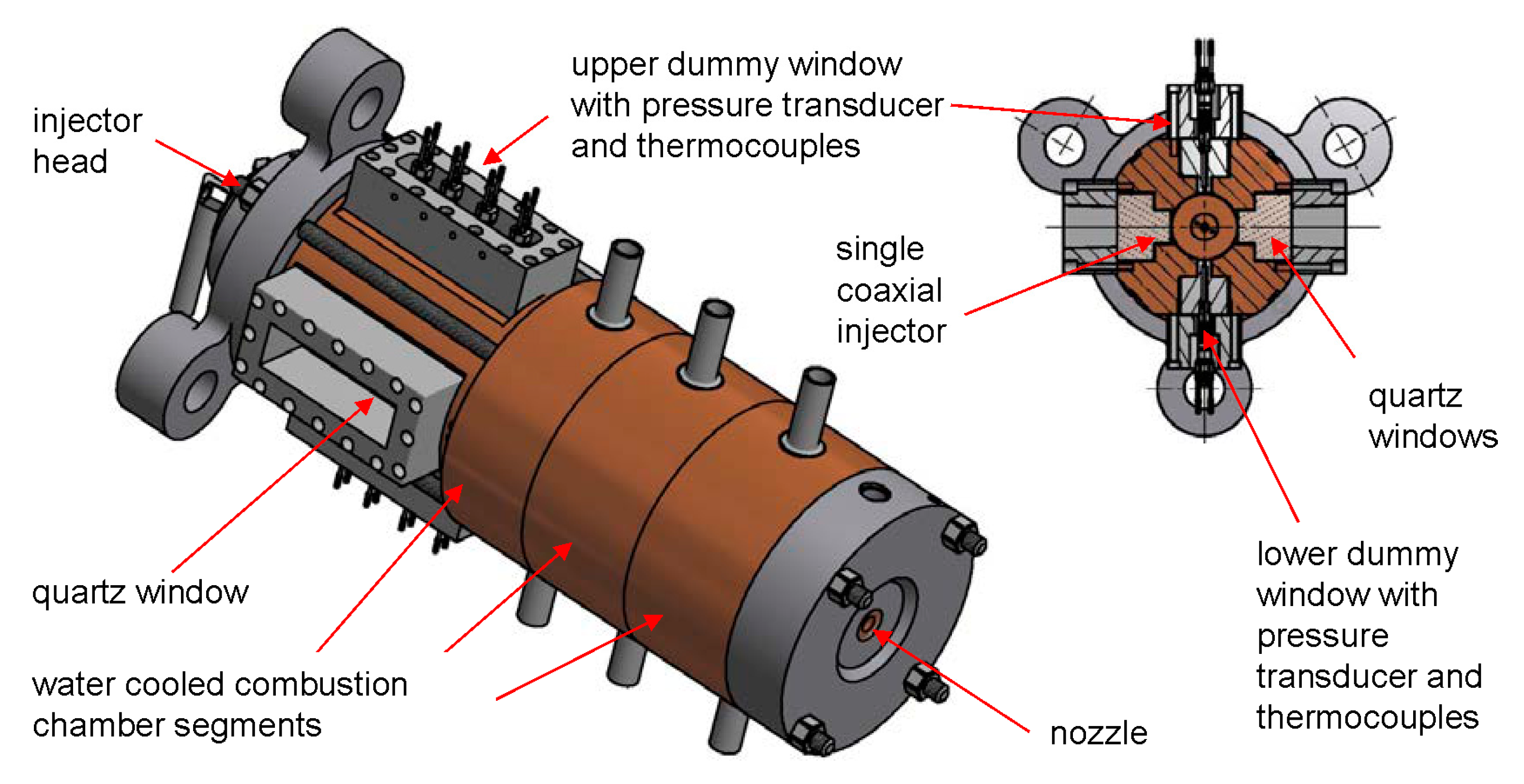
6.1. Cryogenic Bipropellant Combination LCH4/LOX

Recent analyses and developments have identified methane as a promising rocket fuel for launcher and in-space applications. There are a number of space missions for which methane has advantages over conventional rocket fuels such as hydrogen, kerosene, and the hydrazine derivative monomethyl hydrazine (MMH) within suitable fuel/oxidizer combinations.

6.1.1. Approach and Assumptions

The approach combines theoretical, numerical, and experimental work conducted at the DLR Institutes of Space Propulsion and of Combustion Technology. The experimental data obtained within the project will be used for the validation of a new methane kinetic mechanism for rocket engine conditions and the validation of a new computational fluid dynamic (CFD) model for the combustion of the liquid bipropellant combination LCH4/LOX. The validation data for the methane kinetic model are going to be obtained in a shock tube. The validation data for the CFD model will be obtained with hot-fire test runs of an instrumented sub-scale rocket combustion chamber with optical access, which can be seen in Figure 18.
The hot-fire tests require extensive preparatory work and careful planning because the workload of test facilities and the budget of the project do not allow repeated measurements. The numerical modelling also needs preparatory simulations which will be based on an existing methane turbulence combustion model. There are several combustion models which are used for modelling of methane combustion: chemical equilibrium flow, finite-rate chemistry (FRC), flamelet methods, and different eddy-dissipation models. The models not only have different validity regions but also require different computational resources. The simulations are formulated as an axisymmetric two-dimensional problem and are carried out using TAU (in-house DLR code) and ANSYS Fluent. The computational domain includes the combustion chamber, the short nozzle, and the end part of the injector. The inlet boundary conditions are mass flow rates; the outlet boundary conditions are supersonic; the walls are no slip.

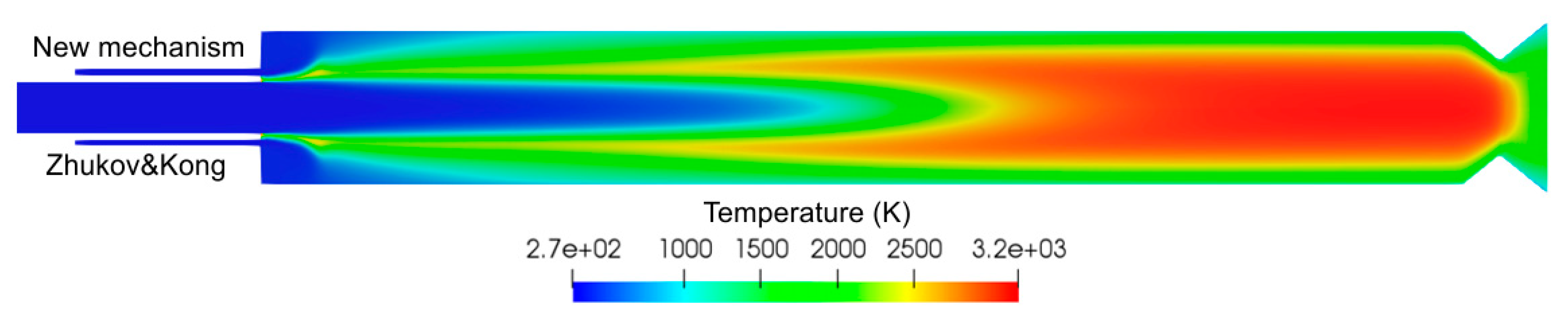
6.1.2. Results and Discussion

In Figure 19, the results of the preparatory simulations are shown. The goal of the current simulations is to prepare a numerical model for the validation test case and to find a good trade-off between the accuracy of the combustion model and the required computational resources.
The analysis of the results shows that when employing a flamelet method, the choice of the kinetic model for simulations virtually does not influence the simulation results. The current numerical model, which employs the flamelet combustion model, provides good results in the case of the gaseous bipropellant combination GCH4/GOX at low pressures. The validation of the developed numerical model for LCH4/LOX and high pressures is the task of the ongoing work.

6.2. Liquid Monopropellants Based on Hydrocarbons and Nitrous Oxide (HyNOx)

Hydrazine (N2H4) is currently the predominantly used storable monopropellant (only one single component, no oxidizer necessary) to power satellites, planetary probes and landers. Advantages of hydrazine are its sufficient specific impulse Isp (up to approx. 2300 m/s), long-term storability, easy decomposition via a catalyst and an explosion of the propellant is very unlikely [75]. Additionally, the derivatives of hydrazine monomethyl hydrazine (MMH) and unsymmetrical dimethyl hydrazine (UDMH) are used as hypergolic fuels, which react when getting in contact with distinct oxidizers like dinitrogen tetroxide (N2O4). They are typically used e.g., in re-ignitable rocket (upper) stages [76].
Unfortunately, hydrazine and its derivatives are highly toxic and carcinogenic. Thus, for handling, testing, and also for research, high-safety precautions are needed, which make handling and transportation of hydrazine complex and expensive. As a consequence of its high health risks, hydrazine was added to the candidate list of substances of very high concern (SVHC) in the frame of the REACH regulation of the European Community [77]. Thus, the use of hydrazine and subsequently of its derivatives could be restricted or even forbidden in the future, and this may have a significant impact on space applications and consequently the space industry itself.
Various alternatives for hydrazine are currently under investigation. A prospective low-cost and high-performance alternative is the mixtures of nitrous oxide (N2O) and fuels [69,78,79,80]. Here nitrous oxide and a fuel, or a fuel combination, are stored pre-mixed as monopropellant. These mixtures offer a performance similar to bipropellants (Isp ≥ 2900 m/s) with only one tank and one feeding system required. In addition, self-pressurization of the propellant tank is possible due to the high vapour pressure of nitrous oxide. Furthermore, the propellants are non-toxic and consist of cheap constituents.

6.2.1. Approach and Assumptions

The two main challenges regarding N2O/fuel propellants are the high combustion temperature and the danger of a flame flashback from the combustor into the propellant tank. To handle the high combustion temperatures, a future thruster needs an active cooling system. To avoid flame flashback, suitable flashback arresters for the propulsion system have to be designed, tested, and qualified.
Mixtures consisting of N2O and C2H4 or C2H6 have been selected for detailed investigations in the Future Fuels project.
The overall aim is to design, develop and test a 22 N thruster which shall have a technology readiness level (TRL) of 4. A TRL 4 means that the model thruster is able to work under relevant conditions with regard to its future application, i.e., near-vacuum conditions as in space. Numerical simulations are used to analyse the flame propagation and flashback behaviour of the propellant, the experimental heat fluxes are derived to design a regenerative cooled combustion chamber, testing of flashback arresters help to assure a proper function during all operation modes, different ignition methods are investigated and the performance of the propellant is evaluated in an experimental combustion chamber. For the research and development tests on the way to TRL 4, a vacuum chamber is available at the M11 test complex [81,82] in Lampoldshausen.

6.2.2. Results and Discussion

Via extensive flame speed measurements and ignition delay time measurements in shock tubes, chemical kinetic reaction mechanisms for the N2O/C2H4 and the N2O/C2H6 mixtures were validated, optimised, and with respect to the N2O/C2H4 reactive system, a reduced mechanism was provided [83,84]. Furthermore, the chemical kinetic reaction mechanisms were used to calculate quenching diameters and critical Péclet numbers for quenching of the N2O/hydrocarbon flame.
The performance of a N2O/C2H4 and a N2O/C2H6 propellant was evaluated in combustion tests by using an experimental model rocket combustion chamber. Here the performance (c* and combustion efficiency ηc*) of the propellant depending on the mixture ratio, the characteristic chamber length (L*) and the chamber pressure was derived [85,86]. Furthermore, heat loads on the combustor were determined to generate a valid dataset for a future regenerative cooling system [70]. Figure 20 shows the resulting heat fluxes to the chamber walls depending on the mixture ratio for the combustion of a N2O/C2H4 propellant combination.
In addition to the rocket combustor tests, a specific ignition and flashback test setup was used to test porous materials and capillaries as flashback arresters [87,88]. Those experiments provided data to design suitable flame barriers for the experimental thruster and served as reference experiments for numerical simulations.
During the project, a N2O/C2H6 propellant will also be investigated in non-premixed state, i.e., in a conventional bipropellant system where fuel and oxidizer are stored in separate tanks. Furthermore, a detailed system study regarding the different classes of green propellants will be conducted. Thus, the operation range of different propellants and propulsion systems will be shown, and the best solution for a given mission or task can then be selected.

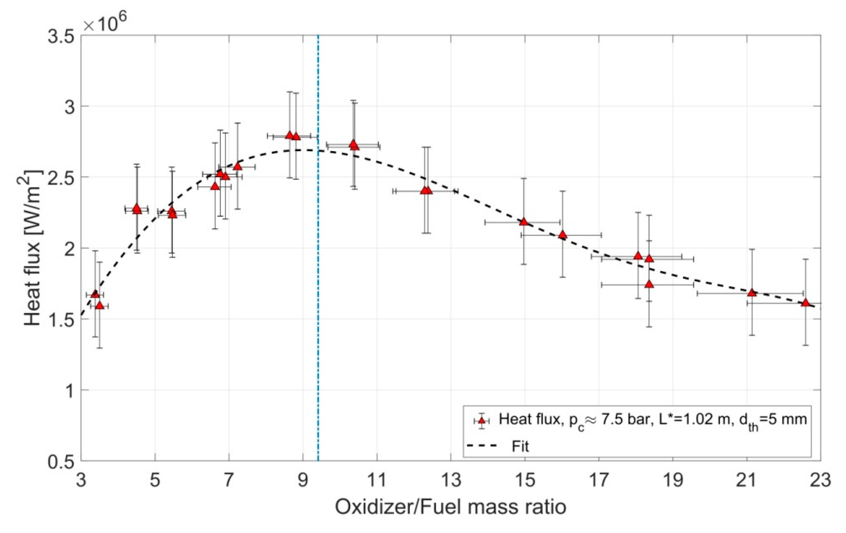
6.3. Green Gelled Propellants for Rocket Applications (GGeRA)

In general, gels are homogeneous mixtures of a base fluid and a thickener or gelling agent. The advantages of gel propulsion systems are the thrust throttling and control capability, easy handling, the possibility to tailor the propellant by addition of particles or energetic materials, and an improved operational safety [72,89,90]. At the DLR Institute of Space Propulsion in Lampoldshausen, basic research and technology development is performed on production, rheological properties, flow behaviour, spray characteristics and combustion performance of gelled propellants. In the context of the interdisciplinary project Future Fuels, novel hypergolic green gelled bipropellant combinations and associated technologies are investigated. In that regard, at the DLR Institute of Structures and Design in Stuttgart advanced cooling techniques and novel CMC-based combustion chamber designs suitable for gel rocket motors are studied.

6.3.1. Approach and Assumptions

The beneficial combination of controllable thrust and good storage characteristics offered by gelled propellants combine advantages of both liquid and solid propellant based rocket motors. This is enabled by the non-Newtonian flow properties of gels where thickeners and gelling agents are used to selectively modify the rheological behaviour of the base liquid (in the present a fuel and/or an oxidizer). A gelled propellant behaves like a solid at rest (see Figure 21), but shall otherwise be easily liquefied by sufficiently high shear stresses (shear-thinning fluid). For shear rates usually reached in injector systems, the flow characteristics of the gelled propellant typically become very similar to the ones of the base liquid itself, enabling an efficient atomization and combustion. More information on gel propellant properties, injection and rheology are given e.g., in [91,92].
Although a bipropellant system is more complex than a monopropellant system, it bears many advantages, including higher specific and density impulses, better safety characteristics, and non-reliance on an additional ignition system if the fuel/oxidizer combination is hypergolic. In order to identify possible fuels and oxidizers for a green, easy to handle, and storable hypergolic propellant system, a set of criteria based on GHS hazard sentences was created. A detailed description of the investigation was given by Kurilov et al. in [93].
The compatibility and durability of the chamber materials with the hot and reactive combustion gases of a bipropellant gel system must be verified. CMC-based combustion chambers have been successfully deployed for monopropellant gels in the past (see, e.g., [94]). Here, innovative combustion chamber designs including novel approaches for cooling, the application of new materials and manufacturing methods, e.g., ultra-high temperature ceramic matrix composites (UHTCMC) and additive layer manufacturing (ALM), and their performance under application relevant conditions are investigated.

6.3.2. Results and Discussion

To quickly test a large number of fuel/catalyst combinations, a simple drop test experiment was implemented. In this setup, the oxidizer—here, 98% high-test hydrogen peroxide (HTP)—was dropped from a specific height into a vial with fuel gel. By means of filming, the reaction with a high-speed video camera, the ignition delay times was determined. Figure 22 shows screenshots from a typical test run. With this setup, various combinations of methylated diamine gels and hypergolic catalysts were assessed [93]. As a result, Kurilov identified N,N,N′,N′-Tetramethylethylendiamine (TMEDA) hypergolically activated with copper-(II)-chloride as a very promising fast igniting fuel for combinations with HTP. Short ignition delay times (<15 ms) and a performance similar to commonly used highly toxic storable propellants seem actually feasible. Additionally, handling is easy and the potential fuel is available in high quantities at a fair (retail) price.
Since with the addition of only 1 wt% of catalyst the goal aspired to by Kurilov et al. [93] of an ignition delay time of less than 10 ms could not yet be achieved, further pre-tests are carried out both on the content and the type of catalyst. In parallel, a dedicated bipropellant model combustor setup was designed and manufactured. The first ignition and hot fire tests are planned near-term in order to verify the test results achieved in laboratory.

7. Conclusions and Outlook

The research work in the Future Fuels project is diverse and relates both to relevant aspects of production and to the very different challenges of use. The focal points are derived from DLR’s research areas, which are linked in numerous third-party funded projects with research work by strategic partners, for example, on synthesis processes or economic and ecological effects. The techno-economic analysis reveals that the expected costs of synthetic liquid fuels are approximately four times higher compared to fossil fuels. In addition, the bottom-up modelling showed that the PBtL concept can achieve a three-to-four-times higher fuel yield than is possible with pure biofuels. The modelling of the integration of synthesis processes into the power system shows the possibilities, but also the requirements regarding the flexibility of the future power supply. Here, the goal of further scenario analyses is to determine the interaction of the different infrastructures and the resulting expansion requirements in regional resolution in more detail.
The research work on the use of solar heat for the production of synthetic fuels so far shows basic feasibility. However, there are still major challenges for the efficient large-scale production of hydrogen and synthesis gas in the Earth’s sunbelt. Materials and technical concepts need to be further developed both for the realization of solar thermochemical cycles and for the integration of solar heat into high-temperature (co-)electrolysis.
Designing the composition of alternative sustainable jet fuels is a promising route to lowering the carbon dioxide footprint of fuel and to reducing engine emissions during the LTO cycle and at cruise conditions. Hence, this strategy helps to ameliorate airport air quality and to reduce aircraft effects on climate.
Oxygenated fuels for road transportation have a high potential to reduce particulate and gaseous emissions, depending on the blending rate and operating conditions of the engine or vehicle. The next step will be to complete the analysis at a well-to-wheel level and assess the environmental impacts of the production of oxygenated fuels and their usage in a passenger car via life cycle assessment.
Within the sub-project Advanced Rocket Propellants, three promising advanced green propellant systems are under investigation with regard to applicability and efficiency in rocket engines. The first results have been obtained since the project’s start in 2018 and are presented herein very briefly. The findings are promising and show that the candidates are indeed interesting for the application in future propulsion systems. Nevertheless, there are still important tasks to solve on the way to first applications.
The interdisciplinary approach of the project can be a blueprint for the further development of research and research collaborations in this field. The inter-thematic discussion and joint publication of the results is an essential element that helps to sharpen future research questions and to interpret and evaluate the work from different perspectives.

Author Contributions

Conceptualization: M.A., U.R., A.T., T.P., R.-U.D., G.S.; C.S., S.E., A.L., P.L.C., M.K., P.K., H.S., L.W., and H.K.C.; investigation: T.P., F.C., S.M., G.S.; N.M., M.F., T.M., B.R., M.S., L.W., F.L., V.P.Z., and C.K.; writing—original draft preparation: T.P., R.-U.D., G.S., S.M., N.M., S.E., M.F., A.L., P.L.C., B.R., M.K., M.S., P.K., T.M., C.V.; L.W., H.K.C., F.L., V.P.Z., and C.K.; Project administration: U.R. and T.M.; Funding acquisition and supervision: M.A. and U.R. All authors have read and agreed to the published version of the manuscript.

Funding

This research received no external funding. The financial support by the DLR Program Directorates Space, Aeronautics, Energy and Transport is kindly acknowledged.

Acknowledgments

The authors would like to thank their colleagues Dominic Freudenmann, Martin Friess, Maxim Kurilov, Clemens Naumann, Alexander Stiefel, and Dmitry Suslov for their work and their support in the preparation of this manuscript. The authors thank Albrecht Friedemann, Massimo Moser, and Jens Buchgeister for their contributions to the ‘Future Fuels’ project.

Conflicts of Interest

The authors declare no conflict of interest. The funders had no role in the design of the study, in the collection, analyses, or interpretation of data, in the writing of the manuscript, or in the decision to publish the results.

References

  1. UBA. Power-to-Liquids—Potentials and Perspectives for the Future Supply of Renewable Aviation Fuel. Background, September 2016. German Environment Agency (UBA). Available online: https://www.umweltbundesamt.de/en/publikationen/power-to-liquids-potentials-perspectives-for-the (accessed on 23 August 2019).
  2. EC. State of the Art on Alternative Fuels Transport Systems in the European Union. Final Report, DG MOVE—Expert Group on Future Transport Fuels. COWI, July 2015. Available online: https://ec.europa.eu/transport/sites/transport/files/themes/urban/studies/doc/2015-07-alter-fuels-transport-syst-in-eu.pdf (accessed on 23 August 2019).
  3. Moser, M.; Pregger, T.; Simon, S.; König, D.H.; Wörner, A.; Dietrich, R.U.; Eckel, G. Synthetische flüssige Kohlenwasserstoffe aus erneuerbaren Energien—Ergebnisse der Helmholtz Energieallianz (Synthetic Liquid Hydrocarbons from Renewable Energy—Results of the Helmholtz Energy Alliance). Chem. Ing. Tech. 2017, 89, 1–16. [Google Scholar] [CrossRef]
  4. Albrecht, F.G.; König, D.H.; Baucks, N.; Dietrich, R.-U. A standardized methodology for the techno-economic evaluation of alternative fuels. Fuel 2017, 194, 511–526. [Google Scholar] [CrossRef] [Green Version]
  5. Gils, H.C.; Scholz, Y.; Pregger, T.; Luca de Tena, D.; Heide, D. Integrated modelling of variable renewable energy-based power supply in Europe. Energy 2017, 123, 173–188. [Google Scholar] [CrossRef] [Green Version]
  6. Schiller, G.; Lang, M.; Szabo, P.; Monnerie, N.; von Storch, H.; Reinhold, J.; Sundarraj, P. Solar heat integrated solid oxide steam electrolysis for highly efficient hydrogen production. J. Power Sources 2019, 416, 72–78. [Google Scholar] [CrossRef]
  7. Edwards, T.; Moses, C.; Dryer, F. Evaluation of combustion performance of alternative aviation fuels. In Proceedings of the 46th AIAA/ASME/SAE/ASEE Joint Propulsion Conference & Exhibit, Nashville, TN, USA, 25–28 July 2010. [Google Scholar]
  8. Szarka, N.; Eichhorn, M.; Kittler, R.; Bezama, A.; Thrän, D. Interpreting long-term energy scenarios and the role of bioenergy. Renew. Sustain. Energy Rev. 2017, 68, 1222–1233. [Google Scholar] [CrossRef] [Green Version]
  9. Brosowski, A.; Thrän, D.; Mantau, U.; Mahro, B.; Erdmann, G.; Adler, P.; Stinner, W.; Reinhold, G.; Hering, T.; Blanke, C. A review of biomass potential and current utilisation e Status quo for 93 biogenic wastes and residues in Germany. Biomass Bioenergy 2016, 95, 257–272. [Google Scholar] [CrossRef] [Green Version]
  10. ASTM International. ASTM D7566—14C: Standard Specification for Aviation Turbine Fuel Containing Synthesized Hydrocarbons; ASTM International: West Conshohocken, PA, USA, 2015. [Google Scholar]
  11. Dietrich, R.-U.; Albrecht, F.; Pregger, T. Production of Alternative Liquid Fuels in the Future Energy System. Chem. Ing. Tech. 2018, 90, 179–192. [Google Scholar] [CrossRef]
  12. Jenkins, S. Chemical Engineering Plant Cost Index: 2018 Annual Value. Chemical Engineering, March 2019. Available online: https://www.chemengonline.com/2019-cepci-updates-january-prelim-and-december-2018-final/ (accessed on 25 June 2019).
  13. Scholz, Y. Renewable Energy Based Electricity Supply at Low Costs: Development of the REMix Model and Application for Europe. Ph.D. Thesis, Universität Stuttgart, Stuttgart, Germany, 2012. [Google Scholar] [CrossRef]
  14. Michalski, J.; Bünger, U.; Crotogino, F.; Donadei, S.; Schneider, G.S.; Pregger, T.; Cao, K.K.; Heide, D. Hydrogen generation by electrolysis and storage in salt caverns: Potentials, economics and systems aspects with regard to the German energy transition. Int. J. Hydrogen Energy 2017, 42, 13427–13443. [Google Scholar] [CrossRef]
  15. Luca de Tena, D.; Pregger, T. Impact of electric vehicles on a future renewable energy-based power system in Europe with a focus on Germany. Int. J. Energy Res. 2018, 42, 2670–2685. [Google Scholar] [CrossRef]
  16. Seum, S.; Özdemir, E.D.; Heinrichs, M.; Kuhnimhof, T.; Müller, S.; Pak, H.; Pregger, T.; Winkler, C. Transport and the Environment, building three different transport scenarios for Germany until 2040. Transp. Res. Part D Transp. Environ. 2019. under review. [Google Scholar]
  17. Ehrenberger, S.; Seum, S.; Pregger, T.; Simon, S.; Knitschky, G. Land transport and energy system development in three integrated normative scenarios for Germany—technology options, energy demand and emissions. Transp. Res. Part D Transp. Environ. 2019. under review. [Google Scholar]
  18. Pregger, T.; Nitsch, J.; Naegler, T. Long-term scenarios and strategies for the deployment of renewable energies in Germany. Energy Policy 2013, 59, 350–360. [Google Scholar] [CrossRef]
  19. BMWi. Time Series for the Development of Renewable Energy Sources in Germany Based on Statistical Data from the Working Group on Renewable Energy-Statistics (AGEE-Stat). German Federal Ministry for Economic Affairs and Energy (BMWi) (Status: February 2019). Available online: https://www.erneuerbare-energien.de/EE/Navigation/DE/Service/Erneuerbare_Energien_in_Zahlen/Zeitreihen/zeitreihen.html (accessed on 23 August 2019).
  20. Grewe, V.; Dahlmann, K.; Flink, J.; Frömming, C.; Ghosh, R.; Gierens, K.; Heller, R.; Hendricks, J.; Jöckel, P.; Kaufmann, S.; et al. Mitigating the Climate Impact from Aviation: Achievements and Results of the DLR WeCare Project. Aerospace 2017, 4, 34. [Google Scholar] [CrossRef]
  21. International Air Transport Association (IATA). Technology Roadmap, 4th ed.; International Air Transport Association: London, UK, 2013. [Google Scholar]
  22. Moser, M.; Pecchi, M.; Fend, T. Techno-Economic Assessment of Solar Hydrogen Production by Means of Thermo-Chemical Cycles. Energies 2019, 12, 352. [Google Scholar] [CrossRef] [Green Version]
  23. High Temperature Redox Systems—A Battery for Solar Radiation. Available online: https://www.dlr.de/sf/en/desktopdefault.aspx/tabid-10910/19266_read-44940/9 (accessed on 13 November 2019).
  24. Vieten, J.; Bulfin, B.; Senholdt, M.; Roeb, M.; Sattler, C.; Schmücker, M. Redox thermodynamics and phase composition in the system SrFeO3−δ—SrMnO3−δ. Solid State Ion. 2017, 308, 149–155. [Google Scholar] [CrossRef]
  25. Vieten, J.; Bulfin, B.; Huck, P.; Horton, M.; Guban, D.; Zhu, L.; Persson, K.A.; Roeb, M.; Sattler, C. Materials design of perovskite solid solutions for thermochemical applications. Energy Environ. Sci. 2019, 12, 1369–1384. [Google Scholar] [CrossRef]
  26. Goldschmidt, V.M. Die Gesetze der Krystallochemie. Naturwissenschaften 1926, 14, 477–485. [Google Scholar] [CrossRef]
  27. Jürgens, S.; Oßwald, P.; Selinsek, M.; Piermartini, P.; Schwab, J.; Pfeifer, P.; Bauder, U.; Ruoff, S.; Rauch, B.; Köhler, M. Assessment of combustion properties of non-hydroprocessed Fischer-Tropsch fuels for aviation. Fuel Process. Technol. 2019, 193, 232–243. [Google Scholar] [CrossRef]
  28. Richter, S.; Braun-Unkhoff, M.; Naumann, C.; Riedel, U. Paths to alternative fuels for aviation. CEAS Aeronaut. J. 2018, 9, 389–403. [Google Scholar] [CrossRef] [Green Version]
  29. Richter, S.; Kathrotia, T.; Naumann, C.; Kick, T.; Slavinskaya, N.; Braun-Unkhoff, M.; Riedel, U. Experimental and modeling study of farnesane. Fuel 2018, 215, 22–29. [Google Scholar] [CrossRef] [Green Version]
  30. Oßwald, P.; Köhler, M. An atmospheric pressure high-temperature laminar flow reactor for investigation of combustion and related gas phase reaction systems. Rev. Sci. Instrum. 2015, 86, 105109. [Google Scholar] [CrossRef] [PubMed]
  31. Köhler, M.; Oßwald, P.; Krueger, D.; Whitside, R. Combustion Chemistry of Fuels: Quantitative Speciation Data Obtained from an Atmospheric High-temperature Flow Reactor with Coupled Molecular-beam Mass Spectrometer. J. Vis. Exp. 2018, 132. [Google Scholar] [CrossRef] [PubMed]
  32. Kathrotia, T.; Oßwald, P.; Köhler, M.; Slavinskaya, N.; Riedel, U. Experimental and mechanistic investigation of benzene formation during atmospheric pressure flow reactor oxidation of n-hexane, n-nonane, and n-dodecane below 1200 K. Combust. Flame 2018, 194, 426–438. [Google Scholar] [CrossRef] [Green Version]
  33. Lee, D.S.; Fahey, D.W.; Forster, P.M.; Newton, P.J.; Wit, R.C.N.; Lim, L.L.; Owen, B.; Sausen, R. Aviation and global climate change in the 21st century. Atmos. Environ. 2009, 43, 3520–3537. [Google Scholar] [CrossRef] [Green Version]
  34. Kärcher, B. Formation and radiative forcing of contrail cirrus. Nat. Commun. 2019, 9, 1824. [Google Scholar] [CrossRef] [PubMed]
  35. Burkhardt, U.; Kärcher, B. Global radiative forcing from contrail cirrus. Nat. Clim. Chang. 2011, 1, 54–58. [Google Scholar] [CrossRef] [Green Version]
  36. Voigt, C.; Schumann, U.; Minikin, A.; Abdelmonem, A.; Afchine, A.; Borrmann, S.; Curtius, J. ML-CIRRUS: The Airborne Experiment on Natural Cirrus and Contrail Cirrus with the High-Altitude Long-Range Research Aircraft HALO. Bull. Am. Meteorol. Soc. 2017, 98, 271–288. [Google Scholar] [CrossRef]
  37. Boucher, O.; Randall, D.; Artaxo, P.; Bretherton, C.; Feingold, G.; Forster, P.; Kerminen, V.-M.; Kondo, Y.; Liao, H.; Lohmann, U.; et al. Clouds and Aerosols. In Climate Change 2013: The Physical Science Basis. Contribution of Working Group I to the Fifth Assessment Report of the Intergovernmental Panel on Climate Change; Stocker, T.F., Qin, D., Plattner, G.-K., Tignor, M., Allen, S.K., Boschung, J., Nauels, A., Xia, Y., Bex, V., Midgley, P.M., Eds.; Cambridge University Press: Cambridge, UK; New York, NY, USA, 2013; pp. 571–658. [Google Scholar]
  38. Schripp, T.; Anderson, B.; Crosbie, E.C.; Moore, R.H.; Herrmann, F.; Oßwald, P.; Wahl, C.; Kapernaum, M.; Köhler, M.; Le Clercq, P.; et al. Impact of alternative jet fuels on engine exhaust composition during the 2015 ECLIF ground-based measurements campaign. Environ. Sci. Technol. 2018, 52, 4969–4978. [Google Scholar] [CrossRef]
  39. Moore, R.H.; Thornhill, K.L.; Weinzierl, B.; Sauer, D.; D’Ascoli, E.; Kim, J.; Lichtenstern, M.; Scheibe, M.; Beaton, B.; Beyersdorf, A.J.; et al. Biofuel blending reduces particle emissions from aircraft engines at cruise conditions. Nature 2017, 543, 411–415. [Google Scholar] [CrossRef] [Green Version]
  40. DEFSTAN 91-91 Issue 7–Turbine Fuel, Kerosine Type, Jet A-1 NATO Code: F-35 Joint Service Designation: AVTUR; Ministry of Defence: London, UK, 2011.
  41. ASTM International. ASTM D1655—13a Standard Specification for Aviation Turbine Fuels; ASTM International: London, UK, 2013. [Google Scholar]
  42. Directive (EU) 2018/2001 of the European Parliament and of the Council of 11 December 2018 on the promotion of the use of energy from renewable sources. Off. J. Eur. Union 2018, L328, 82–209.
  43. Hadaller, O.J.; Johnson, J.M. CRC Aviation Committee—World Fuel Sampling Program; Report, N. 647; CRC: Boca Raton, FL, USA, 2006. [Google Scholar]
  44. Air Transport Action Group. Presented at the Coordinated Industry Position at the 38th ICAO Assembly, Montréal, QC, Canada, 24 September–3 October 2013.
  45. UBA. Nationales Treibhausgasinventar; Umweltbundesamt: Dessau, Germany, 2018. [Google Scholar]
  46. Wigg, B.; Coverdill, R.; Lee, C.; Kyritsis, D. Emissions Characteristics of Neat Butanol Fuel Using a Port Fuel-Injected, Spark-Ignition Engine; SAE Technical Paper 2011-01-0902; SAE International: Warrendale, PA, USA, 2011. [Google Scholar] [CrossRef]
  47. Li, Y.; Gong, J.; Yuan, W.; Fu, J.; Zhang, B.; Li, Y. Experimental investigation on combustion, performance, and emissions characteristics of butanol as an oxygenate in a spark ignition engine. Adv. Mech. Eng. 2017, 9. [Google Scholar] [CrossRef] [Green Version]
  48. Nithyanandan, K.; Zhang, J.; Li, Y.; Wu, H.; Lee, T.H.; Lin, Y.; Lee, C.F. Improved SI engine efficiency using Acetone–Butanol–Ethanol (ABE). Fuel 2016, 174, 333–343. [Google Scholar] [CrossRef] [Green Version]
  49. Dhamodaran, G.; Esakkimuthu, G.S.; Pochareddy, Y.K.; Sivasubramanian, H. Investigation of n-butanol as fuel in a four-cylinder MPFI SI engine. Energy 2017, 125, 726–735. [Google Scholar] [CrossRef]
  50. Dernotte, J.; Mounaim-Rousselle, C.; Halter, F.; Seers, P. Evaluation of Butanol–Gasoline Blends in a Port Fuel-injection, Spark-Ignition Engine. Oil Gas Sci. Technol. 2010, 65, 345–351. [Google Scholar] [CrossRef]
  51. Liu, J.; Wang, H.; Li, Y.; Zheng, Z.; Xue, Z.; Shang, H.; Yao, M. Effects of diesel/PODE (polyoxymethylene dimethyl ethers) blends on combustion and emission characteristics in a heavy duty diesel engine. Fuel 2016, 177, 206–216. [Google Scholar] [CrossRef]
  52. Omari, A.; Heuser, B.; Pischinger, S. Potential of oxymethylenether-diesel blends for ultra-low emission engines. Fuel 2017, 209, 232–237. [Google Scholar] [CrossRef]
  53. Pellegrini, L.; Marchionna, M.; Patrini, R.; Florio, S. Emission Performance of Neat and Blended Polyoxymethylene Dimethyl Ethers in an Old Light-Duty Diesel Car; SAE Technical Paper 2013-01-1035; SAE International: Warrendale, PA, USA, 2013. [Google Scholar] [CrossRef]
  54. Song, K.H.; Litzinger, T.A. Effects of Dimethyoxymethane Blending into Diesel Fuel on Soot in an Optically Accessible DI Diesel Engine. Combust. Sci. Technol. 2006, 178, 2249–2280. [Google Scholar] [CrossRef]
  55. He, B.-Q.; Liu, M.-B.; Yuan, J.; Zhao, H. Combustion and emission characteristics of a HCCI engine fuelled with n-butanol–gasoline blends. Fuel 2013, 108, 668–674. [Google Scholar] [CrossRef]
  56. Damyanov, A.; Hofmann, P.; Geringer, B.; Schwaiger, N.; Pichler, T.; Siebenhofer, M. Biogenous ethers: Production and operation in a diesel engine. Automot. Engine Technol. 2018, 3, 69–82. [Google Scholar] [CrossRef] [Green Version]
  57. Avolio, G.; Kastner, O.; Rösel, G.; Brück, R. Der Einfluss synthetischer Kraftstoffe auf die Dieselmotor-Emissionen. MTZ Mot. Z. 2018, 79, 16–23. [Google Scholar] [CrossRef]
  58. Liu, H.; Wang, X.; Zhang, D.; Dong, F.; Liu, X.; Yang, Y.; Huang, H.; Wang, Y.; Wang, Q.; Zheng, Z. Investigation on Blending Effects of Gasoline Fuel with N-Butanol, DMF, and Ethanol on the Fuel Consumption and Harmful Emissions in a GDI Vehicle. Energies 2019, 12, 1845. [Google Scholar] [CrossRef] [Green Version]
  59. Vojtisek-Lom, M.; Beranek, V.; Stolcpartova, J.; Pechout, M.; Klir, V. Effects of n-Butanol and Isobutanol on Particulate Matter Emissions from a Euro 6 Direct-injection Spark Ignition Engine During Laboratory and on-Road Tests. SAE Int. J. Engines 2015, 8, 2338–2350. [Google Scholar] [CrossRef]
  60. Hergueta, C.; Bogarra, M.; Tsolakis, A.; Essa, K.; Herreros, J.M. Butanol-gasoline blend and exhaust gas recirculation, impact on GDI engine emissions. Fuel 2017, 208, 662–672. [Google Scholar] [CrossRef] [Green Version]
  61. Vojtisek-Lom, M.; Pechout, M.; Mazac, M. Real-World On-Road Exhaust Emissions from an Ordinary Gasoline Car Operated on E85 and on Butanol-Gasoline Blend. In Proceedings of the 11th International Conference on Engines & Vehicles, Capri, Italy, 15–19 September 2013. [Google Scholar] [CrossRef]
  62. Iannuzzi, S.E.; Barro, C.; Boulouchos, K.; Burger, J. POMDME-diesel blends: Evaluation of performance and exhaust emissions in a single cylinder heavy-duty diesel engine. Fuel 2017, 203, 57–67. [Google Scholar] [CrossRef]
  63. Richter, S.; Braun-Unkhoff, M.; Herzler, J.; Methling, T.; Naumann, C.; Riedel, U. An investigation of combustion properties of a gasoline primary reference fuel surrogate blended with butanol. In Proceedings of the ASME Turbo Expo 2019: Power for Land, Sea and Air, Phoenix, AZ, USA, 17–21 June 2019. GT2019–90911. [Google Scholar]
  64. Magoon, G.R.; Green, W.H. Design and Implementation of a next-Generation Software Interface for on-the-Fly Quantum and Force Field Calculations in Automated Reaction Mechanism Generation. Comput. Chem. Eng. 2013, 52, 35–45. [Google Scholar] [CrossRef] [Green Version]
  65. Methling, T.; Braun-Unkhoff, M.; Riedel, U. A novel linear transformation model for the analysis and optimisation of chemical kinetics. Combust. Theory Model. 2017, 21, 503–528. [Google Scholar] [CrossRef] [Green Version]
  66. Härtl, M.; Seidenspinner, P.; Jacob, E.; Wachtmeister, G. Oxygenate screening on a heavy-duty diesel engine and emission characteristics of highly oxygenated oxymethylene ether fuel. Fuel 2015, 153, 328–335. [Google Scholar] [CrossRef]
  67. Ciezki, H.K.; Zhukov, V.; Werling, L.; Kirchberger, C.; Naumann, C.; Friess, M.; Riedel, U. Advanced Propellants for Space Propulsion—A Task within the DLR Interdisciplinary Project Future Fuels. In Proceedings of the 8th European Conference for Aeronautics and Space Sciences (EUCASS), Madrid, Spain, 1–4 July 2019. [Google Scholar]
  68. Van Schyndel, J.; Zhukov, V.; Oschwald, M.; Horchler, T. Influence of different kinetic mechanisms on the simulation results of a single-injector GOX/GCH4 combustion chamber using the DLR TAU-Code with a flamelet combustion model. In Proceedings of the 17th International Conference on Numerical Combustion, Aachen, Germany, 6–8 May 2019. [Google Scholar]
  69. Werling, L.; Hassler, M.; Lauck, F.; Ciezki, H.K.; Schlechtriem, S. Experimental Performance Analysis (c* & c* Efficiency) of a Premixed Green Propellant consisting of N2O and C2H4. In Proceedings of the 53rd AIAA/SAE/ASEE Joint Propulsion Conference, Atlanta, GA, USA, 10–12 July 2017. [Google Scholar]
  70. Perakis, N.; Werling, L.; Ciezki, H.; Schlechtriem, S. Numerical Calculation of Heat Flux Profiles in a N2O/C2H4 Premixed Green Propellant Combustor using an Inverse Heat Conduction Method. In Proceedings of the Space Propulsion Conference, Rome, Italy, 1–5 May 2016. [Google Scholar]
  71. Gohardani, A.S.; Stanojev, J.; Demairé, A.; Anflo, K.; Persson, M.; Wingborg, N.; Nilsson, C. Green space propulsion. Opportunities and prospects. Prog. Aerosp. Sci. 2014, 71, 128–149. [Google Scholar] [CrossRef]
  72. Ciezki, H.K.; Naumann, K.; Weiser, V. Status of Gel Propulsion in the Year 2010 with a Special View on the German Activities. In Proceedings of the German Aerospace Congress, Paper no. DLRK 2010-1326, Hamburg, Germany, 31 August–2 September 2010. [Google Scholar]
  73. Suslov, D.I.; Hardi, J.; Knapp, B.; Oschwald, M. Hot-fire testing of LOX/H2 single coaxial injector at high pressure conditions with optical diagnostics. In Proceedings of the 6th European Conference for Aeronautics and Space Sciences (EUCASS), Kraków, Poland, 29 June–3 July 2015. [Google Scholar]
  74. Zhukov, V.P.; Kong, A.F. A Compact Reaction Mechanism of Methane Oxidation at High Pressures. Prog. React. Kinet. Mech. 2018, 43, 62–78. [Google Scholar] [CrossRef] [Green Version]
  75. Sackheim, R.L.; Masse, R.K. Green Propulsion Advancement: Challenging the Maturity of Monopropellant Hydrazine. J. Propuls. Power 2014, 30, 265–276. [Google Scholar] [CrossRef]
  76. Sutton, G.P.; Biblarz, O. Rocket Propulsion Elements, 8th ed.; John Wiley & Sons: Hoboken, NJ, USA, 2010. [Google Scholar]
  77. European Chemicals Agency. Candidate List of Substances of Very High Concern for Authorisation: Published in Accordance with Article 59(10) of the REACH Regulation. Available online: http://echa.europa.eu/en/candidate-list-table (accessed on 17 August 2018).
  78. Mungas, G.; Vozoff, M.; Rishikof, B. NOFBX: A new non-toxic, Green propulsion technology with high performance and low cost. In Proceedings of the 63rd International Astronautical Congress, Naples, Italy, 1–5 October 2012. [Google Scholar]
  79. Taylor, R. Safety and Performance Advantages of Nitrous Oxide Fuel Blends (NOFBX) Propellants for Manned and Unmanned Spaceflight Applications. In Proceedings of the 5th IAASS Conference a Safer Space for a Safer World, Versailles, France, 17–19 October 2011; Ouwehand, L., Ed.; ESA Communication: Noordwijk, The Netherlands, 2012. [Google Scholar]
  80. Mayer, A.; Wieling, W.P.W.; Watts, A.; Poucet, M.; Waugh, I.; Macfarlane, J.; Valencia Bel, F. European Fuel Blend development for in-space propulsion. In Proceedings of the Space Propulsion Conference, Seville, Spain, 14–18 May 2018. [Google Scholar]
  81. Ciezki, H.K.; Werling, L.; Negri, M.; Strauss, F.; Kobald, M.; Kirchberger, C.; Freudenmann, D.; Hendrich, C.; Wilhelm, M.; Petrarolo, A.; et al. 50 Years of Test Complex M11 in Lampoldshausen—Research on Space Propulsion Systems for Tomorrow. In Proceedings of the 7th European Conference for Aeronautics and Space Sciences (EUCASS 2017), Milan, Italy, 3–6 July 2017. [Google Scholar]
  82. Wilhelm, M.; Hendrich, C.; Zimmermann, H.; Ciezki, H.; Schlechtriem, S. Test Facility for Research on Advanced Green Propellants under High-Altitude Conditions. In Proceedings of the Space Propulsion Conference, Seville, Spain, 14–18 May 2018. [Google Scholar]
  83. Naumann, C.; Janzer, C.; Riedel, U. Ethane / Nitrous Oxide Mixtures as a Green Propellant to Substitute Hydrazine: Validation of Reaction Mechanism. In Proceedings of the 9th European Combustion Meeting (ECM), Lisbon, Portugal, 14–17 April 2019. [Google Scholar]
  84. Naumann, C.; Kick, T.; Methling, T.; Braun-Unkhoff, M.; Riedel, U. Ethene / Dinitrogen Oxide—A Green Propellant to substitute Hydrazine: Investigation on its Ignition Delay Time and Laminar Flame Speed. In Proceedings of the 26th International Colloquium on the Dynamics of Explosions and Reactive Systems (ICDERS), Boston, MA, USA, 30 July–4 August 2017. [Google Scholar]
  85. Werling, L.; Perakis, N.; Müller, S.; Hauk, A.; Ciezki, H.; Schlechtriem, S. Hot firing of a N2O/C2H4 premixed green propellant: First combustion tests and results. In Proceedings of the Space Propulsion Conference, Rome, Italy, 1–5 May 2016. [Google Scholar]
  86. Werling, L.; Bätz, P.; Ciezki, H.; Schlechtriem, S. Influence of combustion chamber size (L*) on characteristic exhaust velocity (c*) for a N2O/C2H4 premixed green propellant. In Proceedings of the Space Propulsion Conference, Seville, Spain, 14–18 May 2018. [Google Scholar]
  87. Werling, L.; Jooß, Y.; Wenzel, M.; Ciezki, H.K.; Schlechtriem, S. A premixed green propellant consisting of N2O and C2H4: Experimental analysis of quenching diameters to design flashback arresters. Int. J. Energ. Mater. Chem. Prop. 2018, 17, 241–262. [Google Scholar] [CrossRef]
  88. Werling, L.; Lauck, F.; Freudenmann, D.; Röcke, N.; Ciezki, H.; Schlechtriem, S. Experimental Investigation of the Flame Propagation and Flashback Behavior of a Green Propellant Consisting of N2O and C2H4. J. Energy Power Eng. 2017, 11, 735–752. [Google Scholar] [CrossRef] [Green Version]
  89. Natan, B.; Rahimi, S. The Status of Gel Propellants in Year 2000. In Combustion of Energetic Materials; Kuo, K.K., DeLuca, L.T., Eds.; Begell House: New York, NY, USA, 2001; pp. 172–194. [Google Scholar]
  90. Ciezki, H.K.; Naumann, K.W. Some Aspects on Safety and Environmental Impact of Gel Propulsion. Propellants Explos. Pyrotech. 2016, 41, 539–547. [Google Scholar] [CrossRef]
  91. Stiefel, A.D.; Kirchberger, C.U.; Ciezki, H.K.; Kurilov, M.; Kurth, G. The Flow of Gels through a Nozzle like Geometry. Int. J. Energetic Mater. Chem. Propuls. 2019. [Google Scholar] [CrossRef]
  92. Negri, M.; Ciezki, H.K.; Schlechtriem, S. Spray behavior of non-Newtonian fluids: Correlation between rheological measurements and droplets/threads formation. Prog. Propuls. Phys. 2013, 4, 271–290. [Google Scholar]
  93. Kurilov, M.; Kirchberger, C.; Stiefel, A.; Ciezki, H. A Method for Screening and Identification of Green Hypergolic Bipropellants. Int. J. Energ. Mater. Chem. Propuls. 2018, 7, 183–203. [Google Scholar] [CrossRef]
  94. Ciezki, H.K.; Kirchberger, C.; Stiefel, A.; Kröger, P.; Caldas Pinto, P.; Ramsel, J.; Naumann, K.W.; Hürttlen, J.; Schaller, U.; Imiolek, A.; et al. Overview on the German Gel Propulsion Technology Activities: Status 2017 and Outlook. In Proceedings of the 7th European Conference for Aeronautics and Space Sciences (EUCASS2017), Milan, Italy, 3–6 July 2017. [Google Scholar]
Figure 1. Simplified presentation of the Fischer–Tropsch process routes investigated, reproduced with permission from [11].
Energies 13 00138 g001
Figure 2. Electricity generation mix and calculated curtailment of RE power generation in 2050 for all scenario variants and cases. (GT: gas turbines. CCGT: combined cycle gas turbines. CHP: combined heat and power plants).
Energies 13 00138 g002
Figure 3. Metal oxide reduction-oxidation (Redox) reaction to produce synthesis gas, figure derived from [23].
Energies 13 00138 g003
Figure 4. Creation of perovskite solid solutions with two M varieties and two A varieties, adapted from [25].
Energies 13 00138 g004
Figure 5. Thermodynamics of the water splitting reaction as a function of temperature, reproduced with permission of Journal of Power Sources [6].
Energies 13 00138 g005
Figure 6. Schematic of the experimental system according to [6].
Energies 13 00138 g006
Figure 7. Setup of the system in operation according to [6].
Energies 13 00138 g007
Figure 8. Current-voltage characteristics of the electrolyser stack operated at 770 °C and 12.0 slpm steam flow rate according to [6].
Energies 13 00138 g008
Figure 9. Detailed fuel composition of the liquid phase intermediate in the Fischer–Tropsch process.
Energies 13 00138 g009
Figure 10. Detailed fuel composition of a typical crude oil-based Jet A-1.
Energies 13 00138 g010
Figure 11. Detailed fuel composition of a HEFA-SPK fuel.
Energies 13 00138 g011
Figure 12. Density of blending components (Jet A-1 and HEFA-SPK) and final SAJF blend with respective specification requirements. Density as function of temperature for average Jet A-1 and field data from [43].
Energies 13 00138 g012
Figure 13. Same as in Figure 12 but for the kinematic viscosity, data from [43].
Energies 13 00138 g013
Figure 14. Net heat of combustion of crude-oil based Jet A-1 in comparison with alternative jet fuel blends.
Energies 13 00138 g014
Figure 15. Comparison between soot reduction potential of crude-oil based Jet A-1 and alternative jet fuel blends at an academic reference setup.
Energies 13 00138 g015
Figure 17. Ignition delay times τign (a), laminar burning velocities LBV (b) of PRF (ON 90) and its mixtures with n-butanol, and global sensitivity coefficients Sr of the reactions on the ignition delay data (c); experimental data from [63].
Energies 13 00138 g017
Figure 18. German Aerospace Center (DLR) subscale combustion chamber model “C” [73]. Reproduced with permission from D. I. Suslov and J. S. Hardi; published by the EUCASS association, 2015.
Energies 13 00138 g018
Figure 19. Computational fluid dynamic (CFD) simulations of a single-injector rocket combustor using flamelets generated with two different kinetic mechanisms [68,74].
Energies 13 00138 g019
Figure 20. Measured heat flux to combustion chamber walls depending on oxidizer to fuel mass flow ratio o/f. The o/f of a stoichiometric mixture is 9.41, the chamber pressure was 7.5 bar, the nozzle throat diameter 5 mm and the characteristic chamber length L* 1.02 m.
Energies 13 00138 g020
Figure 21. Different gel samples. (a): versatile monopropellant with carbon-/urea-based gellant; (b): water-based propellant substitute; (c): metallized high performance monopropellant gel.
Energies 13 00138 g021
Figure 22. Hypergolic reaction of a gel fuel with high-test hydrogen peroxide (HTP) (sequence from high-speed video recording, courtesy of M. Kurilov). (a): falling HTP droplet; (b): contact of HTP droplet with gel fuel; (c): mixing/evaporation (approx. 10 ms after contact); (d): ignition (approx. 12–15 ms after contact).
Energies 13 00138 g022
Table 1. Model results for the energy flows of a reference plant with 100 MWth biomass input, reproduced with permission from [11].
Energy Flows [MW]BtLPBtLPtL Small/Large
Electricity+12.6−167.4−71.9/−271.7
Biomass (heating value Hi)−100−1000
Steam (4 & 25 bar)20.221.19.2/34.3
District heat (T > 80 °C)13.415.32.5/9.7
Fuel yield36.3137.436.4/137.2
Efficiency
Fuel efficiency36.3%51.4%50.6%
Overall efficiency82.5%65.0%66.8%
Carbon conversion *24.9%97.7%98.0%
* minor carbon losses due to a purge stream in the gas recycle loop.
Table 2. Assumed raw material and utility costs and revenues from by-products; data adapted from [11].
Raw Material & UtilitiesPrice in €2018Func. UnitBy-ProductsPrice in €2018Func. Unit
Electricity89.4MWhElectricity
Biomass85.3 t<150 kW131.9MWh
Oxygen23.5t<500 kW113.8MWh
Cooling water0.0013<5 MW101.9MWh
Distilled water2<20 MW56.5MWh
Waste water0.9Steam (4/25 bar)21.7/22.7t
Selexol4297tDistrict heat (T > 80 °C)0.03kWh
Table 3. Assumptions on the development of electricity demand in the scenarios.
Net Electricity Consumption in TWh per Year (without Grid Losses & Own Consumption of Power Plants)201020302040 (VEU)2050
Electricity for electric vehicles03286108
Electricity for heat pumps2.5121517
Hydrogen generation for reconversion into electricity00222
Hydrogen generation for transport0526139
Conventional (residential, industry, commercial)540434392354
Total Base scenario assuming electricity and hydrogen in transport sector (VEU Reg. Shift extrapolated)543482518640
Variant 1: in addition PtL generation up to 75% of today’s jet fuel consumption05996185
Total Variant 1 with PtL in addition543541614825
Variant 2: in addition PtL generation up to 75% of today’s jet fuel consumption and 700 PJ generation of PBtL for ground-based transportation in 20500115229421
Total Variant 2 with PtL and PBtL in addition5435977471061

