Prospects for Hermetic Sealing of Scaled-Up Photoelectrochemical Hydrogen Generators for Reliable and Risk Free Operation

Abstract

1. Introduction
2. Background Information
2.1. Terminology and Definitions
2.2. Thematic Concepts Underlying the Review
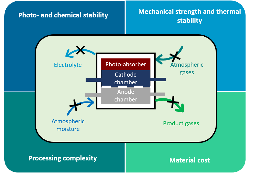
2.2.1. Importance of Hermetic Sealing in PEC Devices
2.2.2. Risks and Hazards Associated with PEC Operation
2.2.3. Reliability and Durability in the Context of PEC Device Operation
3. General Considerations for Hermetic Sealing of PEC Devices
3.1. Operating Conditions
3.2. Conceivable Failure Modes That Could Cause Loss of Hermetic Sealing
3.3. Safety Issues
3.4. Demands on PEC Device Encasement and Sealing Materials
4. State of the Art in Hermetic Sealing of PEC Devices
4.1. Compilation of Fully Functional PEC Systems
4.2. Critique of Candidate Materials for Hermetic Sealings
5. Perspectives and Future Research Directions
5.1. Possible Qualification and Safety Tests
5.2. Lessons from Related Electrochemical Devices
6. Discussion
7. Conclusions
Author Contributions
Funding
Acknowledgments
Conflicts of Interest
References
- Rongé, J.; Bosserez, T.; Martel, D.; Nervi, C.; Boarino, L.; Taulelle, F.; Decher, G.; Bordiga, S.; Martens, J.A. Monolithic cells for solar fuels. Chem. Soc. Rev. 2014, 43, 7963–7981. [Google Scholar] [CrossRef]
- Xiang, C.; Weber, A.Z.; Ardo, S.; Berger, A. Modeling, simulation, and implementation of solar-driven water-splitting devices. Angew. Chem. Int. Ed. 2016, 55, 12974–12988. [Google Scholar] [CrossRef]
- Bosserez, T.; Rongé, J.; van Humbeeck, J.; Haussener, S.; Martens, J. Design of compact photoelectrochemical cells for water splitting. Oil Gas Sci. Technol. Rev. IFP Energies Nouv. 2015, 70, 791–902. [Google Scholar] [CrossRef]
- Hu, S.; Lewis, N.S.; Ager, J.W.; Yang, J.; McKone, J.R.; Strandwitz, N.C. Thin-film materials for the protection of semiconducting photoelectrodes in solar-fuel generators. J. Phys. Chem. C 2015, 119, 24201–24228. [Google Scholar] [CrossRef]
- Nandjou, F.; Haussener, S. Degradation in photoelectrochemical devices: Review with an illustrative case study. J. Phys. D Appl. Phys. 2017, 50, 124002. [Google Scholar] [CrossRef]
- Ager, J.W.; Shaner, M.R.; Walczak, K.A.; Sharp, I.D.; Ardo, S. Experimental demonstrations of spontaneous, solar-driven photoelectrochemical water splitting. Energy Environ. Sci. 2015, 8, 2811–2824. [Google Scholar] [CrossRef]
- Kim, J.H.; Hansora, D.; Sharma, P.; Jang, J.-W.; Lee, J.S. Toward practical solar hydrogen production—An artificial photosynthetic leaf-to-farm challenge. Chem. Soc. Rev. 2019, 48, 1908–1971. [Google Scholar] [CrossRef]
- Ardo, S.; Rivas, D.F.; Modestino, M.A.; Greiving, V.S.; Abdi, F.F.; Llado, E.A.; Artero, V.; Ayers, K.; Battaglia, C.; Becker, J.P.; et al. Pathways to electrochemical solar-hydrogen technologies. Energy Environ. Sci. 2018, 11, 2768–2783. [Google Scholar] [CrossRef]
- Bard, A.J.; Memming, R.; Miller, B. Terminology in Semiconductor Electrochemistry and Photoelectrochemical Energy-Conversion-(Recommendations 1991). Pure Appl. Chem. 1991, 63, 569–596. [Google Scholar] [CrossRef]
- Beeson, H.; Woods, S. Guide for Hydrogen Hazards Analysis on Components and Systems, NASA Technical Memorandum, NASMTM-2003-212059. 2003. Available online: https://ntrs.nasa.gov/archive/nasa/casi.ntrs.nasa.gov/20040033949.pdf (accessed on 6 September 2019).
- European Industrial Gases Association. EIGA Doc. 04, Fire Hazards of Oxygen and Oxygen Enriched Atmospheres. 2018. Available online: https://www.eiga.eu/index.php?eID=dumpFile&t=f&f=3371&token=a378faf4d18ff8a6d1c208a4a3d32bce1d47f6bc (accessed on 6 September 2019).
- Sathre, R.; Scown, C.D.; Morrow, W.R.; Stevens, J.C.; Sharp, I.D.; Ager, J.W.; Walczak, K.; Houle, F.A.; Greenblatt, J.B. Life-cycle net energy assessment of large-scale hydrogen production via photoelectrochemical water splitting. Energy Environ. Sci. 2014, 7, 3264. [Google Scholar] [CrossRef]
- ISO. ISO 22734-1:2008 Hydrogen Generators Using Water Electrolysis Process—Part 1: Industrial and Commercial Applications; ISO: Geneva, Switzerland, 2008. [Google Scholar]
- ISO. ISO 22734-2:2011, Hydrogen Generators Using Water Electrolysis Process—Part 2: Residential Applications; ISO: Geneva, Switzerland, 2008. [Google Scholar]
- Shroeder, V.; Emonts, B.; Janßen, H.; Schulze, H.-P. Explosion limits of hydrogen-oxygen mixtures at initial pressures up to 200 bar. Chem. Eng. Technol. 2004, 27, 847–851. [Google Scholar] [CrossRef]
- Conrad, D.; Kaulbars, R. Druckabhaengigkeit der Explosionsgrenzen von Wasserstoff. Chem. Ing. Tech. 1995, 67, 185–188. [Google Scholar] [CrossRef]
- Ritchie, R.O. The conflicts between strength and toughness. Nat. Mater. 2011, 10, 817–822. [Google Scholar] [CrossRef] [PubMed]
- Becker, J.-P.; Turan, B.; Smirnov, V.; Welter, K.; Urbain, F.; Wolff, J.; Haas, S.; Finger, F. A modular device for large area integrated photoelectrochemical water-splitting as a versatile tool to evaluate photoabsorbers and catalysts. J. Mater. Chem. A 2017, 5, 4818. [Google Scholar] [CrossRef]
- Andrei, V.; Hoye, R.L.Z.; Crespo-Quesada, M.; Bajada, M.; Ahmad, S.; De Volder, M.; Friend, R.; Reisner, E. Scalable triple cation mixed halide perovskite–bivo4 tandems for bias-free water splitting. Adv. Energy Mater. 2018, 8, 1801403. [Google Scholar] [CrossRef]
- Vilanova, A.; Lopes, T.; Spenke, C.; Wullenkord, M.; Mendes, A. Optimized photoelectrochemical tandem cell for solar water splitting. Energy Storage Mater. 2018, 13, 175–188. [Google Scholar] [CrossRef]
- Tembhurne, S.; Nandjou, F.; Haussener, S. A thermally synergistic photo-electrochemical hydrogen generator operating under concentrated solar irradiation. Nat. Energy 2019, 4, 399–407. [Google Scholar] [CrossRef]
- Schröder, M.; Kailasam, K.; Borgmeyer, J.; Neumann, M.; Thomas, A.; Schomäcker, R.; Schwarze, M. Hydrogen evolution reaction in a large-scale reactor using a carbon nitride photocatalyst under natural sunlight irradiation. Energy Technol. 2015, 3, 1014–1017. [Google Scholar] [CrossRef]
- Fallisch, A.; Schellhase, L.; Fresko, J.; Zedda, M.; Ohlmann, J.; Steiner, M.; Boesch, A.; Zielke, L.; Thiele, S.; Dimroth, F.; et al. Hydrogen concentrator demonstrator module with 19.8% solar-to-hydrogen conversion efficiency according to the higher heating value. Int. J. Hydrogen Energy 2017, 42, 26804–26815. [Google Scholar] [CrossRef]
- Verlage, E.; Shu, H.; Liu, R.; Jones, R.J.R.; Sun, K.; Xiang, C.; Lewis, N.S.; Atwater, H.A. A monolithically integrated, intrinsically safe, 10% efficient, solar-driven water-splitting system based on active, stable earth-abundant electrocatalysts in conjunction with tandem III–V light absorbers protected by amorphous TiO2 films. Energy Environ. Sci. 2015, 8, 3166–3172. [Google Scholar] [CrossRef]
- Walczak, K.; Chen, Y.; Karp, C.; Beeman, J.W.; Shaner, M.; Spurgeon, J.; Sharp, I.D.; Amashukeli, X.; West, W.; Jin, J.; et al. Modeling, simulation, and fabrication of a fully integrated, acid-stable, scalable solar-driven water-splitting system. ChemSusChem 2015, 8, 544–551. [Google Scholar] [CrossRef] [PubMed]
- Walczak, K.A.; Segev, G.; Larson, D.M.; Beeman, J.W.; Houle, F.A.; Sharp, I.D. Hybrid composite coatings for durable and efficient solar hydrogen generation under diverse operating conditions. Adv. Energy Mater. 2017, 7, 1602791. [Google Scholar] [CrossRef]
- Kistler, T.A.; Danilovic, N.; Agbo, P. A monolithic photoelectrochemical device evolving hydrogen in pure water. J. Electrochem. Soc. 2019, 166, H656–H661. [Google Scholar] [CrossRef]
- Modestino, M.A.; Walczak, K.A.; Berger, A.; Evans, C.M.; Haussener, S.; Koval, C.; Newman, J.S.; Ager, J.W.; Segalman, R.A. Robust production of purified H2 in a stable, self-regulating, and continuously operating solar fuel generator. Energy Environ. Sci. 2014, 7, 297–301. [Google Scholar] [CrossRef]
- Wullenkord, M.; Spenke, C.; Vilanova, A.; Lopes, T.; Mendes, A. Public report on performance of the large-area prototype array, Project Deliverable Report—D6.4, Photoelectrochemical Demonstrator Device for Solar Hydrogen Generation (PECDEMO). 2017. Available online: https://archiveweb.epfl.ch/pecdemo.epfl.ch/files/content/sites/pecdemo/files/public%20files/PECDEMO%20Deliverable%206.4_DLR_UPorto.pdf (accessed on 30 September 2019).
- Bicer, Y. Investigation of Novel Ammonia Production Options Using Photoelectrochemcial Hydrogen. Ph.D. Thesis, University of Ontario, Oshawa, ON, Canada, 2017. Available online: https://ir.library.dc-uoit.ca/bitstream/10155/780/1/Bicer_Yusuf.pdf (accessed on 30 September 2019).
- Goto, Y.; Hisatomi, T.; Wang, Q.; Higashi, T.; Ishikiriyama, K.; Maeda, T.; Sakata, Y.; Oku, S.; Tokudome, H.; Katayama, M.; et al. A particulate photocatalyst water-splitting panel for large-scale solar hydrogen generation. Joule 2018, 2, 509–520. [Google Scholar] [CrossRef]
- Tolod, K.R.; Hernández, S.; Russo, N. Recent Advances in the BiVO4 Photocatalyst for Sun-Driven Water Oxidation: Top-Performing Photoanodes and Scale-Up Challenges. Catalysts 2017, 7, 13. [Google Scholar] [CrossRef]
- Available online: https://www.stratasys.com/materials/search/ (accessed on 28 August 2019).
- Welter, K.; Hamzelui, N.; Smirnov, V.; Becker, J.-P.; Jaegermann, W.; Finger, F. Catalysts from earth abundant materials in a scalable, stand-alone photovoltaic electrochemical module for solar water splitting. J. Mater. Chem. A 2018, 6, 15968–15976. [Google Scholar] [CrossRef]
- Cardarelli, F. Materials Handbook, A concise Desktop Reference, 2nd ed.; Springer Verlag: London, UK, 2008. [Google Scholar]
- Henager, C.H. Hydrogen Permeation Barrier Coatings, Materials for the Hydrogen Economy; Jones, R.H., Thomas, G.J., Eds.; CRC Press: Boca Raton, FL, USA, 2007; Chapter 8; pp. 181–190. [Google Scholar]
- Barth, R.R.; Simmons, K.L.; San Marchi, C. Polymers for Hydrogen Infrastructure and Vehicle Fuel Systems: Applications, Properties and Gap Analysis; Sandia Report; Sandia National Laboratories: Alberquerque, New Mexico; Livermore, CA, USA, October 2013; SAND2013-8904. Available online: https://prod-ng.sandia.gov/techlib-noauth/access-control.cgi/2013/138904.pdf (accessed on 18 September 2019).
- Jung, H.Y.; Huang, S.Y.; Popov, B.N. High-durability titanium bipolar plate modified by electrochemical deposition of platinum for unitized regenerative fuel cell (URFC). J. Power Sour. 2010, 195, 1950–1956. [Google Scholar] [CrossRef]
- Kuromoto, N.K.; Simao, R.A.; Soares, G.A. Titanium oxide films produced on commercially pure titanium by anodic oxidation with different voltages. Mater. Charact. 2007, 58, 114–121. [Google Scholar] [CrossRef]
- Kongstein, O.E.; Guillet, N.; Ødegård, A. WP5 “Porous Current Collectors and Materials for Bipolar Plate”, Bibliographic Review. NEXPEL Project, Next-Generation PEM Electrolyzer for Sustainable Hydrogen Production. 2010. Available online: https://www.sintef.no/globalassets/project/nexpel/pdf/nexpelwp5-bibliographicreview--rt-deht-dr10-051-final.pdf (accessed on 26 July 2019).
- Lettenmeier, P.; Wang, R.; Abouatallah, R.; Burggraf, F.; Gago, A.S.; Friedrich, K.A. Coated stainless steel bipolar plates for proton exchange membrane electrolyzers. J. Electrochem. Soc. 2016, 163, F3119–F3124. [Google Scholar] [CrossRef]
- Yeetsorn, R.; Fowler, M.W.; Tzoganakis, C. A Review of Thermoplastic Composites for Bipolar Plate Materials in PEM Fuel Cells, Nanocomposites with Unique Properties and Applications in Medicine and Industry; Cuppoletti, J., Ed.; Intech Open: Rijeka, Croatia, 2011; Available online: https://www.intechopen.com/books/nanocomposites-with-unique-properties-and-applications-in-medicine-and-industry/a-review-of-thermoplastic-composites-for-bipolar-plate-materials-in-pem-fuel-cells (accessed on 8 September 2019). [CrossRef]
- Yde, L.; Kjartansdóttir, C.K.; Allebrod, F.; Mogensen, M.B.; Møller, P.; Hilbert, L.R.; Nielsen, P.T.; Mathiesen, T.; Jensen, J.; Andersen, L.; et al. Generation Alkaline Electrolysis, 2nd ed.; Final report; Århus University Business and Social Science–Centre for Energy Technologies: Aarhus, Denmark, 2013. [Google Scholar]
- Hydrogen from RES: Pressurised Alkaline Electrolyser with High Efficiency and Wide Operating Range, RESelyser, Final Project Report. 2015. Available online: http://www.reselyser.eu/resources/RESelyser_final_publishable_290615.pdf (accessed on 10 September 2019).
- Henkel. LOCTITE EA 9460, Technical Data Sheet. December 2013. Available online: https://tdsna.henkel.com/americas/na/adhesives/hnauttds.nsf/web/E26C4A5F8C916DE2882571870000DB25/$File/EA%209460-EN.pdf (accessed on 30 September 2019).
- Henkel. LOCTITE EA 9492; Technical Data Sheet; Henkel: Düsseldorf, Germany, 2014. [Google Scholar]
- Henkel. LOCTITE EA 9483; Technical Data Sheet; Henkel: Düsseldorf, Germany, 2008. [Google Scholar]
- James, T.H.; Michael, C.S. Electrolyser and Components Therefor. U.S. Patent 8,057,646B2, 15 November 2011. [Google Scholar]
- Marchi, C.S. Nonmetals: Polymers (code 8100). In Technical Reference on Hydrogen Compatibility of Materials; Marchi, C.S., Somerday, B.P., Eds.; Sandia National Laboratories: Livermore, CA, USA, 2008. Available online: http://www.ca.sandia.gov/matlsTechRef/ (accessed on 10 September 2019).
- Dunlop, E.D.; Gracia Amillo, A.; Salis, E.; Sample, T.; Taylor, N. Standards for the Assessment of the Environmental Performance of Photovoltaic Modules, Power Conditioning Components and Photovoltaic Systems; EUR 29247 EN.; Publications Office of the European Union: Luxembourg, 2018; ISBN 978-92-79-86608-1. [Google Scholar] [CrossRef]
- Chisholm, G.; Kitson, P.J.; Kirkaldy, N.D.; Bloor, L.G.; Cronin, L. 3D printed flow plates for the electrolysis of water: An economic and adaptable approach to device manufacture. Energy Environ. Sci. 2014, 7, 3026–3032. [Google Scholar] [CrossRef]
- Stewart, I.; Mcgowan, D.; Gallagher, E. Seal for Solid Polymer Electrolyte Fuel Cell. Patent WO201613078118, 18 August 2016. [Google Scholar]
- Chen, R.; Kaye, I. Modular, High-Volume Fuel Cell Leak-Test Suite and Process (Phase I); Final Technical Report; 2012. Available online: https://www.osti.gov/servlets/purl/1036158 (accessed on 10 September 2019). [CrossRef]
- Lin, C.-K.; Liu, Y.-A.; Wu, S.-H.; Liu, C.-K.; Lee, R.-Y. Joint strength of a solid oxide fuel cell glass–ceramic sealant with metallic interconnect in a reducing environment. J. Power Sour. 2015, 280, 272–288. [Google Scholar] [CrossRef]
- Fairweather, M.J.; Topping, J.A. Alkaline Battery Seal. Patent US 3957538A, 18 May 1976. [Google Scholar]
- HyProvide Large-Scale Alkaline Electrolyser [MW], Final Project Report. 2016. Available online: https://www.energiteknologi.dk/sites/energiteknologi.dk/files/slutrapporter/final_report_hyprovide_64011-0105_rev_03.pdf (accessed on 10 September 2019).
- Zito, R., Jr. Zinc-Bromine Battery with Long Term Stability. U.S. Patent US4482614A, 13 November 1984. [Google Scholar]
- Nakaishi, H.; Kanno, T.; Ogino, S.; Ito, T.; Shigematsu, T.; Tokuda, N. Cell Frame for Redox-Flow Cell and Redox-Flow Cell. Patent Application US20040202915A1, 14 October 2004. [Google Scholar]
- Rongé, J.; Deng, S.; Pulinthanathu Sree, S.; Bosserez, T.; Verbruggen, S.W.; Kumar, S.N.; Dendooven, J.; Roeffaers, M.B.J.; Taulelle, F.; De Volder, M.; et al. Air-based photoelectrochemical cell capturing water molecules from ambient air for hydrogen production. RSC Adv. 2014, 4, 29286–29290. [Google Scholar] [CrossRef]


| Solar Collection Area (cm2) | Rate of H2 Production g/h (a) | STH | Photoabsorber; | Electrolyte; OER; HER | Structural Material of Casing | Edge Sealing Material and Technique | Figure | Year [Reference] |
|---|---|---|---|---|---|---|---|---|
| 0.36 (PV cell) 90.7 (Fresnel lens) | 153 × 10−3 (252 suns) | ~19 | III-V dual junction | Nafion; Ir; carbon supported Pt | Titanium anode plate clamped with polyphenylene sulfide (PPS) cathode plate. | Screw compressed o-rings of undisclosed material | -/- | 2017 [23] |
| 1 | 98.2 × 10⁻³ | 8.6 | GaAs/InGaP photoanode | 1.0 M KOH | 3-D printed acrylic with a quartz window | Fluorosilicone O-ring seals clamped using bolts and/or epoxy (Loctite 9460, Hysol) | -/- | 2015 [24] |
| 1 | 323 × 10−6 | 10.6 | InGaP/GaAs/Ge | Nafion XL-100 in 1MH2SO4; IrOx;Pt | Machined acrylic with quartz window | Viton O-ring clamped using bolts; window and flow fittings sealed with Epo-TekTM 302-3M epoxy | -/- | 2017 [26] |
| 1 | 386 × 10−6 | 12.6 | GaInP2/InGaAs/Ge | Nafion 115-100 in 1MH2SO4; Irx;Pt | PMMA plates with quartz window | Electrolysis compartment sealed using screw compressed silicone seals; Seal between window and PV device, and electrolysis cell used an epoxy mix consisting of Loctite 9460, Hysol and EPO-TEKTM | -/- | 2019 [27] |
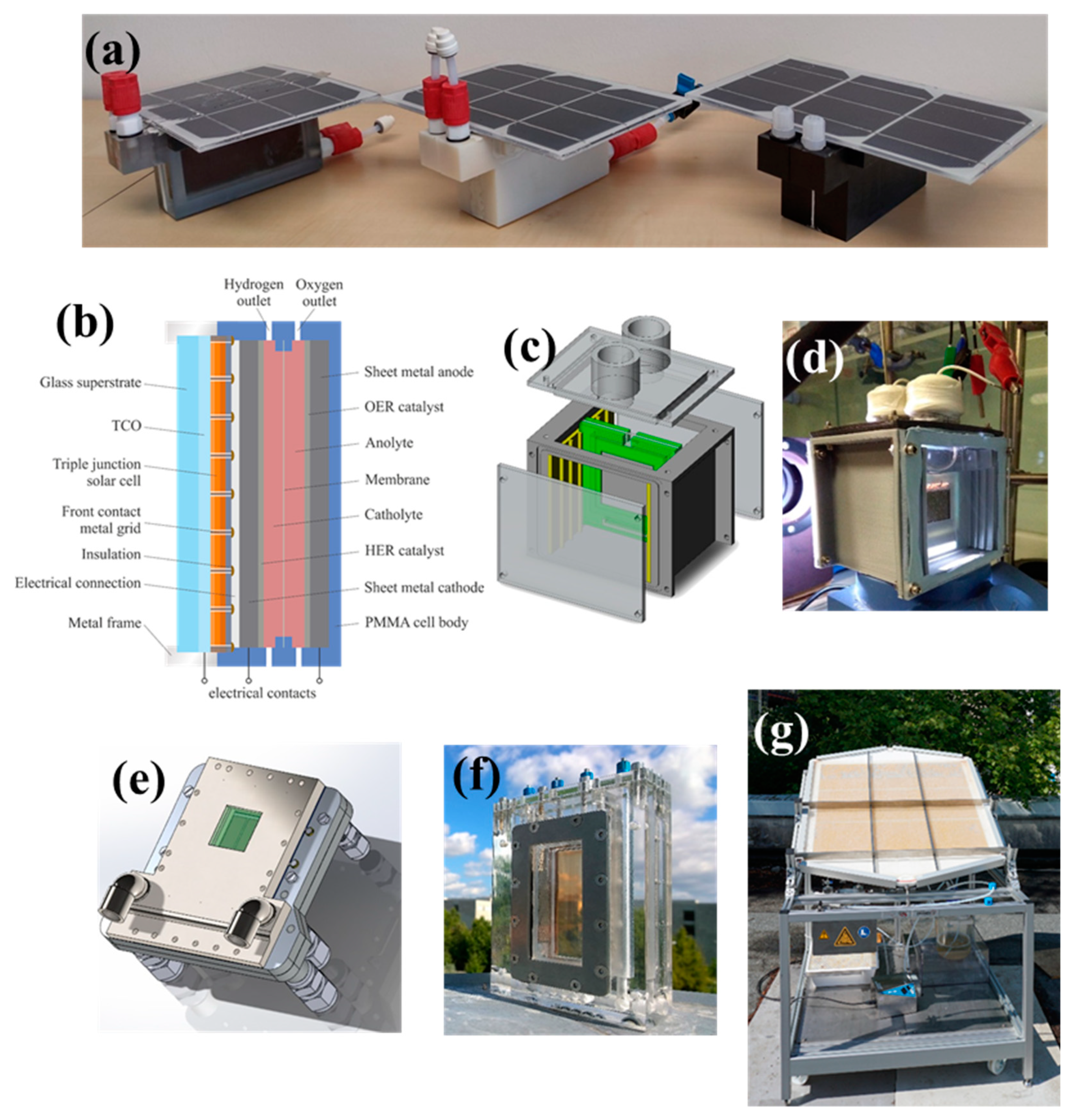
| 4 | 230 × 10−3 at 117 suns; 1.09 at 473.54 suns | 19 | 4 cells in parallel (InGaP-InGaAs-Ge) | Nafion 115 in pure water; IrRuOx/Pt | (3-D)-printed titanium alloy Ti6Al4V with glass window for illumination | Screw compressed (undisclosed material) seals, epoxy seal between electrolysis chamber and PV cell | 1 (e) | 2019 [21] |
| 10 | 45.2 × 10⁻⁶ (b) | 0.15 | Lead halide perovskite-BiVO4 tandem | 0.1 M KBi, K2SO2 (pH 8.50) | 3-D printed Polylactic acid with acrylic window | Window sealed with soft adhesive Blu Tack | 1 (c), 1 (d) | 2018 [19] |
| 26.6 | 5.1 × 10⁻³ (c) | 6.2 | GaInP2/GaAs/Ge PV cells; | 1.0 M potassium borate buffer (pH 9.3), Pt, Pt | 3-D printed (Fullcure RGD720) polymer with glass window | Not disclosed | -/- | 2014 [28] |
| ~30 (d) | 13.9 × 10⁻⁶ | 0.24% | WO3/FTO/p+n Si photo-anode and Pt/TiO2/Ti/n+p Si photocathode | Nafion (e); 1.0 M HClO4 | 3-D printed PMMA like polymer (RGD720) Glass window | Adhesive epoxy Loctite 9460, Hysol | -/- | 2015 [25] |
| 50 | Not measured | 0.64 (f) | Hematite with two silicon PV cells heterojunction solar cells, | 1.0 M KOH; not disclosed | PMMA casing, stainless steel frames supporting front quartz window and rear glass photo-electrode substrate | Sealing via clamping gaskets with screws | 1 (f) | 2018 [20] |
| 64 | 24.5×10⁻³ at AM 1.5G | 4.8 | Multi-junction thin film silicon based PV cells | 1.0 M KOH | Machined PMMA and glass window substrate for the photo-absorber | Polyether ether ketone (PEEK) o-rings, clamping with epoxy | 1 (b) | 2017 [18] |
| 200 (combined PEC area) | 13.6 × 10⁻⁶ at 17.5 concentration (g) | -/- | Four sets in tandem each (BiVO4/BiVO4 in series with a silicon heterojunction PV cell | 0.5 M K2SO2 with 0.1 M K2HPO4/K2PO4 (pH 7); not disclosed | PMMA casing, stainless steel frames supporting front quartz window and rear glass photo-electrode substrate; PMMA casing protected on the illuminated side from overheating by concentrated sunlight using a PTFE/aluminium shield | Sealing via clamping gaskets (undisclosed material) with screws | -/- | 2017 [29] |
| 294 | 44.1 × 10⁻³ (h) | 6–10 | Three silicon heterojunction PV cells in series; | 1.0 M KOH; NiFeOx, NiMo | 3-D printed PMMA based Veroclear with solar glass window | LOCTITE EA9492 epoxy used to seal joint with PV module and joints of electrolysis cell | 1 (a) | 2019 [This work] |
| 820 (PEC cell aperture); 8760 (Fresnel lens) | 16.8 × 10⁻³ at 12 suns (i) | -/- | Cu2O photocathode, | Nafion, IrRuOx; Platinum black | PMMA end plates with Acrylonitrile Butadiene Styrene (ABS) frames supported by HDPE outer casing; Acrylic window | Nitrile rubber gaskets with bolted compression clamping | 2017 [30] | |
| 910 | 8.3 × 10⁻³ (j) | 0.12 | C3N4 photocathode; | H2O with 10% vol. Triethanolamine | Teflon plate, stainless steel and PMMA window | Metal braces | 1 (g) | 2015 [22] |
| 10,000 | 90.7 × 10⁻³ (k) | 0.4 | SrTiO3:Al | Water; RhCrOx | PMMA plates as window and rear support | Not disclosed | -/- | 2018 [31] |
| 16,000 | 3 (l) | 3 | CoPi catalyst on BiVO4:Mo and Co photocathode; | Not disclosed | Not disclosed | Not disclosed | -/- | 2017 [32] |
| Materials | Density (kg/m−3) | Elastic/Young’s Modulus E (GPa) | Compression/Bulk Modulus, K (GPa) | Ultimate Tensile Stress σUTS (MPA) | Impact Energy per Unit Width (J/m) (a) | Coefficient of Linear Thermal Expansion, αL (°10−6 K−1) | Min.- Max.- Operating Temperature (°C) | H2 Permeability (Mole H2/m s MPa] ~ 300 K, 1 Pa | Chemical Resistance to Hot KOH; H2SO4 (b) |
|---|---|---|---|---|---|---|---|---|---|
| Metals | |||||||||
| Nickel | 8902 | 199.5 | -/- | 403–462 | -/- | 13.3 | n/a | 1.2 × 10⁻¹⁰ | Good; fair |
| Austenitic stainless steel 316L | 8000 | 192–200 | -/- | 450–620 | -/- | 15.9 | n/a | 0.7–1.2 × 10⁻¹¹ | Fair; fair |
| Titanium | 4540 | 120.2 | 108.4 | 235 | -/- | 8.35 | -/- | 7 × 10⁻¹⁶ | Poor; poor |
| Ti-6Al-4V | 4420 | 106–114 | -/- | -/- | 24 | 9.2 | -/- | -/- | Fair; fair |
| Ceramics | |||||||||
| Quartz/silica | 2202–2650 | 72.95 | -/- | 69–276 | -/- | 0.55 | -/- | -/- | Good; good |
| Soda lime/float glass | 2530 | 72 | -/- | -/- | -/- | 8.9 | -/- | -/- | Poor; good |
| Borosilicate glass | 2510 | 82 | -/- | -/- | -/- | 0.90-1.10 | -/- | -/- | Poor; good |
| Sapphire glass/fused Al2O3 | 3980 | 379 | -/- | -/- | -/- | 8.3 | -/- | ~9 × 10⁻¹⁷ | Good; good |
| Thermoplastics | |||||||||
| PMMA | 1180–1190 | 3.03 | 2.55-3.17 | 72.4 | 16–32 | 34–77 | −40, 50–90 | 1.24 × 10⁹ | Fair; fair |
| PEEK | 1320 | 3.7–4.0 | -/- | 70-100 | 85 | 26–108 | -/-, 250 | 0.36–1.2 × 10⁹ | Good; good |
| Polysulfone PSU | 1240 | 2.48 | 2.58 | -/- | 69 | 31–51 | -/-,-/- | -/- | Fair; fair |
| PTFE | 2130–2220 | 0.48–0.76 | 0.41 | 10–40 | 160 | 100–160 | −260, 180–260 | 3.3 × 10⁹ | Good; good |
| Polylactic acid | 1250 | -/- | -/- | 48.3–145 | 12.8–29 | Not given | -/- | -/- | -/-; -/- |
| Rubbers and elastomers | |||||||||
| EPDM Ethylene propylene diene | 850 | -/- | -/- | 21 | n/a | Not given | -50, 150 | 17-14×109 | Good; -/- |
| Polysiloxanes (silicones) | -/- | -/- | -/- | 6.5 | n/a | -/- | -60, 232 | -/- | Poor; poor |
| Fluoroelastomers (e.g., Viton) | 1800–1860 | 2.07–15.17 | -/- | 4.8–11.0 | n/a | -/- | -29, 204 | 3.5–7.3 × 10⁹ | Fair; -/- |
| Thermosets | |||||||||
| Epoxy resin | -/- | -/- | -/- | -/- | -/- | 200–260 | -/- | ~0.57 × 10⁹ | -/-; -/- |
| LOCTITE® EA 9483 | 1050–1110 | 2.1 × 10⁻³ | -/- | -/- | -/- | 50–164 | -/- | -/- | Poor; poor |
| LOCTITE® EA 9492 | 6.7 × 10⁻³ | -/- | -/- | -/- | 63 | -/- | -/- | Fair;-/- | |
| LOCTITE® Hysol EA 9460 | 1330 | 2.76 × 10⁻³ | -/- | -/- | -/- | -/- | -/- | -/- | Poor; poor |
| 3-D Printed polymers (c) | |||||||||
| Fullcure RGD720 | -/- | 2–3 | -/- | 55–60 | -/- | -/- | -/- | -/- | -/-; -/- |
| VeroClear, RGD810; | -/- | 2–3 | -/- | 50–65 | 20–30 | -/- | 45–50 | -/- | Fair; -/- |
| Objet-RGD525-High-Temperature-White | -/- | 3.2–3.5 | -/- | 70–80 | 14–16 | -/- | 63–67 after post treatment 75–80 | -/- | Poor; -/- |
| VeroBlackPlus, RGD875. | -/- | 2.2 | -/- | 51 | 24 | -/- | 43 | -/- | Fair; -/- |
| Failure | Cause/Stress Factors | Implication | Possible PV Test | Possible Electrolyser and Fuel Cell Test |
|---|---|---|---|---|
| (Electro-chemical, photo) corrosion | pH, temperature extremes, temperature cycling, bias potential | Possible mechanical failure, contamination | Dry heat conditioning, ultra- violet radiation (UV) testing, damp heat, outdoor exposure | Corrosion test |
| Device fracture | Explosion, over pressure, temperature shocks, mechanical impact, temperature and/or pressure fluctuations | Catastrophic structural failure of encasement, broken electrical interconnects, photo-absorber cells, windows | Hail test, Module breakage test, long term outdoor exposure | Pressure drop test |
| Fatigue cracking | Temperature and/or pressure cycling, mechanical stress, extended UV exposure, hydrogen embrittlement, oxidation | Cracked photo-absorbers, substrates or encasement, delaminated coatings, broken interconnects, sealing joints and front window | Dynamic mechanical loading; damp heat; freeze-thaw cycling, hail test; outdoor exposure, cold and/or dry heat conditioning | Vibration test, temperature and/or pressure cycling, |
| Distortion or deformation | Over pressure, over-heating, fire | Catastrophic failure of entire device; leaks | Ignitability test if polymeric materials are used | Pressure drop test |
| Sealing joint failure | Delamination of adhesive at joints, temperature and/or pressure cycling, mechanical stress; corrosion and penetration of moisture | Loss of adhesion of epoxies and glues if used, delamination of functional coatings | Humidity freeze, outdoor exposure, peel test for cemented joints, lap shear strength test, materials creep test | Damp heat;pressure drop test |
| Ground faults | Wet leakage current | Electrical shock, increased risk of fire and/or explosion | Damp heat; ignitability test if polymeric materials are used | Dry and wet insulation resistance |
© 2019 by the authors. Licensee MDPI, Basel, Switzerland. This article is an open access article distributed under the terms and conditions of the Creative Commons Attribution (CC BY) license (http://creativecommons.org/licenses/by/4.0/).
Share and Cite
Calnan, S.; Aschbrenner, S.; Bao, F.; Kemppainen, E.; Dorbandt, I.; Schlatmann, R. Prospects for Hermetic Sealing of Scaled-Up Photoelectrochemical Hydrogen Generators for Reliable and Risk Free Operation. Energies 2019, 12, 4176. https://doi.org/10.3390/en12214176
Calnan S, Aschbrenner S, Bao F, Kemppainen E, Dorbandt I, Schlatmann R. Prospects for Hermetic Sealing of Scaled-Up Photoelectrochemical Hydrogen Generators for Reliable and Risk Free Operation. Energies. 2019; 12(21):4176. https://doi.org/10.3390/en12214176
Chicago/Turabian StyleCalnan, Sonya, Stefan Aschbrenner, Fuxi Bao, Erno Kemppainen, Iris Dorbandt, and Rutger Schlatmann. 2019. "Prospects for Hermetic Sealing of Scaled-Up Photoelectrochemical Hydrogen Generators for Reliable and Risk Free Operation" Energies 12, no. 21: 4176. https://doi.org/10.3390/en12214176
APA StyleCalnan, S., Aschbrenner, S., Bao, F., Kemppainen, E., Dorbandt, I., & Schlatmann, R. (2019). Prospects for Hermetic Sealing of Scaled-Up Photoelectrochemical Hydrogen Generators for Reliable and Risk Free Operation. Energies, 12(21), 4176. https://doi.org/10.3390/en12214176