Effect of Syngas Composition on the Combustion and Emissions Characteristics of a Syngas/Diesel RCCI Engine
by
 , ,
, ,
Navid Kousheshi
1 ,
,
Mortaza Yari
1,
Amin Paykani
2,*,
Ali Saberi Mehr
3 and
German F. de la Fuente
4 1
Faculty of Mechanical Engineering, University of Tabriz, Tabriz 5166616471, Iran
2
School of Engineering and Computer Science, University of Hertfordshire, Hatfield AL10 9AB, UK
3
Faculty of Mechanical Engineering, University of Bonab, Bonab 5551761167, Iran
4
Instituto de Ciencia de Materiales de Aragón (Universidad de Zaragoza-CSIC), María de Luna 3, 50018 Zaragoza, Spain
*
Author to whom correspondence should be addressed.
Energies 2020, 13(1), 212; https://doi.org/10.3390/en13010212
Submission received: 7 December 2019
/
Revised: 17 December 2019
/
Accepted: 23 December 2019
/
Published: 2 January 2020
(This article belongs to the Special Issue Fuel and Engine Design for Future Thermal Propulsion Systems)
Abstract
:Reactivity controlled compression ignition (RCCI) strategy uses two different fuels with different reactivities which provides more control over the combustion process and has the potential to dramatically lower combustion temperature and NOX and PM emissions. The objective of the present study is to numerically investigate the impact of syngas composition on the combustion and emissions characteristics of an RCCI engine operating with syngas/diesel at constant energy per cycle. For this purpose, different syngas compositions produced through gasification process have been chosen for comparison with the simulated syngas (mixture of hydrogen and carbon monoxide). The results obtained indicate that using syngas results in more soot, CO and UHC emissions compared with simulated syngas. Even though more NOX reduction can be achieved while operating with syngas, the engine could suffer from poor combustion and misfire at low loads due to the presence of nitrogen in the mixture. In terms of exergy, both syngas mixtures lead to more exergy destruction by the increase of syngas substitution. Nevertheless, the magnitude of exergy destruction for simulated syngas is less than the normal syngas.
1. Introduction
Highly premixed compression ignition strategies have been proposed as emerging engine technologies by many researchers to decrease the heterogeneous nature of the combustion [1,2,3]. Most of these strategies are lumped into the low-temperature combustion (LTC) category [4,5,6], where lower combustion temperatures inhibit NOX formation and longer ignition delay times provide adequate time for better mixing and avoid local fuel rich islands, leading to lower soot formation. The LTC strategy includes homogeneous charge compression ignition (HCCI), partially premixed compression ignition (PPC), and reactivity controlled compression ignition (RCCI) concepts [7]. In order to overcome the disadvantages of HCCI and PPC strategies in terms of direct combustion rate control [8,9], RCCI combustion has been introduced. Kokjohn et al. [10] showed a high potential of combustion controllability with RCCI combustion which was achieved by blending two fuels with different reactivities inside the cylinder. In RCCI combustion, a fuel with a low reactivity (e.g., gasoline) is blended with air before entering to the combustion chamber and a fuel with higher reactivity (e.g., diesel) is directly injected through injectors. This method allows the combustion phasing to be controlled by the ratio of these different fuels. By using this technique, in-cylinder stratification can control the combustion duration as well.
Application of alternative fuels and exploring their effects on the performance and emissions characteristic of RCCI engines have been conducted by many researchers. The use of the gasoline and diesel in light and heavy-duty engines was proposed by Kokjohn et al. [11]. The results indicated high thermal efficiency with low emissions which are simultaneously achieved by reactivity controlled compression ignition strategy. Walker et al. [12] utilized methane instead of gasoline in an RCCI engine, and discovered that higher loads could be achieved with methane/diesel instead of gasoline/diesel. A similar study was performed by Nieman et al. [13] and showed that natural gas surpasses gasoline performance due to its higher octane number. A large reactivity gradient between these fuels could be useful in controlling the maximum PRR. Alcoholic fuels (i.e., methanol, ethanol, etc.) can be also considered as candidates for low reactivity fuel. Dempsey et al. [14] studied a heavy-duty RCCI engine combustion process using the mixture of hydrated ethanol-diesel. The results showed that the fuel’s local reactivity can be properly controlled in this way, and combustion timing and duration can be easily determined. Benajes et al. [15] used different gasoline and ethanol blends in an RCCI engine, and tested the engine performance from low to high loads. They found that a premixed ratio of 85% of ethanol (in volume) will be needed in order to reach a stable combustion. Several studies have been also performed by researchers to investigate the effects of various parameters including fuel ratio, injection strategy, bowl geometry and etc. on the combustion and emissions of RCCI engines [9,16].
Recently, a considerable attention has been given to syngas as a low reactivity fuel. Syngas (an abbreviation for synthesis gas) also called producer gas or wood gas, is mainly a blend of nitrogen (N2), carbon monoxide (CO), hydrogen (H2), methane (CH4), and small fraction of carbon dioxide (CO2). Syngas can be produced by the gasification process of a carbon-containing fuel, such as biomass, natural gas, heavy oil and coal. Syngas can also be produced through fuel reforming with steam and/or air using compact systems, which can be mounted onboard on a vehicle. In-cylinder and external on-board fuel reforming have been identified as a potential way to improve IC engine efficiency and emissions. Sahoo et al. [17] and Bika et al. [18] separately studied the effects of the H2/CO ratio in the syngas on the performance and emissions of a dual fuel diesel engine. Their research implied that the higher amounts of H2 results in higher engine NOX emissions, lower CO and UHC (unburned hydrocarbons) and better brake thermal efficiencies. Moreover, the amount of CO in products depends mainly on the CO amount in the syngas.
Rahnama et al. [19] investigated the use of reformer gas produced onboard by a catalytic fuel reformer as an additive in a natural gas/diesel RCCI engine. They concluded that reformate could improve the engine combustion process at low loads since it enhances the burning rate and compensate the low reactivity of natural gas. In another study the effect of adding hydrogen, reformer gas, nitrogen, and a mixture of hydrogen and nitrogen on ignition delay, pressure rise rate, and ringing intensity was investigated by them [20]. The results indicated that combustion was improved at low engine load by using hydrogen and syngas. In addition, it was found that stable combustion and a low pressure rise rate could be achieved at 17 bar IMEP at the expense of higher carbon emissions with nitrogen-rich intake air. Chuahy et al. [21,22] used the RCCI concept to investigate the effects of reformate (containing CO and H2) on the combustion. The results of this study showed that the use of this syngas as the low reactivity fuel is possible over a wide range of H2/CO ratios. They also indicated that larger amounts of H2 in syngas composition would result in more reactive fuel which decreases the duration of combustion and suppresses low-temperature heat release as well. In another study, Chuahy et al. [23] experimentally investigated an ideal syngas composed of 50% hydrogen and 50% carbon monoxide by volume on a RCCI Engine. Results showed the simultaneous reduction of NOX and soot emissions, however, the amount of CO increased by the increase of diesel substitution fraction with syngas. An optimization on important operating parameters such as supply of the fuel, the composition of syngas, and condition of intake on a syngas/diesel RCCI engine was conducted by Jia et al. [24]. The results of this study under a wide load showed that NOX could be kept in low rates, and reaching the efficient combustion can be simple in high premix ratio regions and early pilot injection of diesel. Results also showed the optimal H2 fraction should be 60–80% and with 75%, the engine has the ability to achieve high thermal efficiency at full load.
The effect of hydrogen addition on engine knock in spark ignition engines was assessed by Rutland et al. [25]. Lowering fuel reactivity due to hydrogen addition, in some operating conditions, was one of the results which leads to the increase of the knock resistance. A CFD analysis of syngas-biodiesel combustion on a CI engine was performed by Costa et al. [26]. The results showed that adding syngas (produced from gasification of rubber wood) to the biodiesel, in return for increasing thermal efficiency reduces the combustion efficiency. Like the rest, decreasing NOX formation in exchange for more soot and CO, was reported.
According to the literature, it was found that there has been no research in which the actual syngas obtained from various methods of reforming and gasification, is used as the second fuel with low reactivity in RCCI engines. Most of the researchers assume the first two species (H2 and CO) and use this blend as a simulated syngas instead of the actual ones by neglecting the other species. Hence the present study is conducted to numerically evaluate the potential of using various types of syngas mixtures and assess their effects on combustion process and emission characteristics in a syngas-diesel RCCI engine. Three types of syngas gases are selected for comparison with the simulated syngas comprised solely of hydrogen and carbon monoxide. For all cases, a premixed substitution ratio sweep at constant fuel energy is utilized to investigate their effects on emissions and the overall performance. After all, a first and second law analysis are performed to compare the efficiencies and estimate opportunities for further researches.
2. Simulation Modeling and Methods
The RCCI engine, as well as models and sub-models used to compute the simulation of the system, are discussed in the following sections.
2.1. Engine Modeling
The engine utilized and modeled throughout this work is a Caterpillar 3401 Single Cylinder Oil Test Engine (SCOTE) being experimentally used by Chuahy et al. [23] at the Engine Research Center, Madison. The engine is typical of a heavy-duty size-class diesel engine whose specifications could be found in Table 1.
2.2. CFD Models and Sub-Models
The combustion computational modeling employed for the simulation of this study was performed by CONVERGE version 2.3.5 [27]. Table 2 shows the sub-models used for this work.
CONVERGE uses Lagrangian droplet approach for the spray sub-model. The spray atomization model used for spray computations follows the KH-RT hybrid approach [28].
The Frossling Correlation model [29] was employed by CONVERGE CFD to calculated the multicomponent vaporization. Turbulence flow was calculated from the re-Normalization Group (RNG) k-ε model introduced by Han et al. [30] which takes into account the effects of compressibility. No Time Counter (NTC) approach proposed by Schmidt et al. [31] been used to model the droplet collision. The dynamic drag model was utilized in droplet drag calculations [32]. Droplet film formation is also modeled by O’Rourke model [33]. NOX emissions were predicted using an extended Zeldovich method [34]. A phenomenological model has been utilized to calculate soot emissions [34] in accordance with the approach of Hiroyasu [35] which calculates the rate of change of soot mass by:
where and are soot’s formation and oxidation rates respectively. Soot’s formation is also proposed by the Arrhenius type expression:
where, is the mass of acetylene which is utilized as the inception species for the formation of soot. and are empirical tuning parameters and R is the ideal gas constant. P and T are the cell pressure and the cell temperature respectively. The factor of soot pre-exponential and activation energy in the formation rate has been calibrated with experimental data [23]. CONVERGE uses the SAGE detailed chemical kinetics solver [36] for combustion modeling. SAGE model determines the rates of reaction for each elementary reaction which is utilized to update the concentration of species at each time step. The direct-injected fuel’s physical properties and chemical kinetics were specified by tetradecane (C14H30) as a diesel surrogate and n-heptane respectively. The results were obtained using a multi-fuel mechanism developed by Ren et al. [37] with 178 species and 758 reactions which has the capability to model diesel and syngas combustion with high accuracy because of incorporating the reaction mechanisms of H2/CO/O2 [38]. Moreover, for computational efficiency improvement, the multi-zone chemistry solver is used for the present simulations [39].
2.3. Engine Exergitic Analysis
All models of the current study have been performed in a close cycle which starts from inlet valve close state (IVC) and ends at exhaust valve open state (EVO). Hence, the balance of exergy for such a control mass system has to be defined as follows:
where is the net exergy transferred in or out of the system. and shows the exergy destruction and change in exergy of the whole system, respectively.
Thermomechanical exergy which is the combination of the thermal and mechanical exergy and also the chemical exergy of the intake and exhaust fluids predicted as follows:
where H and S are the exhaust gas enthalpy and entropy, respectively. T and are the temperatures at current and the reference dead state. and are the mole fractions of the jth component in the intake (or exhaust) gases and the reference dead state, respectively. R and k are the ideal gas constant and the number of species which are contained in the intake (or exhaust).
Fuel exergy () can be calculated through enthalpies and entropies of reactants and products [40,41,42]. Since complete combustion is assumed the reactants are fuel and O2 and the products consist of CO2 and H2O as follows:
Likewise, the transferred exergy through incomplete combustion products () is calculated in the same approach.
The exergy of heat loss which is related to the temperature gradients near the boundaries and output work in the engine are determined from the following equations:
where Q demonstrates the heat transfer, is the gas temperature in boundaries like walls. P and P0 are the pressures of the cylinder and reference dead state respectively. shows the variation of cylinder volume versus crank angle.
According to exergy balance and referring to the Equation (3), exergy destruction in the engine from IVC to EVO can be estimated as:
As a matter of fact, in real conditions, the process of heat transfer in an engine is complicated due to the fact that there are several boundaries through which the heat transfers out of the cylinder. In the present study, only the exergy of heat loss between the IVC and EVO states is estimated.
3. Computational Model Validation
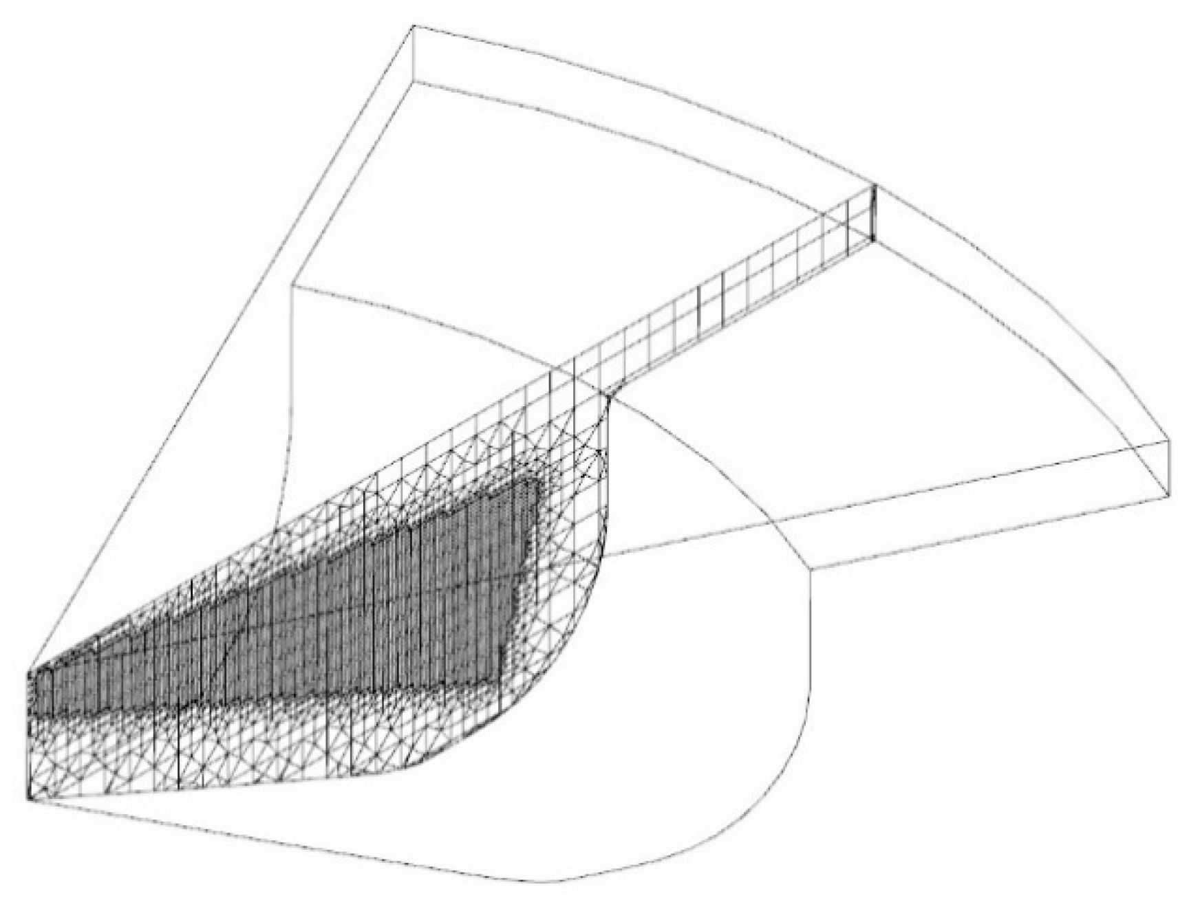
Based on less time, instead of the whole cylinder geometry, calculations were conducted on a sector with periodic boundaries. Since a seven-hole the injector was mounted on engine, a geometry of a sector with 51.42 degrees was created as shown in Figure 1. The fixed embedding option with the length of 0.06 m for covering the liquid and parcel fuel areas, around the injector, was activated to make the calculations more precise. Having analyzed the primary results of grid sensitivity to ensure the grid independence, a 49,000-cell grid and a base cell with the size of 2 mm was chosen due to the best tradeoff between computational time and accuracy. To make the results reliable, created models of engines should be validated against the results in the literature. The present simulation validated against the experimental data reported by Chuahy et al. [23] at the University of Wisconsin-Madison.
Firstly, conventional diesel operations ranging from 0.36 to 0.58 of global equivalence ratios were chosen to validate the model. Secondly, the equivalence ratio of 0.43 had been selected to study diesel-syngas RCCI engine. In this stage, substitutions of 20%, 40% and 60% by energy, were conducted to evaluate the capability of reduced multi-fuel mechanism on predicting syngas combustion which were successfully validated. In all cases, a composition of 50% hydrogen and 50% carbon monoxide by volume is used as syngas. Amount of directly injected diesel was maintained constant for all CDC cases. Table 3 shows a summary of the test conditions for simulation results validation.
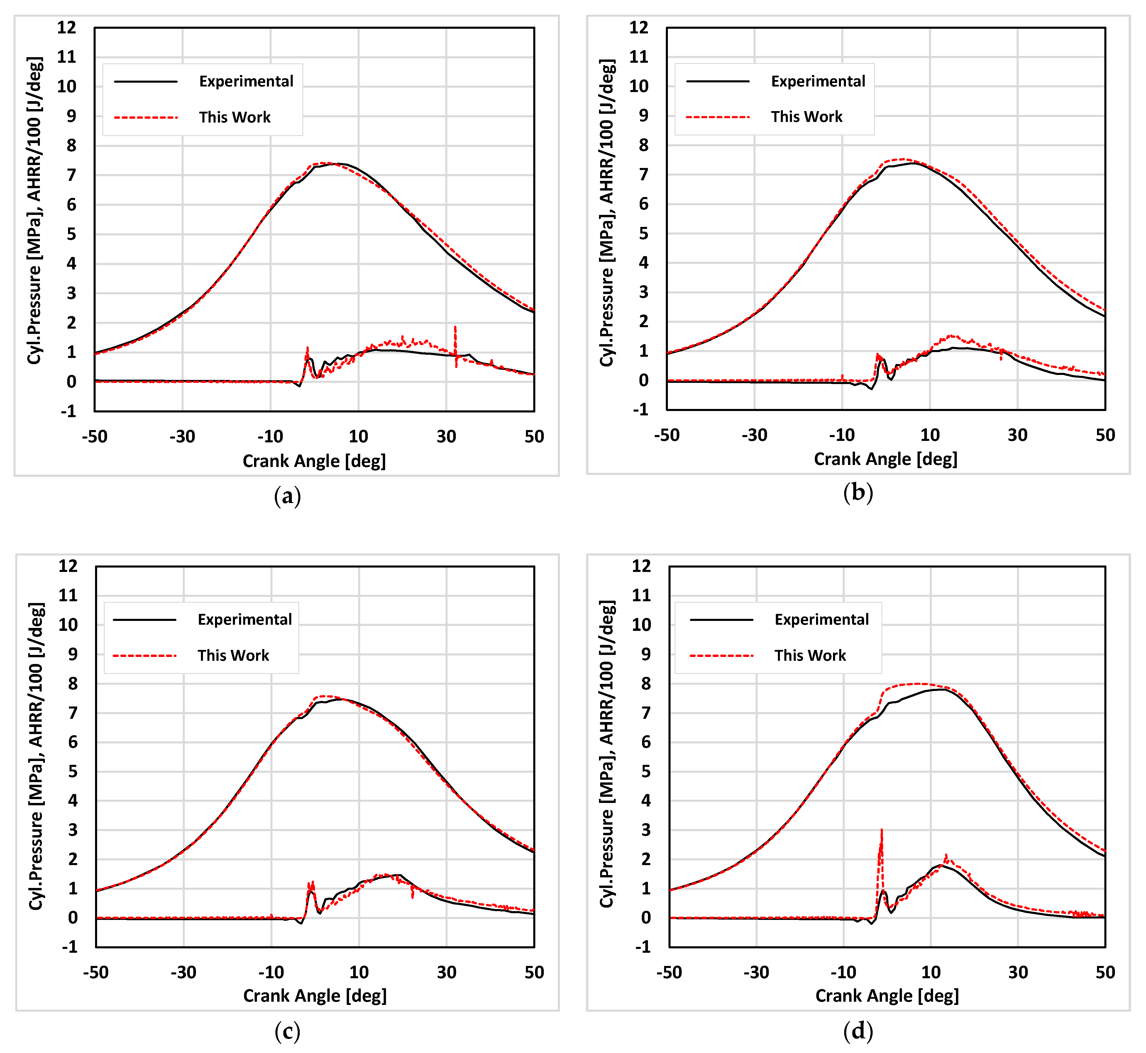
In Figure 2, the cylinder pressure and HRR, in this work and [23] are compared. It indicates the cylinder pressure and HRR over the mentioned range of syngas substitution quantities as well. The absolute errors in the cylinder peak pressure are 0.02, 0.14, 0.11 and 0.20 MPa while errors in the relevant crank angle of those peak points are 3.86, 2.66, 4.09 and 6.72 CA for the cases (a) to (d) respectively.
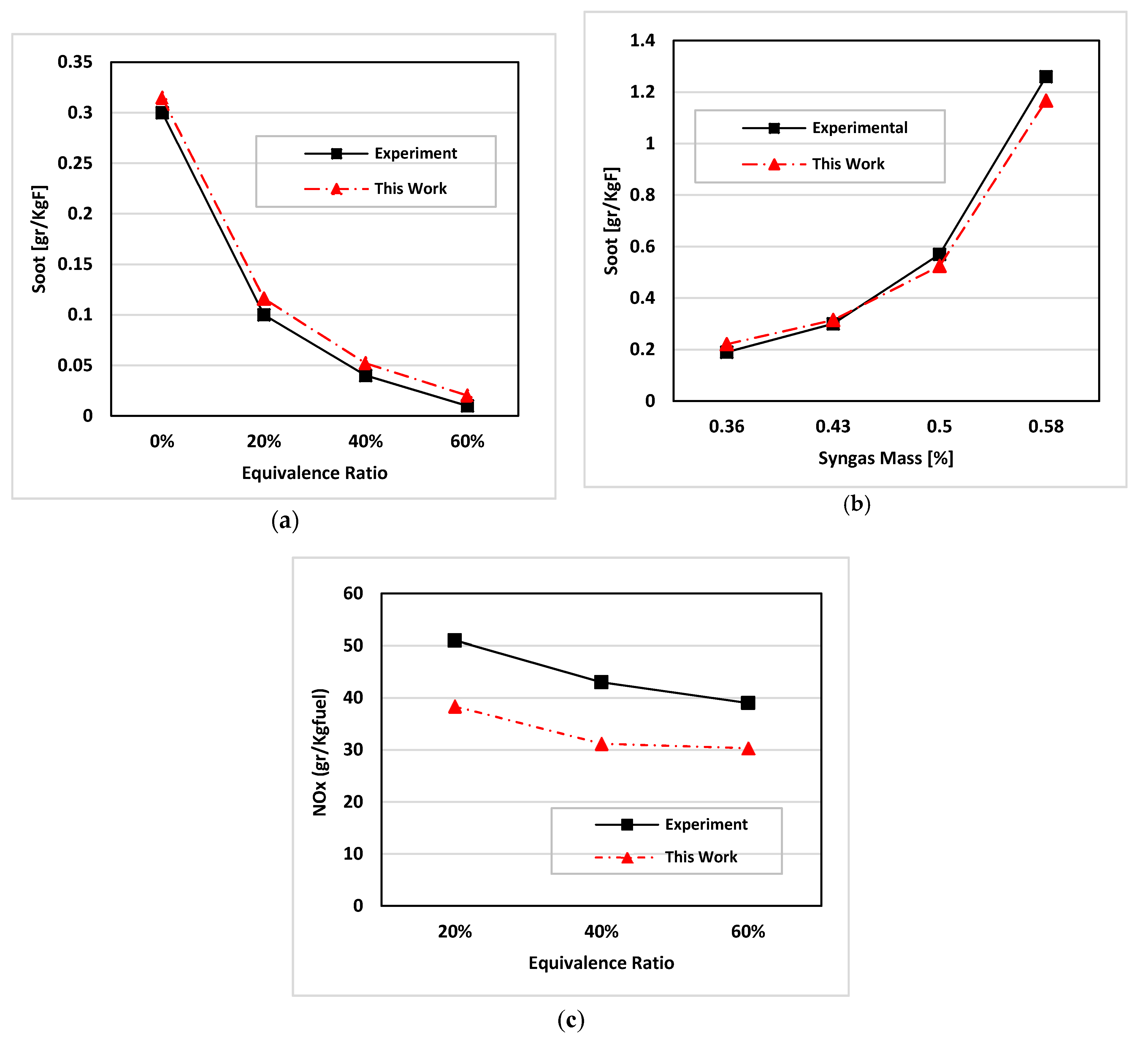
The emission results are also validated with the ones in Ref. [23] as shown in Figure 3. Even though the magnitude of NOX is accompanied with errors more than soot does, this model has the capability to capture the trends in NOX emissions. According to these results, the simulation is quite accurately done and the model may capture the cylinder pressure and HRR of both CDC and diesel-syngas RCCI operations exceptionally well over a wide equivalence ratios and syngas substitution ranges.
4. Results and Discussion
It has been shown that in recently patented RCCI engines, the combustion mode could be efficiently controlled by the reactivity gradient which is due to the blending of fuels with low and high reactivity, in the intake port and into the cylinder through the injector respectively [43,44,45]. Actual Syngas mixtures as well as a mixture of H2 and CO seem to be a promising candidate for application as the low reactivity fuel in RCCI engines. Thus, in this section, the same tests similar to those in validation part have been conducted with three different types of syngas mixtures obtained through gasification processes [46,47]. These fuels and their compositions selected for comparison with the simulated syngas which is consist of only H2 and CO are listed in Table 4. The engine operating conditions are the same as the validation case in Table 3. For all cases, a premixed substitution ratio sweep at constant fuel energy is utilized to investigate the effects on the engine.
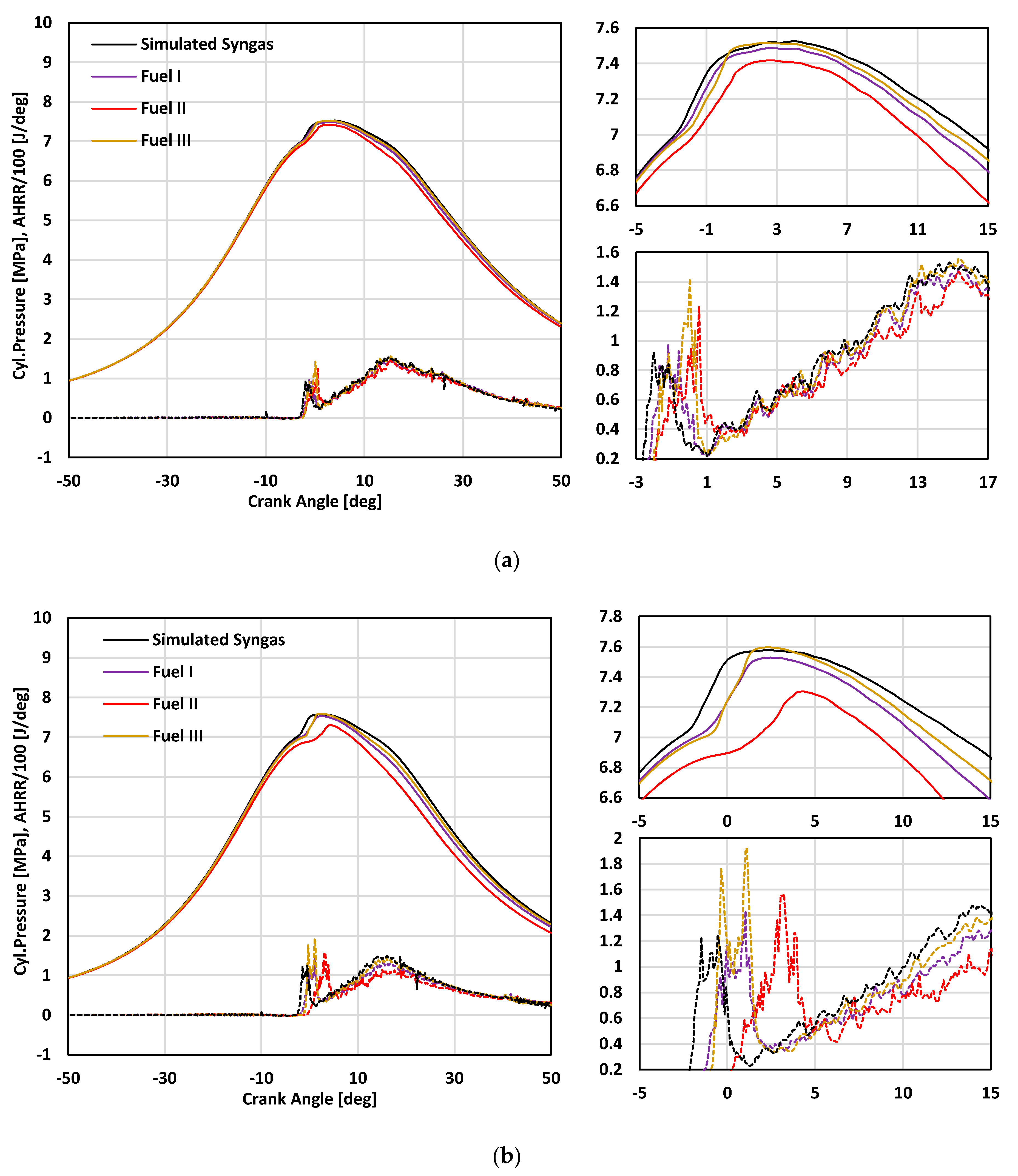
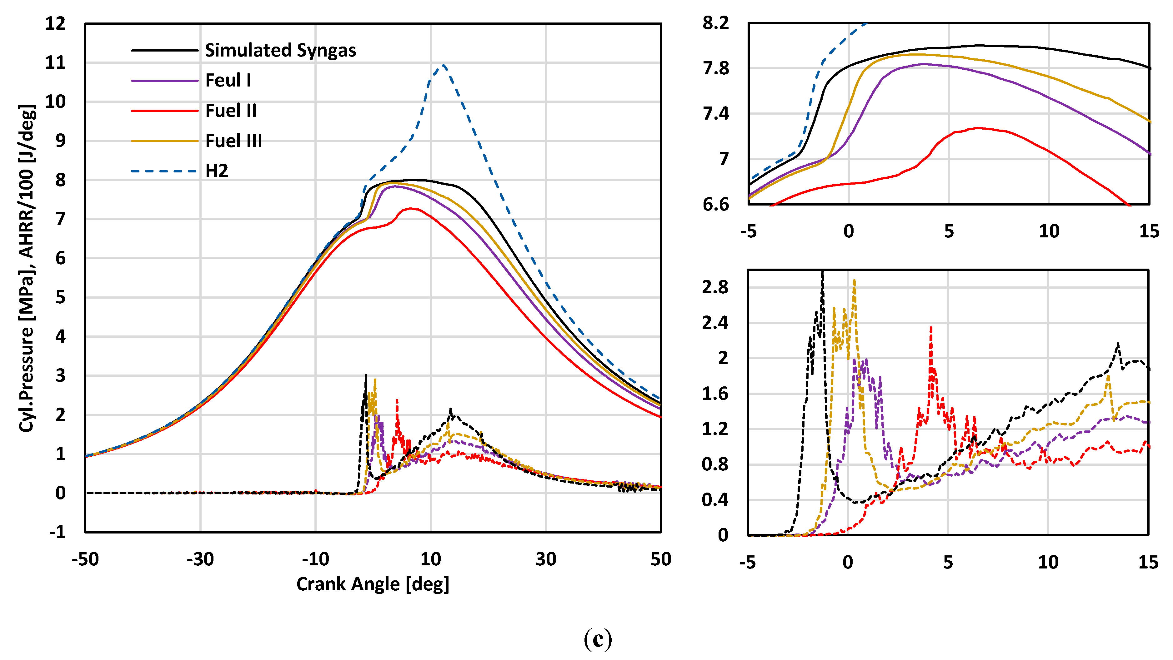
Previously, it was reported that CDC engines suffer from high soot and NOX pollutants, which are due to shorter ignition delay and very high temperatures associated with diesel. This is the reason for investigating addition syngas into the intake port by substituting part of input energy with different syngas compositions. Figure 4 illustrates the cylinder pressure and HRR over a range of substitution quantities for all fuel cases.
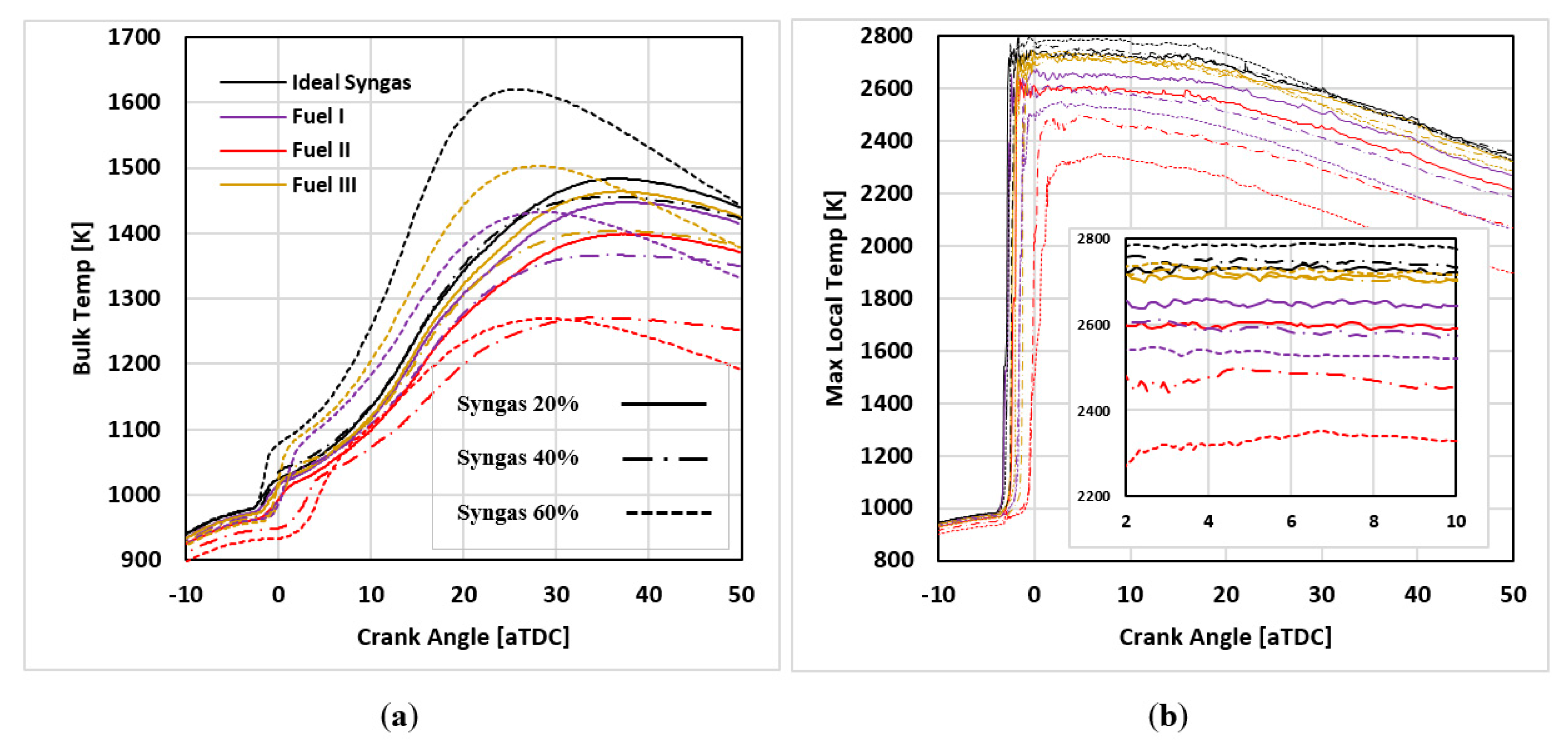
The ratios of H2 mass to the mass of other combustible species in syngas are 0.078, 0.065, 0.025 and 0.075 for simulated syngas, fuel I, II and III, respectively. An increase in this ratio results the peak pressure increased at the same substitution ratios as well. Therefore, the advanced CA50 (crank angle a 50% burn) higher hydrogen content cases can be attributed to both the higher speed of hydrogen flame and the higher total fuel reactivity. To make sure of this idea, an extra study was performed in 20% substitution ratio at the same engine conditions which its results is shown in Figure 4 by the dashed blue line. As can be seen, the higher hydrogen in fuel, results in the faster depletion of the fuel and the higher pressure rise rate. Since nitrogen occupies the majority of syngas volume in fuel I and II, the maximum pressure in these two cases for all scenarios are lower than the other two fuels. In the meantime, fuel II has the lowest hydrogen content among the other fuels and subsequently has the smoothest pressure. This has to be the consequence of the higher ignition delay which results in a longer transition from the combustion of diesel to ignition of syngas. Due to this matter fuel II has the lowest maximum bulk and local temperatures as shown in Figure 5, since enough time is available for heat transfer.
Figure 5 also indicates that as the syngas substitution rate increases from 20% to 40% and 40% to 60%, in the cases of the fuel I and II, the Temperatures decrease by 1.8 and 6.1% and by 1.9 and 5.7% respectively. This is just unlike the fuel III in which the increase of temperature has been evaluated up to 4%. These effects can be justified by the presence of nitrogen and lower hydrogen content. Even though by increasing the syngas substitution, hydrogen in simulated syngas and fuel III and both hydrogen and nitrogen in fuels I and II increase, however the effect of nitrogen is dominant in comparison with hydrogen. It might be noted that, in cases of fuels I and II, the engine may suffer from achieving a stable state at low loads using these fuels because self-ignition temperature could be too hard to reach due to their low pressure and temperature natures. Therefore, very low temperature and pressure cannot be always accounted as an advantage.
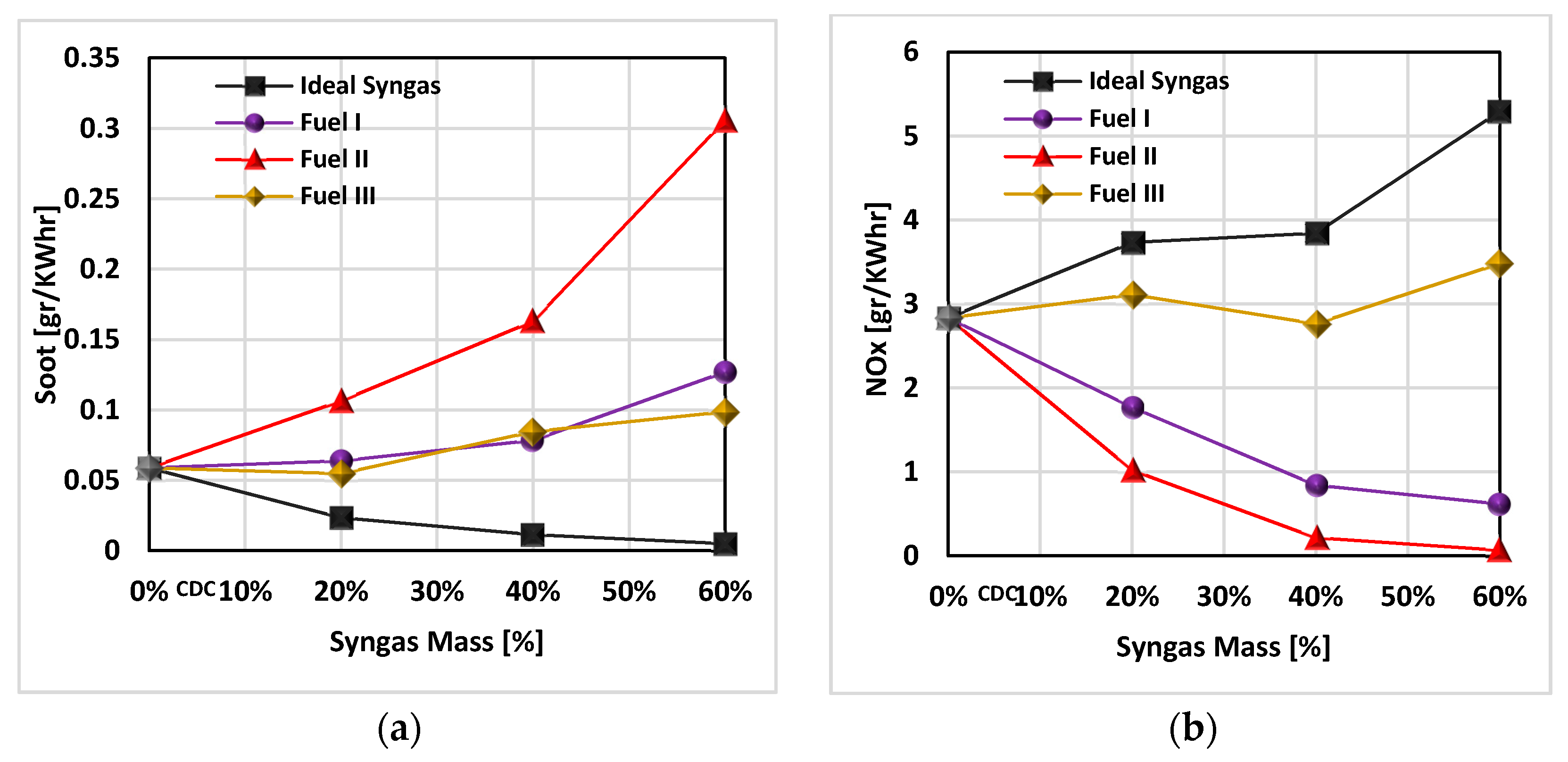
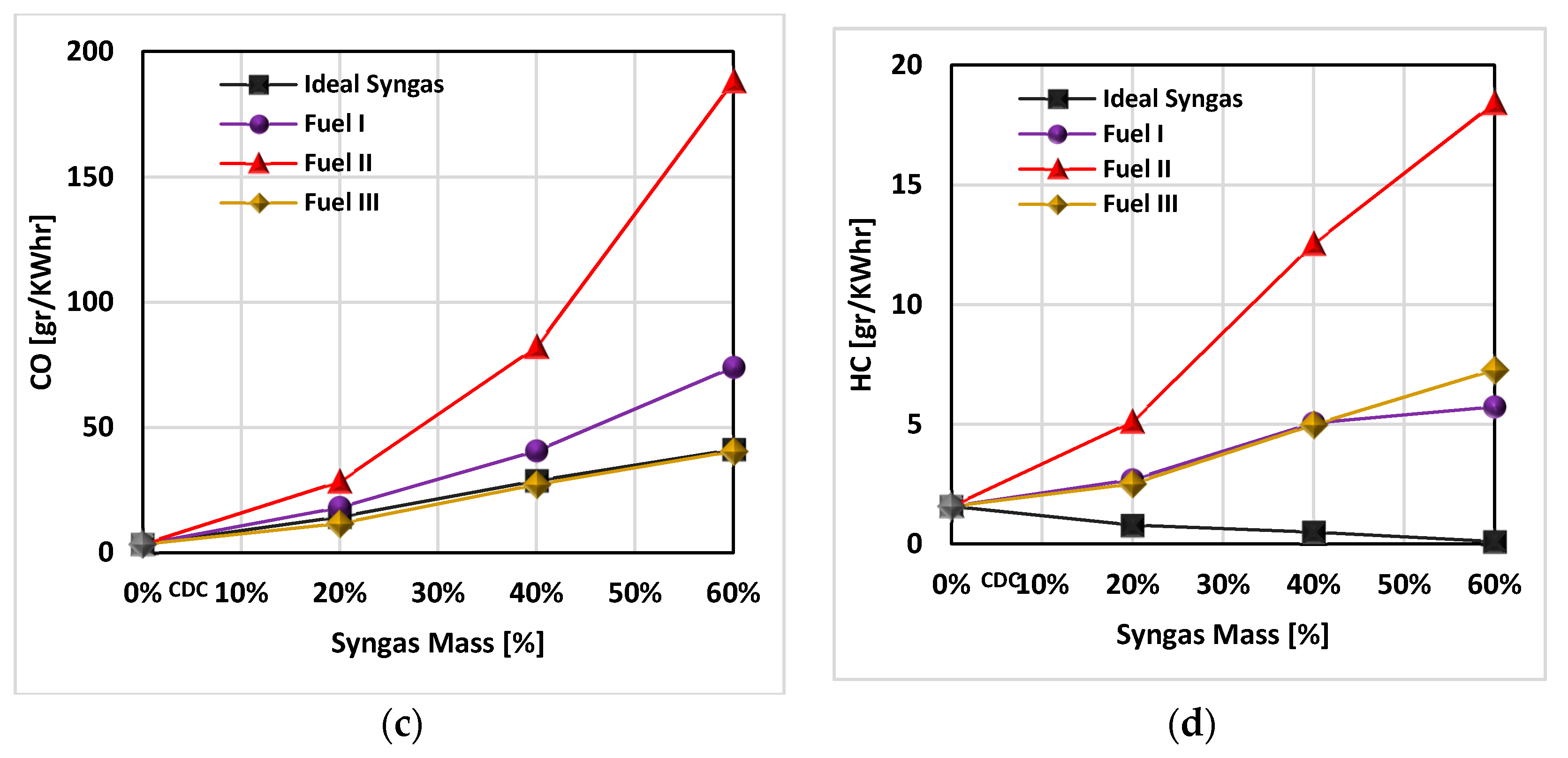
Figure 6 indicates the amount of four emissions for all scenarios. Specific emissions unit has been selected to show the amount of emissions. Compared to CDC, reduction of NOX by 78% and 97% in case scenario of 60% substitution of syngas, for fuels I and II in exchange for increasing by 21% and 85% for fuel III and simulated syngas prove the fact that with the decrease of hydrogen content and increase of nitrogen at constant fuel energy, at the expense of other emissions, NOX decreases. In this regard, NOX in Fuel II, adverse to the other pollutants (Co, UHC and soot) has the lowest amount than the other fuels. This conclusion is compatible with the previous results as well. Operating the engine with fuel II results in decreased stratification and by increasing the substitution ratio of this fuel, a steeper reduction in NOX is detected. To put it another way, reduced local equivalence, less flame temperature and retarded combustion phasing are the reasons which prevents the NOX emissions to be formed. Compared to the simulated one, all three types of actual syngas mixtures cause an increase in soot emission. This is due to the existence of other species in syngas like carbon dioxide and nitrogen which decrease the oxygen amount in premixed air. This lack of oxygen prevents the fuels from the complete burning and is the reason for lower volumetric efficiencies. In addition to these reasons, the role of other combustible species like CH4, C2H4, and C2H6 in soot formation shouldn’t be ignored. Since CO traps in crevice regions where the flames usually do not reach, increase of this emission with the increase of syngas substitution in all four fuel cases, was expected. That’s why compared to CDC, the amount of carbon monoxide increases by 11.4, 21.4, 56 and 11.2% in 60% syngas substitution for simulated syngas, fuel I, II and III respectively.
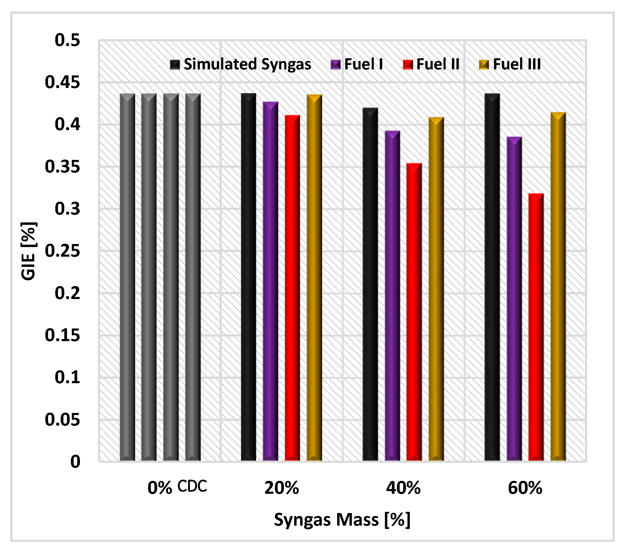
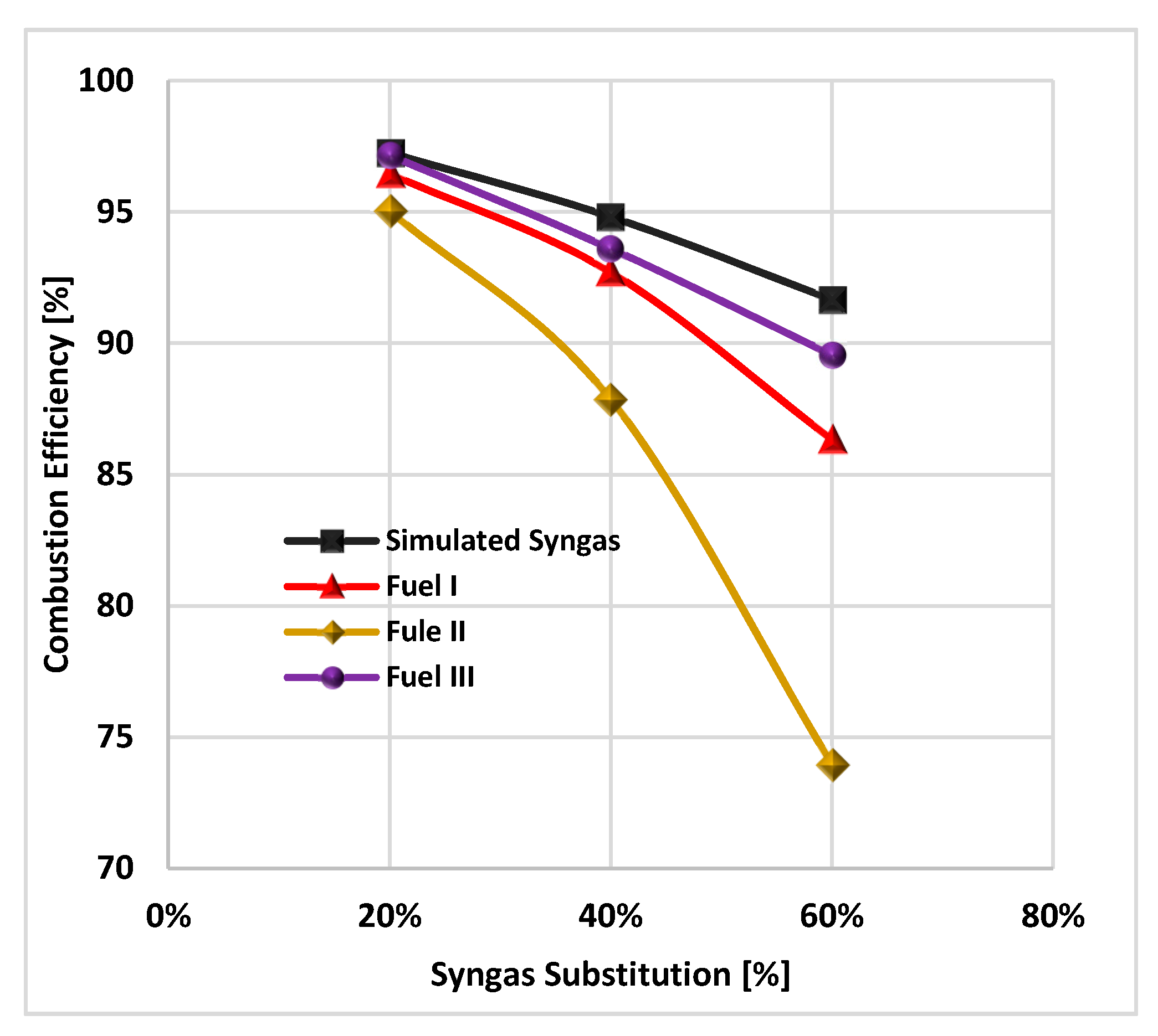
Figure 7 and Figure 8 show the gross indicated efficiency (GIE) and combustion efficiency of each case at various scenarios, respectively. GIE and combustion efficiency can be calculated as:
Notwithstanding the higher heat transfer of simulated syngas due to its high temperature feature, lower volumetric efficiencies and also lack of oxygen in case of fuels I to III compared to the simulated syngas cause the lower work, lower GIE and consequently lower combustion efficiency. In this regard fuel II with 27.1% reduction in compared with CDC has the maximum reduction in GIE. Undoubtedly, the reduced work cannot be outweighed by increased syngas quantity which reduced heat transfer amount. Due to the higher flame speed and temperature, increasing H2 fraction has a congruent effect on combustion efficiency. These effects force the flame to ignite the fuels near the crevice regions due probably to the higher reactivity of the premixed charge and shorter quenching distance of H2. Notice that GIE and combustion efficiency decrease with increasing syngas portion in the engine at constant energy. That is because of incomplete combustion which has been previously elaborated.
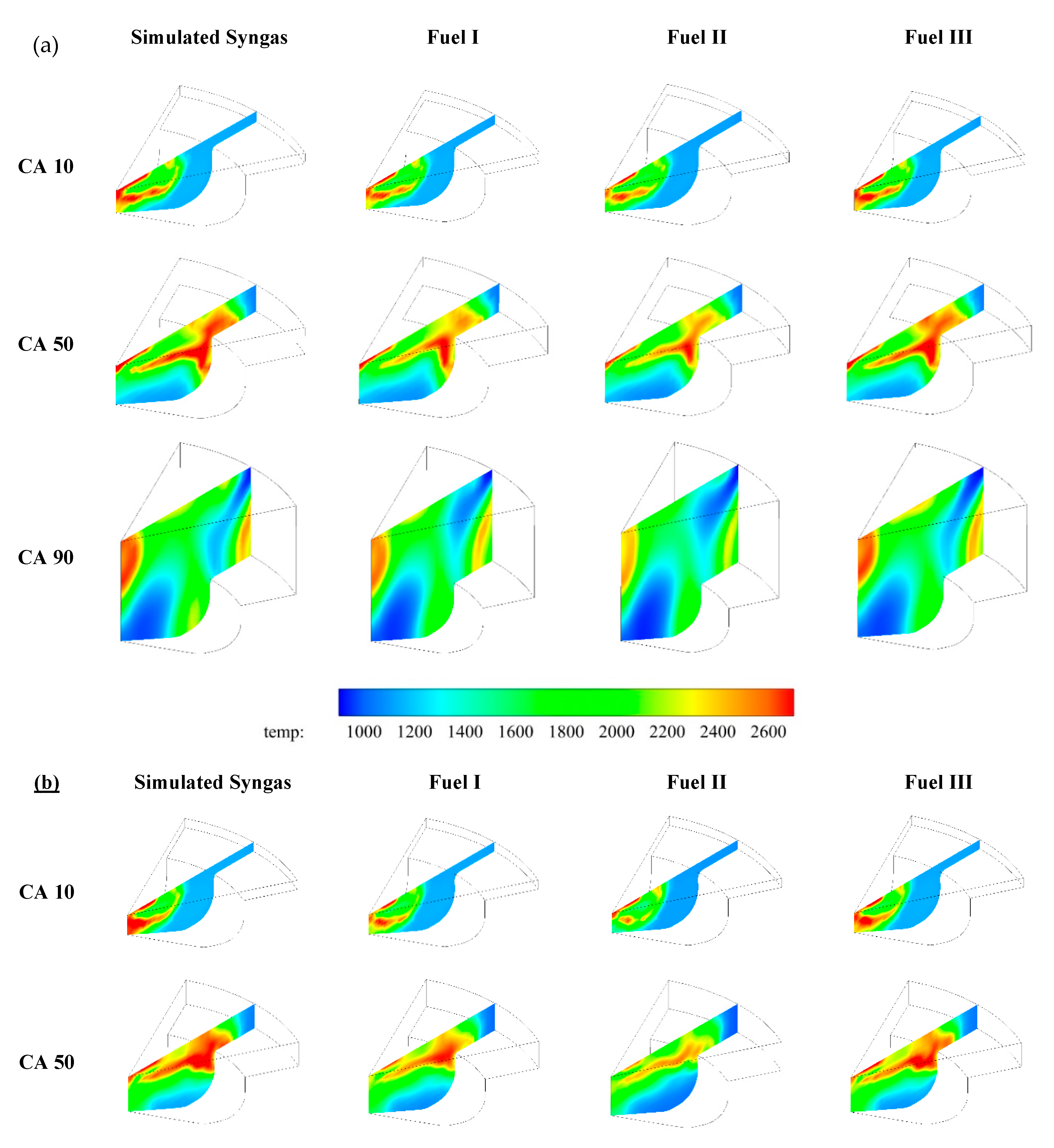
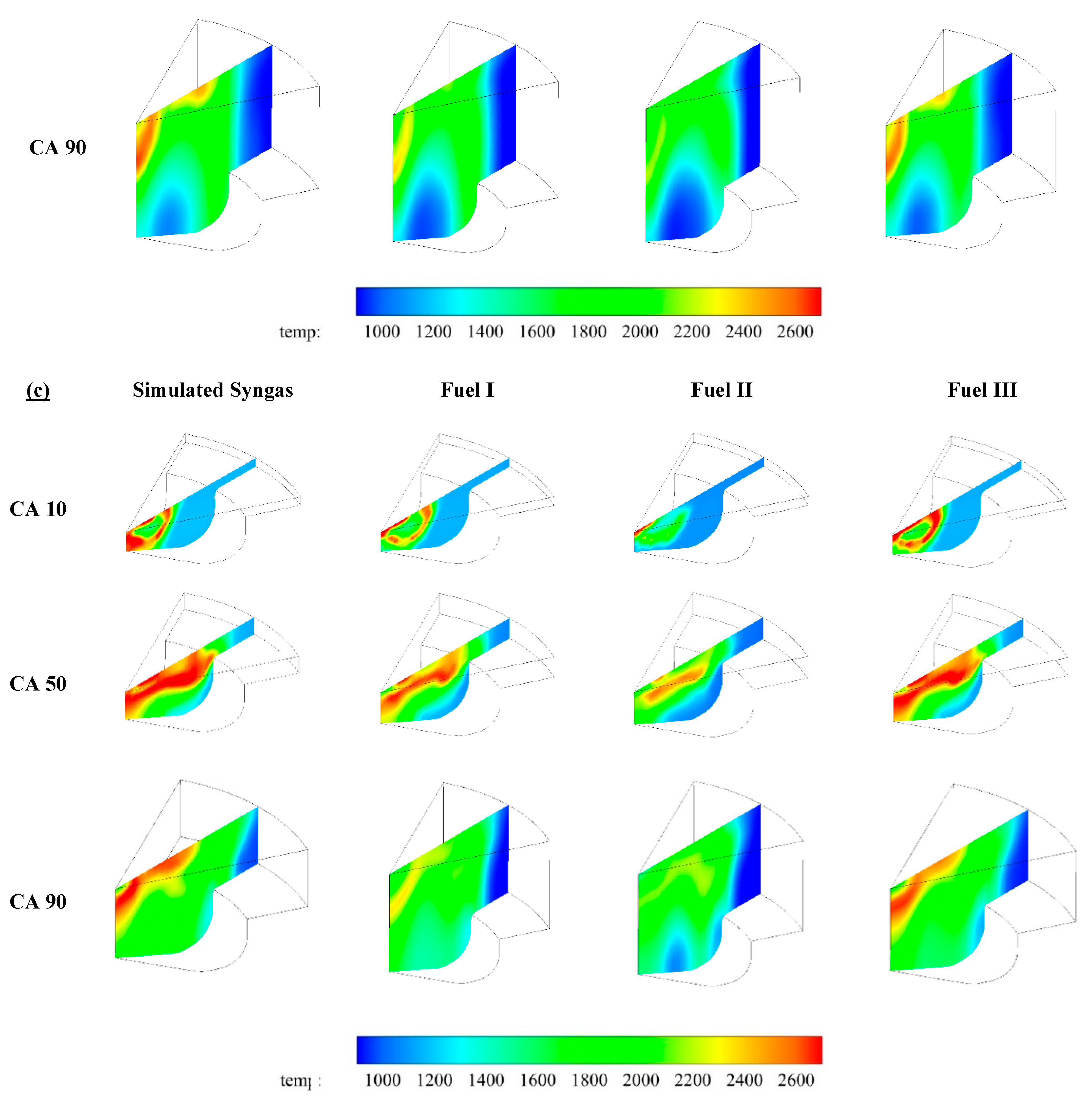
Table 5 displays CA10, CA50, and CA90 of all cases over the syngas quantities sweep. It should be noted that, for a specific premixed ratio, simulated syngas has an earlier combustion phasing than actual ones. Contours in cut planes in Figure 9 illustrates the local temperatures inside the cylinder at CA10, CA50, and CA90 for all three scenarios. According to these contours, fuel II and fuel III have the lowest and the highest temperatures respectively among the actual syngas mixtures. Due to the high flame temperature and burning rate of H2 which results in efficient and complete combustion, the temperature would be somewhat higher in the simulated syngas case. In all scenarios, more homogenous combustion can be detected in compare with CDC.
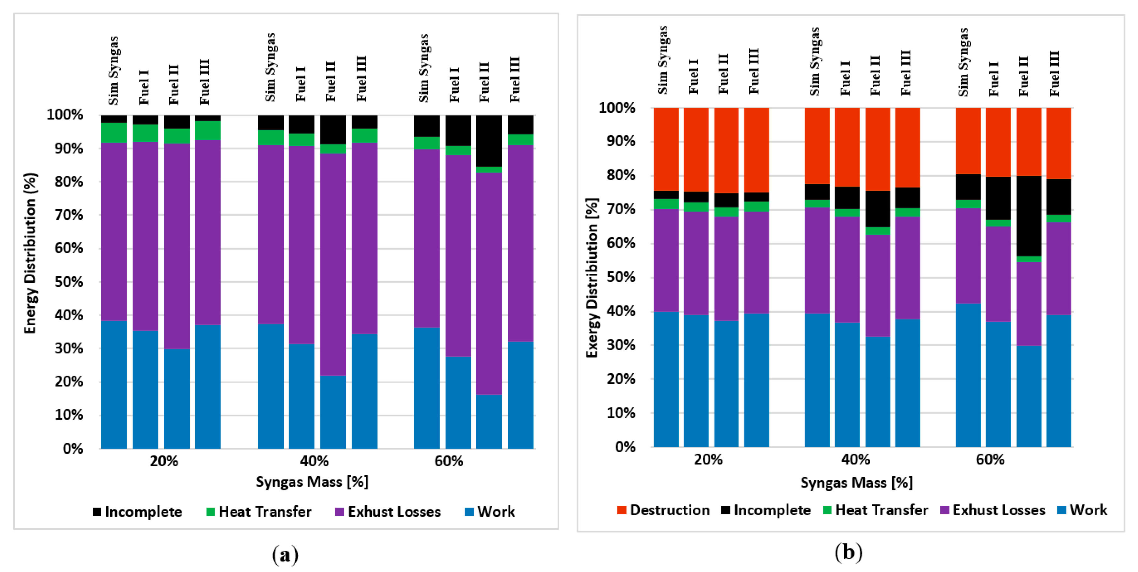
In order to better investigating the differences among these four cases (fuels), energy and exergy analysis obtained from the first and second law principles were conducted. Through this concept exergy destruction as an extra important term which restricts the maximum achievable output power has been calculated. The energy and exergy distributions of the four fuels at various syngas masses are shown in Figure 10. The total energy can be categorized into four parts. Output power or work, transferred heat, energy losses through exhaust gases and incomplete combustion. At the same classification viewpoint, total exergy, divided into five categories. Output power or exergy of useful work, exergy destruction, exergy of heat transfer, exergy transfer through exhaust gases and incomplete combustion. The last three terms can be categorized as one called exergy of transfer.
As can be observed, fuel II has the most energy and exergy losses as for incomplete combustion among all fuels. This can be justified due to lower temperature which prevents burning of parts of the fuel. The energy and exergy of the transferred heat through walls, cylinder head and piston surface which are the boundaries of the combustion chamber, are minimum for fuel II compared to the others due to the same reason. It is worthy to mention that the low amount of heat transfer and the high amount of exhaust energy losses is due mostly to the closed system analyses assumption. As shown in Figure 10, the exhaust losses of simulated syngas are much lower than of actual ones. This implies that simulated syngas has the potential of giving much more mechanical energy in shape of work instead of being rejected by the exhaust gases. In this point of view, fuel III has the nearest behavior to syngas and fuel II has the less capability of work production.
By superficially comparing the two figures (Figure 10a,b), it is seen that all the fractions of exergy compared to their corresponding percentage in energy categories, are quantitively less. This is due inherently to the difference between energy and exergy of a fuel. The fact is the exergy of one fuel is the intrinsic chemical energy of it, which is generally larger than its LHV [48]. Above all, the degradation of each energy category during the process of conversion leads to lower fractions in the second law of thermodynamics [49]. Despite of this, the overall variation trends according to the first and second laws are compatible.
As mentioned before, among the four fuel cases, the exergy of work of simulated syngas is the highest in all scenarios. By contrast, fuel II has the lowest output work which is shown in Figure 10 as well. Furthermore, the exergy destruction of simulated syngas, fuel I and fuel III are less than that of fuel II, which means more useful work can be extracted from those three. It is proven that most of the exergy destruct in the combustion process and for this reason a higher combustion temperature will help the exergy to be more destructed [50,51]. Thus, all the fuels have less exergy destruction in 60 percent case. It can be also perceived that the differences of exergy destruction between the four fuels reduce as the portion of syngas gets higher, while the advantages of RCCI combustion over CDC remain.
5. Conclusions
A numerical analysis has been performed to assess the effects of syngas (produced by gasification) compared to simulated syngas (contains carbon monoxide and hydrogen) on the engine exhaust emissions and performance of a syngas-diesel RCCI engine while the energy amount per cycle is constant. The following major conclusions may be stated:
- Peak pressure, PRR, bulk, and max local temperatures increase significantly with increasing the ratios of H2 mass to the mass of other combustible species in syngas. Shortened ignition delay, advanced CA50, sharper HRR, more NOX while less soot, CO and UHC production are obtained for this reason. Therefor hydrogen-rich mixture is the best choice for boosting combustion efficiency.
- Presence of N2 in syngas composition at all syngas substitution ratios force the temperatures to be decreased. Thus, less NOX is achieved by the fuels with nitrogen in their composition (Fuels I and II).
- In terms of exergy view, Fuel I and III resemble simulated syngas. Less increase in exergy of incomplete combustion due to their combustion efficiencies are obtained by the increase of syngas substitution ratio.
- It is expected that the engine may suffer from achieving a stable state at low loads using fuel II due to very low H2 percentage in the syngas.
- The results indicate that compared to the other methods, the syngas produced by the first way of gasification (fuel I), could be a promising candidate as the low reactivity fuel in RCCI engines. NOX emissions decline as the ratio of syngas increases while soot and UHC emissions remained relatively constant. On the other hand, the exergy of exhaust losses is relatively close to the simulated syngas.
Author Contributions
Conceptualization, N.K., and A.P.; software, N.K.; validation, N.K., A.P. and A.S.M. investigation, N.K. and A.S.M.; resources, M.Y. and G.F.d.l.F.; data curation, N.K., A.S.M., and M.Y.; writing—original draft preparation, N.K., M.Y., A.S.M., and A.P.; writing—review and editing, M.Y. and A.P.; supervision, M.Y., A.S.M., and G.F.d.l.F. All authors have read and agreed to the published version of the manuscript.
Funding
The research is supported by a grant from University of Bonab (contract number: 9806).
Acknowledgments
The authors would like to thank Chuahy from Oak Ridge National Laboratory for providing the data for simulation and research office of University of Hertfordshire for the support. The authors also thank Convergent Science Inc. for providing a free version of their CONVERGE package for academic purposes.
Conflicts of Interest
The authors declare no conflict of interest.
Nomenclature
| ATDC | After Top Dead Center | IC | Internal Combustion |
| BTDC | Before Top Dead Center | IDT | Ignition Delay Time |
| CA10 | Crank Angle Of 10% Mass Fraction Burned | IMEP | Indicated Mean Effective Pressure |
| CA50 | Crank Angle Of 50% Mass Fraction Burned | IVC | Inlet Valve Close |
| CA90 | Crank Angle Of 90% Mass Fraction Burned | IVO | Inlet Valve Open |
| CDC | Conventional Diesel Combustion | LHV | Lower Heating Value |
| CFD | Computational Fluid Dynamics | LTC | Low Temperature Combustion |
| CI | Compression Ignition | PCCI | Premixed Charge Compression Ignition |
| EVC | Exhaust Valve Close | PRR | Pressure Rise Rate |
| EVO | Exhaust Valve Open | RCCI | Reactivity Controlled Compression Ignition |
| GIE | Gross Indicated Efficiency | RI | Ringing Intensity |
| HCCI | Homogeneous Charge Compression Ignition | UHC | Unburned Hydrocarbon |
| HRR | Heat Release Rate |
References
- Walker, N.R.; Chuahy, F.D.F.; Reitz, R.D. Comparison of diesel pilot ignition (DPI) and reactivity controlled compression ignition (RCCI) in a heavy-duty engine. In Proceedings of the ASME 2015 Internal Combustion Engine Division Fall Technical Conference, Houston, TX, USA, 8–11 November 2015. [Google Scholar]
- Wissink, M.; Reitz, R.D. Direct dual fuel stratification, a path to combine the benefits of RCCI and PPC. SAE Int. J. Engines 2015, 8, 878–889. [Google Scholar] [CrossRef]
- Noehre, C.; Andersson, M.; Johansson, B.; Hultqvist, A. Characterization of Partially Premixed Combustion; SAE Technical Paper: Warrendale, PA, USA, 2006. [Google Scholar]
- Kalghatgi, G.T.; Risberg, P.; Ångström, H.E. Advantages of Fuels with High Resistance to Auto-Ignition in Late-Injection, Low-Temperature, Compression Ignition Combustion; SAE Technical Paper: Warrendale, PA, USA, 2006. [Google Scholar]
- Sellnau, M.C.; Sinnamon, J.; Hoyer, K.; Husted, H. Full-time gasoline direct-injection compression ignition (GDCI) for high efficiency and low NOX and PM. SAE Int. J. Engines 2012, 5, 300–314. [Google Scholar] [CrossRef]
- Kalghatgi, G.T.; Risberg, P.; Ångström, H.E. Partially Pre-Mixed Auto-Ignition of Gasoline to Attain Low Smoke and Low NOX at High Load in A Compression Ignition Engine and Comparison with a Diesel Fuel; SAE Technical Paper: Warrendale, PA, USA, 2007. [Google Scholar]
- Kokjohn, S.L.; Reitz, R.D. An investigation of charge preparation strategies for controlled PPCI combustion using a variable pressure injection system. Int. J. Eng. Res. 2010, 11, 257–282. [Google Scholar] [CrossRef]
- Lu, X.; Han, D.; Huang, Z. Fuel design and management for the control of advanced compression-ignition combustion modes. Prog. Energy Combust. Sci. 2011, 37, 741–783. [Google Scholar] [CrossRef]
- Paykani, A.; Kakaee, A.H.; Rahnama, P.; Reitz, R.D. Progress and recent trends in reactivity-controlled compression ignition engines. Int. J. Engine Res. 2016, 17, 481–524. [Google Scholar] [CrossRef]
- Kokjohn, S.; Hanson, R.; Splitter, D.; Kaddatz, J.; Reitz, R. Fuel reactivity controlled compression ignition (RCCI) combustion in light-and heavy-duty engines. SAE Int. J. Engines 2011, 4, 360–374. [Google Scholar] [CrossRef]
- Kokjohn, S.L.; Hanson, R.M.; Splitter, D.A.; Reitz, R.D. Fuel reactivity controlled compression ignition (RCCI): A pathway to controlled high-efficiency clean combustion. Int. J. Engine Res. 2011, 12, 209–226. [Google Scholar] [CrossRef]
- Walker, N.R.; Wissink, M.L.; DelVescovo, D.A.; Reitz, R.D. Natural gas for high load dual-fuel reactivity controlled compression ignition in heavy-duty engines. J. Energy Resour. Technol. 2015, 137, 42202. [Google Scholar] [CrossRef]
- Nieman, D.E.; Dempsey, A.B.; Reitz, R.D. Heavy-duty RCCI operation using natural gas and diesel. SAE Int. J. Engines 2012, 5, 270–285. [Google Scholar] [CrossRef]
- Dempsey, A.B.; Adhikary, B.D.; Viswanathan, S.; Reitz, R.D. Reactivity controlled compression ignition using premixed hydrated ethanol and direct injection diesel. J. Eng. Gas Turbines Power 2012, 134, 82806. [Google Scholar] [CrossRef]
- Benajes, J.; Molina, S.; García, A.; Monsalve-Serrano, J. Effects of direct injection timing and blending ratio on RCCI combustion with different low reactivity fuels. Energy Convers. Manag. 2015, 99, 193–209. [Google Scholar] [CrossRef]
- Li, J.; Yang, W.; Zhou, D. Review on the management of RCCI engines. Renew. Sustain. Energy Rev. 2017, 69, 65–79. [Google Scholar] [CrossRef]
- Sahoo, B.B.; Sahoo, N.; Saha, U.K. Effect of H2: CO ratio in syngas on the performance of a dual fuel diesel engine operation. Appl. Therm. Eng. 2012, 49, 139–146. [Google Scholar] [CrossRef]
- Bika, A.S.; Franklin, L.; Kittelson, D. Cycle Efficiency and Gaseous Emissions from A Diesel Engine Assisted with Varying Proportions of Hydrogen and Carbon Monoxide (Synthesis Gas); SAE Technical Paper: Warrendale, PA, USA, 2011. [Google Scholar]
- Rahnama, P.; Paykani, A.; Bordbar, V.; Reitz, R.D. A numerical study of the effects of reformer gas composition on the combustion and emission characteristics of a natural gas/diesel RCCI engine enriched with reformer gas. Fuel 2017, 209, 742–753. [Google Scholar] [CrossRef]
- Rahnama, P.; Paykani, A.; Reitz, R.D. A numerical study of the effects of using hydrogen, reformer gas and nitrogen on combustion, emissions and load limits of a heavy duty natural gas/diesel RCCI engine. Appl. Energy 2017, 193, 182–198. [Google Scholar] [CrossRef]
- Chuahy, F.D.F.; Kokjohn, S. System and Second Law Analysis of the Effects of Reformed Fuel Composition in “Single” Fuel RCCI Combustion. SAE Int. J. Engines 2018, 11, 861–878. [Google Scholar] [CrossRef]
- Chuahy, F.D.F.; Kokjohn, S.L. Effects of reformed fuel composition in “single” fuel reactivity controlled compression ignition combustion. Appl. Energy 2017, 208, 1–11. [Google Scholar] [CrossRef]
- Chuahy, F.D.F.; Kokjohn, S.L. High efficiency dual-fuel combustion through thermochemical recovery and diesel reforming. Appl. Energy 2017, 195, 503–522. [Google Scholar] [CrossRef] [Green Version]
- Xu, Z.; Jia, M.; Li, Y.; Chang, Y.; Xu, G.; Xu, L.; Lu, X. Computational optimization of fuel supply, syngas composition, and intake conditions for a syngas/diesel RCCI engine. Fuel 2018, 234, 120–134. [Google Scholar] [CrossRef]
- Rutland, C.J. Modeling Investigation of Different Methods to Suppress Engine Knock on a Small Spark Ignition Engine. J. Eng. Gas Turbines Power. 2016, 137, 61506. [Google Scholar]
- Costa, M.; Villetta, M.L.; Massarotti, N.; Piazzullo, D.; Rocco, V. Numerical analysis of a compression ignition engine powered in the dual-fuel mode with syngas and biodiesel. Energy 2017, 137, 969–979. [Google Scholar] [CrossRef]
- Richards, K.J.; Senecal, P.K.; Pomraning, E. CONVERGE manual (Version 2.3); Convergent Science Inc.: Madison, WI, USA, 2016. [Google Scholar]
- REITZ, R. Modeling atomization processes in high-pressure vaporizing sprays. At. Spray Technol. 1987, 3, 309–337. [Google Scholar]
- Amsden, A.A.; O’Rourke, P.J.; Butler, T.D. KIVA-II: A Computer Program for Chemically Reactive Flows with Sprays; Los Alamos National Laboratory: Santa Fe, NM, USA, 1989.
- Han, Z.; Reitz, R.D. Turbulence modeling of internal combustion engines using RNG κ-ε models. Combust. Sci. Technol. 1995, 106, 267–295. [Google Scholar] [CrossRef]
- Schmidt, D.P.; Rutland, C.J. A new droplet collision algorithm. J. Comput. Phys. 2000, 164, 62–80. [Google Scholar] [CrossRef]
- O’Rourke, P.J.; Amsden, A.A. The TAB Method for Numerical Calculation of Spray Droplet Breakup; SAE Technical Paper: Warrendale, PA, USA, 1987. [Google Scholar]
- O’Rourke, P.J.; Amsden, A.A. A spray/wall interaction submodel for the KIVA-3 wall film model. SAE Trans. 2000, 109, 281–298. [Google Scholar]
- Heywood, J.B. Internal Combustion Engine Fundamentals; McGraw-Hill Education: New York, NY, USA, 2018. [Google Scholar]
- Hiroyasu, H.; Kadota, T. Models for combustion and formation of nitric oxide and soot in direct injection diesel engines. SAE Trans. 1976, 85, 513–526. [Google Scholar]
- Senecal, P.K.; Pomraning, E.; Richards, K.J.; Briggs, T.E.; Choi, C.Y.; McDavid, R.M.; Patterson, M.A. Multi-dimensional modeling of direct-injection diesel spray liquid length and flame lift-off length using CFD and parallel detailed chemistry. SAE Trans. 2003, 112, 1331–1351. [Google Scholar]
- Ren, S.; Kokjohn, S.L.; Wang, Z.; Liu, H.; Wang, B.; Wang, J. A multi-component wide distillation fuel (covering gasoline, jet fuel and diesel fuel) mechanism for combustion and PAH prediction. Fuel 2017, 208, 447–468. [Google Scholar] [CrossRef]
- Kéromnès, A.; Metcalfe, W.K.; Heufer, K.A.; Donohoe, N.; Das, A.K.; Sung, C.J.; Herzler, J.; Naumann, C.; Griebel, P.; Mathieu, O. An experimental and detailed chemical kinetic modeling study of hydrogen and syngas mixture oxidation at elevated pressures. Combust. Flame 2013, 160, 995–1011. [Google Scholar] [CrossRef] [Green Version]
- Raju, M.; Wang, M.; Dai, M.; Piggott, W.; Flowers, D. Acceleration of Detailed Chemical Kinetics Using Multi-Zone Modeling for CFD in Internal Combustion Engine Simulations; SAE Technical Paper: Warrendale, PA, USA, 2012. [Google Scholar]
- Cengel, Y.A.; Boles, M.A. Thermodynamics: An engineering approach. Sea 2002, 1000, 8862. [Google Scholar]
- Ferguson, C.R.; Kirkpatrick, A.T. Internal Combustion Engines: Applied Thermosciences; Wiley-Blackwell: Hoboken, NJ, USA, 1986. [Google Scholar]
- Javaheri, A.; Esfahanian, V.; Salavati-Zadeh, A.; Darzi, M. Energetic and exergetic analyses of a variable compression ratio spark ignition gas engine. Energy Convers. Manag. 2014, 88, 739–748. [Google Scholar] [CrossRef]
- Wang, Y.; Yao, M.; Li, T.; Zhang, W.; Zheng, Z. A parametric study for enabling reactivity controlled compression ignition (RCCI) operation in diesel engines at various engine loads. Appl. Energy 2016, 175, 389–402. [Google Scholar] [CrossRef]
- Srinivas, T.; Gupta, A.V.S.S.K.S.; Reddy, B.V. Thermodynamic Equilibrium Model and Exergy Analysis of a Biomass Gasifier. J. Energy Resour. Technol. 2009, 131, 31801. [Google Scholar] [CrossRef]
- Reitz, R.D. Directions in internal combustion engine research. Combust. Flame 2013, 1, 1–8. [Google Scholar] [CrossRef]
- Zhang, J.; Lora, E.E.S.; de Mello e Pinto, L.R.; Corrêa, P.S.P.; Andrade, R.V.; Ratner, A. Experimental study on applying biomass-derived syngas in a microturbine. Appl. Therm. Eng. 2018, 146, 328–337. [Google Scholar]
- Costa, M.; Massarotti, N.; Vanoli, L.; Cirillo, D.; La Villetta, M. Performance analysis of a biomass powered micro-cogeneration system based on gasification and syngas conversion in a reciprocating engine. Energy Convers. Manag. 2018, 175, 33–48. [Google Scholar]
- Szybist, J.P.; Chakravathy, K.; Daw, C.S. Analysis of the impact of selected fuel thermochemical properties on internal combustion engine efficiency. Energy Fuels 2012, 26, 2798–2810. [Google Scholar] [CrossRef]
- Caton, J.A. A review of investigations using the second law of thermodynamics to study internal-combustion engines. SAE Trans. 2000, 1252–1266. [Google Scholar]
- Rakopoulos, C.D.; Giakoumis, E.G. Second-law analyses applied to internal combustion engines operation. Prog. Energy Combust. Sci. 2006, 32, 2–47. [Google Scholar] [CrossRef]
- Caton, J.A. Combustion phasing for maximum efficiency for conventional and high efficiency engines. Energy Convers. Manag. 2014, 77, 564–576. [Google Scholar] [CrossRef]
Figure 1.
Geometry and grid of the combustion chamber sector.

Figure 2.
Validation for engine operation (a) phi = 0.43 without syngas; (b) Syngas = 20%; (c) Syngas = 40%; (d) Syngas = 60% [23].
Figure 2.
Validation for engine operation (a) phi = 0.43 without syngas; (b) Syngas = 20%; (c) Syngas = 40%; (d) Syngas = 60% [23].

Figure 3.
Validation for emissions between experiments [23] and simulations (a) Soot in CDC; (b) Soot in Diesel-Syngas; (c) NOX in Diesel-Syngas.
Figure 3.
Validation for emissions between experiments [23] and simulations (a) Soot in CDC; (b) Soot in Diesel-Syngas; (c) NOX in Diesel-Syngas.

Figure 4.
Cylinder pressure and HRR for RCCI engine fueled with diesel and different syngas mixtures with varying syngas substitution ratios in constant energy per cycle for syngas, (a) 20%; (b) 40%; (c) 60%.
Figure 4.
Cylinder pressure and HRR for RCCI engine fueled with diesel and different syngas mixtures with varying syngas substitution ratios in constant energy per cycle for syngas, (a) 20%; (b) 40%; (c) 60%.


Figure 5.
Temperature comparison between fuels with varying syngas substitution ratios, (a) Cylinder Bulk Temperature; (b) Maximum Local Temperature.
Figure 5.
Temperature comparison between fuels with varying syngas substitution ratios, (a) Cylinder Bulk Temperature; (b) Maximum Local Temperature.

Figure 6.
Trend of emissions for the studied RCCI engine fed by various fuel mixture against different syngas substitution ratios (a) Soot; (b) NOX; (c) CO; (d) UHC.
Figure 6.
Trend of emissions for the studied RCCI engine fed by various fuel mixture against different syngas substitution ratios (a) Soot; (b) NOX; (c) CO; (d) UHC.


Figure 7.
Thermal efficiency for the studied RCCI Engine fed by various fuel mixtures.

Figure 8.
Combustion efficiency for the studied RCCI Engine fed by the various fuel mixtures.

Figure 9.
Cylinder temperature cut planes at CA10, CA50, and CA90 for simulated syngas, fuel I, fuel II and fuel III in the (a) 20%; (b) 40%; (c) 60% substitution by syngas.
Figure 9.
Cylinder temperature cut planes at CA10, CA50, and CA90 for simulated syngas, fuel I, fuel II and fuel III in the (a) 20%; (b) 40%; (c) 60% substitution by syngas.


Figure 10.
Energy (a) and exergy (b) distributions of the four fuels at various syngas masses.


Table 1.
Engine specifications [23].
Table 1.
Engine specifications [23].
| Parameter | Value |
|---|---|
| Displacement [Lit] | 2.44 |
| Stroke [mm] | 165.1 |
| Bore [mm] | 137.2 |
| Con. Rod Length [mm] | 261.6 |
| Number of Valves | 4 |
| Compression Ratio | 16.1:1 (stock) |
| ATDC] | 335 |
| ATDC] | −143 |
| ATDC] | 130 |
| ATDC] | −355 |
| Swirl Ratio | 0.7 |
| Piston Type | Articulated |
| Piston Profile | Stock Bowl |
Table 2.
Sub-models utilized in simulation.
| Phenomena | Model and Reference |
|---|---|
| Spray Atomization | Kelvin-Helmholtz/Rayleigh-Taylor by Reitz |
| Vaporization | Frossling Correlation by Amsden et al. |
| Turbulence | RNG k-ε by Han and Reitz |
| Droplet Collision | No time counter (NTC) by Schmidt and Rutland |
| Droplet drag | Taylor analogy breakup (TAB) by O’Rourke and Amsden |
| Wall film formation | O’Rourkes Model by O’Rourke and Amsden |
| Combustion | SAGE by Senecal et al. |
Table 3.
Test conditions for engine.
| Parameter | CDC | Diesel/Syngas |
|---|---|---|
| ] | 1300 | 1300 |
| ] | 10 | 10 |
| ] | 0.36, 0.43, 0.50, 0.58 | - |
| Substitution Ratio [% Energy] | - | 20%, 40%, 60% |
| Composition of Syngas | - | 50% H2, 50% CO |
| Fuel Energy [J/Cycle] | 5100 | 5100 |
| Simulated Syngas | Fuel I | Fuel II | Fuel III | |
|---|---|---|---|---|
| H2 | 50 | 13.40 | 5.10 | 38.10 |
| CO | 50 | 12.50 | 13.40 | 28.10 |
| CH4 | - | 1.00 | 1.80 | 8.60 |
| CO2 | - | 8.50 | 22.00 | 22.20 |
| N2 | - | 66.10 | 57.70 | - |
| C2H4 | - | - | - | 3.00 |
| C2H6 | - | 0.10 | - | - |
Table 5.
CA10, CA50 and CA90 for ideal syngas, fuel I, fuel II and fuel III in the (a) 20%, (b) 40% and (c) 60%.
Table 5.
CA10, CA50 and CA90 for ideal syngas, fuel I, fuel II and fuel III in the (a) 20%, (b) 40% and (c) 60%.
| Ideal Syngas | Fuel I | Fuel II | Fuel III | ||
|---|---|---|---|---|---|
| (a) | CA10 | 5.74 | 5.92 | 5.82 | 5.73 |
| CA50 | 21.10 | 21.99 | 22.52 | 21.37 | |
| CA90 | 48.76 | 51.40 | 55.35 | 49.28 | |
| (b) | CA10 | 5.31 | 5.34 | 5.01 | 4.84 |
| CA50 | 20.96 | 22.70 | 23.78 | 21.48 | |
| CA90 | 52.15 | 59.83 | 65.17 | 54.06 | |
| (c) | CA10 | 1.53 | 1.85 | 4.41 | 0.84 |
| CA50 | 15.01 | 17.79 | 18.66 | 16.45 | |
| CA90 | 35.57 | 50.70 | 51.32 | 41.83 |
© 2020 by the authors. Licensee MDPI, Basel, Switzerland. This article is an open access article distributed under the terms and conditions of the Creative Commons Attribution (CC BY) license (http://creativecommons.org/licenses/by/4.0/).
Share and Cite
MDPI and ACS Style
Kousheshi, N.; Yari, M.; Paykani, A.; Saberi Mehr, A.; de la Fuente, G.F. Effect of Syngas Composition on the Combustion and Emissions Characteristics of a Syngas/Diesel RCCI Engine. Energies 2020, 13, 212. https://doi.org/10.3390/en13010212
AMA Style
Kousheshi N, Yari M, Paykani A, Saberi Mehr A, de la Fuente GF. Effect of Syngas Composition on the Combustion and Emissions Characteristics of a Syngas/Diesel RCCI Engine. Energies. 2020; 13(1):212. https://doi.org/10.3390/en13010212
Chicago/Turabian StyleKousheshi, Navid, Mortaza Yari, Amin Paykani, Ali Saberi Mehr, and German F. de la Fuente. 2020. "Effect of Syngas Composition on the Combustion and Emissions Characteristics of a Syngas/Diesel RCCI Engine" Energies 13, no. 1: 212. https://doi.org/10.3390/en13010212
Note that from the first issue of 2016, this journal uses article numbers instead of page numbers. See further details here.