Memory Effect and Fractional Differential Dynamics in Planar Microsupercapacitors Based on Multiwalled Carbon Nanotube Arrays


1
Scientific-Manufacturing Complex “Technological Centre”, Moscow 124498, Russia
2
Laboratory of Diffusion Processes, Ulyanovsk State University, Ulyanovsk 432017, Russia
*
Author to whom correspondence should be addressed.
Energies 2020, 13(1), 213; https://doi.org/10.3390/en13010213
Submission received: 6 December 2019
/
Revised: 26 December 2019
/
Accepted: 27 December 2019
/
Published: 2 January 2020
(This article belongs to the Special Issue Advances in Supercapacitor Technology and Applications)
Abstract
:The development of portable electronic devices has greatly stimulated the need for miniaturized power sources. Planar supercapacitors are micro-scale electrochemical energy storage devices that can be integrated with other microelectronic devices on a chip. In this paper, we study the behavior of microsupercapacitors with in-plane interdigital electrodes of carbon nanotube array under sinusoidal excitation, step voltage input and sawlike voltage input. Considering the anomalous diffusion of ions in the array and interelectrode space, we propose a fractional-order equivalent circuit model that successfully describes the measured impedance spectra. We demonstrate that the response of the investigated micro-supercapacitors is linear and the system is time-invariant. The numerical inversion of the Laplace transforms for electric current response in an equivalent circuit with a given impedance leads to results consistent with potentiostatic measurements and cyclic voltammograms. The use of electrodes based on an ordered array of nanotubes reduces the role of nonlinear effects in the behavior of a supercapacitor. The effect of the disordering of nanotubes with increasing array height on supercapacitor impedance is considered in the framework of a distributed-order subdiffusion model.
1. Introduction
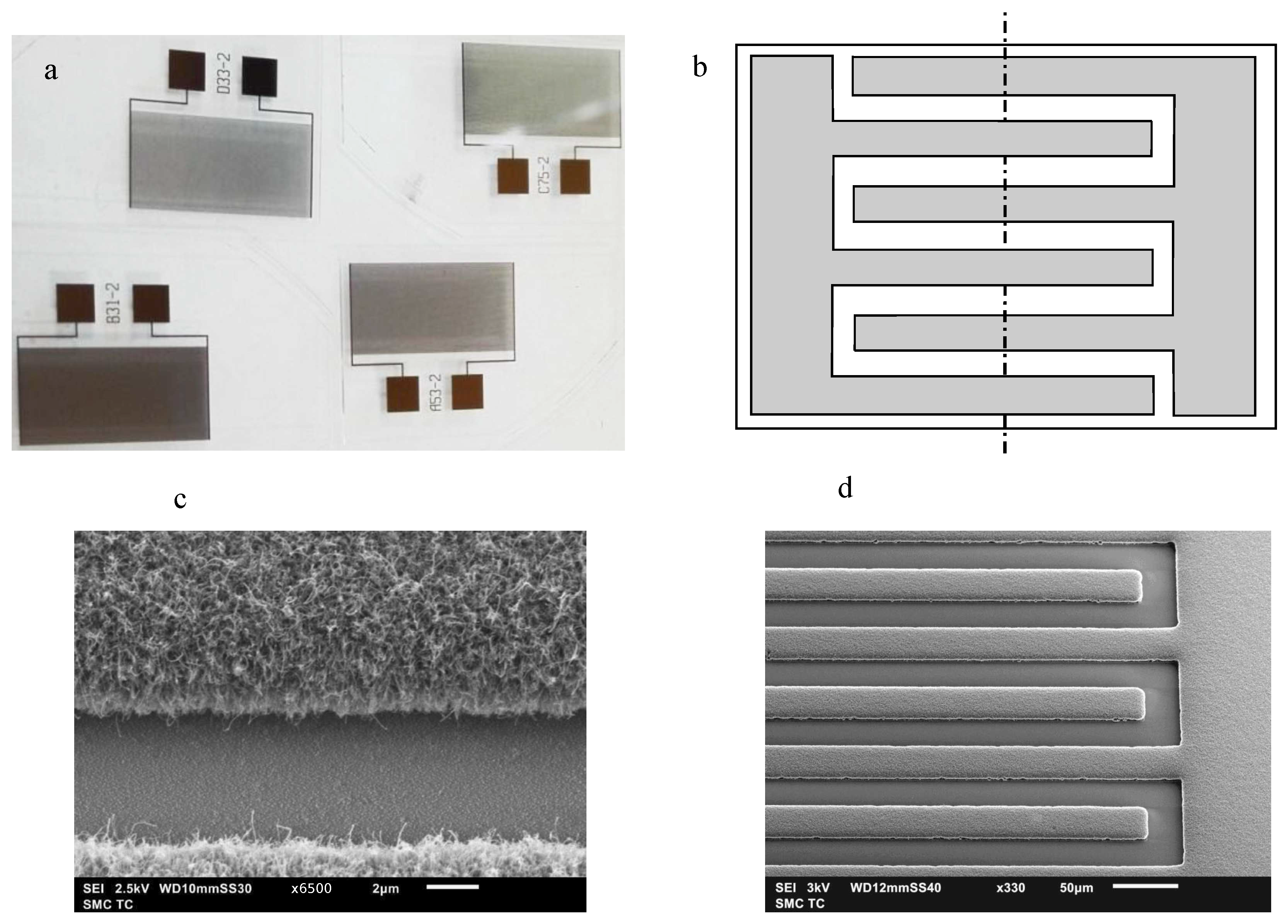
Planar micro-supercapacitors (PMSCs) are micro-scale electrochemical energy storage devices that can be embedded in a chip and integrated with other microelectronic devices. Different materials were suggested for electrodes of PMSC including graphene, nanowires, multiwalled carbon nanotubes (MWCNT), and conducting polymers (see review [1] and references therein). With an in-plane interdigital structure (Figure 1a,b), the PMSCs have a better performance than the conventional sandwich-like analogs of similar size [1]. Due to the spatial separation of the electrodes there is no need for a separator and organic binders. This simplifies the design and simulation of the device [2]. Interdigitized PMSCs possess excellent mechanical and electrical characteristics [3]. Due to design, the decreased ionic diffusion path between electrodes leads to small ion transport resistance, that results in higher power capability [3]. The high electrical conductivity of electrodes and their porosity can mitigate the ion diffusion resistance caused by the electrolyte viscosity [4].
An important problem is the development of reliable models for engineering calculations and diagnostics of PMSC. The simplest way is to extend the effective models of standard supercapacitors taking the geometry and specifics of PMSCs into account. One of the successful directions in phenomenological modeling of conventional supercapacitors is based on the use of fractional calculus [5,6,7,8,9,10,11,12]. Usually, these models are formulated in terms of equivalent circuits containing a constant phase element (CPE) sometimes called a capacitor of fractional order or a fractal element [13,14,15]. This element has an impedance with a frequency dependence proportional to . Bertrand, Sabatier et al., and Allagui et al. [8,16,17,18] have shown that fractional order models can effectively describe the dynamical behavior of electrochemical power sources and can be used to build SOC (state of charge) and/or SOH (state of health) estimators. Fractional differential models of supercapacitors were used to describe their operation in pulse power systems [19], to describe the impedance in a frequency range [5,7,20], to study temporal response of supercapacitors [11,21,22,23], to identify parameters from transient characteristics [24,25], to control supercapacitor systems using fractional state models [7], or fractional nonlinear systems [8,26].
In this paper, for the first time, a fractional differential model for PMSC is proposed. We show that the response of the studied supercapacitors with carbon nanotube-based electrodes is linear and the system is time-invariant. The proposed model well describes the behavior of PMSC that is confirmed by various experimental methods. We assume that the use of electrodes with an array of rod-like nanostructures should reduce the role of nonlinear effects in PMSC behavior. The effect of weak disordering of CNT array for increased height is considered in the framework of a distributed-order subdiffusion model.
2. Carbon Nanotubes in Planar Microsupercapacitors
The studied PMSC samples were fabricated on silicon or borosilicate glass substrates by means of standard microelectronics technologies. In the case of silicon substrates, they were pre-oxidized to form a layer of high-quality dielectric. The oxide thickness was ~0.3 μm. Next, a layer of metal (titanium) was applied to the plates. The measurements were carried out under normal atmospheric conditions. During measurement, the samples were placed into the shielded volume to protect against electromagnetic interference. Contacting the electrodes on the chip was carried out using silver-plated clamps. Multiwalled carbon nanotubes were synthesized by catalytic PECVD process (see details in [27]) (Figure 1). The capacities of a supercapacitor with a solid electrolyte based on polyvinyl alcohol (PVA) were investigated. Phosphoric acid H3PO4 or lithium chloride LiCl were used as the ion-conducting agent.
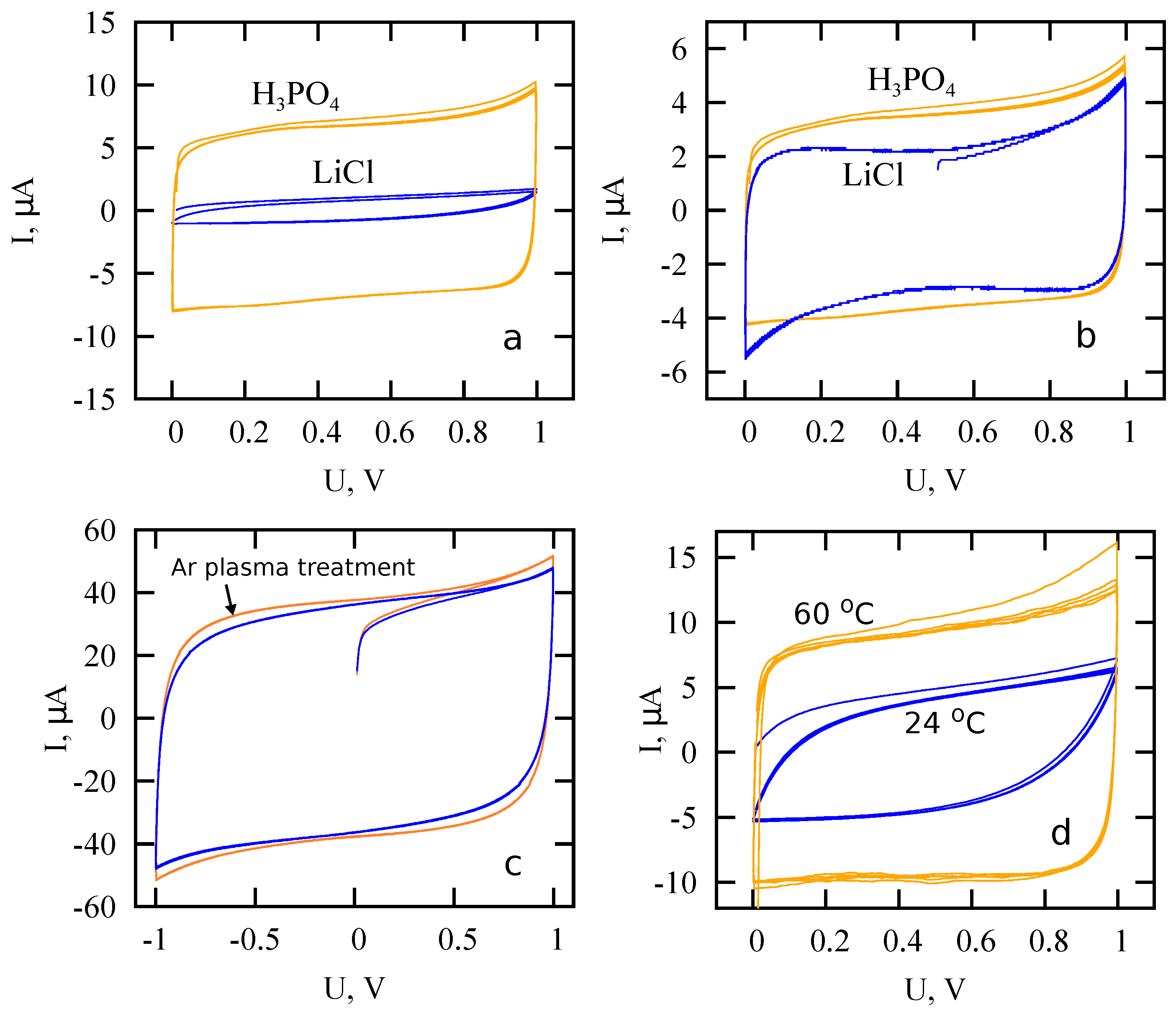
The model developed here is applied to description of PMSC with electrodes composed of MWCNT forest. Two samples of PMSC are analyzed. They are labeled as D33 and A53, and differ in the width of stripes with MWCNTs: 30 μm for D33 and 50 μm for A53. Otherwise, they are the same, including the area. The measured voltammograms (Figure 2) for fabricated PMSCs demonstrate shapes indicating the absence of electrochemical reactions on electrode-electrolyte interface. These shapes are typical for supercapacitors, where electric double layer plays the main role in charging kinetics. As shown below, these samples are characterized by linear response uniform in time that make these devices very convenient for description and prediction of their behavior under various conditions.
3. Linear Response and Anomalous Diffusion Model
In this section, we consider the linear response in terms of the integral equation describing a renewal generally non-Markovian process. By using the Mellin tranform of its kernel, it can be shown that a time-invariant dynamical process obeys a fractional differential equation of a complex order without additional assumptions [28]. The process is characterized by the order (spectral) distribution, so this representation incorporates both the standard Debye process and the non-Debye process family depending on choice of the spectral distribution.
Generally speaking, the object under investigation in the linear response theory (LRT) is an abstract system with two points: input and output. The input signal and output signal are linked via some functional relation
Here, F is a response functional and a denotes an initial moment of input signal appearance: for . The lower limit a of the functional can be taken as −∞, which allows to include in consideration signals appeared in remote past or composed of several segments separated by silence intervals. For short, we will write instead of .
In the frame of LRT, the response functional F should satisfy the following two requirements.
- It is causal: if for all then for all .
- It is linear: for any pair of functions and of some family of functions and any pair of constants and , the following equality takes place:
This functional can be represented in the following integral form,
- If the kernel K is invariant with respect to shift, , and for , we deal with the Standard Linear Response Theory (SRLT).
The response formula (1) takes the form of a convolution integral
An interesting behavior of discharging current in Panasonic supercapacitors (0.22, 0.47 and 1 F) was revealed in [22,23]. This behavior conforms neither of known models based on equivalent circuit because the response is nonuniform in time. Here, we will show that the response of PMSC-MWCNT is linear and the system is time-invariant.
The invariance of response kernel with respect to shift in time opens a wide field for using such power analytical tools as integral transforms. The Mellin transform casts additional light on the sense of fractional operators. Representing function via its Mellin transform
and inserting the result into integral term of Equation (2):
Here,
and
is an integral operator of complex order . Passage from the integral to fractional derivatives can be realized say by means of regularization procedure (derivation of a finite part under ). After multiplying on the weight factor and integrating over , this term yields the fractional derivative of distributed order according to the spectral function [29,30]. As a result, Equation (2) takes the form
The spectral function defines the LRT kinetics and links it with dynamics of an open system [28].
The application of fractional equations to the analysis of supercapacitors is usually justified by heterogeneity and complexity of porous electrodes [16,23,31,32,33]. These equations are often interpreted in terms of anomalous diffusion processes. Anomalous diffusion is usually associated with power law expansion of the diffusion packet, . The case corresponds to subdiffusion, and the case to superdiffusion.
Different specific mechanisms can lead to anomalous diffusion processes [33,34]. The features of anomalous diffusion are often described within the continuous time random walk (CTRW) model. The decoupled version of CTRW model implies that different jump lengths and waiting (trapping) times between two successive jumps are independent random variables. Fractional-order diffusion equation can be obtained as the asymptotic equation of CTRW with power law distributions of random trapping times : (). Considering CTRW with space dependent jump probabilities, Barkai et al. [35] derived a time-fractional Fokker–Planck equation (FFPE) for the case, when the mean waiting time diverges. FFPE describes anomalous diffusion in an external force field, it is derived in the following form [35,36],
where is particle concentration, is an external potential, K is a generalized diffusion coefficient, is the thermal energy.
Here,
is the Riemann–Liouville derivative of fractional order [37]. Fundamental solutions to Equation (3) can be found in [34,35,38].
The fractional diffusion equation for the simplest case has the following form [39],
The Fourier transform of Equation (4) leads to the expression
The flux density for diffusion described by (4) takes the form
The subdiffusive generalization of Warburg’s impedance for a semi-infinite medium can be written in the form [40]
Here, B is a frequency-independent parameter.
Based on fractional Equations (3) and (4), different generalizations of diffusion impedances can be obtained for different geometries and boundary conditions (see [32,40,41,42] and references therein). In our recent paper [43], effects produced by ion subdiffusion in lithium-ion cell are described within the fractional-order generalization of the single-particle model. Here, we use relation of fractional-order impedance to anomalous ion diffusion to interpret the behavior of PMSC.
4. Equivalent Circuit Model
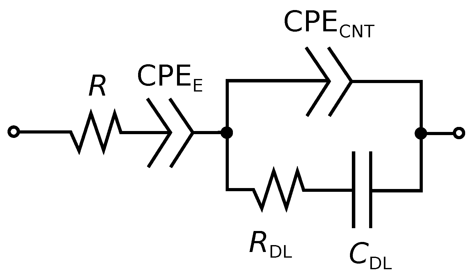
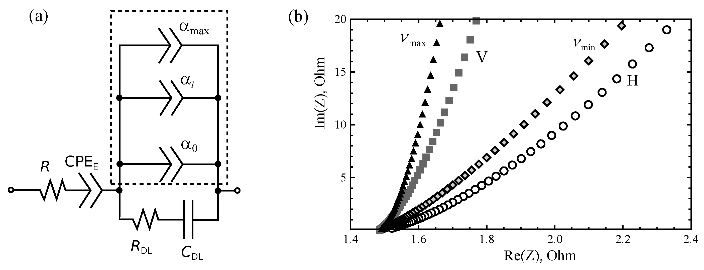
Considering the anomalous diffusion of ions in planar electrodes of PMSC and electrolyte in the interelectrode space, we obtained the following simple equivalent circuit of PMSC (Figure 3). It contains CPEs corresponding to ion subdiffusion in the MWCNT array and, in the interelectrode space, a capacitor and a resistor related to the electric double layer capacity and electrolyte resistance. The corresponding impedance is
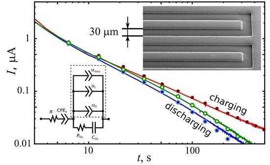
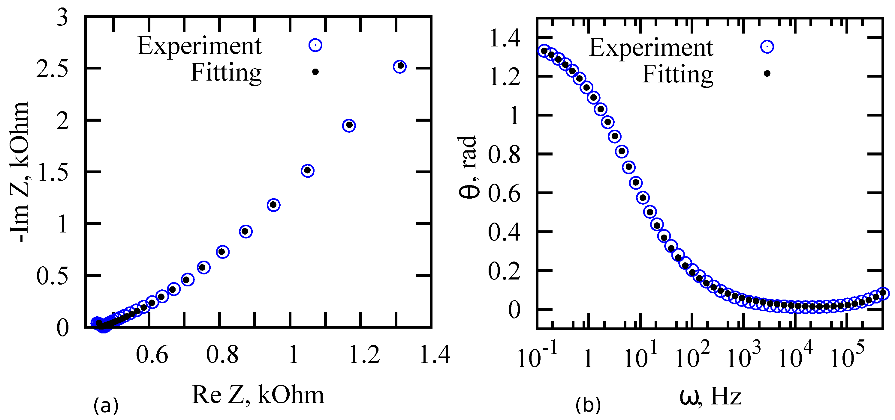
Fitting measured impedance spectra, we determined parameters of equivalent circuit for samples D33 and A53 at room temperature (Table 1). To fit the data, we used the program “EIS Spectrum Analyzer” [44]. An example of such fitting for D33 sample is shown in Figure 4. The value of parameter can be explained by the weak influence of ion diffusion in the interelectrode space on the impedance spectrum; therefore, the interelectrode region can be described using a series-connected resistor and an almost “ideal” capacitance. Parameter is related to ion subdiffusion in MWCNT array. According to Equation (7), value corresponds to subdiffusion parameter .
To find electric current as a response of PMSC, we use the numerical inverse Laplace transformation of the following relation: . Note that usually this relation leads to disagreement of numerical results with measured data, because depends on operating voltage and it can not be considered as a constant characteristic of the device for all voltages. Moreover, nonlinear effects can take place, whereas is obtained for the linearized process.
We use the following input voltage signals and their Laplace transforms.
For potentiostatic charging and its Laplace transform are
where H is the Heaviside function. For the discharging process, we have
where is a charging time. To plot discharging curves in log-log scale, we shift obtained in time to charging duration .
For cyclic voltammetry, the following voltage signal is used
Its Laplace transform has the form
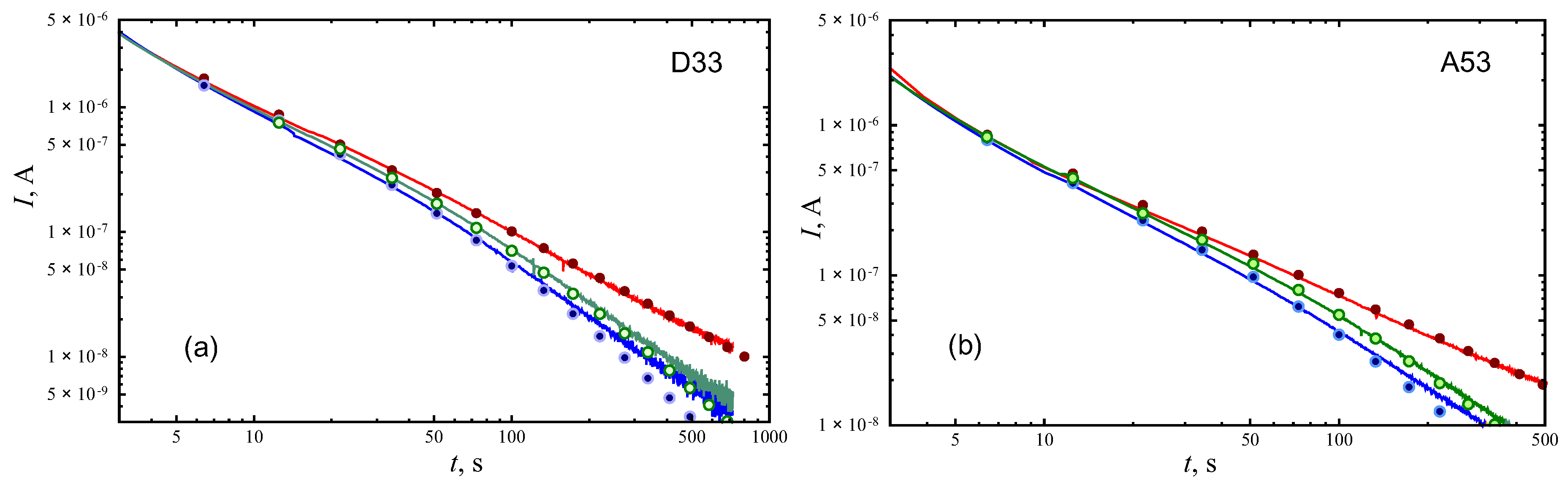
We use the Numerical Laplace Inversion package (Wolfram Mathematica) [45] to invert the Laplace transform . Calculated charging and discharging curves, and voltammograms are shown in Figure 5 and Figure 6 and compared with experimental data. There were no fitting parameters, all parameters have been determined from impedance spectra. Thus, we observe quite satisfactory agreement of model responses with experimental data. This means that the PMSC response in potentiostatic and cyclic voltammetry measurements are linear and uniform in time and parameters of equivalent circuit model do not depend on operating voltages.
Effective capacities of the studied PMSC are estimated to be 102 μF for D33 and 54 μF for A53. D33 is characterized by a smaller electrode stripe width (30 μm) in comparison with A53 (50 μm). The difference in capacities of these samples can be explained by the difference in surface area of contact between the MWCNT array and electrolyte. Despite the fact that the MWCNT array is porous and saturated with electrolyte, it is quite dense and the surface layers of the MWCNT array-electrolyte contact play the main role.
The deviation of the tails of theoretical discharge curves from the experimental data can be explained by variations in the parameter of the constant phase element considered in the next section. These variations can be related to disordering of the array with the height of MWCNT nanotubes.
5. Distributed-Order Fractional Model
To determine the dependence of PMSC capacitance on nanotube height, the MWCNT arrays with similar morphology, but of different heights, were obtained by varying the synthesis time. The dependence of array height on the synthesis time is shown in Figure 7 (left panel). Next, the capacitances of PMSC with PVA+LiCl electrolyte were measured. Figure 7 (right panel) shows the dependence of specific capacity on the height of the array. The capacitive efficiency of using the MWCNT array height h, or ratio , decreases with h. The use of hydrophilic treatments can increase the PMSC capacity by activating the unused area of MWCNT array, however, the power of the device does not increase. Such behavior can be explained by the small variation of the morphology of MWCNT forest for increased heights. These changes can modify the type of ion diffusion inside electrode at different heights (e.g., decrease the subdiffusion exponent). Based on this assumption, we propose distributed-order fractional circuit model and derive corresponding impedances for different distribution of subdiffusion parameter on height.
Consider two cases of distributed-order fractional models for PMSC. The first model implies subdiffusive behavior of fractional order homogeneously distributed over entire volume of electrodes. The second case assumes changing of subdiffusion exponent (fractional order) with height of the array. We show that these models lead to different PMSC impedances and the second case is more preferable to describe our measurements.
5.1. Subdiffusion Exponent Distributed Over Electrodes
For distributed-order fractional model, the subdiffusion equation can be written in the following form [33],
where is a probability density function for subdiffusion exponent , K is a generalized diffusion coefficient.
Equation (9) can be derived from the continuity equation with the following relation between current density and concentration:
Using the Fourier transformation of this distributed-order fractional Fick’s law,
and solution of the diffusion equation in the Fourier domain,
we obtain the following impedance,
For the case of weak dependence of on and uniform distribution of order between and , the impedance takes the form
where B is a constant parameter.
5.2. Variation of Subdiffusion Order with MWCNT Height
Let us assume the presence of variation in morphology of CNT forest with height of array. Subdiffusion perpendicular to MWCNT inside the electrodes is described by Equation (4), but the order depends on height. A separate layer of thickness can be characterized by impedance Equation (7). These layers are assumed to operate in parallel, and the equivalent circuit presented in Figure 8 should be used instead of the previous model shown in Figure 3.
As a result, we obtain the following impedance of anomalous diffusion in electrodes,
If we assume uniform distribution of between and and constant , we have
In Figure 8b, Nyquist plots are presented for four cases of subdiffusion index values. Points denoted as and corresponds to impedance of the circuit presented in Figure 8 with single -CPE, characterized by or . Points denoted by V (volume) and H (height) correspond to the similar circuit including impedances described by Equation (10) or Equation (12), respectively. The shapes of these Nyquist plots look similar, but slope strongly depend on the type of distribution of .
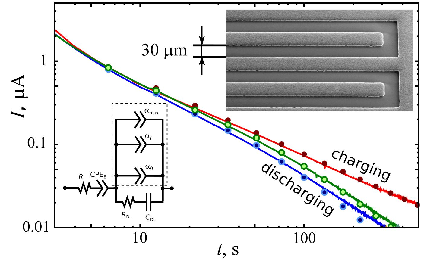
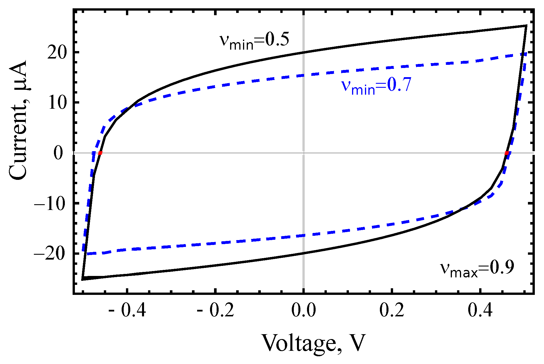
Figure 9 demonstrates charging and discharging curves and voltammograms for the circuit presented in Figure 8 with , . Other parameters are Ohm, sβ/Ohm, , , μF. Discharging curves indicate the presence of the memory effect, i.e., dependence on the charging prehistory. Cyclic voltammograms of the distributed-order model have the form similar to the single order model. The difference can be seen by variation of . Figure 10 shows two IV-curves for and . Parameters are the same as for Figure 9 except . Due to effect of disordering, smaller values of can be related to higher MWCNT array. For increased height of array, the capacity of PMSC grows, but the dependence of C on h is not direct proportionality. The shape of cyclic voltammogram for the same scanning rate is changed. This shape is closer to rectangle for higher values of . This is qualitative explanation of the behavior observed in Figure 7.
6. Conclusions
We studied the behavior of PMSC with electrodes of MWCNT array under sinusoidal excitation, step voltage input, and sawlike voltage input. Studied PMSC samples were fabricated on glass substrates by means of standard microelectronics technologies. MWCNTs were synthesized by a catalytic PECVD process. For the first time, a fractional differential model for planar supercapacitor is proposed. The corresponding equivalent circuit model, taking the anomalous diffusion of ions in the array and interelectrode space into account, successfully describes the measured impedance spectra. We demonstrate that the response of the investigated micro-supercapacitors is linear and uniform in time. The numerical inversion of the Laplace transforms for electric current response in an equivalent circuit with a given impedance leads to results consistent with potentiostatic measurements and cyclic voltammograms. Thus, the use of electrodes based on an ordered array of nanotubes reduces the role of nonlinear effects in the behavior of a supercapacitor. In addition, the effect of the disordering of nanotubes with increasing array length on the impedance of a supercapacitor is discussed in the framework of a distributed-order subdiffusion model. The dependence of PMSC capacitance on the height of MWCNT arrays in electrodes is measured. The capacity grows with h, while the ratio decreases. The explanation of such behavior is given within the fractional differential model assuming modification of the array morphology for the increased height that leads to a variation of the subdiffusion exponent.
Author Contributions
Conceptualization, E.P.K., V.V.S. and R.T.S.; methodology, R.T.S.; software, R.T.S.; validation, E.P.K. and R.T.S.; formal analysis, R.T.S. and E.P.K.; resources, V.V.S.; data curation, V.V.S.; writing–original draft preparation, R.T.S.; writing–review and editing, R.T.S. and E.P.K.; supervision, V.V.S.; project administration, V.V.S. and E.P.K.; funding acquisition, E.P.K. and R.T.S. All authors have read and agreed to the published version of the manuscript.
Funding
This work is supported by the Ministry of Science and Higher Education of the Russian Federation through the assignment of 2020 year for Scientific-Manufacturing Complex “Technological Centre”. Renat Sibatov acknowledges the financial support from the Russian Science Foundation (project 19-71-10063).
Conflicts of Interest
The authors declare no conflict of interest.
References
- Wu, Z.S.; Feng, X.; Cheng, H.M. Recent advances in graphene-based planar micro-supercapacitors for on-chip energy storage. Natl. Sci. Rev. 2014, 1, 277–292. [Google Scholar] [CrossRef] [Green Version]
- Chen, Y.T.; Ma, C.W.; Chang, C.M.; Yang, Y.J. Micromachined Planar Supercapacitor with Interdigital Buckypaper Electrodes. Micromachines 2018, 9, 242. [Google Scholar] [CrossRef] [Green Version]
- Hu, H.; Pei, Z.; Ye, C. Recent advances in designing and fabrication of planar micro-supercapacitors for on-chip energy storage. Energy Storage Mater. 2015, 1, 82–102. [Google Scholar] [CrossRef]
- Shao, Y.; Li, J.; Li, Y.; Wang, H.; Zhang, Q.; Kaner, R.B. Flexible quasi-solid-state planar micro-supercapacitor based on cellular graphene films. Mater. Horizons 2017, 4, 1145–1150. [Google Scholar] [CrossRef]
- Quintana, J.; Ramos, A.; Nuez, I. Identification of the fractional impedance of ultracapacitors. Fract. Differ. Its Appl. 2006, 2, 432–436. [Google Scholar] [CrossRef]
- Martin, R.; Quintana, J.J.; Ramos, A.; de la Nuez, I. Modeling of electrochemical double layer capacitors by means of fractional impedance. J. Comput. Nonlinear Dyn. 2008, 3, 021303. [Google Scholar] [CrossRef]
- Dzielinski, A.; Sierociuk, D. Ultracapacitor modelling and control using discrete fractional order state-space model. Acta Montan. Slovaca 2008, 13, 136–145. [Google Scholar]
- Bertrand, N.; Sabatier, J.; Briat, O.; Vinassa, J.M. Embedded fractional nonlinear supercapacitor model and its parametric estimation method. IEEE Trans. Ind. Electron. 2010, 57, 3991–4000. [Google Scholar]
- Elwakil, A.S. Fractional-order circuits and systems: An emerging interdisciplinary research area. IEEE Circuits Syst. Mag. 2010, 10, 40–50. [Google Scholar] [CrossRef]
- Freeborn, T.J.; Maundy, B.; Elwakil, A.S. Fractional-order models of supercapacitors, batteries and fuel cells: A survey. Mater. Renew. Sustain. Energy 2015, 4, 9. [Google Scholar] [CrossRef] [Green Version]
- Sibatov, R.; Uchaikin, V.; Ambrozevich, S. Fractional derivative formalism for non-destructive insulation diagnosis by polarization–depolarization current measurements. J. Vib. Control. 2016, 22, 2109–2119. [Google Scholar] [CrossRef]
- Jesus, I.S.; Tenreiro Machado, J. Application of integer and fractional models in electrochemical systems. Math. Probl. Eng. 2012, 2012, 248175. [Google Scholar] [CrossRef]
- Westerlund, S.; Ekstam, L. Capacitor theory. IEEE Trans. Dielectr. Electr. Insul. 1994, 1, 826–839. [Google Scholar] [CrossRef]
- Biswas, K.; Bohannan, G.; Caponetto, R.; Lopes, A.M.; Machado, J.A.T. Fractional-Order Devices; Springer: Berlin/Heidelberg, Germany, 2017. [Google Scholar]
- Gil’mutdinov, A.K.; Ushakov, P.A.; El-Khazali, R. Fractal Elements and their Applications; Springer: Berlin/Heidelberg, Germany, 2017. [Google Scholar]
- Sabatier, J. Fractional Order Models for Electrochemical Devices. In Fractional Dynamics; Sciendo Migration: Boston, MA, USA, 2015; pp. 141–160. [Google Scholar]
- Allagui, A.; Freeborn, T.J.; Elwakil, A.S.; Fouda, M.E.; Maundy, B.J.; Radwan, A.G.; Said, Z.; Abdelkareem, M.A. Review of fractional-order electrical characterization of supercapacitors. J. Power Sources 2018, 400, 457–467. [Google Scholar] [CrossRef]
- Kopka, R. Changes in Derivative Orders for Fractional Models of Supercapacitors as a Function of Operating Temperature. IEEE Access 2019, 7, 47674–47681. [Google Scholar] [CrossRef]
- Cahela, D.R.; Tatarchuk, B. Impedance modeling of nickel fiber/carbon fiber composite electrodes for electrochemical capacitors. In Proceedings of the IECON’97 23rd International Conference on Industrial Electronics, Control, and Instrumentation (Cat. No.97CH36066), New Orleans, LA, USA, 14 November 1997; Volume 3, pp. 1080–1085. [Google Scholar]
- Mahon, P.J.; Paul, G.L.; Keshishian, S.M.; Vassallo, A.M. Measurement and modelling of the high-power performance of carbon-based supercapacitors. J. Power Sources 2000, 91, 68–76. [Google Scholar] [CrossRef]
- Wang, Y.; Hartley, T.T.; Lorenzo, C.F.; Adams, J.L.; Carletta, J.E.; Veillette, R.J. Modeling ultracapacitors as fractional-order systems. In New Trends in Nanotechnology and Fractional Calculus Applications; Springer: Berlin/Heidelberg, Germany, 2010; pp. 257–262. [Google Scholar]
- Uchaikin, V.; Sibatov, R.; Ambrozevich, S. Comment on “Review of characterization methods for supercapacitor modelling”. J. Power Sources 2016, 307, 112–113. [Google Scholar] [CrossRef]
- Uchaikin, V.; Ambrozevich, A.; Sibatov, R.; Ambrozevich, S.; Morozova, E. Memory and nonlinear transport effects in charging–discharging of a supercapacitor. Tech. Phys. 2016, 61, 250–259. [Google Scholar] [CrossRef]
- Dzieliński, A.; Sarwas, G.; Sierociuk, D. Time domain validation of ultracapacitor fractional order model. In Proceedings of the 49th IEEE Conference on Decision and Control (CDC), Atlanta, GA, USA, 15–17 December 2010; pp. 3730–3735. [Google Scholar]
- Freeborn, T.J.; Maundy, B.; Elwakil, A.S. Measurement of supercapacitor fractional-order model parameters from voltage-excited step response. IEEE J. Emerg. Sel. Top. Circuits Syst. 2013, 3, 367–376. [Google Scholar] [CrossRef]
- Bertrand, N.; Sabatier, J.; Briat, O.; Vinassa, J.M. Fractional non-linear modelling of ultracapacitors. Commun. Nonlinear Sci. Numer. Simul. 2010, 15, 1327–1337. [Google Scholar] [CrossRef]
- Lebedev, E.; Kitsyuk, E.; Gavrilin, I.; Gromov, D.; Gruzdev, N.; Gavrilov, S.; Dronov, A.; Pavlov, A. Fabrication technology of CNT-Nickel Oxide based planar pseudocapacitor for MEMS and NEMS. J. Physics Conf. Ser. 2015, 643, 012092. [Google Scholar] [CrossRef] [Green Version]
- Uchaikin, V. On fractional differential Liouville equation describing open systems dynamics. Belgogrod State Univ. Sci. Bull. Math. Phys. 2014, 37, 58–67. [Google Scholar]
- Chechkin, A.V.; Gorenflo, R.; Sokolov, I.M.; Gonchar, V.Y. Distributed order time fractional diffusion equation. Fract. Calc. Appl. Anal. 2003, 6, 259–280. [Google Scholar]
- Sokolov, I.; Chechkin, A.; Klafter, J. Distributed-order fractional kinetics. arXiv 2004, arXiv:0401146. [Google Scholar]
- Allagui, A.; Freeborn, T.J.; Elwakil, A.S.; Maundy, B.J. Reevaluation of performance of electric double-layer capacitors from constant-current charge/discharge and cyclic voltammetry. Sci. Rep. 2016, 6, 38568. [Google Scholar] [CrossRef] [PubMed]
- Sibatov, R.T.; Uchaikin, V.V. Fractional kinetics of charge carriers in supercapacitors. Appl. Eng. Life Soc. Sci. 2019, 87. [Google Scholar] [CrossRef]
- Uchaikin, V.V.; Sibatov, R.T. Fractional Kinetics in Solids: Anomalous Charge Transport in Semiconductors, Dielectrics, and Nanosystems; World Scientific: Singapore, 2013. [Google Scholar]
- Metzler, R.; Klafter, J. The random walk’s guide to anomalous diffusion: A fractional dynamics approach. Phys. Rep. 2000, 339, 1–77. [Google Scholar] [CrossRef]
- Barkai, E.; Metzler, R.; Klafter, J. From continuous time random walks to the fractional Fokker–Planck equation. Phys. Rev. E 2000, 61, 132. [Google Scholar] [CrossRef]
- Metzler, R.; Barkai, E.; Klafter, J. Deriving fractional Fokker–Planck equations from a generalised master equation. EPL (Europhys. Lett.) 1999, 46, 431. [Google Scholar] [CrossRef]
- Samko, S.G.; Kilbas, A.A.; Marichev, O.I. Fractional Integrals and Derivatives; Gordon and Breach Science Publishers: Yverdon Yverdon-les-Bains, Switzerland, 1993; Volume 1993. [Google Scholar]
- Uchaikin, V.V. Self-similar anomalous diffusion and Levy-stable laws. Physics-Uspekhi 2003, 46, 821. [Google Scholar] [CrossRef]
- Balakrishnan, V. Anomalous diffusion in one dimension. Phys. A Stat. Mech. Its Appl. 1985, 132, 569–580. [Google Scholar] [CrossRef]
- Bisquert, J.; Compte, A. Theory of the electrochemical impedance of anomalous diffusion. J. Electroanal. Chem. 2001, 499, 112–120. [Google Scholar] [CrossRef]
- Lenzi, E.; Evangelista, L.; Barbero, G. Fractional diffusion equation and impedance spectroscopy of electrolytic cells. J. Phys. Chem. B 2009, 113, 11371–11374. [Google Scholar] [CrossRef] [PubMed]
- Ciuchi, F.; Mazzulla, A.; Scaramuzza, N.; Lenzi, E.; Evangelista, L. Fractional diffusion equation and the electrical impedance: Experimental evidence in liquid-crystalline cells. J. Phys. Chem. C 2012, 116, 8773–8777. [Google Scholar] [CrossRef]
- Sibatov, R.T.; Svetukhin, V.V.; Kitsyuk, E.P.; Pavlov, A.A. Fractional Differential Generalization of the Single Particle Model of a Lithium-Ion Cell. Electronics 2019, 8, 650. [Google Scholar] [CrossRef] [Green Version]
- Bondarenko, A.; Ragoisha, G. Progress in Chemometrics Research; Nova Science Publishers: New York, NY, USA, 2005; pp. 89–102. [Google Scholar]
- Valkó, P.P.; Abate, J. Comparison of sequence accelerators forthe Gaver method of numerical Laplace transform inversion. Comput. Math. Appl. 2004, 48, 629–636. [Google Scholar] [CrossRef] [Green Version]
Figure 1.
Planar supercapacitors studied in this work: photographs of several samples (a), planar geometry of PMSC (b), SEM images of multiwalled carbon nanotube (MWCNT) array in electrodes for different resolutions (c,d).
Figure 1.
Planar supercapacitors studied in this work: photographs of several samples (a), planar geometry of PMSC (b), SEM images of multiwalled carbon nanotube (MWCNT) array in electrodes for different resolutions (c,d).

Figure 2.
Cyclic voltammograms of planar micro-supercapacitor with solid electrolyte PVA + H3PO4 for scanning rates 50 mV/s (a) and 25 mV/s (b) as well as for the plasma treated sample (c) and curves measured at two different temperatures (d).
Figure 2.
Cyclic voltammograms of planar micro-supercapacitor with solid electrolyte PVA + H3PO4 for scanning rates 50 mV/s (a) and 25 mV/s (b) as well as for the plasma treated sample (c) and curves measured at two different temperatures (d).

Figure 3.
Simple equivalent circuit model of PMSC.

Figure 4.
Nyquist plot (a) and frequency dependence of phase shift (b) for PMSC (D33) with PVA + LiCl electrolyte. Circles are experimental data, dots are the result of fitting by impedance Equation (8).
Figure 4.
Nyquist plot (a) and frequency dependence of phase shift (b) for PMSC (D33) with PVA + LiCl electrolyte. Circles are experimental data, dots are the result of fitting by impedance Equation (8).

Figure 5.
Comparison of measured charging and discharging ( and 200 s) curves (lines) for PMSC D33 (a) and A53 (b) with linear responses predicted by the equivalent circuit model with parameters indicated in Table 1 (points).
Figure 5.
Comparison of measured charging and discharging ( and 200 s) curves (lines) for PMSC D33 (a) and A53 (b) with linear responses predicted by the equivalent circuit model with parameters indicated in Table 1 (points).

Figure 6.
Comparison of measured voltammograms (lines) for PMSC D33 (a) and A53 (b) with the linear responses predicted by the equivalent circuit model with parameters indicated in Table 1 (points).
Figure 6.
Comparison of measured voltammograms (lines) for PMSC D33 (a) and A53 (b) with the linear responses predicted by the equivalent circuit model with parameters indicated in Table 1 (points).
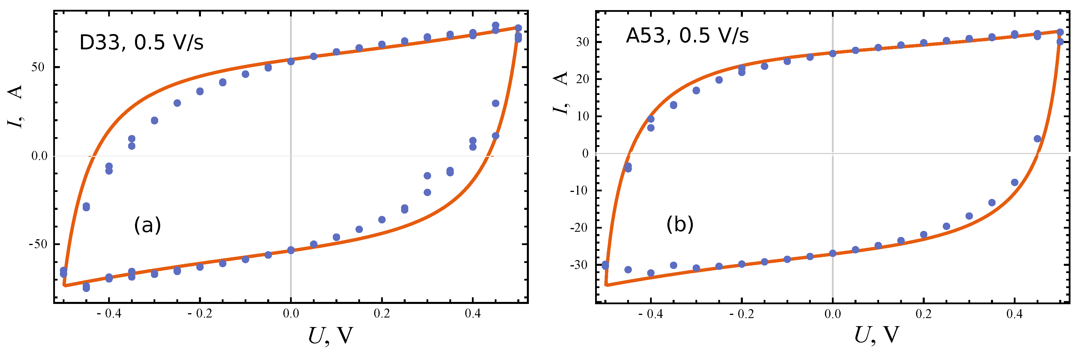
Figure 7.
Dependence of MWCNT height on duration of array synthesis (a) and the efficiency of using the MWCNT array height for the device capacitance (b). Circles correspond to experimental data, lines are approximation by a cubic polynomial function (a) and a linear function (b).
Figure 7.
Dependence of MWCNT height on duration of array synthesis (a) and the efficiency of using the MWCNT array height for the device capacitance (b). Circles correspond to experimental data, lines are approximation by a cubic polynomial function (a) and a linear function (b).
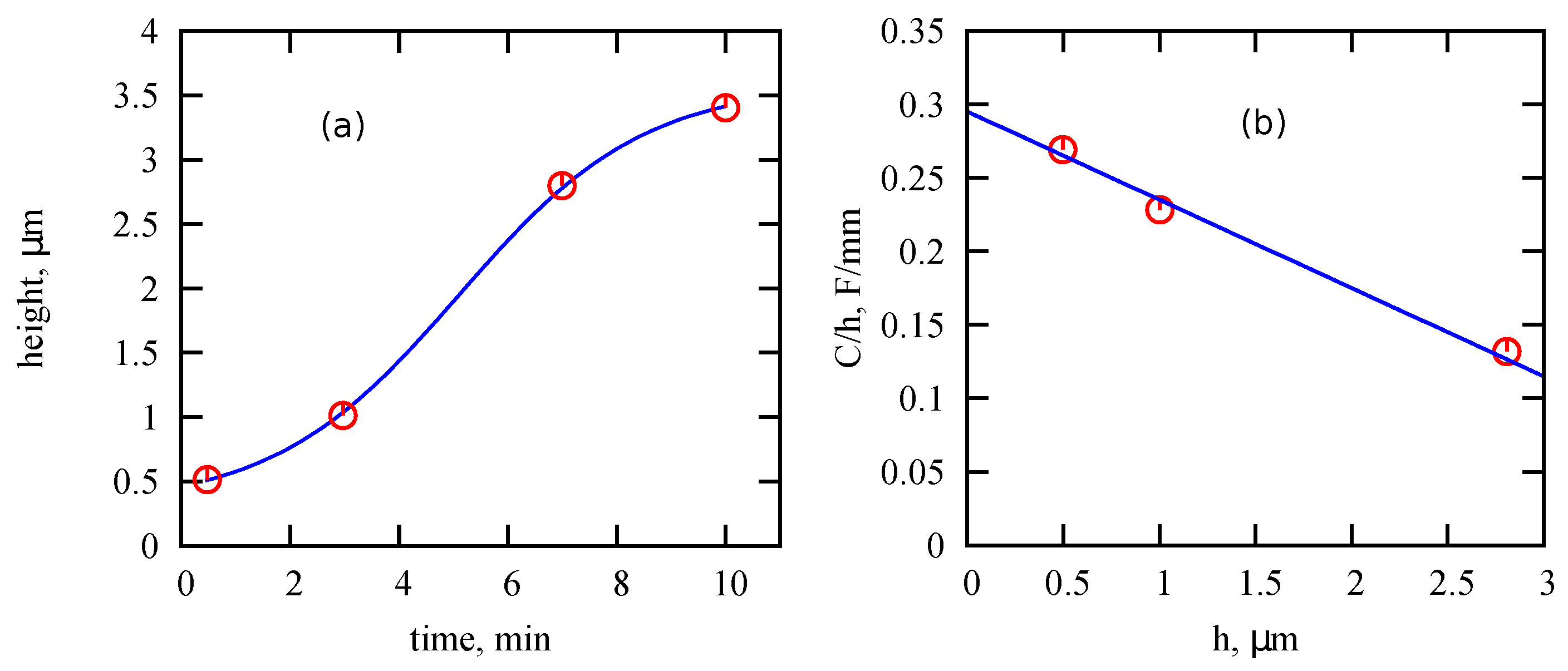
Figure 8.
(a) Distributed order fractional circuit model of PMSC. (b) Nyquist diagrams for four cases of fractional PMSC model.
Figure 8.
(a) Distributed order fractional circuit model of PMSC. (b) Nyquist diagrams for four cases of fractional PMSC model.

Figure 9.
Theoretical charging-discharging curves (a) and cyclic voltammograms (b) predicted by the distributed-order fractional model.
Figure 9.
Theoretical charging-discharging curves (a) and cyclic voltammograms (b) predicted by the distributed-order fractional model.
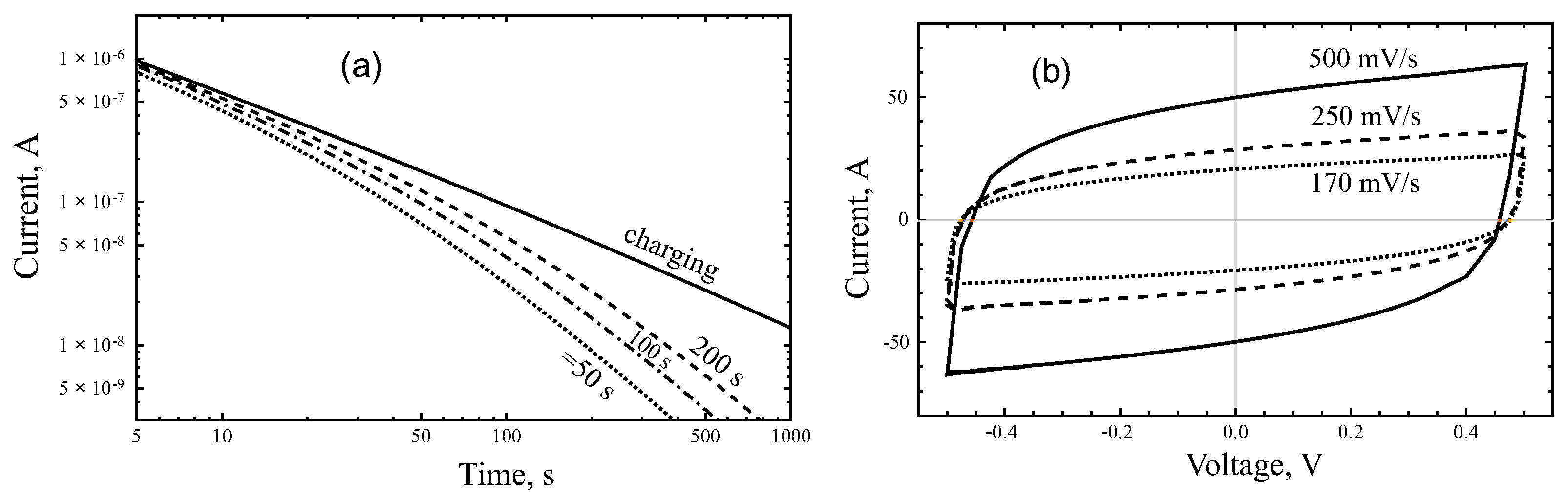
Figure 10.
Calculated cyclic voltammograms for the distributed-order fractional model of PMSC for two values of .
Figure 10.
Calculated cyclic voltammograms for the distributed-order fractional model of PMSC for two values of .


Table 1.
Parameters of the equivalent circuit model.
| Parameter | D33 | A54 |
|---|---|---|
| R, Ohm | 1450 | 1275 |
| , F | ||
| , Ohm | 0 | 0 |
| , sβ/Ohm | ||
| 1.0 | 0.91 | |
| , sα/Ohm | ||
| 0.70 | 0.78 |
© 2020 by the authors. Licensee MDPI, Basel, Switzerland. This article is an open access article distributed under the terms and conditions of the Creative Commons Attribution (CC BY) license (http://creativecommons.org/licenses/by/4.0/).
Share and Cite
MDPI and ACS Style
Kitsyuk, E.P.; Sibatov, R.T.; Svetukhin, V.V. Memory Effect and Fractional Differential Dynamics in Planar Microsupercapacitors Based on Multiwalled Carbon Nanotube Arrays. Energies 2020, 13, 213. https://doi.org/10.3390/en13010213
AMA Style
Kitsyuk EP, Sibatov RT, Svetukhin VV. Memory Effect and Fractional Differential Dynamics in Planar Microsupercapacitors Based on Multiwalled Carbon Nanotube Arrays. Energies. 2020; 13(1):213. https://doi.org/10.3390/en13010213
Chicago/Turabian StyleKitsyuk, Evgeny P., Renat T. Sibatov, and Vyacheslav V. Svetukhin. 2020. "Memory Effect and Fractional Differential Dynamics in Planar Microsupercapacitors Based on Multiwalled Carbon Nanotube Arrays" Energies 13, no. 1: 213. https://doi.org/10.3390/en13010213
Note that from the first issue of 2016, this journal uses article numbers instead of page numbers. See further details here.