Article

Analysis of Non-Equilibrium and Equilibrium Models of Heat and Moisture Transfer in a Wet Porous Building Material †

Institute of Heat Engineering, Faculty of Power and Aeronautical Engineering, Warsaw University of Technology, 00-665 Warsaw, Poland
*
Author to whom correspondence should be addressed.
This paper is an extended version of our paper published in XII International Conference on Computational Heat, Mass and Momentum Transfer (ICCHMT2019), Rome, Italy, 3–6 September 2019.
Energies 2020, 13(1), 214; https://doi.org/10.3390/en13010214
Submission received: 28 November 2019 / Revised: 23 December 2019 / Accepted: 26 December 2019 / Published: 2 January 2020

Abstract

:
In the proposed paper, non-equilibrium and equilibrium models of heat and moisture transfer through wet building materials are presented and compared. In the former, the mass transfer between liquid and gaseous moisture results from the difference between the partial pressure of water vapor and its saturation value. In the second model, the equilibrium between both phases is assumed. In the non-equilibrium model, liquid moisture can be in the continuous (funicular) or discontinuous (pendular) form. The transfer of moisture for each proposed model is tightly coupled with the energy transfer, which is assumed to be an equilibrium process. The time step and grid size sensitivity analysis of both numerical models are performed primarily. The verification of the model is based also on the numerical data available in literature. Finally, obtained with considered models, temporal variations of moisture content in three locations in the computational domain are compared. Reasonable conformity of results is reported, and discrepancies related to differences in formulations of models are discussed.

1. Introduction

Transfer of moisture in porous building materials is an important phenomenon related to the drying building structures. It includes concurrent multi-phase transfer of water in the multi-scale porous structure which is additionally accompanied by heat flow. Water may take the form of a gaseous phase as well as a continuous (funicular) or discontinuous (pendular) liquid phase.
Numerical modeling of related processes is a focus of concern for many researchers around the world. Several approaches to model combined moisture and heat transfer in various porous materials may be found in literature.
Early attempts to derive coupled balance equations of moisture and energy were undertaken by Whitaker [1]. The concept of representative elementary volume was utilized for the rigorous derivation of transport equations. Salagniac et al. [2] proposed a numerical model of drying a porous material during combined convective, infrared, and microwave heating. The one-dimensional model, based on the approach proposed in [3], consisted of energy, dry air, and total moisture balance equations. The infrared and microwave heating affects were treated as the surface and volumetric sources, respectively. Early models of combined heat, air, and moisture transfer in components of the building were developed and validated by several authors as a part of the Heat, Air and Moisture Standards Development (HAMSTAD) project [4].
A two-equation model of the process of drying wet building materials, which accounted for the presence of water and vapor, was proposed by Van Belleghem et al. [4,5]. Capillary pressure and temperature were assumed as independent variables. The model was utilized to study the concurrent capillary water transfer and vapor diffusion in one-dimensional (1D) and two-dimensional (2D) domains. This approach was found to be superior over those previously developed by the same authors [6,7], where transported variables were the relative mass fraction of water vapor and temperature. It was pointed out that the models presented in [6,7] were valid for the hygroscopic range only (i.e., for the relative humidity below 98%) where the water was discontinuous across the domain (i.e., in funicular form) and the diffusive transfer of water vapor was dominant. In all the models presented above, the effect of the motion of dry air was neglected. In turn, Janetti et al. [8] presented a two-equation model of moisture and heat transferred across porous building material (i.e., silicate brick). Relative humidity and temperature were assumed as independent variables. The model was implemented in the framework of the commercial package COMSOL. Results predicted with the proposed model were positively validated with experimental data. Belleudy et al. [9] proposed a computational model capable of accounting for the transfer of moisture and heat across walls of the complex structure and for accompanying leakage air flow between components of the wall. In the model three main phenomena were accounted for, namely vapor diffusion and capillary suction in the porous medium and advective moist air transfer through thin channels. The transport equations were expressed in terms of two parameters, namely the temperature of the medium and relative humidity. A model of the moisture transfer in the clay brick was developed Allam et al. [10]. This model was based on the same driving potentials used in [9].
The extended model of moisture and heat transfer in homogeneous porous building materials was presented in [11,12]. It consisted of four transport equations, describing vapor, dry air, liquid moisture, and energy transport. The densities of dry air and water vapor as well as liquid moisture volume fraction and temperature were used as independent variables.
The problem of concurrent moisture and energy transport was also solved in the context of hygroscopic porous textiles or fibrous materials [13]. In the model proposed in [13], temperature, water vapor concentration, moisture concentration in fibers, and water content in the fibrous batting were used as independent variables. This model accounted for moisture flow driven by the partial pressure of water vapor, the movement of liquid condensate, the existence of a supersaturation state in the condensing region, and dynamic moisture absorption by fibers in fibrous materials. In turn, in the model of hygrothermal behavior of protective garments subjected to high external radiative heat flux presented by Łapka et al. [14,15], the governing equations for moisture and heat flow were formulated using the volume fraction of bound water, vapor density, and temperature. The model developed by Łapka et al. [14,15] also dealt with conductive and radiative heat transfer accompanied by the diffusion of the vapor through fabrics and airgaps and with phase transition of moisture to or from the bound state in fabric fibers.
Recently, both models proposed in this paper were investigated in [16], but no radiative heat transfer at the dried surface was considered nor time step size or mesh density sensitivity analysis was performed. Presented temperature variations at the selected point in the domain were compared with the reference numerical data. A good coincidence of results predicted with the equilibrium model and the reference was observed.
In this study two different approaches to the coupled moisture and heat transfer are investigated. In the first one, the transfer of moisture has a non-equilibrium nature. To describe the transport processes the multi domain approach is adopted, so separate mass transfer equations for liquid water and water vapor are formulated, and interphase mass transfer processes are expressed as source terms, related also to microstructure of the porous medium. The mass transfer between liquid and gas phases is driven by the difference between the partial pressure of moisture in the gas phase and its saturation value. The local thermal equilibrium between all phases is assumed, so in the non-equilibrium model the independent variables are vapor density, water volume fraction and temperature. The second considered approach, the equilibrium one, assumes the existence of equilibrium mass and energy transfer between the phases. Two independent variables are used: total moisture content and temperature. On this basis the total moisture and energy transfer equations are formulated.
The former model is implemented as the in-house simulation code while the second one is implemented in the framework of the commercial software ANSYS Fluent® (v.19.2, ANSYS Inc., Canonsburg, PA, USA) using customization interfaces like user-defined function (UDF), user-defined memory (UDM), and user-defined scalar (UDS). Proposed approaches are justified by further plans regarding the development of simulation codes. The simplified, equilibrium model will be used for optimization of the drying process in the simple geometries considered only. This demands development of fast, robust software, even if simplified physics of the process is taken into account. The non-equilibrium model will be used in the future for full-scale simulations of the processes involving real geometries and coupled transport phenomena in building material and ambient air, thus it was implemented in the framework of the commercial software. This will allow for fast and easy application of complex three-dimensional (3D) geometries.
In the next sections of the paper both models are presented with relevant boundary and initial conditions as well as all closing relationships. Moreover, the considered case is described, and data needed in numerical simulations are presented. Then the time step and mesh size sensitivity analyses were carried out for both considered numerical models. Subsequently, the models are verified in the simplified way and the results predicted by them are compared in three points in the computational domain.

2. Descriptions of Models

2.1. General Assumptions

The considered building material, namely brick, is treated as a porous material. The solid phase is a material of brick in which pores, water, and humid air are present. Water can be in a continuous (funicular) or discontinuous (pendular) state. The sum of volume fractions of the solid phase, εs, liquid phase (funicular and pendular), εl, and vapor, εv, is equal to 1; so, εs + εl + εv = 1. Volume fraction of the solid phase is constant, so volume fraction of pores is also constant (i.e., εp = εl + εv = const). The amount of water in the pores of the building material changes due to transport driven by the gradient of the capillary pressure as well as evaporation and condensation processes, while the amount of vapor changes due to diffusion and phase change processes as well. The thermal equilibrium across phases is assumed in both models, so the single equation of energy transfer is considered. In the non-equilibrium model liquid and heat transfer are related to moisture movement, but in the pendular state of water they are neglected. The total pressure, p, in the porous medium is assumed constant and equal to 101,325 Pa, which allows for simplification of both mathematical models and elimination of the equation for balance of air [11,12]. In the two subsequent sections both models of concurrent moisture and heat transfer, namely the non-equilibrium and equilibrium ones, are presented. They are supplemented with closure relations as well as boundary and initial conditions, which are also presented below.

2.2. Non-Equilibrium Model

In the non-equilibrium model the finite rate of condensation and evaporation is assumed. Hence, the following separated balance equations for condensed water and water vapor are taken into account:
t ( ε g ρ v ) + j v = m ˙ l v
t ( ε l ρ l ) + j l = m ˙ l v
Mass fluxes of water vapor and water are related to density of vapor, ρv, and capillary pressure, pc, respectively, by the following formulas:
j v = D v , e f ρ v
j l = K l p c
where Dv,ef and Kl are the effective water vapor diffusivity and water permeability, respectively. All closure relations are listed in Section 2.4 and material properties are listed in Table 1. Intensity of evaporation and condensation, lv, is driven by the difference between the actual and equilibrium saturation density in pores of the wet building material and is given by the following equation:
m ˙ l v = { h v l a s ε l ε p ( ρ v , s a t ρ v ) for   evaporation h v l a s ( ρ v , s a t ρ v ) for   condensation
The coefficient hvl is the mass transfer coefficient between water vapor and water, while as describes pore area per unit volume. The mass flow rate per unit volume assumes a positive value for evaporation, and negative one for condensation. The εl/εp ratio denotes the part of the pore volume occupied by liquid moisture.
The equilibrium heat transfer between water, moist air, and solid material of brick is assumed, so the locally averaged temperature is equal to its phase-wise averaged counterparts and the following single energy balance equation is considered:
t [ ( ρ c ) e f T ] + ( j l h l ) + ( j v h v ) + ( j a h a ) = ( k e f T ) m ˙ l v Δ h l v .
where Δhlv is the latent heat of evaporation.

2.3. Equilibrium Model

The equilibrium model of moisture and heat flow in the porous building material consists of balance equations for total moisture and energy. The former is the sum of water and water vapor contents. After summation of transport Equations (1) and (2), the total moisture transport equation takes the following form:
W t + j l + j v = 0
while the energy transfer equation is as follows:
H t + ( j l h l ) + ( j v h v ) + ( j a h a ) = ( k e f T )
where the total volumetric moisture content and total enthalpy are given with the following equations:
W = W l + W g = ρ l ε l + ρ v ε g
H = ρ s ε s h s + ρ l ε l h l + ρ v ε g h v + ρ a ε g h a
Mass fluxes of water and water vapor are driven with gradients of capillary pressure and density of vapor, given by Equations (3) and (4), respectively. They can be expressed as functions of two independent variables (i.e., total moisture content, W, and temperature, T) in the following ways:
j v = D v T T + D v W W   and   j l = D l T T + D l W W
Thus, the moisture balance equation assumes the following form:
W t + [ ( D v T + D l T ) T + ( D v W + D l W ) W ] = 0
Based on the above representation of moisture fluxes and definitions of specific enthalpies (Section 2.4), the energy balance equation takes the following form:
t [ ( ρ c ) e f T ] + [ ( D v T c p , v + D l T c l + D a T c p , a ) T + ( D v W c p , v + D l W c l + D a W c p , a ) W ] T = ( k e f T ) m ˙ l v Δ h v l
The transport coefficients present in Equations (10)–(12) are defined as follows:
D v T = D a T = M a M v M g B T D v , e f p v T and D l T = K l p c T D v W = D a W = M a M v M g B T D v , e f p v W and D l W = K l p c W
The evaporation and condensation intensity is obtained from the equation:
m ˙ l v = d W v / d t
where the water content in the gaseous and liquid phase can be determined with the equation:
W v = W / ρ l ε p 1 / ρ l 1 / ρ v   and   W l = ε p W / ρ v 1 / ρ l 1 / ρ v .
The main difference between the presented models in this and previous sections is the way of accounting for the mechanism of evaporation and condensation. In the non-equilibrium model, it is driven by the difference between actual density of water vapor and its value corresponding to the saturation state, so the finite rate of water transport between water and humid air is accounted for. Rate of moisture transfer across the phase interface is also related to the local microstructure of the porous medium (area density) which enables more accurate modeling of underlying processes but also needs more specific closure relations. This statement of the problem requires at least three variables, which account for water content in liquid and vapor phases as well as temperature. In the fully equilibrium model, changes in the moisture content of the liquid and vapor forms are established immediately, so water content in the liquid and vapor phases are tightly coupled. In this model two variables are enough to capture concurrent moisture and heat transfer, namely total moisture content and temperature. Moisture content in both phases can be immediately determined with Equation (15).

2.4. Material Properties and Closure Relationships

The systems of transport equations, Equations (1), (2), and (6) as well as Equations (11) and (12), are closed by the following relationships [6]:
  • Pore area per unit volume:
    a s = 6 d a v ( 1 ε s )
  • Vapor diffusivity in pores:
    D v , e f = 2.61 10 5 M v ( 1 W W c a p ) C d r y B T [ 0.503 ( 1 W W c a p ) 2 + 0.497 ]
  • Effective thermal conductivity of the moist brick:
    k e f = k s + 0.0047 W
  • Water permeability in the brick:
    K l = 1.1437 10 9 [ 1 + ( 1.76 10 5 p c ) 4.3 ] 1.6
  • Vapor saturation pressure:
    p v , s a t = 614.3 exp ( 17.06 T 273.15 T 40.25 )
  • Modified saturation pressure:
    p v = p v , s a t exp ( p c M v ρ l B T )
  • Liquid saturation:
    s = ε l 1 ε s
  • Retention curve which was applied to find the capillary pressure:
    W ( p c ) = W c a p { 0.846 [ 1 + ( 1.394 10 5 p c ) 4 ] 0.75 + 0.154 [ 1 + ( 0.9011 10 5 p c ) 1.69 ] 0.408 }
  • Water vapor density for saturation conditions:
    ρ v = p v M ν B T
  • Effective heat capacity:
    ( ρ c ) e f = ε s ρ s c s + ε l ρ l c l + ε g ρ a c p , a + ε g ρ v c p , v
  • Specific enthalpies:
    h s = c s ( T T r e f ) and h v = c p , v ( T T r e f ) + Δ h v l h l = c l ( T T r e f ) and h a = c p , a ( T T r e f )
In addition to these relationships, the ideal gas relationship was applied for calculations of dry and moist air as well as vapor parameters. Some closure relations, like for vapor diffusivity, effective thermal conductivity, and water permeability, depend on the type of material and its microstructure. Therefore, they are measured and presented in the form of correlations.
All simulations presented in this paper were carried out for ceramic brick, whose thermophysical properties are presented in Table 1.

3. Numerical Implementation

3.1. Description of the Studied Case

Numerical calculations were carried out for drying ceramic brick with a thickness equal to L = 3 cm which is schematically presented in Figure 1. Only the top wall of the sample was in contact with the drying medium (i.e., air). The other walls (i.e., bottom and side walls) were adiabatic and impermeable for moisture. Therefore, moisture and heat transfer in the considered computational domain may be approximated by the one-dimensional (1D) transfer process. This case corresponds to an experimental setup in which only one surface of the sample is exposed to drying medium, while the others are insulated and sealed.
The top wall of the computational domain was in contact with ambient air which maintained a constant temperature and relative humidity equal to Tamb and φamb, respectively. On this wall boundary conditions for moisture and energy transfer equations were imposed. The formulation of both boundary conditions depends on the type of model, whether non-equilibrium or equilibrium, so details are presented separately.
For the non-equilibrium model, the boundary conditions for the moisture balance equations are related to the state of the water at the surface. For the first period of drying, in which water in the pendular state was present at the boundary and evaporation from the surface occurred, mass fluxes of gaseous and liquid moisture were as follows:
( D v , e f ρ v ) w = j v , w = 0
( K l p c ) w = j l , w = h m ( ρ v , w ρ g , w Y a m b )
These boundary conditions are valid for s > smin = 0.25, when the liquid saturation is higher than the minimal saturation for water in the pendular form. For the second period of drying, in which the liquid saturation dropped below the minimum saturation level (i.e., s < smin = 0.25) mass fluxes of gaseous and liquid moisture were as follows:
( D v , e f ρ v ) w = j v , w = h m ( ρ v , w ρ g , w Y a m b )
( K l p c ) w = j l , w = 0
The thermal boundary condition for Equation (6) on the top wall was as follows:
( k e f T ) w = h t ( T w T a m b ) + σ ( T w 4 T a m b , r a d 4 ) 1 / ε w + 1 / ε a m b 1 + Δ h l v j l , w
where the last term on the right-hand side of Equation (31) refers to liquid moisture evaporation or condensation on the top wall. The second term accounts for the surface radiative heat transfer between the heated surface and surroundings.
For the equilibrium model the unique boundary condition for the moisture and heat transfer were defined as follows:
j v , w + j l , w = h m ( ρ v , w ρ v , a m b )
( k e f T ) w + j v , w h v , w + j l , w h l , w = h t ( T w T a m b ) + σ ( T w 4 T a m b , r a d 4 ) 1 / ε w + 1 / ε a m b 1
where mass fluxes and enthalpies are given by Equations (9) and (25), respectively.
Boundary conditions parameters assumed in simulations were as follows: the temperature and relative humidity of drying air were equal to Tamb = 23.8 °C and ϕamb = 44%, respectively, the heat transfer coefficient was ht = 22.5 W/m2/K, while the mass transfer coefficient was hm = 0.0258 kg/m2/s. The radiative heat flux at the dried surface, present in boundary conditions, Equations (31) and (33), involved emissivities at the top wall and surrounding surfaces equal to εw = 0.93 and εamb = 0.97, respectively and the ambient radiation temperature was equal to Tamb,rad = 23.3 °C. The Stefan–Boltzmann constant was equal to σ = 5.67 × 10⁻⁸ W/m2/K4. Initial conditions for transport equations were as follows: the uniform brick temperature was T0 = 23.8 °C and the uniform water saturation was s0 = 97%, which corresponded to the volumetric moisture content of W0 = 126.1 kg/m3.

3.2. Numerical Implementation of Models

3.2.1. Non-Equilibrium Model

The non-equilibrium model defined by Equations (1), (2), and (6) with boundary and initial conditions given by Equations (27)–(31), was implemented in the framework of the finite volume method based commercial software ANSYS Fluent®. Development of the numerical model required application of advanced customization interfaces, such as the user defined function (UDF), user defined scalar (UDS), and user defined memory (UDM). The computational model was constrained to two-dimensional (2D) geometry. Numerical calculations were conducted in the following way: For the considered case the model was configured to simulate 1D moisture and heat transfer in the ceramic brick (see Figure 1). The basic mesh had Nx = 60 elements along the brick thickness, while only one element was used along the brick width. The basic time step size was equal to Δt = 5 s, which allowed for stable simulations to be carried out.

3.2.2. Equilibrium Model

The equilibrium model of moisture and heat transfer defined by Equations (11) and (12) with boundary and initial conditions given by Equations (32) and (33), was implemented in the framework of the in-house numerical code. The considered transport equations were discretized on the 1D control volume mesh. To simplify implementation of the boundary condition on the top surface, the “half” control volume was generated at this boundary and the outermost node was coincident with the surface.
The basic simulations were carried out for the uniform spatial 1D grid which had Nx = 60 elements across the computational domain. The implicit Euler scheme was applied for discretization of transient terms in both equations. The time step of Δt = 0.5 s was found to be enough to provide stable solutions. The idea of a separated solver was utilized. This means that in each iteration the balance equation for moisture, given by Equation (11), was solved first and then the supplementary material properties (Equations (17)–(19)), mass fluxes (Equations (3) and (4)), as well as volumetric moisture contents in gaseous and liquid phases (Equation (15)), were evaluated. In the last step the balance equation of energy, given with Equation (12), was solved.

4. Results and Discussion

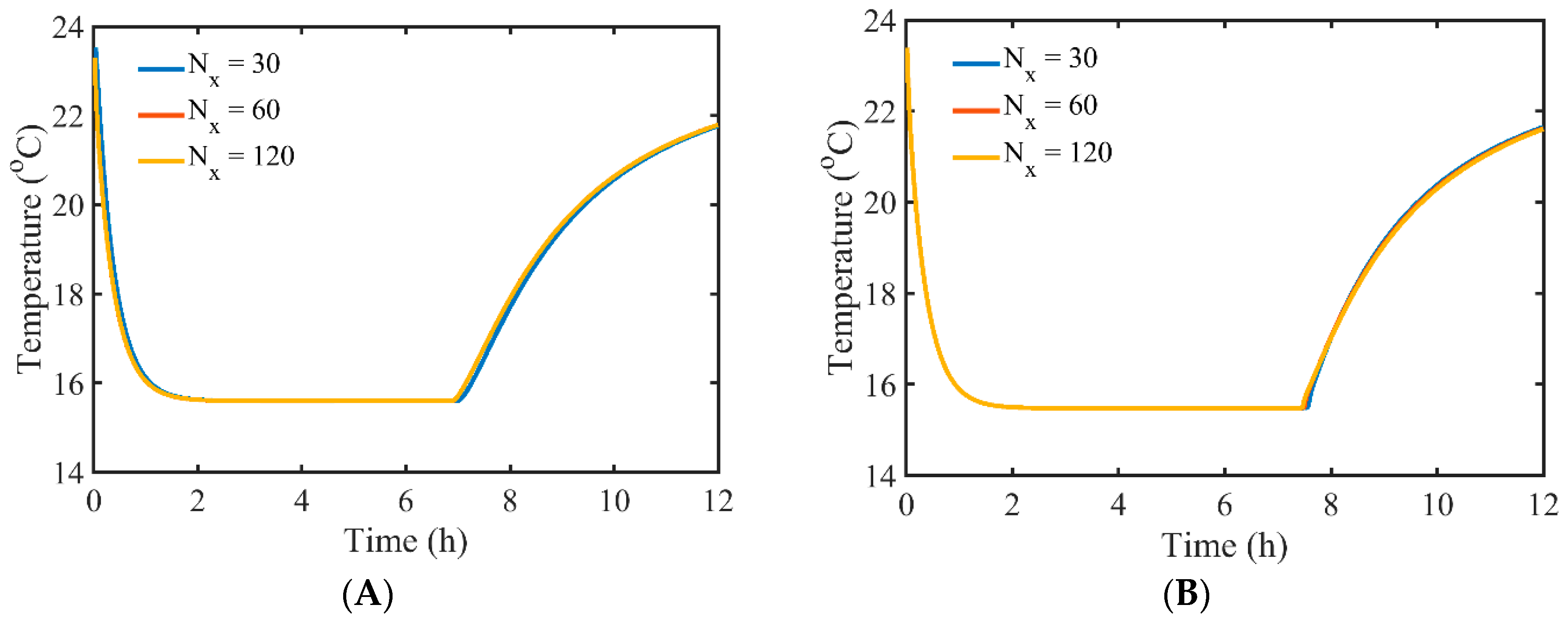
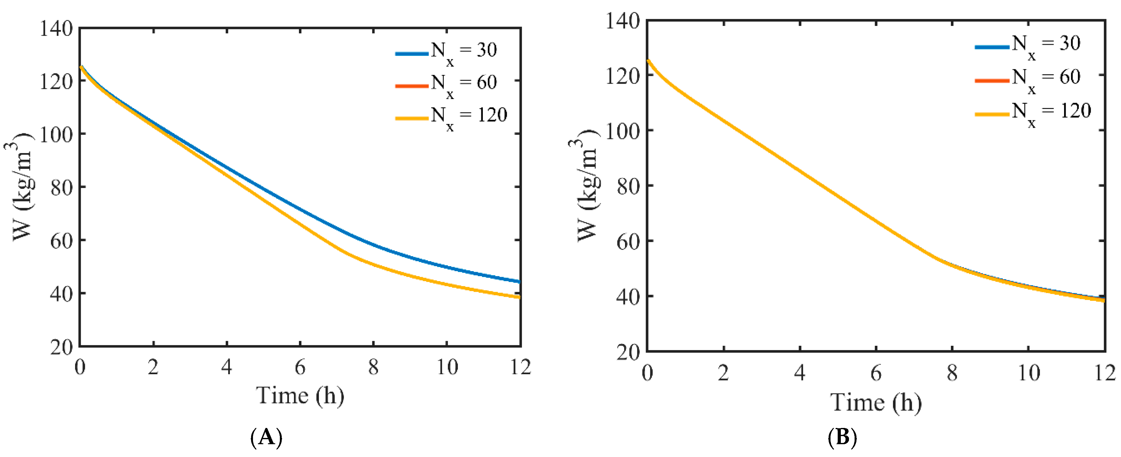
Primarily, the time step size and mesh density sensitivity analysis were carried out separately for both considered numerical models. The main objective of this step was the assessment of the correctness of numerical implementations of the models. Evolutions of the numerically predicted temperature and total moisture content in the brick at 1 cm depth were predicted and compared for three time step sizes (i.e., Δt = 2.5, 5, and 10 s for the non-equilibrium model and Δt = 0.25, 0.5, and 1.0 s for the equilibrium model) and three mesh densities (i.e., Nx = 30, 60, and 120 divisions along the brick thickness for both models). Simulations were carried out for data from Section 3.1 and considered only the convective thermal and mass transfer boundary conditions at the top surface. The thermal radiation was neglected in the sensitivity analysis. For different time step sizes, generally results with very good matching were found and therefore these results are not presented. However, some small discrepancies between predicted temperatures with the equilibrium model for various time steps were observed in the second stage of drying. It was due to stiff coupling of many parameters in a nonlinear way, and the equilibrium condition which had to be fulfilled at the end of each time step. Those conditions were relaxed in the non-equilibrium model. Moreover, during tests of both models it was evident that the equilibrium model required a much shorter time step than the non-equilibrium one. Slight differences were observed for variable grid size. Therefore, Figure 2 and Figure 3 present comparisons of the results obtained for different meshes for both models. Very good conformity of temperatures is visible for both models. However, comparison of moisture content shows that the coarsest mesh (i.e., Nx = 30) is not enough for the non-equilibrium model, and a finer mesh should be used.
Based on these observations the optimum mesh density chosen for subsequent simulations was Nx = 60 for both models, while the time step size was set to Δt = 5 and 0.5 s for the non-equilibrium and equilibrium models, respectively.
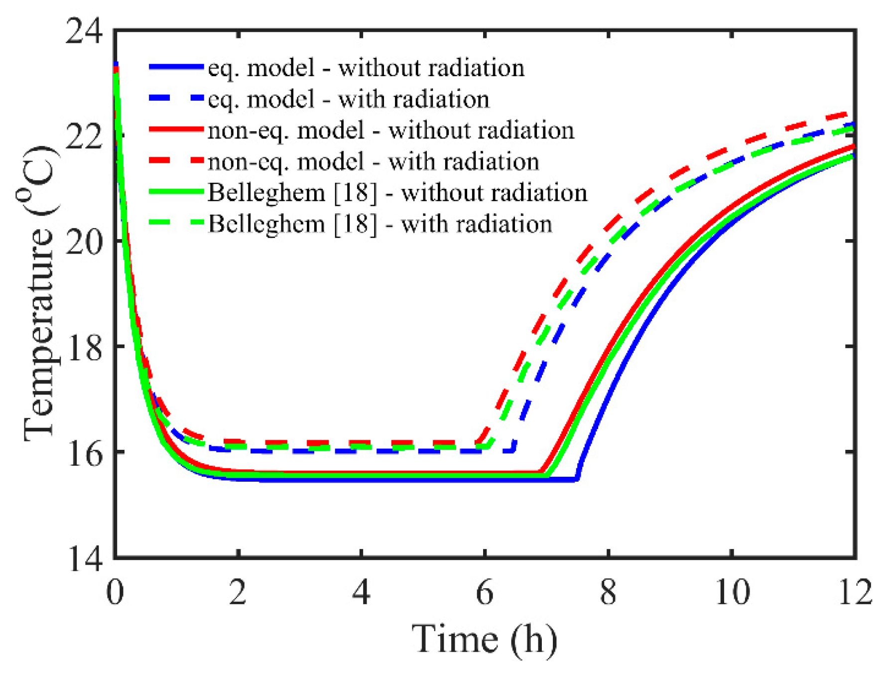
Subsequently, both implementations of the proposed simulation models were verified with the results of numerical simulations performed by Belleghem [18]. These results were obtained by applying the simplified equilibrium model in the 1D geometry. The temperatures inside the brick at 1 cm depth are compared in Figure 4. All simulations reflected the same initial and boundary conditions as well as material properties, as listed in Section 2.4. Two options in boundary conditions were considered, namely with and without radiative heat flux (i.e., the second term on the right-hand side of Equations (31) and (33) was included or neglected, respectively). Presented results reveal good conformity of the temperature predicted with all models. For the adjusted value of the mass transfer coefficient between vapor and water equal to hvl = 2 × 10⁻⁵ s/m, which is required in the non-equilibrium model, very good matching of the predicted temperature variation with both models and the reference one is observed. Some discrepancies are observed for the equilibrium model at the end of the first period of drying. That can be related to the lack of a predefined switching mechanism between the pendular and funicular modes of moisture transfer in the equilibrium model.
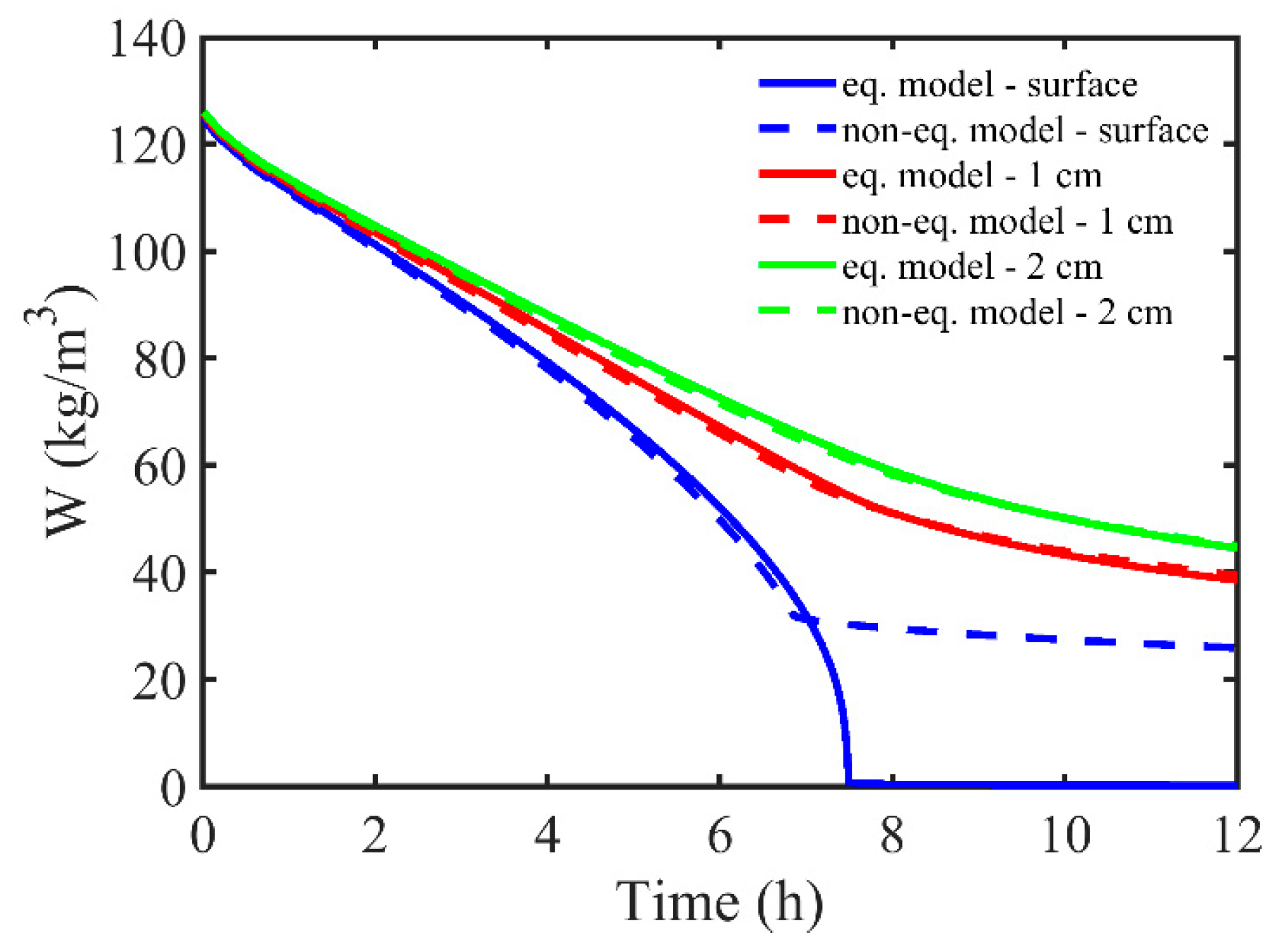
Comparison of volumetric moisture contents predicted with both considered models at the top surface of the brick and inside the building material at a depth of 1 and 2 cm, reveals similar behavior in corresponding points in the first period of drying (see Figure 5). For this case the surface radiative heat flux is neglected. When the total moisture content falls below the smin value, the mode of water transfer is switched from pendular to funicular, so the rate of moisture transfer is considerably reduced. That mechanism is implemented in the non-equilibrium model and neglected in the fully equilibrium model. This results in the difference of the total moisture content observed at the dried top surface in the second stage of drying. The total moisture, predicted with the equilibrium model, continues its diminution to zero, while the content of water predicted with the second model is maintained at a level close to smin.
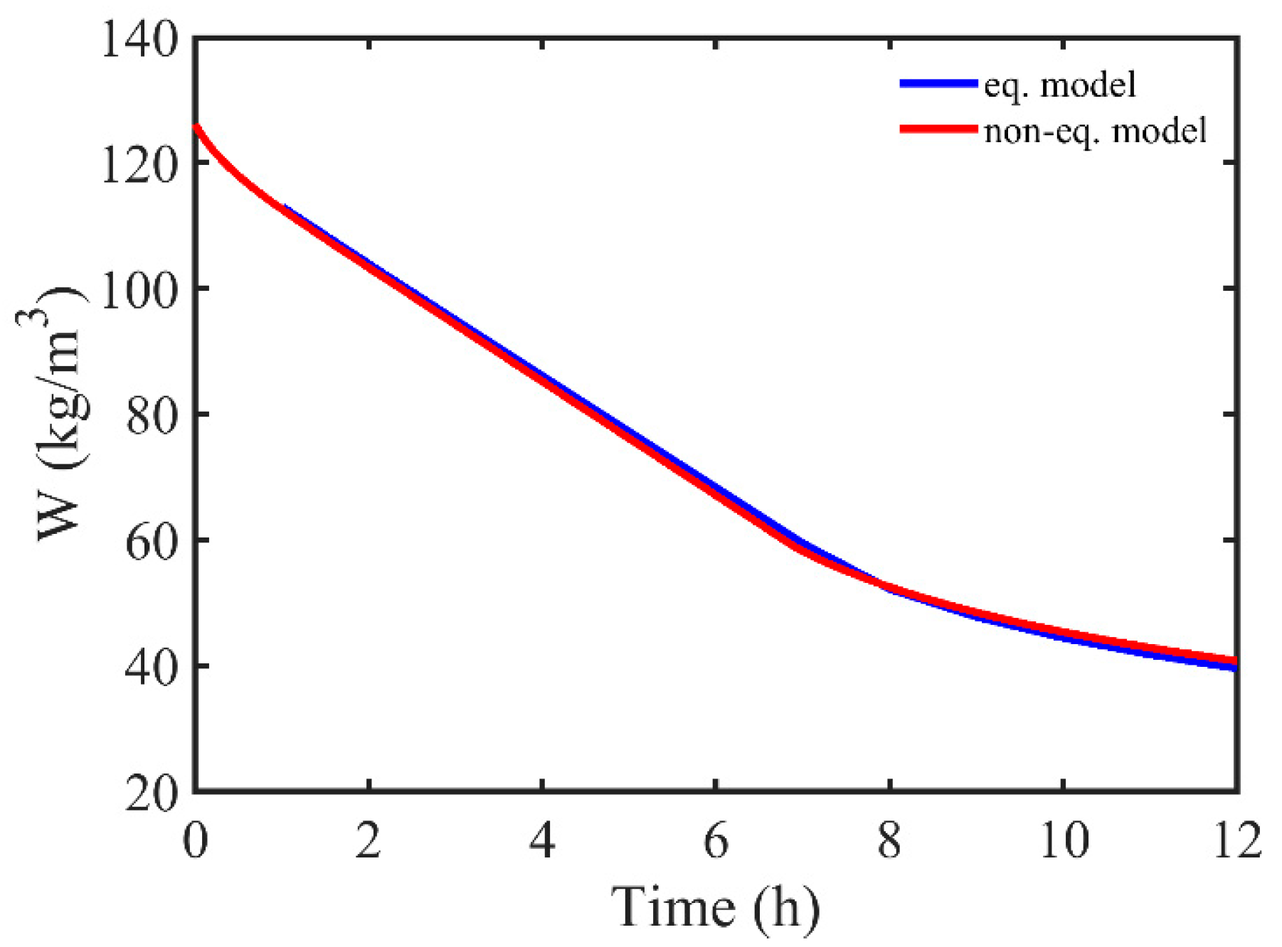
The total moisture contents in a considered wet brick sample with dimensions 0.01 × 0.01 × 0.03 m, predicted with both proposed models was very close in the whole considered time range (see Figure 6). It is expected that the difference between moisture contents will increase after the dry out region enlarges.

5. Conclusions

The paper presents the development and investigation of the non-equilibrium and equilibrium numerical models of concurrent moisture and heat transfer in the wet porous building material. The time step size and mesh density sensitivity analysis reveal that stable and reliable simulations can be performed for moderate time step sizes and mesh densities. Based on the example of a simple, one-dimensional drying problem of uniform material (i.e., brick), both presented models were compared and their implementations verified with reference data [18]. Presented plots of temperature at the three points inside the brick, at the top surface and at the depth of 1 and 2 cm, show good conformity in the first drying stage. At the beginning of the second drying stage some differences appear, but they can be related to slight differences between models, like enforced change in mode of moisture transfer, namely pendular vs. funicular, in the non-equilibrium model. Differences are more pronounced when compared to variation of moisture content at the surface of the brick (Figure 5) in the second drying stage. The origin of this behavior is related to the framework of the non-equilibrium model and its procedure of switching between pendular and funicular mode of moisture transfer. A very good match between predicted total moisture contents with two considered models points out that for relatively short time periods, the simple equilibrium model can be used for preliminary analysis. However, it requires more effort to include the mechanisms of switching between modes of moisture transfer.
The comparison of both models of concurrent moisture and heat transfer shows slight differences between them. Their further development will also be related to their validation. It will be performed with experimental stands which are under development and testing and which are described in recent publications [19,20].

Author Contributions

Conceptualization, M.S., P.F., and P.Ł.; methodology, M.S., P.F., and P.Ł.; software, M.S. and M.W.; validation, M.S., M.W., Ł.C., M.K., K.P., and M.J.; formal analysis, M.S., M.W., P.Ł., Ł.C., M.K., K.P., and M.J.; data curation, M.S., M.W., Ł.C., M.K., K.P., and M.J.; writing—original draft preparation, M.S., P.Ł., and M.W.; writing—review and editing, M.S., P.Ł., and P.F.; visualization, M.S.; supervision, P.Ł.; project administration, P.Ł. and T.S.W.; funding acquisition, P.Ł. and T.S.W. All authors have read and agreed to the published version of the manuscript.

Funding

This work was supported by the European Union within the European Regional Development Fund under project no. POIR.04.01.02-00-0099/16 “Development of innovative technology of drying and moisture sealing of masonry walls, DryWall” granted by the National Centre for Research and Development (Poland).

Conflicts of Interest

The authors declare no conflicts of interest.

References

  1. Whitaker, S. Simultaneous heat, mass, and momentum transfer in porous media: A theory of drying. Adv. Heat Transf. 1977, 13, 119–203. [Google Scholar]
  2. Salagnac, P.; Glouannec, P.; Lecharpentier, D. Numerical modeling of heat and mass transfer in porous medium during combined hot air, infrared and microwaves drying. Int. J. Heat Mass Transf. 2004, 47, 4479–4489. [Google Scholar] [CrossRef]
  3. Van Belleghem, M.; De Backer, L.; Janssens, A.; De Paepe, M. On the modelling of moisture transport in air and capillary porous materials. In Proceedings of the 9th International Conference on Heat Transfer, Fluid Mechanics and Thermodynamics, HEFAT2012, St Julian’s, Malta, 16–18 July 2012. [Google Scholar]
  4. Hagentoft, C.-E.; Kalagasidis, A.S.; Adl-Zarrabi, B.; Roles, S.; Carmeliet, J.; Hens, H.; Grunewald, J.; Funk, M.; Becker, R.; Shamir, D.; et al. Assessment method of numerical prediction models for combined heat, air and moisture transfer in building components. Benchmarks for one-dimensional cases. J. Build. Phys. 2004, 27, 327–352. [Google Scholar] [CrossRef]
  5. Van Belleghem, M.; Steeman, M.; Janssen, H.; Janssens, A.; De Paepe, M. Validation of a coupled heat, vapour and liquid moisture transport model for porous materials implemented in CFD. Build. Environ. 2014, 81, 340–353. [Google Scholar] [CrossRef] [Green Version]
  6. Steeman, H.-J.; Van Belleghem, M.; Janssens, A.; De Paepe, M. Coupled simulation of heat and moisture transport in air and porous materials for the assessment of moisture related damage. Build. Environ. 2009, 44, 2176–2184. [Google Scholar] [CrossRef]
  7. Van Belleghem, M.; Steeman, H.-J.; Steeman, M.; Janssens, A.; De Paepe, M. Sensitivity analysis of CFD coupled non-isothermal heat and moisture modelling. Build. Environ. 2010, 45, 2485–2496. [Google Scholar] [CrossRef] [Green Version]
  8. Janetti, B.M.; Colombo, L.P.M.; Ochs, F.; Feist, W. Effect of evaporation cooling on drying capillary active building materials. Energy Build. 2018, 166, 550–560. [Google Scholar] [CrossRef]
  9. Belleudy, C.; Woloszyn, M.; Chhay, M.; Cosnier, M. A 2D model for coupled heat, air, and moisture transfer through porous media in contact with air channels. Int. J. Heat Mass Transf. 2016, 95, 453–465. [Google Scholar] [CrossRef] [Green Version]
  10. Allam, R.; Issaadi, N.; Belarbi, R.; El-Meligy, M.; Altahrany, A. Hygrothermal behavior for a clay brick wall. Heat Mass Transf. 2018, 54, 1579–1591. [Google Scholar] [CrossRef]
  11. Łapka, P.; Wasik, M.; Furmański, P.; Seredyński, M.; Cieślikiewicz, Ł.; Pietrak, K.; Kubiś, M.; Wiśniewski, T.S.; Jaworski, M. Preliminary mathematical and numerical transient models of convective heating and drying of a brick. MATEC Web Conf. 2018, 240, 01022. [Google Scholar] [CrossRef]
  12. Wasik, M.; Cieślikiewicz, Ł.; Łapka, P.; Furmański, P.; Kubiś, M.; Seredyński, M.; Pietrak, K.; Wiśniewski, T.S.; Jaworski, M. Initial credibility analysis of a numerical model of heat and moisture transfer in porous building materials. AIP Conf. Proc. 2019, 2078, 020106. [Google Scholar]
  13. Cheng, X.; Fan, J. Simulation of heat and moisture transfer with phase change and mobile condensates in fibrous insulation. Int. J. Therm. Sci. 2004, 43, 665–676. [Google Scholar] [CrossRef]
  14. Łapka, P.; Furmański, P. Verification and validation of an advanced model of heat and mass transfer in the protective clothing. Heat Mass Transf. 2018, 54, 2461–2474. [Google Scholar] [CrossRef]
  15. Łapka, P.; Furmański, P.; Wiśniewski, T.S. Assessment of thermal performance of protective garments: The advanced numerical model. Int. J. Numer. Methods Heat Fluid Flow 2017, 27, 1078–1097. [Google Scholar] [CrossRef]
  16. Seredyński, M.; Wasik, M.; Łapka, P.; Furmański, P.; Cieślikiewicz, Ł.; Pietrak, K.; Kubiś, M.; Wiśniewski, T.S.; Jaworski, M. Investigation of the equilibrium and non-equilibrium models of heat and moisture transport in a wet porous building material. E3S Web Conf. 2019, 128, 06008. [Google Scholar] [CrossRef]
  17. Van Belleghem, M.; Ameel, B.; Janssens, A.; De Paepe, M. Modelling heat and moisture transport in porous materials with CFD for building applications. In Proceedings of the 8th International Conference on Heat Transfer, Fluid Mechanics and Thermodynamics, HEFAT2011, Pointe Aux Piments, Mauritius, 11–13 July 2011; pp. 455–463. [Google Scholar]
  18. Van Belleghem, M. Modelling Coupled Heat and Moisture Transfer between Air and Porous Materials for Building Applications. Ph.D. Thesis, Ghent University, Ghent, Belgium, 2013. [Google Scholar]
  19. Cieślikiewicz, Ł.; Łapka, P.; Wasik, M.; Kubiś, M.; Pietrak, K.; Wiśniewski, T.S.; Furmański, P.; Seredyński, M. Development of the experimental stand for investigation of heating and drying phenomena in the porous building materials with one surface of the sample exposed to the flowing air. E3S Web Conf. 2018, 70, 03003. [Google Scholar] [CrossRef]
  20. Cieślikiewicz, Ł.; Wasik, M.; Kubiś, M.; Łapka, P.; Bugaj, M.; Pietrak, K.; Wiśniewski, T.S.; Furmański, P.; Seredyński, M. Development of the experimental stand with centrally located specimen for the investigation of heat and moisture phenomena in porous building materials. Civ. Environ. Eng. Rep. 2019, 29, 53–65. [Google Scholar] [CrossRef] [Green Version]
Figure 1. Schematic of the brick with boundary and initial conditions considered in numerical simulations.
Energies 13 00214 g001
Figure 2. Temporal variations of temperature in the brick at 1 cm depth predicted with a (A) non-equilibrium and (B) equilibrium model for three mesh densities given with number of divisions Nx.
Energies 13 00214 g002
Figure 3. Temporal variations of total moisture content in the brick at 1 cm depth predicted with a (A) non-equilibrium and (B) equilibrium model for three mesh densities given with number of divisions Nx.
Energies 13 00214 g003
Figure 4. Temporal variations of temperature in the brick at 1 cm depth predicted with non-equilibrium and equilibrium models, compared with reference data [18]. Cases involving surface radiative heat flux are denoted with dashed lines, while the results without surface radiative heat flux are denoted with continuous lines.
Energies 13 00214 g004
Figure 5. Comparison of temporal variations of the volumetric moisture content predicted with non-equilibrium and equilibrium models, at the surface and inside the dried brick, at a distance of 1 and 2 cm from the surface.
Energies 13 00214 g005
Figure 6. Comparison of temporal variation of the total moisture content in the brick predicted with the non-equilibrium and equilibrium models.
Energies 13 00214 g006
Table 1. Thermophysical properties assumed during simulations [17].
PropertySymbol and UnitValue
Universal gas constantB (J/kmol/K)8314
Dry air specific heat at constant pressurecp,a (J/kg/K)1005.0
Water specific heatcl (J/kg/K)4192.1
Brick specific heatcs (J/kg/K)840.0
Vapor specific heat at constant pressurecp,v (J/kg/K)1875.2
Water vapor resistance diffusion factorCdry24.79
Average pore diameterdav (m)1.6 × 10⁻⁵
Mass transfer coefficient between vapor and water in the porous mediumhvl (m/s)10−4
Brick thermal conductivityks (W/m/K)1.0
Dry air molecular massMa (kg/kmol)28.86
Vapor molecular massMv (kg/kmol)18
Capillary moisture contentWcap (kg/m3)130.0
Volume fraction of pores (brick porosity)εp0.13
Latent heat of evaporationΔhvl (J/kg)2.5 × 106
Water densityρl (kg/m3)1000.0
Brick densityρs (kg/m3)2087.0