Article

Design and Analysis of a Novel Magnetic Coupler of an In-Wheel Wireless Power Transfer System for Electric Vehicles

Center for Scientific Instrumentation, Korea Basic Science Institute, Daejeon 34133, Korea
*
Author to whom correspondence should be addressed.
Energies 2020, 13(2), 332; https://doi.org/10.3390/en13020332
Submission received: 13 December 2019 / Revised: 6 January 2020 / Accepted: 7 January 2020 / Published: 9 January 2020
(This article belongs to the Special Issue Electrical Machine Design 2020)

Abstract

:
Electric vehicle (EVs), which use an electric motor, are expected to replace internal combustion engine vehicles. However, to date EVs are not highly attractive to consumers due to their unsatisfactory battery charging characteristics and high cost. In particular, the existing conductive charging method makes it more difficult to spread EVs due to the inconvenience of charging and the risk of electric shock. The wireless power transfer (WPT) system can eliminate all of the charging troubles of EVs. However, the WPT systems in existing EVs have large air gaps between the transmitter coil and the receiver coil, posing a hurdle that prevents success. The large air gap cause issues such as a loose coupling, low efficiency, and troublesome electromagnetic compatibility (EMC). An in-wheel WPT system can serve as a solution to address the issues arising due to the large air gap. In this paper, we propose a magnetic coupler structure of an in-wheel WPT system for EV applications. A design of two coils is introduced, in which the transmitter coil and receiver coil are designed based on a design method. Moreover, the pad structure according to the ferromagnetic core geometry is designed and discussed. The aim of this research is to find a suitable configuration of the magnetic coupler for an in-wheel WPT system. The values of the coupling coefficients according the magnetic coupler structure are determined. This paper is expected to provide a good reference for further research, including work on the manufacturing of a prototype.

1. Introduction

Electric vehicles (EVs) are a clean and environmentally friendly alternative to conventional vehicles which utilize an internal combustion engine (ICE). They usually use electric batteries instead of fossil fuel on board to store electric energy for vehicle propulsion. Large-capacity and high-power battery packs are typically required to make EVs operate over satisfactory distances. However, reliable and competitive batteries for EVs are not easy to realize due to the following requirements: (1) an affordable cost, (2) high safety levels, (3) high power density levels, (4) a long cycle lifetime, and (5) a low volume and weight, all of which should be satisfied simultaneously. Lithium-ion batteries are recognized as the most competitive solution, but the energy densities of commercialized lithium-ion battery in EVs are less than 100 Wh/kg at the finished battery pack level [1,2]. On the other hand, gasoline has an energy density of approximately 12,000 Wh/kg, implying that EVs are not as attractive as an alternative to conventional vehicles thus far. Overall, considering maintenance and energy costs, it is expected that the cost will be an extra 1000 USD per year to own and operate an electric vehicle compared to a gasoline-based vehicle [2,3]. In addition, the long charging times of the batteries in EVs also make them unattractive to many consumers. Therefore, charging technology is important for the success of EVs, and it is also important to study and develop more efficient, effective, and convenient charging methods. The charging of EVs can be conducted by either conductive charging or wireless charging. Conductive charging is also called plug-in charging, in which the electric vehicle is connected to a power source through an electric power cable. For conductive charging, problems can arise, such as when the driver forgets to plug in the car and the battery becomes discharged. The power cable for charging on the ground may also introduce a hazard, especially when using a cracked, old cable in poor weather, which may expose the user to an electrical shock. To address these problems, wireless power transfer (WPT) charging systems have been adopted for charging the batteries of EVs either on the road [4] or in parking spaces [5]. By WPT, the charging of EVs becomes more convenient, and the battery capacities of EVs with the WPT system can be reduced to 20% or less compared to EVs which rely on the conductive charging system [2]. The WPT charging system has many advantages, as follows: (1) plugs, cables, and outlets are unnecessary; (2) they use a more friendly charging process; (3) the transfer of energy can be done without worry in any environmental condition; and (4) they require less maintenance and are safer even in inclement weather. Moreover, vandalism is less likely compared to a conductive charging system [6]. However, the WPT charging system has a severe drawback in that the system efficiency decreases significantly when the air gap distance changes or when the coils become laterally misaligned [7,8]. For the WPT charging system, in order to improve the efficiency, it is important to have a high coupling coefficient k and quality factor Q. To realize a high coupling coefficient when the air gap distance increases, a ferromagnetic material can be used [7,8,9,10]. The coupler structure and material have significant effects on the power transfer performance and misalignment tolerance between the transmitter coil and the receiver coil. Recently, various studies of magnetic couplers have been carried out to increase the coupling coefficient in the WPT system. One of these studies involved the use of a ferromagnetic core around a magnetic coupler to optimize the geometry of the ferromagnetic core. A proper ferromagnetic core structure can guide the magnetic fluxes from the transmitter coil to the receiver coil while also improving the coupling coefficient between the two coils [11]. Basic ferromagnetic cores such as the circular, square, and rectangular types have been utilized on the transmitter side as well as the receiver side to reduce leakage of the magnetic field [12]. Although the U-core, E-core, and T-core types offer a higher coupling coefficient, they are not suitable due to their height. Straight ferromagnetic core structures have also been studied to create various shapes and sizes to reduce the leakage inductance and enhance the cost effectiveness. Another important component of the WPT is the coil structure. A variety of planar coil types, such as the rectangular and circular types and various combinations have been studied in relation to WPT design to improve the system performance. Despite the fact that the planar coil has low efficiency compared to the helical and square helix coils, it is suitable for EV charging pads because the pad thickness is thin. The planar circular coil is a well-known and widely used structure in a magnetic coupler for the WPT system because the eddy current is kept to a minimum and the magnetic flux distribution can be controlled by adjusting the diameter. Another well-known case is a rectangular coil, known as a DD pad. For a similar size, a DD pad improves the coupling coefficient, and the charge region can be nearly twice as large as that of the circular type. However, the DD pad has a null point associated with x-direction misalignments [13]. To improve the tolerance against misalignments, a DDQ pad has been studied [13,14]. The DDQ coil is an advanced version of the DD pad. They can produce twice the flux height compared to the circular type. In addition to the merits of the DD pad, it also provides a significant improvement to the lateral misalignment issue. It can be a candidate as a receiver pad due to its ability to acquire both sine and cosine magnetic flux vectors [13,14,15].
Nevertheless, EVs have to address the large air gap problem before they are more widely accepted, as passenger EVs have air-gap distances ranging from 150 to 300 mm. Power transfer efficiency over large misalignment can be enhanced with respect to magnetic coupler and compensation topology [16]. Based on a 500 W prototype WPT system, the power transfer efficiency was achieved above 90% at the air gap of 15 cm and input voltage of 120 VAC [17]. In addition, studies focusing on next-generation road infrastructure, including inductive charging, inductive healing asphalt, and highway-based renewable energy sources are being carried outed [18]. As an alternative to increasing the overall efficiency of wireless charging systems, approaches to reducing losses through improvements in power electronic devices and control techniques have also been studied [19,20,21].
As another solution to this problem, an in-wheel WPT system is studied. Due to the shorter air gap distance and higher coupling coefficient between the transmitter coil and receiver coil, the in-wheel WPT system can be attractive for EVs charging applications. In this paper, a magnetic coupler for the in-wheel WPT system is presented. Two coils for magnetic couplers are considered planar coils because the receiver coils must be located in a narrow space of the wheel. To do this, a design method of the magnetic coupler is devised based on the magnetic coupling coefficient between two coils. Using the design method, a suitable magnetic coupler for an in-wheel WPT system is designed and analyzed. In addition, a WPT system based on the general schematic diagram is described. The relationship between the coupling coefficient and system efficiency in the WPT system are discussed. In order to improve the coupling coefficient, a magnetic coupler including a ferromagnetic core and coil is designed and analyzed by the 3D finite element method. The proposed magnetic coupler structure can be utilized as an efficient substitute of existing wireless charging systems for the electric vehicles which have a large air gap and thus the low coupling coefficient.

2. WPT System for Charging EVs

2.1. Principle of the WPT System for Charging EVs

Table 1 shows the difference between the conductive charging method and the WPT charging method. The main difference between a conductive charging system and a WPT charging method is that the transformer in the former system is replaced by a set of loosely magnetically coupled coils in the latter. The conductive charging method relies on mechanical contact between the EV and charge inlet. The cable can be fed from a charging station. The conductive charging method can be categorized as an AC charging method and a DC charging method. AC conductive charging is carried out via AC charging. On the other hand, DC conductive charging is carried out using a DC charger. It is known as fast DC charging. It uses up to 50 kW, and the battery can be charged in 20 min from empty to 80% full. The WPT charging method uses an electromagnetic (EM) field to transfer energy between two coils. Energy is transmitted through an inductive coupling to the electrical device. This energy is used to charge the batteries.
For EV charging purposes, the WPT consists of many stages, as shown in Figure 1. The charging station side consists of the following: (1) an AC/DC converter which converts AC utility power to DC power using a rectifier with a power factor correction, (2) a DC/high-frequency (HF) inverter which converts DC power to high-frequency AC power to drive the transmitter coil through a compensation network, and (3) a transmitter coil which generates an alternating magnetic field. The EV side consists of (1) a receiver coil which is coupled with an alternating magnetic field generated by the transmitter coil, (2) an AC/DC converter which rectifies the AC utility power to DC power, and (3) a battery pack which is charged by the transmitted electricity energy. In this process, the transferred power and efficiency can be significantly improved by resonating with a compensation network.
Figure 2 shows a schematic diagram of the inductively coupled wireless power transfer system [2]. This diagram is based on the mutual inductance model. The model uses the concepts of induced voltage and reflected voltage to describe the coupling effect between the receiver side and the transmitter side networks. Both the induced voltage and the reflected voltage can be expressed in terms of the mutual inductance, as shown in Figure 2. Winding losses in the receiver coil and transmitter coil are ignored in this model. In addition, the leakage inductance is not modelled separately from the mutual portion. In the mutual inductance model, the reflected voltage is used to represent the effect of the receiver side on the transmitter side. However, the effect of the receiver side is considered together with the transmitter coil in the analysis of the transmitter side network. The reflected voltage is determined by the current flowing within the receiver coil and the mutual inductance between the transmitter coil and the receiver coil. In this diagram, the coils and the compensation network also are retracted to understand the WPT principle. As shown in Figure 2, simplified equation forms of the exchanged complex power, STR and SRT, are expressed as follows,
S ˙ T R = V ¯ T R I ¯ R * = ω M I T I R sin φ T R j ω M I T I R cos φ T R ,
S ˙ R T = V ¯ R T I ¯ T * = ω M I T I R sin φ T R j ω M I T I R cos φ T R ,
where STR and SRT are correspondingly the apparent power exchange between the transmitter coil and the receiver coil. ST and SR are the apparent power that goes into the two coils. LT represents the self-inductance of the transmitter coil and LR represents the self-inductance of the receiver coil. IT and IR are the root mean square values, and φTR is the phase difference between the current in the transmitter coil, ĪT, and the current in the receiver coil, ĪR. The active power transferred from the transmitting side to the receiving side can be expressed as follows:
P T R = ω M I T I R sin φ T R .
Assuming that power is transferred from the transmitter coil to the receiver coil, the maximum power can be transferred when φTR = 90°. The total complex power and reactive power going into the two coil system are expressed as follows:
S ˙ = S ˙ T + S ˙ R = j ω L T I T 2 + L R I R 2 + 2 M I T I R cos φ T R ,
Q = ω ( L T I T 2 + L R I R 2 + 2 M I T I R cos φ T R ) .
As is already known, the efficiency of the magnetic power transfer system can be increased when the ratio between the active power and the reactive power is maximized.
P T R Q = ω M I T I R sin φ T R ω L T I T 2 + L R I R 2 + 2 M I T I R cos φ T R = k 1 c o s 2 φ T R L T L R I T I R + L R L T I R I T + 2 k cos φ T R .
Here, k is the coupling coefficient between LT and LR. The maximum value of the ratio between the active power and reactive power can be achieved when the following conditions are met:
cos φ T R = 2 k L T L R I T I R + L R L T I R I T   , sin φ T R = 1 4 k 2 L T L R I T I R + L R L T I R I T 2 .
For the WPT system, k is close to zero because the two coils are very loosely coupled. Therefore, the transfer power is maximized when the phase difference between ĪT and ĪR is approximately 90°. The degree of coupling affects the compensation network. Considering the series-series (SS) topology, the transmitter coil and receiver coil are connected to the resonance capacitors in series. They are characterized by the self-inductances of the two coils LT and LR, the series-resonance capacitances CT and CR, and the internal resistances RT and RR. When capacitors are added to the transmitter coil and receiver coil side, the system resonates and the power transferred to the load, RL, increases. The output power is expressed as follows:
P o u t = I R 2 R L = ω M I T R R + R L 2 R L = ω k L T L R I T R R + R L 2 R L .
From Equation (8), the following conclusions can be made: under the condition in which the transmitter side current IT is constant, the output power becomes greater as the coupling coefficient increases. In addition, the input power can be expressed as follows:
P i n = I T 2 R T + I R 2 R R + R L .
By defining the quality factor of the two coils, QT = ωLT/RT and QR = ωLR/RR, the transferred efficiency can be expressed as follows:
η = P o u t P i n = R L R R + R L 2 k 2 Q T Q R R R + R R + R L .
The maximum efficiency is achieved at RL/RR = (1 + k2QTQR)1/2; this can be expressed as follows:
η m a x = k 2 Q T Q R 1 + 1 + k 2 Q T Q R 2 .
According to Equation (10), it is clear that the transmission efficiency is only related to the coupling coefficient when the transmitter coil and receiver coil are determined beforehand, and the greater the coupling coefficient, the higher the efficiency. The mutual inductance and coupling factor between the transmitter coil and receiver coil can be changed by changing the design of the magnetic coupler.

2.2. In-Wheel WPT System

Stationary WPT systems for charging EVs already present certain challenges, such as limited power transfer, low efficiency rates, and electromagnetic compatibility (EMC) issues. The power transfer efficiency depends on the gap distance and alignment between the transmitter coil and the receiver coil. Generally, the WPT systems in passenger cars have a gap distance ranging from 150 to 300 mm due to their automotive structure. In order to solve the distance problem in passenger cars, several methods have been suggested [22]. In-wheel WPT systems are future technologies that can be used to charge EVs. The in-wheel WPT topology has advantages with regard to the power transfer efficiency due to the shorter gap distance and the higher coupling coefficient between the transmitter coil and the receiver coil. Figure 3 shows a basic schematic diagram of an in-wheel WPT system. The main grid power is converted to high-frequency AC power and is connected to the transmitter coil through a compensation network. Unlike the conventional WPT system for charging EVs, the receiver coils including the power converter and compensation network are inserted inside a tire of the vehicle. As the tire is always in contact with the road surface, the coupling coefficient and mutual inductance are greater than those in the existing WPT system. The advantages of such an arrangement are that only the particular receiver coil in contact with the transmitter is activated.

2.3. Basic Considerations of the WPT System

In order to realize a user-friendly environment for the EV WPT system, it is important to define the standards of the power level, efficiency, and operating frequency, and safety for the system design. Several task forces of international organizations, such as the International Electro Technical Commission (IEC), the Institute of Electrical and Electronics Engineers (IEEE), and the Society of Automotive Engineers (SAE), have been working on this, and the SAE announced the TIR J2954 WPT standards for PHEVs and EVs with a common operating frequency range between 81.39 and 90 kHz, as shown in Table 2 [2,9]. The WPT system has a lower risk of electric shock than the conductive charging method. However, when charging batteries in EVs by means of WPT, a high-frequency magnetic field between the transmitter coil and receiver coil is generated. A larger air gap between the two coils creates a larger leakage magnetic field. Therefore, the amplitude and frequency of the leakage magnetic field should be regulated to satisfy the safety regulations [2,9]. The guideline released by the International Commission on Non-Ionizing Radiation Protection (ICNIRP) is the most referenced standard for human safety. In ICNIRP 1998, the limit for general public exposure is 6.25 μT within a frequency range of 0.8–150 kHz, which covers most EV WPT systems. The level in the revised ICNIRP 2010 changes from 6.25 to 27 μT.

3. Magnetic Coupler Design

3.1. Design of the Transmitter Coil and Receiver Coil

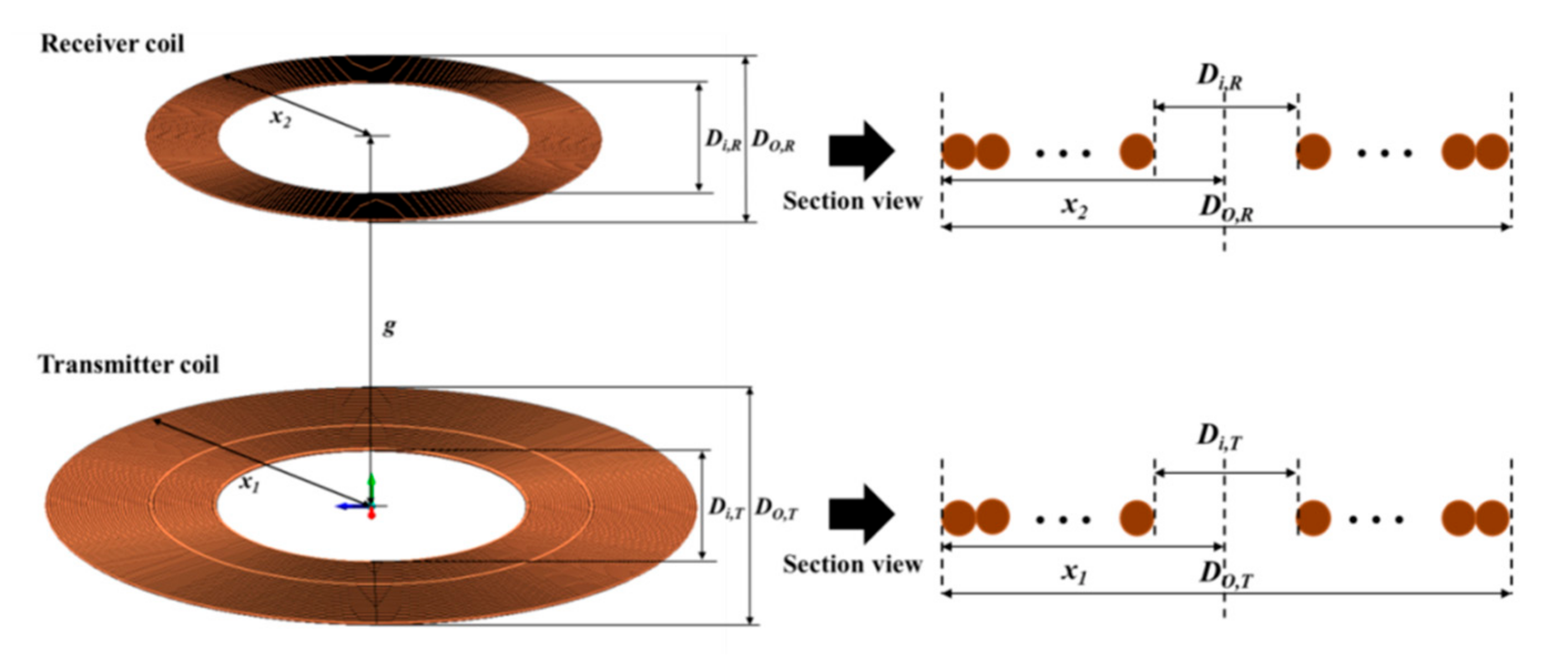
In this paper, the methodology to design two loosely coupled coils for the magnetic coupler is introduced and used based on the planar circular coil geometry, as shown in Figure 4. The planar coil is designed in this paper because the receiver coil must be placed in a narrow space in the wheel. Optimization is achieved based on the coil geometry parameters of the coil shape, outer diameter, inner diameter, and coupling coefficient. Planar circular coils are widely used as a coupler in WPT systems due to their feasible misalignment tolerance. The methods used to calculate the mutual inductance and self-inductance of two coils are available in the literature [23,24]. For planar circular coils, the mutual inductance of two coils with gap distance g can be expressed approximately as follows [25,26],
M μ 0 N T D O , T 2 N R D O , R 2 π 2 D O , R 2 + g 2 3 ,
where NT and NR are the winding turns of the transmitter coil and receiver coil, respectively. The self-inductance of a planar circular coil can be calculated using the equivalent current densities and spiral approximation, as follows:
L = C 1 μ 0 N 2 D O + D i 4 ln C 2 β + C 3 β 2 .
According to the literature [24], the coefficients C1, C2, and C3 are given as 1.00, 2.46, and 0.20, respectively. β, which is the fill ratio, can be expressed as follows:
β = D O D i D O + D i .
To design and optimize the planar circular coils, we use the coupling coefficient between the transmitter coil and receiver coil. The coupling coefficient is calculated as follows:
k = x 1 2 x 2 2 x 1 x 2 x 1 2 + g 2 3 .
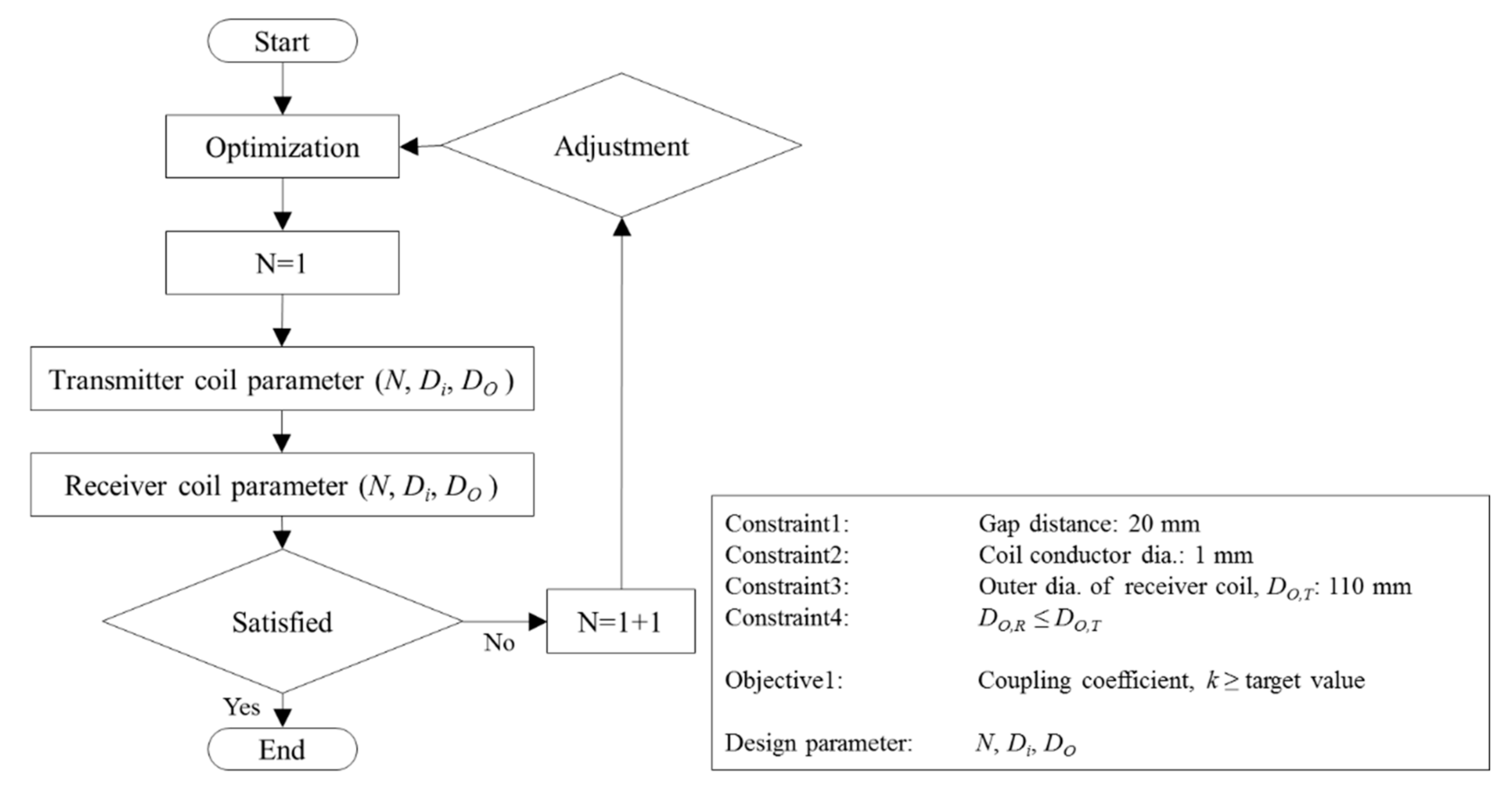
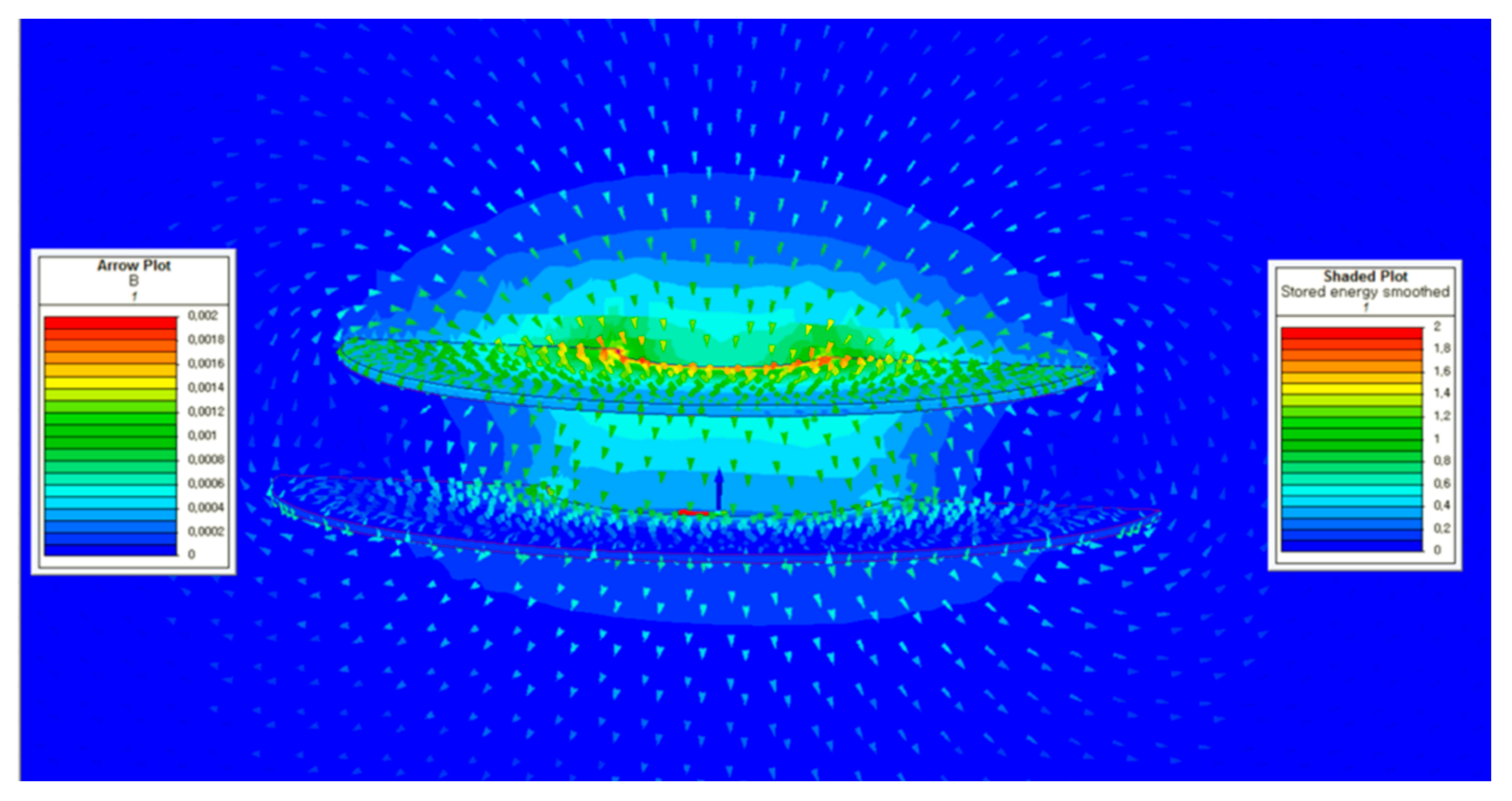
From the equations above, it can be found that the geometry parameters have impacts on the coupling coefficient between the transmitter coil and receiver coil. Based on the aforementioned equations, the planar circular coils were designed. Figure 5 shows the design method of the two coils. The diameter of the receiver coil was limited to 110 mm considering the wheel size. Table 3 shows the design results of the transmitter coil and receiver coil. For the WPT system, a transmitter coil with an inner diameter of 50 mm and outer diameter of 130 mm was selected to determine the coupling coefficient at a resonant frequency for 85 kW. The inner diameter and outer diameter of the receiver coil are 30 and 110 mm, respectively. The corresponding numbers of turns for each coil are 25 and 50. The finite element method (FEM) was used to verify the design results of the coils. The simulations were carried out using the commercialized FEM software MagNet 7.6. The magnetic field and energy distribution in the transmitter coil and receiver coil are illustrated in Figure 6. From Figure 6, it can be found that the transmitter coil and receiver coil are is strongly coupled to each other.

3.2. Design of Pad Structure

Figure 7 shows the overall structure of a magnetic coupler. The transmitter coil (TX coil) is energized by alternating AC power to generate a magnetic field, which in turn induces a voltage in the receiver coil (RX coil). Given that the receiver coil is inserted inside the wheel, it has a coil-only air-core pad structure without a ferromagnetic core. However, the design of the ferromagnetic core is important as it affects the coupling coefficient and inductance of the coils. Therefore, various geometries of the ferromagnetic core for the TX pad can be considered for enhancing the coupling coefficient of the magnetic coupler. Although the EE-core, U-core, pot-core, and double U-core types provide higher coupling coefficients, they are unsuitable for EVs due to their height, as EVs have limited standard clearance levels. In this study, five types of ferromagnetic core geometries, i.e., the circular core, slotted core, bar core, circular bar core, and divided circular core, were analyzed. Six designs including a pad without a ferromagnetic core were simulated using FEM software and compared with respect to the inductance and coupling coefficient. As the receiver coil is located in the wheel, an air core coil without a ferromagnetic core is considered.
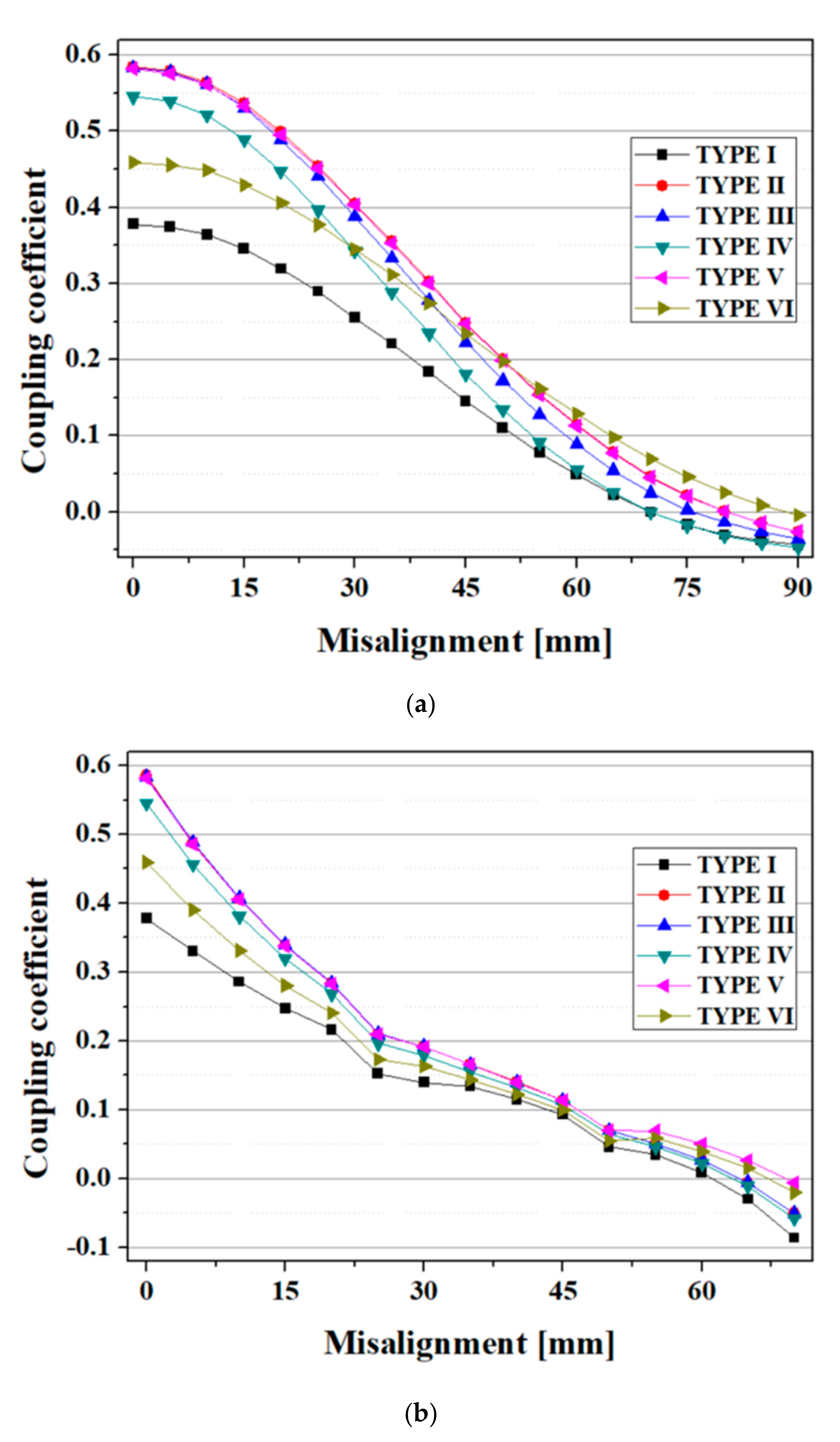
Figure 8 shows the TX pad structure according to the ferromagnetic core geometry. In these figures, the pink color represents the ferromagnetic core, and identical specifications of the TX coil were used to compare the effect of the shape on the ferromagnetic core. As shown in Table 4, the use of a ferromagnetic core not only increases the inductance of the TX coil but also significantly improves the coupling coefficient between the transmitter coil and the receiver coil. In particular, the circular core, slotted core, and circular bar have nearly identical inductances and coupling coefficients. However, the circular bar core type requires approximately 65% of the ferromagnetic core compared to the circular core type. This shows that the circular bar core type is the most economical and effective geometry when considering the coupling coefficient. We also analyzed the misalignment tolerance characteristics of each type of pad. These outcomes are shown in Figure 9. The reduction rate of the coefficients due to a misalignment on the X-axis was relatively small for the divided circular core type; specifically, misalignment of 50 mm or more was found to lead to the highest coefficient among all pad types. However, this is not suitable as a pad type for WPT because it has a coefficient of about 79% compared to the circular bar when the pads are perfectly aligned.

3.3. Circuit Design and Analytical Results

In the WPT system, a compensation network is required to reduce the leakage inductance because the transmitter coil and receiver coil are loosely coupled. To compensate for the leakage inductance, the simplest method is to connect compensation capacitors at the transmitter side and the receiver side. Compensation capacitors can generally be connected in four configurations: the series-series (SS), series-parallel (SP), parallel-series (PS), and parallel-parallel (PP) configurations [27,28,29,30,31]. Source compensation is required to minimize the reactive power on the transmitter side, and a compensation network on the receiver side maximizes the power transfer and efficiency [9]. The types of network topologies can be selected considering the specific application requirements for the WPT system. For the PS and PP configurations, WPT systems are protected such that the transmitter coil does not operate in the absence of the receiver coil. However, a WPT system with either the PS or PP topology is unable to transfer sufficient power in the case of a misalignment between the transmitter coil and the receiver coil. In addition, the value of the capacitance depends on the magnetic coupling and quality factor. For WPT systems with the SP topology, the compensation capacitor on the transmitter side is independent of the mutual inductance and can offer high power transfer rates. However, this depends on the load. The SS topology is most suitable for an EV charging system because the capacitance on the transmitter side is not dependent on the magnetic coupling coefficient and the load. It may also act as a constant current and voltage source, which would be desirable for battery charging [32]. The characteristics of the different compensation types are listed in Table 5.
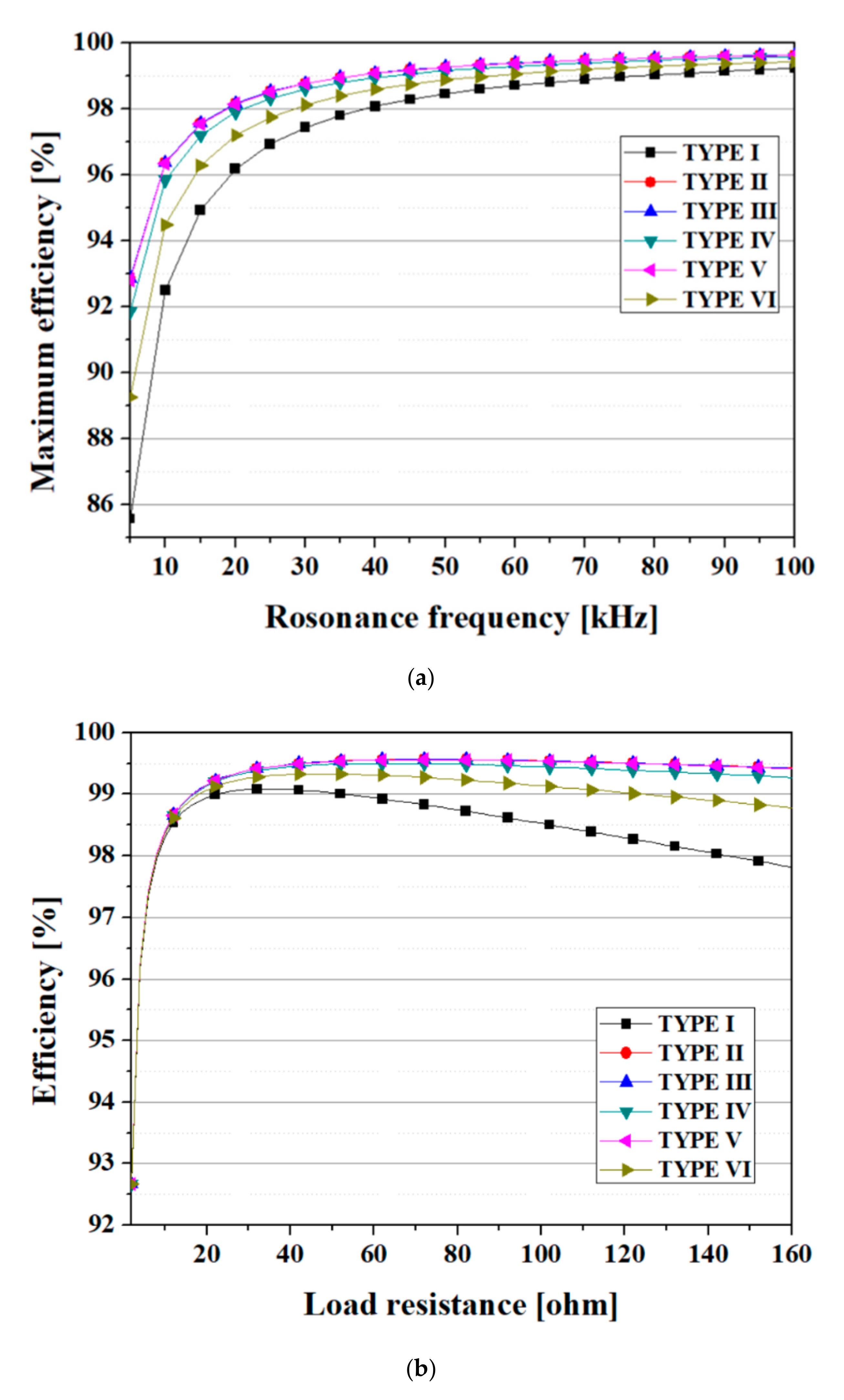
In this table, ω0 is the angular frequency of the WPT system, and k is the coupling coefficient between the transmitter coil and receiver coil. LT and LR are the self-inductance values of the transmitter coil and receiver coil, respectively. In this paper, a WPT circuit based on the SS configuration was built and the characteristics of the designed magnetic coupler were analyzed. The performances capabilities of the magnetic coupler in terms of the coil-to-coil efficiency according to the resonance frequency and load resistance were analyzed. Based on the designed parameters shown in Table 6, the maximum efficiency according to the resonance frequency was evaluated. These results, shown in Figure 10a, demonstrate that the Type II, Type III, and Type V models have superior efficiency characteristics over the range of frequencies used here. Moreover, the power transfer efficiency of the magnetic coupler in the proposed in-wheel WPT system is much higher than that of existing EV charging systems. To determine the impact of the load resistance on the power transfer efficiency, the coil-to-coil power transfer efficiency at a fixed resonance frequency of 85 kHz for each magnetic coupler model was evaluated. These simulation results are presented in Figure 10b. From Figure 10b, we can confirm that the optimal load resistances for the Type II, Type III, and Type IV pads are 70 Ω in all cases. On the other hand, the optimal load resistance for the Type I pad was 40 Ω. The optimized magnetic coupler design has a relatively constant power transfer efficiency value according to the load resistance and resonance frequency.

4. Design Optimization and Analysis

4.1. Optimization of the TX Pad Design Using 3D FEM

Earlier, we analyzed the characteristics of TX pads according to the core type used. As a result, it was confirmed that a TX pad with a circular bar type core had excellent coupling coefficients and transmission efficiency rates, but less ferromagnetic material was used in this core compared to that in the circular type. In this study, we improve the performance of the magnetic coupler by further optimizing the circular bar type core. This optimization process aims to maximize the coupling coefficient within the limits of the ferromagnetic material used. The geometric parameters for shape optimization of the circular bar type core are presented in Figure 11. In this figure, tB and wB refer to the thickness and width of the bar-shaped part, and OD and ID refer to the outer and inner diameters of the circular part, respectively. θ represents the angle between the bars of the circular part of tD. A 3D FEM analysis was carried out to optimize the geometry of the circular bar core for a TX pad. In this analysis, the outer and inner diameters of the circular bar and the angle between the bars were set to 150 and 20 mm, and 45°, respectively. Coupling coefficient values were analyzed by sweeping the dimensions of the circular part ID, OD, and the parameters of tD and wB. In addition, the weight of the ferromagnetic core was calculated in all cases. These calculation results are shown in Figure 12.
In these graphs, the X axis data are valid near the length of the bar-shaped part at 2, 4, 6, and 8 mm. As indicated in the graph, the coupling coefficient is proportional to the amount of ferromagnetic core material used. However, it has been shown that by reducing the thickness of the circular part, the target coupling coefficient can be achieved while significantly reducing the weight of the ferromagnetic core. In particular, when circular bar cores with corresponding ID, OD, ωB, and tD dimensions of 60, 140, 8, and 1 mm are applied, the weight of the ferromagnetic core is only 119.8 g but the coupling coefficient is 0.58409. The weight of the optimized circular bar core is 45% of that of the TYPE II core, indicating that it is possible to develop pads with high coupling coefficients while reducing the weight by optimizing the shape of the circular bar core.
Table 7 shows the design specifications of the magnetic coupler and the design results of the circuit components of the compensation capacitance and load resistance.

4.2. Circuit Simulation by Interworking with an Electromagnetic Analysis

In this study, we analyze the magnetic coupler characteristics, including the compensation network. The analysis was carried out with the circuit modeler in MagNet ver. 7.9. The circuit simulation was carried out in conjunction with an electromagnetic analysis. The load is supplied through a full-wave rectifier and a smoothing capacitor. Unlike the conventional WPT system, the receiver coils in the proposed WPT system are installed inside a tire in a parallel configuration. The series-series compensation topology is selected for the simulation as it has an advantage in that the compensation capacitor is independent of the load condition and the coupling coefficient. In this simulation, an AC/DC converter and DC/HF AC converter on the transmitter side were simplified to high-frequency power sources, and an output voltage regulator was not considered. In addition, by modeling the structure such that a number of receiver coils are arranged in the wheel, a simulation considering the influence of receiver coils other than the receiver coil aligned with the transmitter coils could be carried out. Figure 13a,b shows the full magnetic coupler model and a circuit diagram including the compensation network and full-wave rectifier. In this simulation model, a total of eight receiver coils were placed at 45° intervals, and only one TX pad was considered. As shown in Figure 13b, each of the receiver coils is connected in parallel to the load resistor with a compensation capacitor and a full-wave rectifier circuit. The parameters of all components for the circuit simulation are depicted in Table 7.
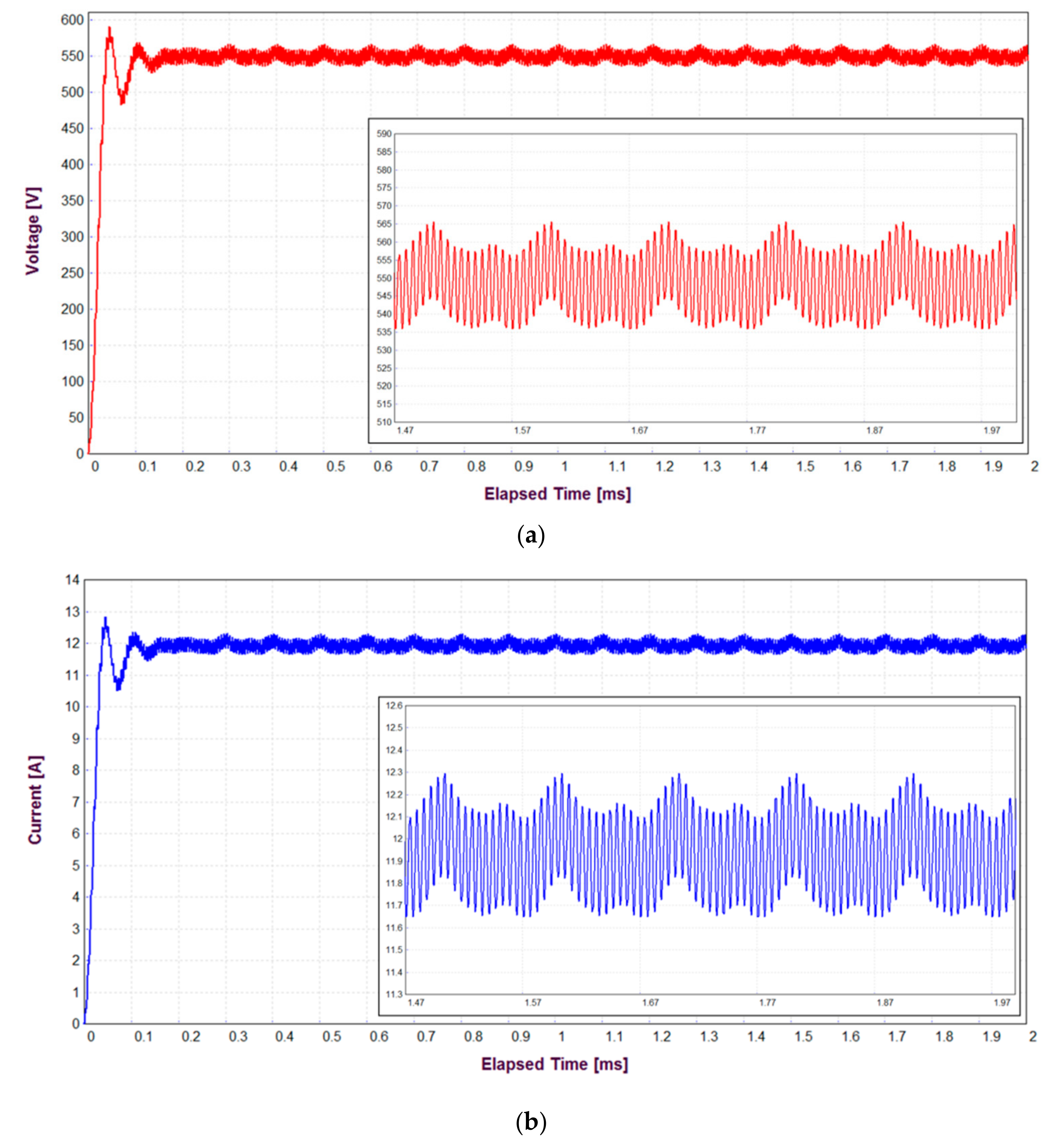
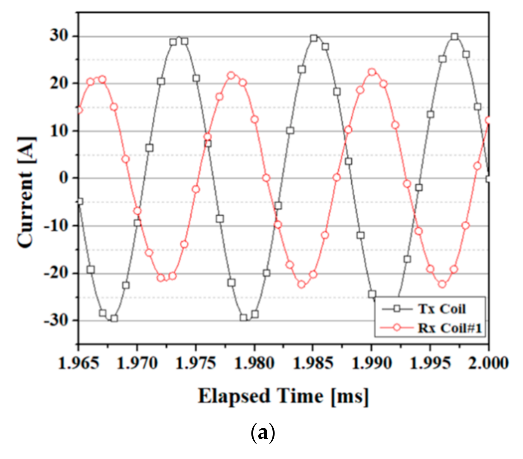
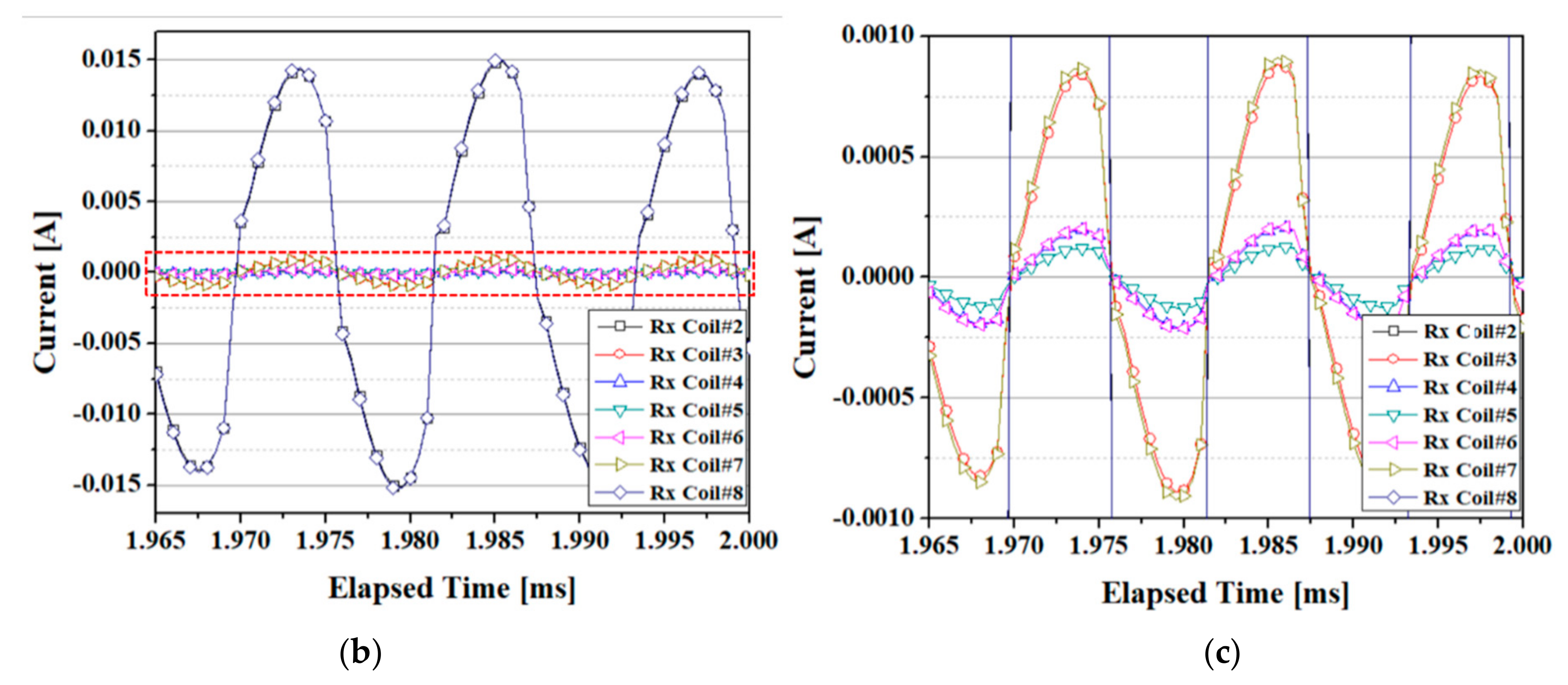
Figure 14 shows the simulation results of the load voltage and load current with the operating frequency set to 85 kHz. According to Figure 14a, a load voltage of 550 V was achieved with a voltage ripple of 2.7%. For the load current, current of 12 A with a ripple of 0.32 A was transferred to the load resistor, as shown Figure 14b. In this simulation, given that the source operates from the first 0 s, the output value differs for each phase up to approximately 0.1 ms due to the transient response component. As the proposed WPT system has multiple receiver coils, other receiver coils are weakly coupled to the transmitter in addition to the aligned receiver coils. Figure 15 shows the current in the transmitter coil and thus the current transferred to each receiver coil. Here, RX coil #1 is a receiver coil that is aligned with the transmitter coil, and the other RX coils represent receiver coils that are not aligned. This result shows that the primary current and secondary current have a phase difference of 90°, with the induced current decreasing rapidly when the receiver coil is misaligned.

5. Discussion

The WPT system for charging EVs already present certain challenges, such as limited power transfer, low efficiency, and EMC issues. The power transfer efficiency decreased with the gap distance and alignment between two coils. In order to address the distance problem, in-wheel WPT systems was studied in this paper. The in-wheel WPT topology has advantages with regard to the power transfer efficiency due to the shorter gap distance and the higher coupling coefficient between the two coils. In order to improve the coupling coefficient, magnetic couplers including ferromagnetic cores and coils were designed and analyzed by 3D finite element method. It has been confirmed that the in-wheel WPT system with the proposed magnetic coupler can be used as an efficient replacement of the existing wireless charging system in terms of power transmission efficiency. The performance of the in-wheel WPT system with the proposed magnetic coupler has been verified through simulations, but there are still issues regarding the integration of the receiver coil into the tire rubber and the transfer of power from the tire to the vehicle body. Further research on the applicability of the proposed magnetic coupler is needed through the fabrication and test of prototype models.

6. Conclusions

The WPT system for charging EVs already present certain challenges, such as limited power transfer, low efficiency, and EMC issues. The power transfer efficiency decreased with the gap distance and alignment between two coils. In order to address the distance problem, in-wheel WPT systems was studied in this paper. The in-wheel WPT topology has advantages with regard to the power transfer efficiency due to the shorter gap distance and the higher coupling coefficient between the two coils. In order to improve the coupling coefficient, magnetic couplers including ferromagnetic cores and coils were designed and analyzed by 3D finite element method. It has been confirmed that the in-wheel WPT system with the proposed magnetic coupler can be used as an efficient replacement of the existing wireless charging system in terms of power transmission efficiency. The performance of the in-wheel WPT system with the proposed magnetic coupler has been verified through simulations, but there are still issues regarding the integration of the receiver coil into the tire rubber and the transfer of power from the tire to the vehicle body. Further research on the applicability of the proposed magnetic coupler is needed through the fabrication and test of prototype models. A magnetic coupler including a planar circular coil and ferromagnetic core was designed for an in-wheel WPT system of an EV. A design method for the planar circular coil was discussed, and the transmitter coil and receiver coil were designed based on the design method. Five ferromagnetic core geometries, in this case a circular core, slotted core, bar core, circular bar core, and divided circular core, were proposed and compared using commercialized FEM software. The simulation results confirm that the circular bar type has the best characteristics in terms of the coupling efficiency and power transfer efficiency while also being economical because it consumes less ferromagnetic core material. At the same time, the circular bar type also showed excellent tolerance against misalignments. This means that the novel circular bar type proposed in this paper has potential as a magnetic coupler for in-wheel WPT systems. Accordingly, shape optimization of the magnetic coupler with the circular bar core on a TX pad was conducted via a 3D FEM analysis. By reducing the thickness of the circular part of the circular bar core, a shape with high coupling coefficients and a reduced weight of the core was designed. Through shape optimization, a magnetic coupler with nearly identical coupling coefficients was designed using 45% of the ferromagnetic material compared to that in the circular core. Compensation capacitors and a load resistor were calculated for a circuit simulation, and the characteristics of the entire coupler system were simulated by combining a circuit simulation and an electromagnetic analysis. This study is expected to serve as a reference for performance improvements of WPT systems for electric vehicles. However, experimental investigations are necessary to verify the proposed magnetic coupler by applying it to an in-wheel WPT system.

Author Contributions

All authors contributed to this work by collaboration. Y.J.H. designed the overall structure of the paper and performed the simulations; J.Y.J. performed the data analysis. All authors have read and agreed to the published version of the manuscript.

Acknowledgments

This work was supported by the Korea Basic Science Institute under Grant D39614.

Conflicts of Interest

The authors declare no conflict of interest.

References

  1. Etacheri, V.; Marom, R.; Elazari, R.; Salitra, G.; Aurbach, D. Challenges in the development of advanced Li-ion batteries: A review. Energy Environ. Sci. 2011, 4, 3243–3262. [Google Scholar] [CrossRef]
  2. Li, S.; Mi, C.C. Wireless Power Transfer for Electric Vehicle Applications. IEEE J. Emerg. Sel. Top. Power Electron. 2014, 3, 4–17. [Google Scholar]
  3. Gerssen-Gondelach, S.J.; Faaij, A.P. Performance of batteries for electric vehicles on short and longer term. J. Power Sources 2012, 212, 111–129. [Google Scholar] [CrossRef]
  4. Tan, L.; Guo, J.; Huang, X.; Liu, H.; Yan, C.; Wang, W. Power Control Strategies of On-Road Charging for Electric Vehicles. Energies 2016, 9, 531. [Google Scholar] [CrossRef]
  5. Kurschner, D.; Rathge, C.; Jumar, U. Design methodology for high efficient inductive power transfer systems with high coil positioning flexibility. IEEE Trans. Ind. Electron. 2011, 60, 372–381. [Google Scholar] [CrossRef]
  6. Budhia, M.; Covic, G.; Boys, J. A new IPT magnetic coupler for electric vehicle charging systems. In Proceedings of the 36th Annual Conference on IEEE Industrial Electronics Society (IECON 2010), Glendale, AZ, USA, 7–10 November 2010. [Google Scholar]
  7. Elnail, K.E.I.; Huang, X.; Xiao, C.; Tan, L.; Haozhe, X. Core Structure and Electromagnetic Field Evaluation in WPT Systems for Charging Electric Vehicles. Energies 2018, 11, 1734. [Google Scholar] [CrossRef] [Green Version]
  8. Imura, T.; Okabe, H.; Hori, Y. Basic experimental study on helical antennas of wireless power transfer for Electric Vehicles by using magnetic resonant couplings. In Proceedings of the 2009 IEEE Vehicle Power and Propulsion Conference (VPPC ’09), Dearborn, MI, USA, 7–10 September 2009. [Google Scholar]
  9. Panchal, C.; Stegen, S.; Lu, J. Review of static and dynamic wireless electric vehicle charging system. Eng. Sci. Technol. Int. J. 2018, 21, 923–937. [Google Scholar] [CrossRef]
  10. Zhang, X. Optimal Design and Analysis of the Stepped Core for Wireless Power Transfer Systems. Mob. Inf. Syst. 2016, 2016, 1–8. [Google Scholar] [CrossRef]
  11. Panchal, C.; Stegen, S.; Lu, J. Simulation of core shape considerations of wireless charging systems for electric vehicles. In Proceedings of the Power and Energy Engineering Conference (APPEEC) IEEE PES Asia-Pacific, Brisbane, QLD, Australia, 15–18 November 2015. [Google Scholar]
  12. Panchal, C.; Lu, J.; Stegen, S. Investigation of magnetic flux distribution of EV wireless charging systems. In Proceedings of the Asia-Pacific International Symposium and Exhibition on Electromagnetic Compatibility: APEMC, Melbourne, Australia, 20–23 May 2013; pp. 380–383. [Google Scholar]
  13. Budhia, M.; Boys, J.T.; Covic, G.A.; Huang, C.-Y. Development of a single-sided flux magnetic coupler for electric vehicle IPT charging systems. IEEE Trans. Ind. Electron. 2011, 60, 318–328. [Google Scholar] [CrossRef]
  14. Covic, G.A.; Kissin, M.L.G.; Kacprzak, D.; Clausen, N.; Hao, H. A bipolar primary pad topology for EV stationary charging and highway power by inductive coupling. In Proceedings of the 2011 IEEE Energy Conversion Congress and Exposition, Phoenix, AZ, USA, 17–22 September 2011; pp. 1832–1838. [Google Scholar]
  15. Zaheer, A.; Kacprzak, D.; Covic, G.A. A bipolar receiver pad in a lumped IPT system for electric vehicle charging applications. In Proceedings of the 2012 IEEE Energy Conversion Congress and Exposition (ECCE), Raleigh, NC, USA, 15–20 September 2012; pp. 283–290. [Google Scholar]
  16. Mahmud, M.; Elmahmoud, W.; Barzegaran, M.R.; Brake, N. Evaluation of Magnetic Pad Sizes and Topologies for Electric Vehicle Charging. IEEE Trans. Magn. 2017, 53, 178–185. [Google Scholar]
  17. Mi, C.C.; Buja, G.; Choi, S.Y.; Rim, C.T. Modern Advances in Wireless Power Transfer Systems for Roadway Powered Electric Vehicles. IEEE Trans. Ind. Elect. 2016, 63, 6533–6545. [Google Scholar] [CrossRef]
  18. Venugopal, P.; Shekhar, A.; Visser, E.; Scheele, N.; Mouli, G.R.C.; Bauer, P.; Silvester, S. Roadway to self-healing highways with integrated wireless electric vehicle charging and sustainable energy harvesting technologies. Appl. Energy 2018, 212, 1226–1239. [Google Scholar] [CrossRef]
  19. Prist, M.; Pallotta, E.; Cicconi, P.; Venturini, A.; Monteriù, A.; Germani, M.; Longhi, S. Energy Saving in Industrial Wireless Power Recharge System: Simulation of a PI-Sliding Mode Control for a Non-Inverting Buck-Boost Converter. In Proceedings of the 2018 IEEE PELS Workshop on Emerging Technologies: Wireless Power Transfer (Wow), Montreal, QC, Canada, 3–7 June 2018. [Google Scholar]
  20. Guo, W.; Bai, H.; Szatmari-Voicu, G.; Taylor, A.; Patterson, J.; Kane, J. A 10 kW high-efficiency LLC resonant DC/DC converter with wide range of output voltage for the battery chargers in plugs-in hybrid electric vehicles. In Proceedings of the 2012 IEEE Transportation Electrification Conference and Expo (ITEC), Dearborn, MI, USA, 18–20 June 2012. [Google Scholar]
  21. Lin, R.; Lin, C.-W. Design criteria for resonant tank of LLC DCDC resonant converter. In Proceedings of the IECON—36th Annual Conference on IEEE Industrial Electronics Society, Glendale, AZ, USA, 7–10 November 2010; pp. 427–432. [Google Scholar]
  22. Panchal, C.; Stegen, S. Static In-wheel Wireless Charging Systems for Electric Vehicle. Int. J. Sci. Technol. Res. 2017, 6, 280–284. [Google Scholar]
  23. Soma, M.; Galbraith, D.C.; White, R.L. Radio-frequency coils in implantable devices: Misalignment analysis and design procedure. IEEE Trans. Biomed. Eng. 1987, 34, 276–282. [Google Scholar] [CrossRef] [PubMed]
  24. Mohan, S.S.; del Mar Hershenson, M.; Boyd, S.P.; Lee, T.H. Simple Accurate Expressions for Planar Spiral Inductances. IEEE J. Solid State Circuits 1999, 34, 1419–1424. [Google Scholar] [CrossRef] [Green Version]
  25. Finkenzeller, K. RFID Handbook: Fundamentals and Applications in Contactless Smart Cards and Identification, 2nd ed.; Wiley: New York, NY, USA, 2003. [Google Scholar]
  26. Chih, W.C.; Kuan, C.H.; Li, J.S.; Sheng, H.H.; Jin, C.C. Wireless powering electronics and spiral coils for implant microsystem toward nanomedicine diagnosis and therapy in free-behavior animal. J. Solid State Electron. 2012, 77, 93–100. [Google Scholar]
  27. Khaligh, A.; Dusmez, S. Comprehensive topological analysis of conductive and inductive charging solutions for plug-in electric vehicles. IEEE Trans. Veh. Technol. 2012, 61, 3475–3484. [Google Scholar] [CrossRef]
  28. Zhang, W.; Wong, S.-C.; Tse, C.K.; Chen, Q. Analysis and comparison of secondary series- and parallel-compensated inductive power transfer systems operating for optimal efficiency and load-independent voltage-transfer ratio. IEEE Trans. Power Electron. 2014, 29, 2979–2990. [Google Scholar] [CrossRef]
  29. Duan, C.; Jiang, C.; Taylor, A.; Bai, K. Design of a zero-voltage switching large-air-gap wireless charger with low electric stress for electric vehicles. IET Power Electron. 2013, 6, 1742–1750. [Google Scholar] [CrossRef]
  30. Boys, J.T.; Covic, G.; Green, A.W. Stability and control of inductively coupled power transfer systems. Proc. IEE Electr. Power Appl. 2000, 147, 37–43. [Google Scholar] [CrossRef]
  31. Chwei-Sen, W.; Covic, G.A.; Stielau, O.H. Power transfer capability and bifurcation phenomena of loosely coupled inductive power transfer systems. IEEE Trans. Ind. Electron. 2004, 51, 148–157. [Google Scholar]
  32. Yilmaz, M.; Krein, P.T. Review of battery charger topologies, charging power levels, and infrastructure for plug-in electric and hybrid vehicles. IEEE Trans. Power Electron. 2013, 28, 2151–2169. [Google Scholar] [CrossRef]
Figure 1. Structure of a typical inductive power transfer system for electric vehicle (EV) charging.
Energies 13 00332 g001
Figure 2. General schematic diagram of the inductively coupled WPT system.
Energies 13 00332 g002
Figure 3. Basic schematic diagram of the in-wheel WPT system.
Energies 13 00332 g003
Figure 4. Geometries of the transmitter coil and receiver coil.
Energies 13 00332 g004
Figure 5. Design method of the transmitter coil and receiver coil.
Energies 13 00332 g005
Figure 6. Magnetic field and magnetic energy distribution of the transmitter coil and receiver coil.
Energies 13 00332 g006
Figure 7. Optimized magnetic coupler shape: (a) ferromagnetic core of the TX pad, and (b) overall magnetic coupler shape including the RX and TX pad.
Energies 13 00332 g007
Figure 8. Pad structure according to the core type: (a) without (W/O) core, (b) circular core, (c), slotted core, (d) bar core, (e) circular bar core, and (f) divided circular core.
Energies 13 00332 g008
Figure 9. Variation of the coupling coefficient and structure according to a misalignment: (a) X-axis misalignment, and (b) Y-axis misalignment.
Energies 13 00332 g009
Figure 10. Power transfer efficiency characteristics: (a) maximum efficiency according to the resonance frequency and (b) efficiency according to the load resistance.
Energies 13 00332 g010
Figure 11. Geometric parameters for shape optimization of the circular bar core.
Energies 13 00332 g011
Figure 12. Coupling coefficient and core weight according to the circular bar core dimensions of the TX pad: (a) coupling coefficient at tD = 1 mm, (b) ferromagnetic core weight at tD = 1 mm, (c) coupling coefficient at tD = 2 mm: (d) ferromagnetic core weight at tD = 2 mm, (e) coupling coefficient at tD = 3 mm, and (f) ferromagnetic core weight at tD = 3 mm.
Energies 13 00332 g012aEnergies 13 00332 g012b
Figure 13. Simulation model: (a) full magnetic coupler in the wheel condition, and (b) circuit diagram including the compensation network and full-wave rectifier.
Energies 13 00332 g013
Figure 14. Simulation results: (a) load voltage waveform, and (b) load current waveform.
Energies 13 00332 g014
Figure 15. Simulation results: (a) transmitter coil current waveform and aligned receiver coil induced current waveform, (b) non-aligned receiver coil induced currents, and (c) zoom-in of red area in (b).
Energies 13 00332 g015aEnergies 13 00332 g015b
Table 1. Differences between conductive charging and wireless power transfer (WPT) charging methods.
Charging MethodConductive ChargingWPT Charging
Cable connectionCable connection is requiredCable connection is not required
Transfer energy typeCurrent in cable is used to couple the EV charging device and the EV EM waves are used couple the EV charging device and the EV
Operating frequency16–100 kHz81.39–90 kHz
Efficiency>90%>90%
Electric shock hazardMedium to highLow to medium
ConvenienceMediumVery high
CostLess expensiveMore expensive
Table 2. Society of Automotive Engineers (SAE) International Standard (J2954) for the PHEV/EV WPT.
ItemWPT Classes
Maximum input power (kW)WPT-1
3.7
WPT-2
7.7
WPT-3
11
WPT-4
22
Minimum efficiency (%)>85%
Operating frequency (kHz)85 (Band: 81.39–90)
Table 3. Design results of the transmitter coil and receiver coil.
ItemTransmitter Coil (TX)Receiver Coil (RX)
Inner diameter (mm)5030
Outer diameter (mm)130110
Turns2550
Inductance (μH)65180
Table 4. Design results of the pad according to the ferromagnetic core geometries.
ParameterCore
Configuration
Core
Thickness
Tx
Self-Inductance
Tx-Rx
Coupling Coefficient
TYPE IW/O2 mm65.4 μH0.37797
TYPE IICircular2 mm121.6 μH0.58530
TYPE IIISlotted2 mm122 μH0.58357
TYPE IVBar2 mm105.6 μH0.54561
TYPE VCircular bar2 mm120.6 μH0.58173
TYPE VIDivided circular2 mm83.2 μH0.45968
Table 5. Characteristics of compensation topologies.
FeaturesSeries-Series
(SS)
Series-Parallel
(SP)
Parallel-Series
(PS)
Parallel-Parallel
(PP)
Power transfer capabilityHighHighLowLow
Power factor at longer distanceSignificantly highHighMediumMedium
Sensitivity to alignmentLess sensitiveLess sensitiveSensitiveHighly sensitive
Total impedance at resonant stateLowLowHighHigh
Frequency tolerance on efficiencyLowHighLowHigh
Capacitor, CT at transmitter side C R L R L T C R L R L T × 1 1 k 2 C R L R L T × 1 Q R 2 k 4 + 1 C R L R L T × 1 k 2 Q R 2 k 4 + 1 k 2
Capacitor, CR at receiver side 1 ω 0 2 L R 1 ω 0 2 L R 1 ω 0 2 L R 1 ω 0 2 L R
Load ω 0 L R Q R ω 0 L R Q R ω 0 L R Q R ω 0 L R Q R
Table 6. Design results of pads according to the ferromagnetic core geometry.
ParameterAir Gap (mm)f0 (kHz)LT (μH)CT (nF)kLR (μH)CR (nF)
TYPE I20 8565.453.60.37797179.919.5
TYPE II2085121.628.80.58530179.919.5
TYPE III208512228.70.58357179.919.5
TYPE IV2085105.633.20.54561179.919.5
TYPE V2085120.629.10.58173179.919.5
TYPE VI208583.242.10.45968179.919.5
Table 7. Design results of the magnetic coupler and compensation circuit.
ItemValue
TransmitterCoilI.D./O.D.50 mm/130 mm
Winding turns25
Circular bar coreID60 mm
OD140 mm
tD1 mm
tB2 mm
wB8 mm
Weight119.8 g
Inductance118.8 μH
Compensation capacitance29.5 nF
ReceiverCoilI.D./O.D.30 mm/110 mm
Winding turns50
Inductance180 μH
Compensation capacitance19.5 nF
Coupling coefficient0.58409
Load resistance46 Ω