Article

Design Analysis of Micro Gas Turbines in Closed Cycles

by
Krzysztof Kosowski
* and
Marian Piwowarski
*
Faculty of Mechanical Engineering, Gdansk University of Technology, Gabriela Narutowicza Street 11/12, 80-233 Gdansk, Poland
*
Authors to whom correspondence should be addressed.
Energies 2020, 13(21), 5790; https://doi.org/10.3390/en13215790
Submission received: 4 October 2020 / Revised: 31 October 2020 / Accepted: 2 November 2020 / Published: 5 November 2020
(This article belongs to the Special Issue Small-Scale Energy Systems with Gas Turbines and Heat Pumps)

Abstract

:
The problems faced by designers of micro-turbines are connected with a very small volume flow rate of working media which leads to small blade heights and a high rotor speed. In the case of gas turbines this limitation can be overcome by the application of a closed cycle with very low pressure at the compressor inlet (lower than atmospheric pressure). In this way we may apply a micro gas turbine unit of accepted efficiency to work in a similar range of temperatures and the same pressure ratios, but in the range of smaller pressure values and smaller mass flow rate. Thus, we can obtain a gas turbine of a very small output but of the efficiency typical of gas turbines with a much higher power. In this paper, the results of the thermodynamic calculations of the turbine cycles are discussed and the designed gas turbine flow parts are presented. Suggestions of the design solutions of micro gas turbines for different values of power output are proposed. This new approach to gas turbine arrangement makes it possible to build a gas turbine unit of a very small output and a high efficiency. The calculations of cycle and gas turbine design were performed for different cycle parameters and different working media (air, nitrogen, hydrogen, helium, xenon and carbon dioxide).

1. Introduction

Power plants with gas microturbines are intensively developed nowadays [1], including those operating in polygeneration systems [2,3]. It seems that microturbine technology will be frequently applied in distributed power generation [4,5]. This technology has greatly improved its efficiency thanks to the use of electric generators with rare earth magnets [6,7,8]. On the other hand, efforts are being made to improve the efficiency, durability and cost reduction of the energy systems based on fuel cells [9,10,11] or photovoltaic cells [12,13].
The development of technology has made it possible to develop Brayton closed cycles, in which various working media can be used [14]. The closed gas turbine cycle was patented in 1935 by J. Ackeret and C. Keller. The first closed cycle with 2 MW oil-fired gas turbine (AK-36) was built in Switzerland in 1939, followed by another six units built in Switzerland and Germany [15,16]. Gas power plants with a closed cycle and air as a working medium showed a very high reliability at that time. The most representative was the 50 MW helium plant installed in Oberhausen which operated from 1975 to 1987 in Germany [17,18]. Work on the progress of these power plants has been suspended due to the dynamic development of gas turbines in open cycles [19]. Currently, these technologies have become of interest again because of the possibility of their application in nuclear power plants [20,21] or in those power stations that use solar energy [22]. In the systems with nuclear reactors, closed cycles with air, CO2 [23] or helium [24] are considered for application. Other working media, such as nitrogen or xenon, are also taken into account [25]. Supercritical CO2 power plants are used which allow to obtain a very good efficiency at low temperatures at the turbine inlet [26,27].
In order to increase the efficiency, closed cycle power plants are modified [28]. The parameters of the working medium are optimized [29] and regenerators [30] and intercoolers [31] can sometimes be applied.
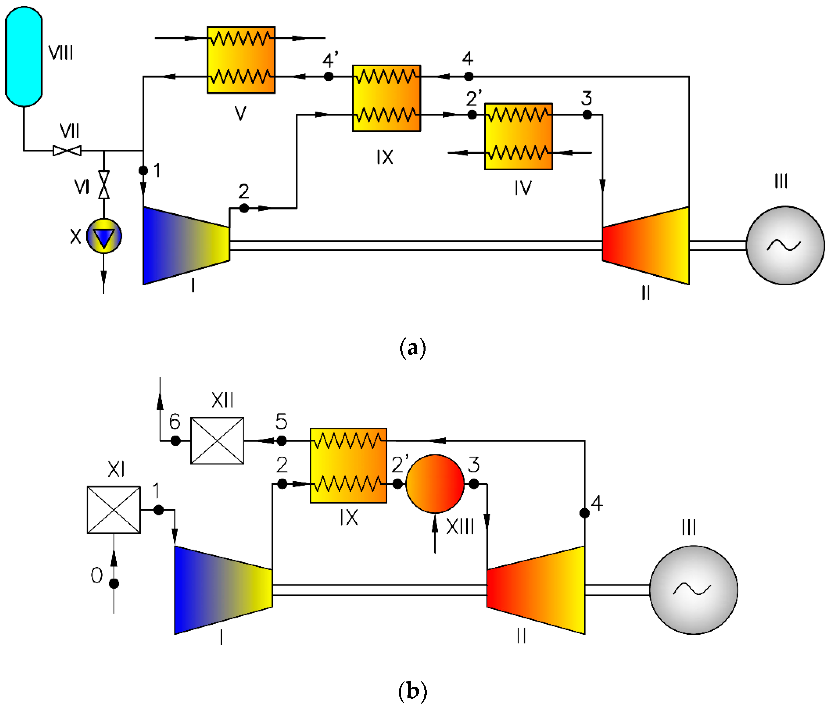
A scheme of a simple closed gas turbine cycle is shown in Figure 1a, [32]. The working medium is compressed in the compressor I and then heated in the high temperature heat exchanger IV. Next, hot gases expand in turbine II, which drives electric generator III. After expansion, the temperature of gases decreases in low temperature heat exchanger V and they return to the compressor inlet. In comparison to the simple open cycle, Figure 1b, the combustion chamber is replaced by an externally fired gas heater IV (source of upper temperature), while the gas cooling heat exchanger V replaces the atmosphere as the source of lower temperature.
The closed cycle presented in Figure 1a is the simplest possible. More complex cycles contain regeneration, intercooling and reheating systems. The advantages of power plants working in a closed cycle are given below [32]:
-
possibility of burning different kinds of fuel (due to an external combustion chamber),
-
possibility of using the high pressure of the medium (higher pressure means higher medium density, on the one hand leading to smaller dimensions for the same output, on the other hand enabling the building of high output units),
-
possibility of applying different gases as a working medium, in particular gases with better heat exchange parameters and a high value of specific heat cp, remarkably reducing dimensions and increasing specific turbine output.
The main disadvantage of the closed gas turbine cycle is the necessity of introducing additional heat exchangers, especially the high temperature exchanger IV, which is large in size, heavy and costly (compared with a typical combustion chamber). The low temperature cooler V also increases the dimensions of the whole power plant. Gas turbines can be used in closed cycles with high-temperature gas-cooled reactors (HTGR) and in this form they constitute a competitive alternative to light water nuclear power plants.
As a rule, the main advantage of the closed cycle is the possibility of using the high pressure of the working medium and increasing the output of the power unit. The interpretation of the thermodynamic processes for different power outputs is presented in Figure 2. We propose a reverse situation: a closed cycle with a very low value of pressure at the compressor inlet (lower than the atmospheric pressure). In this way we may apply a gas turbine unit of a relatively high efficiency in the same range of temperatures and the same pressure ratios but in the range of smaller pressure values and a smaller mass flow rate. Thus, we can obtain a gas turbine of a very small output but of the efficiency typical of gas turbines of much higher power.
The most important innovation is that instead of a classical approach to closed gas turbines, a new feature of a closed cycle was shown and applied to design a micro gas turbine of a higher efficiency than the typical engines of the same power. These types of power plants have not been discussed in literature so far.
By applying the proposed method, the micro gas turbines can achieve an efficiency which is higher than that of typical open cycle turbines. For example, the performed analyses have clearly proved that it is possible to design a 10 kW gas micro turbine of a relatively high efficiency of about 31.2% (which is a very competitive value).

2. Modelling

The design analysis was carried out for the turbine closed cycle with a regenerator. The schema of the cycle and its interpretation in a temperature-entropy diagram are shown in Figure 3a and Figure 4, respectively, while the open cycle with a regenerator is presented in Figure 3b.
The classical approach to designing gas turbine plants usually leads to a situation where the decrease in the assumed output results in lower values of volume flow rate, lower diameters, lower blade heights, a drop in the efficiency and an increase in the rotor speed. These relations are illustrated by the comparison of the examples of micro turbines of 50 kW, 35 kW and 10 kW.
The flow parts of the compressors (Figure 5) and the turbines (Figure 6) have been designed by CFD (Computational Fluid Dynamics) codes while the heat exchangers (regenerators) and the combustion chambers have been calculated with the use of standard thermodynamics relations, occasionally applying the iteration method. The symbols and subscripts used in the paper are presented in Table 1 and Table 2.
Calculations were made with the use of standard formulae (the indices refer to the points marked in the diagram, Figure 1 and Figure 3):
-
heat delivered to the working media (heater IV):
q 1 = ( i 0 i 6 ) ,
-
heat rejected with the water cooling the heater (V):
q 2 = ( i 4 i 1 ) ,
-
turbine work obtained by CFD calculations,
-
compressor work obtained by CFD calculations.
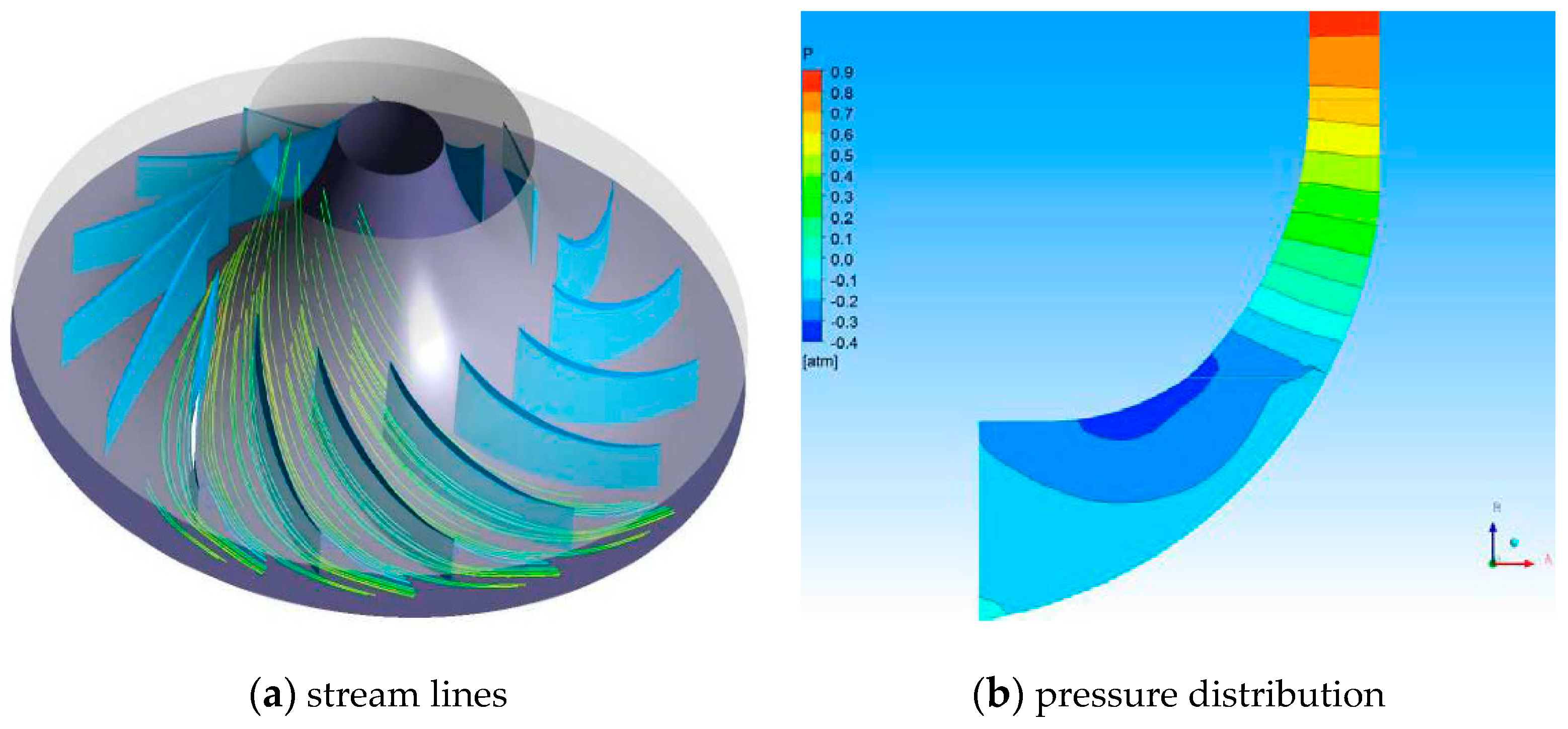
The flow parts of the turbine and the compressor have been calculated using ANSYS software. The examples of the distribution of the calculated parameters in flow channels (velocity lines and pressure) are presented in Figure 5 and Figure 6 for the compressor stage and the turbine stage, respectively. The numerical mesh for the compressor flow channel consisted of about 54,000 nodes and 48,600 elements. The example of a mesh at 50% blade span is shown in Figure 7a. Numerical meshes for the turbine nozzles and the rotor blades are shown in Figure 7b,c, respectively. Numerical stationary calculations have been performed assuming the multiple reference method (MRF method), the k-ω shear stress transport (SST) turbulence model and the circumferential symmetry. Air as a working medium has been treated as a viscous and compressible gas.
The energy efficiency is defined as the ratio of the net electric power obtained related to the heat flux supplied to the system and given by the equation:
η e l = N e l Q ˙ D .
Depending on the variant, the net electric power is the power NT obtained in the turbine, diminished by the power NK consumed to drive the compressor and by the losses in the system (generator efficiency ηG, mechanical efficiency ηm, leakage losses).
The effectiveness of the regenerator is defined as the ratio of the actual temperature increase in the exchanger to the maximum possible increase and is determined by the formula:
σ R = Δ T real Δ T max = T 2 T 2 T 4 T 2 .
The assumed values of the efficiences or the losses of particular engine elements are presented in Table 3 [32,33,34]. The chosen numbers can be considered as good average values but not the highest.
The calculations have been performed for temperature T3 in front of the turbine equal to T3 = 850 °C (within the range typical of gas turbines of very small output). The parameters of the working media have been determined using REFPROP [35] media library.

3. Results and Discussion

The gas turbine units and the whole power plants of 10 kW, 35 kW and 50 kW were designed. In Figure 8 the example of the turbine power plant is shown, while the main parameters of the particular variants are presented in Table 4 and in Figure 9, the compressor rotors and Figure 10, the turbine discs.
The highest efficiency, equal to about 32%, was obtained for 50 kW turbine, while the lowest (about 23.6%) for 10 kW unit. The 50 kW turbine has the highest diameter, the longest blades and the lowest rotor speed (55,000 rpm), while the 10 kW turbine has the lowest diameter, the smallest blades and the highest rotor speed (120,000 rpm). Thus, the dimensions and the operating parameters vary remarkably for the turbines of different output (Table 4 and Figure 9 and Figure 10). The calculations and the designs have confirmed a well-known statement that the lower the turbine power the more difficult it is to build a turbine of good efficiency.
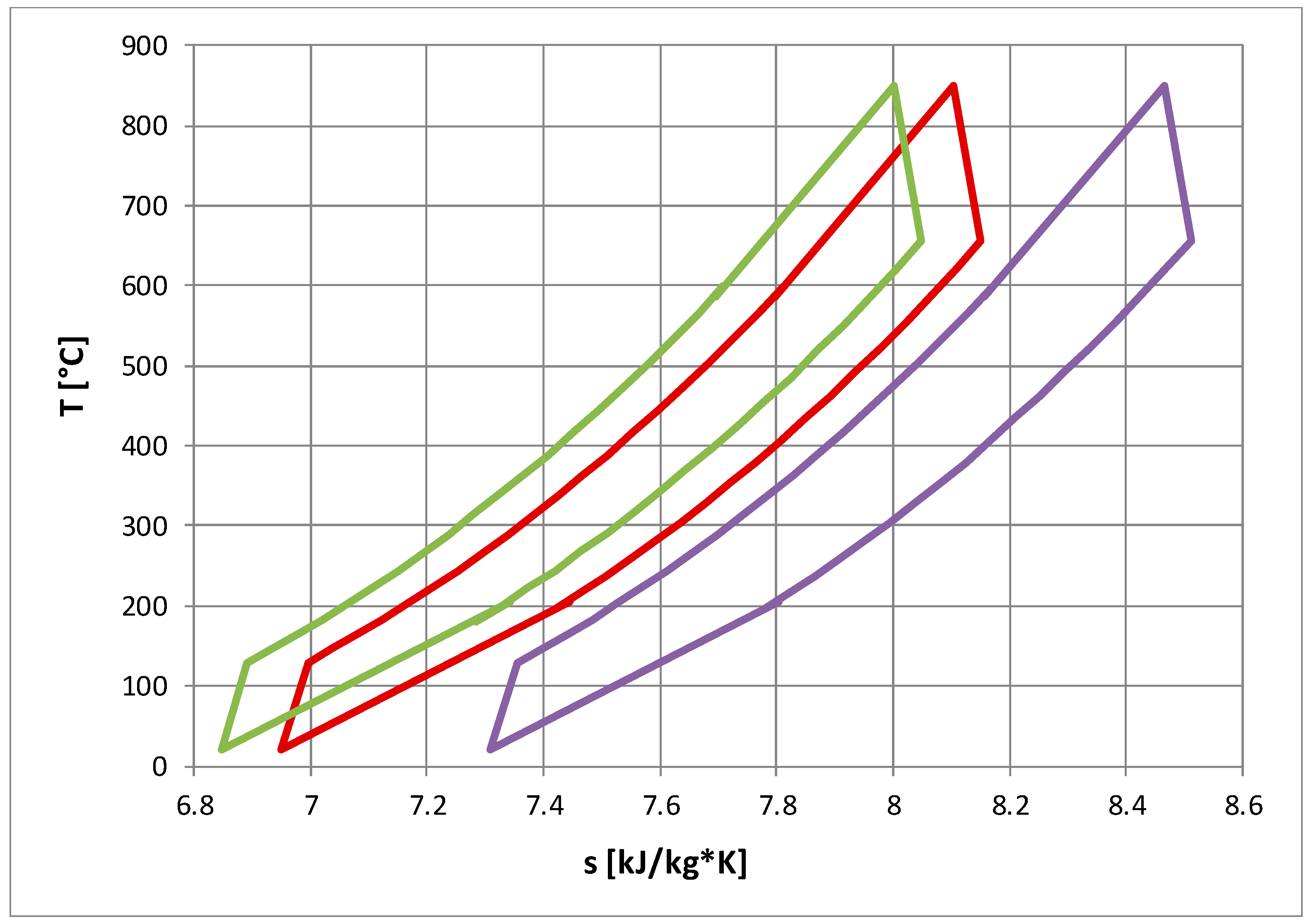
The situation described above illustrates a typical approach to the designing of gas turbines, however, thanks to the application of a closed cycle with a very low value of pressure at the compressor inlet (lower than the atmospheric pressure), it is possible to obtain a gas turbine of a very small output but with the efficiency typical of gas turbines of much higher power. We may choose a micro gas turbine unit of an accepted design and efficiency to work in the same range of temperatures and the same pressure ratios, but with smaller pressure values and a smaller mass flow rate. Let us consider the gas turbine unit of 50 kW presented above. Applying this engine in a closed cycle and changing the value of pressure at the compressor inlet, it is possible to obtain lower output with the same efficiency. The results are shown in Table 4 and the interpretations of the cycles are presented in Figure 11.
As a result of the calculations, we may conclude that it is enough to apply a highly efficient gas turbine in a closed cycle and reduce the pressure at the compressor inlet in order to obtain a power plant of a smaller output but the same high efficiency. In the presented example of the 50 kW turbine with a reduction of pressure in front of the compressor from 0.1 MPa to 0.07 MPa or to 0.02 MPa allows us to receive 35 kW and 10 kW, respectively. All the variants have the same efficiency (31.26%), identical rotor speed (55,000 rpm), the same pressure ratio (2.6) and the same upper temperature (T3 = 850 °C) (Table 4). It seems that the proposed method enables us to obtain a gas turbine of a very small output but high efficiency and a relatively small rotor speed. Thus, a new feature of a closed gas turbine cycle was shown and applied to design a micro turbine of a relatively high efficiency. This conclusion is one of the most important innovations that has not been described in literature so far.
Closed gas turbine cycles make it possible to apply different working media, especially the gases with better heat exchange parameters and a high value of specific heat cp, thus remarkably reducing the dimensions and, at the same time, increasing specific turbine output. The calculations of the closed cycles have been performed for six different fluids: air, nitrogen, helium, carbon dioxide, hydrogen and xenon and for various values of the temperature in front of the turbine (800–1000 °C, the range typical of gas turbines of very small output). The parameters of the working media have been determined using REFPROP [35] media library. In Figure 12 the overall efficiency of the cycles with a regenerator and the upper temperature T3 = 850 °C are presented as the function of the compressor pressure ratio. The engine efficiency reaches over 36% for air, nitrogen and hydrogen. It is slightly smaller for helium and xenon and about 2% lower for carbon dioxide. The optimum pressure ratio varies from less than 2 for helium and xenon to about 3.7 for carbon dioxide.

4. Conclusions

The authors have presented the results of the design analysis of micro turbines proving that it is possible to increase the efficiency of gas turbines of small output. By the application of a closed cycle with a very low value of pressure at the compressor inlet a gas turbine of a very small output is obtained which has the efficiency typical of gas turbines of a much higher power. We may choose a well-designed micro gas turbine unit of high efficiency and apply it to work in the same range of temperatures and the same pressure ratios but with smaller pressure values and a smaller mass flow rate. Thus, a gas turbine of a very small output can operate with the efficiency typical of gas turbines of a much higher power. In the presented example the efficiency of the 10 kW turbine has increased from 23.6% to 31.2%.
The performed analyses have clearly proved that applying closed gas turbine cycles is possible when we use different working media. The cycle and the gas turbine design calculations were performed for different cycle parameters and different working media (air, nitrogen, hydrogen, helium, xenon and carbon dioxide). Their better heat exchange parameters and a higher value of specific heat cp can reduce the engine dimensions and increase the specific turbine output.

Author Contributions

Conceptualization, K.K. and M.P.; methodology, K.K. and M.P.; formal analysis, K.K. and M.P.; data curation, K.K. and M.P.; writing—original draft preparation, K.K. and M.P.; writing—review and editing, K.K. and M.P.; supervision, K.K. and M.P.; funding acquisition, K.K. and M.P. All authors have read and agreed to the published version of the manuscript.

Funding

This research received financial support from The National Centre for Research and Development (Poland), project: Development of integrated technologies in the production of fuel and energy from biomass, agricultural and other waste.

Acknowledgments

The authors would like to thank Robert Stępień and Wojciech Włodarski from Gdansk University of Technology for their help in performing the ANSYS calculations and preparing the figures.

Conflicts of Interest

The authors declare no conflict of interest. The funders had no role in the design of the study; in the collection, analyses or interpretation of data; in the writing of the manuscript; and in the decision to publish the results.

References

  1. Kosowski, K.; Włodarski, W.; Piwowarski, M.; Stępień, R. Performance characteristics of a micro-turbine. Adv. Vib. Eng. 2014, 2, 341–350. [Google Scholar]
  2. Stępniak, D.; Piwowarski, M. Analyzing selection of low-temperature medium for cogeneration micro power plant. Pol. J. Environ. Stud. 2014, 23, 1417–1421. [Google Scholar]
  3. Thu, K.; Saha, B.B.; Chua, K.; Bui, T.D. Thermodynamic analysis on the part-load performance of a microturbine system for micro/mini-CHP applications. Appl. Energy 2016, 178, 600–608. [Google Scholar] [CrossRef]
  4. Kosowski, K.; Stępień, R.; Włodarski, W.; Piwowarski, M.; Hirt, Ł. Partial admission stages of high efficiency for a microturbine. J. Vib. Eng. Technol. 2014, 2, 441–448. [Google Scholar]
  5. Soares, C. Microturbines: Applications for Distributed Energy Systems, 1st ed.; Elsevier’s Science & Technology: Oxford, UK, 2007; ISBN 978-0750684699. [Google Scholar]
  6. Włodarski, W. Experimental investigations and simulations of the microturbine unit with permanent magnet generator. Energy 2018, 158, 59–71. [Google Scholar] [CrossRef]
  7. Włodarski, W. Control of a vapour microturbine set in cogeneration applications. ISA Trans. 2019, 94, 276–293. [Google Scholar] [CrossRef]
  8. Włodarski, W. A model development and experimental verification for a vapour microturbine with a permanent magnet synchronous generator. Appl. Energy 2019, 252, 113430. [Google Scholar] [CrossRef]
  9. Saadabadi, S.A.; Thattai, A.T.; Fan, L.; Lindeboom, R.E.; Spanjers, H.; Aravind, P. Solid Oxide Fuel Cells fuelled with biogas: Potential and constraints. Renew. Energy 2019, 134, 194–214. [Google Scholar] [CrossRef]
  10. Kwaśniewski, T.; Piwowarski, M. Design analysis of hybrid gas turbine‒fuel cell power plant in stationary and marine applications. Pol. Marit. Res. 2020, 2, 107–119. [Google Scholar] [CrossRef]
  11. Cozzolino, R.; Lombardi, L.; Tribioli, L. Use of biogas from biowaste in a solid oxide fuel cell stack: Application to an off-grid power plant. Renew. Energy 2017, 111, 781–791. [Google Scholar] [CrossRef]
  12. Herrando, M.; Pantaleo, A.M.; Wang, K.; Markides, C.N. Solar combined cooling, heating and power systems based on hybrid PVT, PV or solar-thermal collectors for building applications. Renew. Energy 2019, 143, 637–647. [Google Scholar] [CrossRef]
  13. Hsu, P.-C.; Huang, B.J.; Wu, P.-H.; Wu, W.-H.; Lee, M.-J.; Yeh, J.-F.; Wang, Y.-H.; Tsai, J.-H.; Li, K.; Lee, K.-Y. Long-term Energy Generation Efficiency of Solar PV System for Self-consumption. Energy Procedia 2017, 141, 91–95. [Google Scholar] [CrossRef]
  14. Kunniyoor, V.; Singh, P.; Nadella, K. Value of closed-cycle gas turbines with design assessment. Appl. Energy 2020, 269, 114950. [Google Scholar] [CrossRef]
  15. Bammert, K.; Rurik, J.; Griepentrog, H. Highlights and Future Development of Closed-Cycle Gas Turbines. J. Eng. Power 1974, 96, 342–348. [Google Scholar] [CrossRef]
  16. Kehlhofer, R.; Kunze, N.; Lehmann, J.; Schüller, K.H. Gasturbinenkraftwerke, Kombikraftwerke, Heizkraftwerke und Industriekraftwerke Resch, Handbuchreihe Energie; Band 7; Technischer Verlag Resch: München, Germany, 1992; ISBN 3-88585-094-X. [Google Scholar]
  17. McDonald, C.F.; Boland, C.R. The Nuclear Closed-Cycle Gas Turbine (HTGR-GT)—Dry Cooled Commercial Power Plant Studies. J. Eng. Power 1981, 103, 89–100. [Google Scholar] [CrossRef] [Green Version]
  18. Wolf, J.; Perkavec, M. Neuste Entwicklungen im Gasturbinenbau—Gasturbinen in Energetischen Anlagen; VDI Berichte: Leverkusen, Deutchland, 1998. [Google Scholar]
  19. Ahn, Y.; Lee, J.I. Study of various Brayton cycle designs for small modular sodium-cooled fast reactor. Nucl. Eng. Des. 2014, 276, 128–141. [Google Scholar] [CrossRef]
  20. Bae, S.J.; Lee, J.; Ahn, Y.; Lee, J.I. Preliminary studies of compact Brayton cycle performance for Small Modular High Temperature Gas-cooled Reactor system. Ann. Nucl. Energy 2015, 75, 11–19. [Google Scholar] [CrossRef]
  21. Malik, A.; Zheng, Q.; Qureshi, S.R.; Zaidi, A.A. Effect of helium xenon as working fluid on the compressor of power conversion unit of closed Brayton cycle HTGR power plant. Int. J. Hydrogen Energy 2020, 45, 10119–10129. [Google Scholar] [CrossRef]
  22. Stein, W.H.; Buck, R. Advanced power cycles for concentrated solar power. Sol. Energy 2017, 152, 91–105. [Google Scholar] [CrossRef] [Green Version]
  23. Kizilkan, O.; Khanmohammadi, S.; Saadat-Targhi, M. Solar based CO2 power cycle employing thermoelectric generator and absorption refrigeration: Thermodynamic assessment and multi-objective optimization. Energy Convers. Manag. 2019, 200, 112072. [Google Scholar] [CrossRef]
  24. McDonald, C.F. Helium turbomachinery operating experience from gas turbine power plants and test facilities. Appl. Therm. Eng. 2012, 44, 108–142. [Google Scholar] [CrossRef]
  25. Tournier, J.-M.P.; El-Genk, M.S. Properties of noble gases and binary mixtures for closed Brayton Cycle applications. Energy Convers. Manag. 2008, 49, 469–492. [Google Scholar] [CrossRef]
  26. Liese, E.; Albright, J.; Zitney, S.A. Startup, shutdown, and load-following simulations of a 10 MWe supercritical CO2 recompression closed Brayton cycle. Appl. Energy 2020, 277, 115628. [Google Scholar] [CrossRef]
  27. Ma, Y.; Liu, M.; Yan, J.; Liu, J. Performance investigation of a novel closed Brayton cycle using supercritical CO2-based mixture as working fluid integrated with a LiBr absorption chiller. Appl. Therm. Eng. 2018, 141, 531–547. [Google Scholar] [CrossRef]
  28. Olumayegun, O.; Wang, M.; Kelsall, G. Closed-cycle gas turbine for power generation: A state-of-the-art review. Fuel 2016, 180, 694–717. [Google Scholar] [CrossRef]
  29. Liu, H.; Chi, Z.; Zang, S. Optimization of a closed Brayton cycle for space power systems. Appl. Therm. Eng. 2020, 179, 115611. [Google Scholar] [CrossRef]
  30. Sadatsakkak, S.A.; Ahmadi, M.H.; Ahmadi, M.A. Thermodynamic and thermo-economic analysis and optimization of an irreversible regenerative closed Brayton cycle. Energy Convers. Manag. 2015, 94, 124–129. [Google Scholar] [CrossRef]
  31. Miao, H.; Wang, Z.; Niu, Y. Key issues and cooling performance comparison of different closed Brayton cycle based cooling systems for scramjet. Appl. Therm. Eng. 2020, 179, 115751. [Google Scholar] [CrossRef]
  32. Kosowski, K. Steam and Gas Turbines with the Examples of Alstom Technology; Alstom: Saint-Ouen, France, 2007; ISBN 978-83-925959-3-9. [Google Scholar]
  33. Mikielewicz, D.; Kosowski, K.; Tucki, K.; Piwowarski, M.; Stępień, R.; Orynycz, O.; Włodarski, W. Gas Turbine Cycle with External Combustion Chamber for Prosumer and Distributed Energy Systems. Energies 2019, 12, 3501. [Google Scholar] [CrossRef] [Green Version]
  34. Mikielewicz, D.; Kosowski, K.; Tucki, K.; Piwowarski, M.; Stępień, R.; Orynycz, O.; Włodarski, W. Influence of Different Biofuels on the Efficiency of Gas Turbine Cycles for Prosumer and Distributed Energy Power Plants. Energies 2019, 12, 3173. [Google Scholar] [CrossRef] [Green Version]
  35. Lemmon, E.; Huber, M.; McLinden, M. NIST Standard Reference Database 23: Reference Fluid Thermodynamic and Transport Properties-REFPROP. In Standard Reference Data Program; Version 9.0 edition; National Institute of Standards and Technology: Gaithersburg, MD, USA, 2010. [Google Scholar]
Figure 1. Scheme of a gas turbine simple closed cycle (a) and a simple open cycle (b); where: I—compressor, II—turbine, III—generator, IV—high temperature exchanger, V—low temperature exchanger, VI and VII—valves, VIII—gas expansion tank, IX—combustion chamber, X—filter, XI—silencer and XII—ejector.
Energies 13 05790 g001
Figure 2. Example of thermodynamic processes interpretation for different power output (gas turbine simple closed cycle).
Energies 13 05790 g002
Figure 3. Scheme of a gas turbine closed cycle with regenerator (a) and schema of an open cycle with a regenerator (b); where: I—compressor, II—turbine, III—generator, IV—high temperature exchanger, V—low temperature exchanger, VI and VII—valves, VIII—gas expansion tank, IX—regenerator, X—ejector, XI—filter, XII—silencer and XIII—combustion chamber.
Energies 13 05790 g003
Figure 4. Example of thermodynamic processes interpretation for gas turbine (open or closed) cycle with regenerator.
Energies 13 05790 g004
Figure 5. Examples of numerical calculations of compressor flow part: stream lines (a) and pressure distribution in a channel (b).
Energies 13 05790 g005
Figure 6. Examples of numerical calculations of turbine rotor channels: stream lines (a) and pressure distribution (b).
Energies 13 05790 g006
Figure 7. Examples of numerical meshes: compressor channel (a), turbine nozzle (b) and turbine rotor blade (c).
Energies 13 05790 g007
Figure 8. Example of a designed gas turbine power plant: turbine rotor (a), turbine unit (b) and power plant (c).
Energies 13 05790 g008aEnergies 13 05790 g008b
Figure 9. Designed compressor rotors for the gas turbine of 50 kW (a), 35 kW (b) and 10 kW (c).
Energies 13 05790 g009
Figure 10. Designed turbine rotors for the gas turbine of 50 kW (a), 35 kW (b) and 10 kW (c).
Energies 13 05790 g010
Figure 11. Interpretation of gas turbine closed cycles for different power output, where 50 kW—green line, 35 kW—red line and 10 kW—purple line.
Energies 13 05790 g011
Figure 12. Efficiency of the cycles with regenerator as the function of the compressor pressure ratio.
Energies 13 05790 g012
Table 1. List of symbols.
SymbolDescriptionUnit
Ddiameter[m]
ienthalpy of unit mass[kJ/kg]
lblade height[m]
mmass flow rate[kg/s]
MaMach number[-]
nrotational speed[rpm]
Npower[kW]
ppressure[Pa]
ReReynolds number[-]
Qheat flux[kW]
sentropy of unit mass[kJ/kg·K]
Ttemperature[°C]
Vvolumetric flow rate[m3/s]
ηefficiency[-]
α1angle of absolute velocity vector at nozzle exit[°]
α2angle of absolute velocity vector at blade exit[°]
β1angle of relative velocity vector at nozzle exit[°]
β2angle of relative velocity vector at blade exit[°]
Δgradient[-]
Пcompressor pressure ratio[-]
σregenerator efficiency[-]
Table 2. List of used subscripts.
SymbolDescription
Ggenerator
Kcompressor
elelectrical
mmechanical
nleakage
Rregenerator
Tturbine
Ddelivered
1, 2, …numbers on diagrams
Table 3. Assumptions for the design analysis of turbine variants.
DescriptionUnitValue
compressor efficiency[-]from CFD calculations of particular variant
turbine efficiency[-]from CFD calculations of particular variant
mechanical efficiency[-]0.980
leakage losses[-]0.02
generator efficiency[-]0.900
sum of pressure losses[-]0.06
Table 4. The main parameters of the gas turbine sets.
DescriptionUnitValue
Ne[kW]50.035.010.0
П[-]2.62.42.2
p1[MPa]0.10000.10000.1000
T3[°C]850.00850.00850.00
ηREG[-]0.870.870.88
mpow[kg/s]0.51810.47220.1681
ηel[-]0.312590.269110.23665
n[rpm]55,00065,000120,000
D1K[m]0.07900.06730.0367
D2K[m]0.14370.12230.0667
ηK[-]0.830.780.75
Maw2[-]0.290.330.32
Mac2[-]0.740.730.73
Rec3[-]326,161.41327,239.87335,282.76
α1[°]90.0090.0090.00
β1[°]30.0030.0030.00
β2[°]44.0145.1241.53
α2[°]15.5115.9812.92
l1K[m]0.01590.01390.0750
l2K[m]0.00850.00700.0043
DT[m]0.14770.11510.0688
l1T[m]0.01700.01640.0120
l2T[m]0.01800.17200.0124
ηT[-]0.830.790.76
Mac1[-]0.710.730.74
Maw2[-]0.740.790.79
α1[°]17.5017.0011.00
β1[°]83.3270.7985.11
β2[°]21.7821.2614.73
α2[°]87.0473.9689.93
Publisher’s Note: MDPI stays neutral with regard to jurisdictional claims in published maps and institutional affiliations.