Safe and Efficient Coal Mining Below the Goaf: A Case Study

School of Energy and Mining Engineering, China University of Mining and Technology (Beijing), Beijing 100083, China
*
Author to whom correspondence should be addressed.
Energies 2020, 13(4), 864; https://doi.org/10.3390/en13040864
Submission received: 7 January 2020
/
Revised: 11 February 2020
/
Accepted: 13 February 2020
/
Published: 16 February 2020
Abstract
:Mining at the fully mechanized working face below the goaf of the short-distance coal seam is influenced by the upper goaf. To address this problem, methods such as theoretical analyses, numerical simulation, and on-site measurement are used to study the strata behavior characteristics of the Ningxia Lingxin Coal Mine 051508 working face in this study. The roof weighting intervals of the working faces below the goaf and the non-goaf are obtained via theoretical calculations. The stoping processes of the working faces below the goaf and the non-goaf are simulated with FLAC3D to obtain the distribution law of the bearing pressure and plastic zones before the working face. Based on the statistical analysis of the measured working resistance of the supports and its distribution, the roof weighting interval of the working face mining below the goaf is obtained. The results show that the roof weighting interval and the advanced abutment pressure during mining at the working face below the goaf are smaller than those below the non-goaf, providing a reasonable theoretical basis for mining below the goaf, and having important significance for safe and efficient mining.

1. Introduction
Coal resources are vital in national energy security, the consumption and production of coal account for 63% and 77% of the primary energy, respectively [1]. With the long-term high-intensity mining of coal resources, coal resources with simple conditions in eastern China are becoming increasingly scarce. The issue of mining short-distance coal seams is widely distributed in China and has been receiving increasing attention to preserve China’s energy supply. The recoverable reserves of short-distance coal seams account for approximately 43% of China’s total coal resources, and over 65% of the mining areas in China have short-distance coal seams [2]. The common mining methods for short-distance coal seams are upward and downward mining. Downward mining is the most widely used mining method, i.e., mining from top to bottom [3]. When the short-distance coal seam undergoes downward mining, the stoping of the upper layer coal causes damage to the floor to a certain depth, and the mining of the lower layer coal is adversely affected by the roof cracking and the abutment pressure caused by the goaf and coal pillars. The law of strata behaviors will be different from the mining of a single coal seam [4]. Therefore, the analysis of the effects of the goaf resulting from the upper coal seam mining on the law of strata behaviors in the lower coal seam will be of great significance for the safe and efficient production of short-distance coal seams.
At present, scholars have studied and summarized the mining of short-distance coal seams and the mining below the goaf. Based on the damage depth formed in the floor because of mining-induced stress, Yingda defined short-distance coal seam groups and established a structural model control theory for them [5]. Ming studied the evolution and influence of stress concentration and rock fracture in deep multi-coal seam mining, established a mechanical model using the infinitesimal strain theory, and analyzed the failure of the middle layer at the vertical and horizontal directions [6]. Cheng et al. studied the control of surrounding rocks during stoping of the protected layers under the protective layers using methods such as similar simulation and numerical simulation; they obtained the relationship between the effects of the support methods on the roadway wall rock and structural evolution and the advancing speed of the working face and the failure height of the wall rock and overburden rock [7,8]. Singh et al. determined the stability and support requirements for the short-distance continuous coal seam mining by establishing a numerical model, analyzing and summarizing the prediction formula for the interval between layers [9,10,11]. Qiwei et al. studied the overburden rock structure and crack evolution of the short-distance coal seams and found that the vertical stress concentration moderately decreased on repeated mining, the width and number of cracks gradually increased with the mining of the working face [12,13]. Suchowerska studied the evolution law of vertical stress at the ultra-long working face under the conditions of multi-coal seam mining and found a significant correlation between the influence angle of abutment pressure and the vertical stress below the coal pillar [14]. Shuangsuo used a theoretical calculation method, studied the end face roof via vector analysis, and analyzed the roof structure and mine pressure law during the mining of the lower coal seams [15]. Mandal et al. established a safe mining system for mining below the continuous coal seam goaf by measuring the impact of mining activities on the upper structure with methods such as field surveys, theoretical analysis, and numerical simulation [16,17,18]. Long and Shimin performed cyclic loading and unloading of coal seams to quantify maximum stress and obtain changes in coal seam properties [19]. Zhanbo et al. studied the distribution law of non-uniform stress in the floor coal rock mass under the action of residual coal pillars and the reasonable layout of the lower coal seam roadway [20].
The aforementioned studies performed detailed analyses of the structure and stability of overburden rock in mining coal seams. However, few studies have investigated the stress distribution law during mining in the goaf. Moreover, the research on the law of strata behaviors during the stoping of short-distance coal seams below the goaf is of great significance for stably supporting the wall rock of the stope. Therefore, this study considers the 051508 fully mechanized working face of the No. 15 coal seam in the fifth mining area of Lingxin Mine as the research object and studies the law of strata behaviors under the influence of the goaf of the upper No. 14 coal seam. The study analyzes the working resistance and distribution of the working face supports support for the 051508 working face when the roof fractured and weighting occurred under the influence of the goaf of the upper No. 14 coal seam and summarizes the law of strata behaviors at the working face, thus providing a reference for the mining of working faces with similar working conditions.
2. Overview of the Working Face
The coal seam of the Lingxin Mine 051508 working face has an average thickness of 3 m. The joint fissures develop into a zonal structure, and overall, it is a monocline structure. It has a 12° average inclination angle, 294 m length of the working face, and 2076 m long coal seam. The upper 051408 working face is mined to form a goaf. At the 051408 working face, the No. 14 coal seam in the No. 5 mining area is mined. The coal seam has a 2.5 m thickness. The coal seam structure is stable. A comprehensive long-wall mechanized mining is conducted. The full caving method is used to treat the goaf. The average distance between the No. 14 coal seam and the No. 15 coal seam is 20 m. The Model TAGOR-5200/17/35-POZ hydraulic supports were selected on site, with a 5200-KN working resistance. The lithology of the roof and the floor of the 051508 working face are shown in Table 1 and Figure 1.
3. Analysis of Roof Weighting Law
To calculate the roof weighting interval of the working face, the floor failure depth of the upper No. 14 coal seam is calculated based on the actual situation of the Lingxin Coal Mine 051508 working face. Herein, the slip line field theory is selected based on the elastic mechanics to establish a schematic diagram of floor failure, as shown in Figure 2.
In Figure 2, regions I, II, and III represent the active stress region, the transition region, and the passive stress region, respectively. It can be seen from Figure 2 that the mining of the upper No. 14 coal seam causes failure and displacement of the floor rock stratum, and the maximum failure depth is located at point F. As the No. 14 coal seam continues to be mined, the position of point F will also move forward, eventually forming a line parallel to the No. 14 coal seam floor. As the mining of the No. 14 coal seam destroys the structural integrity of the overlying rock stratum of the No. 15 coal seam, the mining of the No. 14 coal seam will inevitably affect the mining of the No. 15 coal seam.
To determine the maximum failure depth Hmax of the No. 14 coal seam floor, the following formula [21] is used for calculation:
where, —the distance between the peak of the advanced abutment pressure and the working face, and —internal frictional angle of the floor.
According to the on-site monitoring data of mine pressure, the peak value of the advanced abutment pressure is approximately 7.7 m in front of the working face. The floor of the No. 14 coal seam is made of siltstone with a 32° internal frictional angle. It is substituted into Formula (1) to obtain the maximum failure depth of the No. 14 coal seam floor.
= 13.1 m; according to the actual geological data of the site, the average distance between the 14th coal seam and the 15th coal seam is 20 m. Thus, the height of the roof of the 051508 working face before failure is 6.9 m.
3.1. Analysis of the Weighting Interval below the Non-Goaf
According to the actual geological conditions, such as the burial depth and working face length of the Lingxin Mine 051508 working face, by comparing the applicable scopes of the rock beam theory and the rock plate theory, it was determined to use the rock beam theory to calculate the caving step of the basic roof below the non-goaf and establish a mechanical analysis model, as shown in Figure 3.
1. Calculation of the first weighting interval before the mining of the No. 14 coal seam.
The span at the time when the rock beam of the basic roof fractures is called the limit span. When it is calculated with the rock beam theory, the limit span determined by the tensile principle is
where
—single layer thickness of the rock stratum of the basic roof;
—ultimate tensile strength of the rock stratum;
q—load on the basic roof.
The thickest rock stratum in the basic roof is fine sandstone, whose thickness is 9.25 m. The ultimate tensile strength of this fine sandstone sample is 6.483 MPa and the load on it is 288.6 KPa.
= 62 m, which is the first weighting interval of the 051508 working face in the case that the No. 14 coal seam above it is not mined.
2. Calculation of the periodic weighting interval before the mining of the No. 14 coal seam.
After the initial fracture of the basic roof, as the working face continues to advance periodic weighting occurs. , the periodic weighting interval determined by the compression resistance principle is
Here, = 25 m, i.e., the periodic weighting interval of the 051508 working face in the case that the No. 14 coal seam above it is not mined.
3.2. Analysis of the Weighting Interval below the Goaf
Because of the effects of the mining of the upper No. 14 coal seam, the roof of the No. 15 coal seam was damaged to a certain degree. Hence, the roof of the 051508 working face lost the integrity of the rock stratum structure. According to Formula (1), a layer of the basic roof of the 051508 working face that was not damaged has a thickness of approximately 6.9 m, which includes 0.3 m mudstone, 3.85 m siltstone and 2.75 m fine stone Then the thickest rock stratum in the basic roof changes to siltstone, whose thickness is 3.85 m. The ultimate tensile strength of this siltstone sample is 6.93 MPa and the load on it is 200.63 KPa. Therefore, , the first weighting interval of the basic roof of the No. 15 coal seam after the mining of the No. 14 coal seam is
The periodic weighting interval of the basic roof of the No. 15 coal seam is
Thus, the first weighting interval and periodic weighting interval of the 051508 working face after the mining of the upper No. 14 coal seam are 32 and 13.06 m, respectively. Compared with 62 and 25 m below the non-goaf, the values of the first and periodic weighting intervals declined obviously.
4. Numerical Simulation Analysis
4.1. Model Establishment
Based on the actual geological parameters of the Lingxin Mine 051508 working face, a FLAC3D numerical model was established, the parameters of the goaf are the same as 14 coal, except the constitutive model of the goaf is replaced by the double-yield model, which is dedicated to the goaf (see Table 2), as shown in Figure 4. The size of the model is 400, 360, and 160 m in length, width, and height, respectively. The length of the actual working face used in the simulated stoping is 294 m. The horizontal movement was limited around the model, and the vertical movement was limited at the bottom of the model. A certain uniform load of 2.15 MPa [22] was applied on the top of the model, based on the actual burial depth of the coal seam, to replace the overlying rock stratum that was not simulated, as shown in Figure 5. Meaning of the parameters: (1) Kg/m3: the unit of density; (2) GPa: 1 × 10⁹ Pa, Pa is the unit of pressure upon an area of one square meter; (3) MPa: 1 × 10⁶ Pa.
4.2. Analysis of Simulation Results
4.2.1. Vertical Stress Distribution in Front of the Working Face under Different Mining Conditions
A reference was established to the actual coal seam spacing during the simulated mining of the working face below the goaf. The range of the goaf covered all 15 coal seam working faces. The 051508 working face was stoped, a calculation balance was performed for each 5 m advancement. The distribution law of the advanced vertical stress at the 051508 fully mechanized working face below the goaf and the non-goaf was analyzed to obtain the curve of vertical stress distribution in front of the working face under different mining conditions, as shown in Figure 6.
Figure 6 shows the distribution of vertical stress at the working face when the working face below the goaf and the non-goaf advanced 20, 40, 60, and 80 m. From Figure 6, it can be seen that as the advancement distance of the working face increased, the peak of the stress in front of the working face increased, and the maximum stress was maintained at approximately 23 MPa. When mining below the goaf, the peak of the vertical stress in the front of the working face was smaller because of the pressure relief, and when the working face advanced to 80 m, the stress peaks under the two mining conditions tended to be consistent. Before the working face advanced to 60 m, the range of the area with increased mining stress in the case of mining below the goaf was greater than that in the case of mining below the non-goaf. As the working face continued to advance, when it was beyond the boundary of the goaf, the vertical stress gradually approximated to the original rock stress.
4.2.2. Distribution of Plastic Zones of the Working Face under Different Mining Conditions
1. Distribution of plastic zones at different advancing distances below the non-goaf.
Figure 7 shows the distribution of plastic zones with different degrees of stoping in the working face below the non-goaf. A plastic zone was introduced near the working face under the effects of mining, and the rock mass was damaged to varying degrees. The plastic zone of the rock stratum below the goaf was slightly smaller than that above the goaf; this is because both the roof and floor of the goaf are made of siltstone, which is hard to destroy, but the siltstone thickness of the roof is smaller than that of the floor. Moreover, the upper roof rock stratum was mainly subject to tensile stress, and the coal wall and coal pillar were mainly damaged by shear stress. In the process of continued mining of the No. 15 coal seam working face, the range of the plastic zone will continue to expand, and the distribution range of the plastic zone will also continue to expand to the roof and floor of the goaf.
2. Distribution of plastic zones under different advance distances below the goaf.
Figure 8 shows the distribution of plastic zones of the numerical model below the goaf when the 051508 working face advanced 20, 40, 60, and 80 m. It can be seen from the figure that during the mining of the No. 14 coal seam, the roof of the No. 15 coal seam was damaged to a certain degree, primarily tensile damage, and the damage scope is above the coal wall of the working face and the coal pillars behind the goaf. When the 051508 working face was advancing, the coal wall in front of the working face and the coal pillars in the rear mainly underwent shear failure, which was influenced by the bearing pressure caused by mining. As the working face continued to advance, the scope of the plastic zone continued to expand.
Numerical simulation results show that when the working face is mined below the goaf, there is a certain stress reduction zone attributed to the pressure relief effect. The bearing pressure in advance below the goaf is lower than that below the non-goaf. When the working face is pushed beyond the boundary of the goaf, the distribution of the bearing pressure returns to normal.
5. Working Resistance of Supports and its Distribution
5.1. Observation and Analysis of the Pressure of Supports for the Working Face
The Lingxin Mine 051508 fully mechanized mining face has a length of 293 m and has 201 supports. A pressure sensor was installed for every 10 supports, and the data signal was transmitted to the optical terminal through a transmission cable. The optical terminal automatically monitored and recorded the pressure data of the supports for the working face. The schematic diagram of the monitoring system for the on-site support working resistance is shown in Figure 9.
When the working resistance data of the supports for the working face were analyzed, the working face was divided into three measurement areas, i.e., upper, middle, and lower measurement areas along the direction from the airway to the roadway. The measuring stations were arranged at even intervals and every 10 supports served as a measuring station. Each measurement area was based on the changes in the working resistance of the corresponding support. One support was considered for each measurement area as the research object. Measurement station points were taken along the working face; the No. 6 station was located in the lower part of the working face, the No. 12 station was located in the middle part of the working face, and the No. 18 station was located in the upper part of the working face. The collected mine pressure data of the working face supports were analyzed. As shown in Figure 10, the abscissa is the advance distance of the working face, and the vertical ordinate is the working resistance value of the hydraulic supports.
Based on a statistical analysis of the working resistance of the upper, middle, and lower supports for the working face, the result of the average cycle resistance of the supports plus its standard deviation was used as the basis for the weighting of the working face roof. The formula is
where,
—mean square error of mean resistance at the end of the cycle;
—number of sample cycles;
—measured end resistance of each cycle;
—average resistance at the end of the cycle.
The judgment basis for the weighting of the working face roof is
Table 3 shows the weighting criteria for each measurement area obtained according to the above formula.
The law of the mine pressure, such as the strength of the weighting strength of the working face and weighting interval can be analyzed by comparing the actual working resistance value of the supports, the reference value of the weighting criterion and the rated working resistance parameter of the supports. Table 4 shows the weighting of the working face roof.
The analysis showed that the first caving step of the immediate roof was approximately 9.7 m, and the first weighting interval of the basic roof was approximately 26.4 m. A total of four periodic weightings were detected. The average values of the periodic weighting intervals of the basic roof in the upper, middle, and lower areas of the working face were 14.6, 14.0, and 15.9 m, respectively, and the mean of the three measurement areas was 14.9 m. Compared with the theoretical results, 32 m and 13.06 m, the field monitoring confirmed the applicable of theoretical analysis.
Because of the long working face, the pressure on the middle supports for the working face was relatively large, and the weighting interval was short. Therefore, the initial supporting force of the supports should be appropriately increased in the case of weighting. Moreover, owing to the high weighting strength of the supports in the middle of the working face, it is more likely that a support accident occurs. Therefore, monitoring of these supports should be strengthened to avoid the occurrence of safety accidents during the stoping at the working face.
5.2. Distribution of Working Resistance of Supports
The observed working resistance values of the hydraulic supports for the working face were recorded. Moreover, the working face was subjected to distribution statistics by area. The results were divided into five range sections for analysis, i.e., 0–2000, 2000–3000, 3000–4000, 4000–5000, and over 5000 KN. The statistical results are shown in Figure 11.
From Figure 11, it can be observed that the distribution laws of the resistance of the supports arranged in the three measurement areas of the working face are basically the same, and the working resistance of the supports is mostly concentrated in the range of 3000–4000 KN, not exceeding the rated working resistance (5200 KN). It shows that hydraulic supports have a good working performance and can avoid the occurrence of accidents related to working face supports.
However, to ensure the efficient and safe production at the fully mechanized mining face, some support maintenance measures should be taken to ensure the working status of the supports, measures such as increasing the initial support force of the supports at the working face, strengthening the roof management of the working face, and accelerating the mining speed appropriately in order to reduce the occurrence of coal wall caving and roof leakage.
6. Conclusions
The following conclusions can be drawn from this study:
- According to theoretical calculations, the roof is weakened to a certain degree during mining below the goaf, and the weighting interval becomes smaller, which is conducive to the control of the wall rock in the stope.
- Numerical simulation results show that when the working face is mined below the goaf, there is a certain stress reduction zone attributed to the pressure relief effect. The bearing pressure in advance below the goaf is lower than that below non-goaf. When the working face is pushed beyond the boundary of the goaf, the distribution of the bearing pressure returns to normal.
- By combining theoretical analysis with field measurements, analyzing the adaptability of hydraulic supports, and making recommendations and targeted improvements, the safe and efficient mining of coal seams under the goaf can be achieved.
Author Contributions
Writing-original draft, Funding acquisition, Methodology, Supervision, Project administration, W.P.; Writing-review & editing, Conceptualization, Visualization, S.Z.; Resources, Software, Formal analysis, Investigation, Data curation, Y.L. All authors have read and agreed to the published version of the manuscript.
Funding
This research was funded by National Key R & D Plan Project (2018YFC0604501).
Acknowledgments
The authors appreciate the Ningxia Lingxin coal mine for providing the hydraulic support statistics and working face data.
Conflicts of Interest
The authors declare no conflict of interest.
References
- Yuan, Z.; Zhen, C.; Lei, W.; Gao, W. The green behavioral effect of clean coal technology on China’s power generation industry. Sci. Total Environ. 2019, 675, 286–294. [Google Scholar]
- Yan, L.; Jie, G.; Changyou, L.; Liqiang, M.; Yechang, W. Study on Optimal Layout of Same Mining Roadway in Close Coal Seams. J. Min. Saf. Eng. 2012, 29, 797–801. [Google Scholar]
- Yong, Y.; Shi-hao, T.; Lian-ning, L.; Xiao-tao, M.; Jie, G. Unconventional staggered distance simultaneous mining theory in extremely close and thin coal seams and its application. Procedia Earth Planet. Sci. 2009, 1, 288–293. [Google Scholar] [CrossRef] [Green Version]
- Chekan, G.J.; Matetic, R.J.; Galek, J.A. Strata Interactions in Multiple-Seam Mining—Two Case Studies in Pennsylvania Bumines RI 9056; Centers for Disease Control and Prevention: Atlanta, GA, USA, 1986; Volume 17, pp. 1–17. [Google Scholar]
- Yingda, Z.; Baofu, L. The theory and practice of the wrong arrangement outside the mining roadway. J. Taiyuan Univ. Technol. 2006, 04, 420–433. [Google Scholar]
- Zhang, M.; Shimada, H.; Sasaoka, T.; Matsui, K.; Dou, L. Evolution and effect of the stress concertation and rock failure in the deep multi-seam coal mining. Environ. Earth Sci. 2014, 72, 629–643. [Google Scholar] [CrossRef]
- Cheng, W.; Nong, Z.; Guichen, L.; Nianchao, Z. De-stressed mining of multi-seams: Surrounding rock control during the mining of a roadway in the overlying protected seam. Min. Sci. Technol. 2011, 21, 159–164. [Google Scholar] [CrossRef]
- Jiangong, Z.; Xiexing, M.; Yanli, H.; Meng, L. Fracture mechanics model of fully mechanized top coal caving of shallow coal seams and its application. Int. J. Min. Sci. Technol. 2014, 24, 349–352. [Google Scholar]
- Singh, R.; Sheorey, P.R.; Singh, D.P. Stability of the parting between coal pillar workings in level contiguous seams. Int. J. Rock Mech. Min. Sci. 2002, 39, 9–39. [Google Scholar] [CrossRef]
- Gale, W.J. Strata control utilizing rock reinforcement techniques and stress control methods, in Australian coalmines. Min. Eng. 1991, 150, 247–253. [Google Scholar]
- Chekan, G.J.; Listak, J.M. Design Practice for Multiple-Seam Room-and-Pillar Mines; Technology News 443; Bureau of Mines, United States Department of the Interior: Washington, DC, USA, 1994; p. 2.
- Wei, X.-Q.; Bai, H.-B.; Rong, H.-R.; Jiao, Y.; Zhang, B.-Y. Research on mining fracture of overburden in close distance multi-seam. Procedia Earth Planet. Sci. 2011, 2, 20–27. [Google Scholar] [CrossRef] [Green Version]
- Dongming, Z.Q.; Guangzhi, Y.; Binbin, Z. Coal and rock fissure evolution and distribution characteristics of multi-seam mining. Int. J. Min. Sci. Technol. 2013, 23, 835–840. [Google Scholar]
- Suchowerska, A.M.; Merifield, R.S.; Carter, J.P. Vertical stress changes in multi-seam mining under supercritical longwall panels. Int. J. Rock Mech. Min. Sci. 2013, 61, 306–320. [Google Scholar] [CrossRef]
- Shuangsuo, Y.; Lixun, K.; Minggao, Q. Study on the stability of immediate roof blocks at the end face. J. Coal Sci. Eng. 1999, 01, 30–32. [Google Scholar]
- Das, A.J.; Mandal, P.K.; Prakash, A.; Roy, L.B.; Tewari, S. Underground extraction methodology of contiguous coal seams ensuring the safety of the parting and the surface structures. Saf. Sci. 2020, 121, 215–230. [Google Scholar] [CrossRef]
- Diederichs, M.S.; Kaiser, P.K. Stability of large excavations in laminated hard rock masses: The voussoir analogue revisited. Int. J. Rock Mech. Min. Sci. 1999, 36, 97–117. [Google Scholar] [CrossRef]
- Congliang, L.; Tan, Z.; Deng, K.; Li, P. Synergistic instability of coal pillar and roof system and filling method based on plate model. Int. J. Min. Sci. Technol. 2013, 23, 145–149. [Google Scholar] [CrossRef]
- Long, F.; Shimin, L. Evaluation of permeability damage for stressed coal with cyclic loading: An experimental study. Int. J. Coal Geol. 2019, 216. [Google Scholar] [CrossRef]
- Zhanbo, C.; Dezhong, K.; Jinghu, Y. Breakage characteristics of thick hard roof in fully mechanized caving face and determination of working resistance of support. Min. Sci. Technol. 2016, 1, 172–180. [Google Scholar]
- Weidong, P.; Xiaodong, N.; Xinyuan, L. Effect of Premining on Hard Roof Distress Behavior: A Case Study. Rock Mech. Rock Eng. 2019, 52, 1871–1885. [Google Scholar]
- Yi, L. Study on Ground Pressure Behavior Law of Fully Mechanized Mining Face under Goaf of Close Coal Seam. Master’s Thesis, China University of Mining and Technology, Beijing, China, 2019. [Google Scholar]
Figure 1.
Layout plan of the 051508 working face.

Figure 2.
Theoretical model of floor failure in coal seam stoping.

Figure 3.
Mechanical analysis model of the rock beam of the basic roof.


Figure 4.
3D view of model.

Figure 5.
Boundary condition of model.

Figure 6.
Diagram of vertical stress in front of the working face below the goaf and non-goaf.
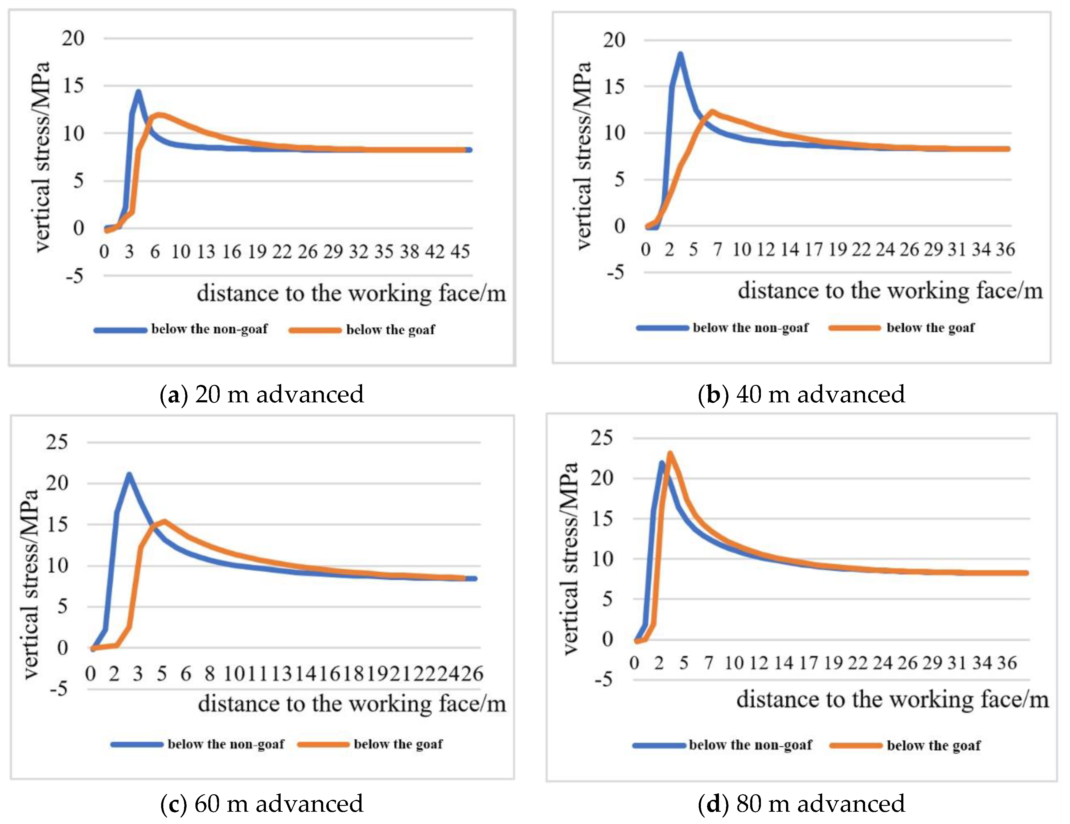
Figure 7.
Distribution of plastic zones with different degrees of stoping below the non-goaf.

Figure 8.
Nephogram of the plastic zones below the goaf.
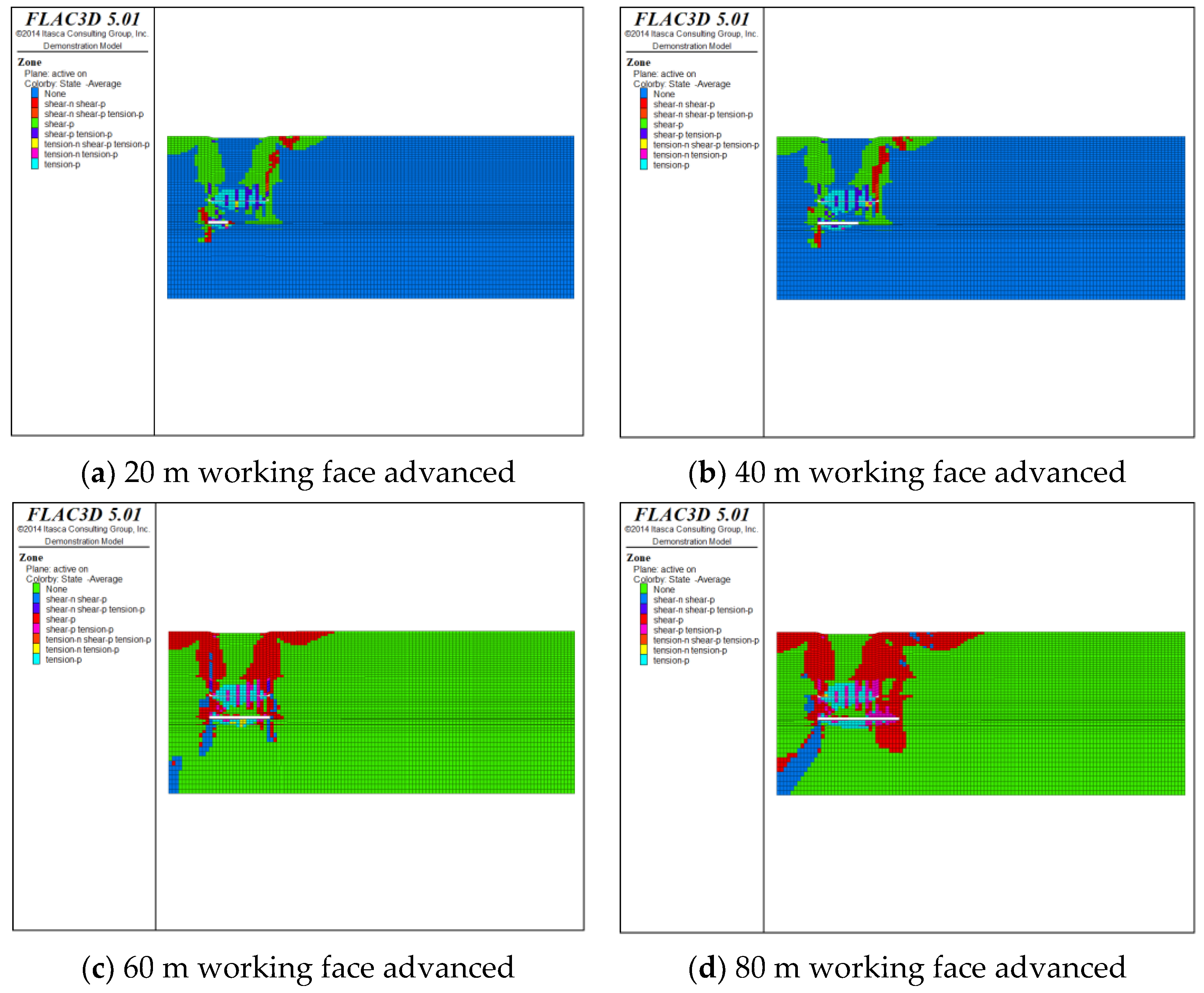
Figure 9.
Schematic diagram of the monitoring system for support resistance.

Figure 10.
Working resistance of supports for the working face under different mining degrees.


Figure 11.
Distribution of working resistance of the 051508 working face supports.


Table 1.
Lithology of the roof and the floor of the coal seam.
| Type of the Roof and Floor | Lithology | Height (m) | Description of Lithology | |
|---|---|---|---|---|
| conditions of the roof and floor of the coal seam | basic roof | 14 coal | 2.49 | A medium-thick coal seam, with a stable coal seam structure and small variation of thickness of the coal seam and with a dirt band. |
| siltstone | 2.92 | Gray, with a large number of root fossils and a hardness coefficient of 3.4. | ||
| fine sandstone | 1.05 | Light gray, composed of quartz mica feldspar, with a hardness coefficient of 3.6. | ||
| siltstone | 1.35 | Gray, with a large number of root fossils and a hardness coefficient of 3.4. | ||
| fine sandstone | 9.25 | Light gray coefficient, composed of quartz mica feldspar, with a hardness coefficient of 3.6. | ||
| siltstone | 3.85 | Gray, with a large number of root fossils and a hardness coefficient of 3.4. | ||
| immediate roof | mud stone | 0.3 | Gray, argillaceous cemented with siltstone bands. | |
| immediate floor | coal streak | 0.2 | Bright black, shiny briquette, lumpy, with a hardness coefficient of 2. | |
| siltstone | 4.48 | Gray, with a large number of root fossils and a hardness coefficient of 3.4. | ||
| mud stone | 0.68 | Gray, argillaceous cemented with siltstone bands. | ||
| basic floor | fine sandstone | 7.82 | Light gray, composed of quartz mica feldspar, with a hardness coefficient of 3.6. |
Table 2.
Attribute parameters of the main rock strata in the 051508 working face [22].
Table 2.
Attribute parameters of the main rock strata in the 051508 working face [22].
| Lithology | Density (Kg/m3) | Shear Modulus (GPa) | Volume Modulus (GPa) | Bulk Modulus (MPa) | Cohesion (MPa) | Internal Frictional Angle (°) |
|---|---|---|---|---|---|---|
| mud stone | 2540 | 2.17 | 3.16 | 1.1 | 2.1 | 26 |
| siltstone | 2470 | 2.71 | 3.93 | 1.9 | 3. 1 | 35 |
| 15 coal | 1290 | 1.39 | 2.33 | 0.74 | 1.6 | 25 |
| 14 coal | 1320 | 1.50 | 2.57 | 0.9 | 1.4 | 24 |
| fine sandstone | 2490 | 2.52 | 3.45 | 1.8 | 2.9 | 34 |
Table 3.
Criteria for weighting of hydraulic supports.
| Measurement Area | Average Resistance (KN) | Mean Square Error (KN) | Judgment Criteria for Weighting (KN) |
|---|---|---|---|
| upper | 3378 | 368 | 3746 |
| middle | 3683 | 471 | 4154 |
| lower | 3591 | 261 | 3852 |
Table 4.
Weighting of the 051508 working face roof.
| Working Face Area | Upper | Middle | Lower | Average | |
|---|---|---|---|---|---|
| first caving step of the immediate roof (m) | 9.4 | 10.6 | 9.0 | 9.7 | |
| first weighting interval of the basic roof (m) | 25.6 | 27.1 | 26.4 | 26.4 | |
| periodic weighting interval (m) | weighting 1 | 14.6 | 16.1 | 17.1 | 16.0 |
| weighting 2 | 13.5 | 15.0 | 15.3 | 14.6 | |
| weighting 3 | 16.6 | 13.5 | 15.0 | 15.1 | |
| weighting 4 | 13.5 | 11.5 | 16.0 | 13.7 | |
| average value of weighting (m) | 14.6 | 14.0 | 15.9 | 14.9 | |
© 2020 by the authors. Licensee MDPI, Basel, Switzerland. This article is an open access article distributed under the terms and conditions of the Creative Commons Attribution (CC BY) license (http://creativecommons.org/licenses/by/4.0/).
Share and Cite
MDPI and ACS Style
Pan, W.; Zhang, S.; Liu, Y. Safe and Efficient Coal Mining Below the Goaf: A Case Study. Energies 2020, 13, 864. https://doi.org/10.3390/en13040864
AMA Style
Pan W, Zhang S, Liu Y. Safe and Efficient Coal Mining Below the Goaf: A Case Study. Energies. 2020; 13(4):864. https://doi.org/10.3390/en13040864
Chicago/Turabian StylePan, Weidong, Shaopeng Zhang, and Yi Liu. 2020. "Safe and Efficient Coal Mining Below the Goaf: A Case Study" Energies 13, no. 4: 864. https://doi.org/10.3390/en13040864
Note that from the first issue of 2016, this journal uses article numbers instead of page numbers. See further details here.