Operational Risk Assessment of Electric-Gas Integrated Energy Systems Considering N-1 Accidents


1
College of Electrical and Information Engineering, Hunan University, Changsha 410082, China
2
Energy Systems Institute, Russian Academy of Sciences, 664033 Irkutsk, Russia
*
Authors to whom correspondence should be addressed.
Energies 2020, 13(5), 1208; https://doi.org/10.3390/en13051208
Submission received: 31 January 2020
/
Revised: 23 February 2020
/
Accepted: 28 February 2020
/
Published: 5 March 2020
(This article belongs to the Special Issue Machine Learning for Energy Systems)
Abstract
:The reliability analysis method and risk assessment model for the traditional single network no longer meet the requirements of the risk analysis of coupled systems. This paper establishes a risk assessment system of electric-gas integrated energy system (EGIES) considering the risk security of components. According to the mathematical model of each component, the EGIES steady state analysis model considering the operation constraints is established to analyze the operation status of each component. Then the EGIES component accident set is established to simulate the accident consequences caused by the failure of each component to EGIES. Furthermore, EGIES risk assessment system is constructed to identify the vulnerability of EGIES components. Finally, the risk assessment of IEEE14-NG15 system is carried out. The simulation results verify the effectiveness of the proposed method.

1. Introduction
Power system and natural gas system are strongly coupled systems. In recent years, the application scenarios of energy field research have gradually changed from single energy systems to multi-energy systems [1,2]. The energy sources are mutually coupled, which can allow the stepwise utilization and collaborative optimization of energy sources. And the mutual support between different energy systems also improves the security and stability of each system. However, it makes the operation and control of multi-energy systems more complicated [3,4]. In terms of system failure, it may be caused by the system’s own factors, or it may be caused by other subsystems propagating the failure through coupling elements, which makes the security of multi-energy systems also more complicated [5,6]. For example, the output power fluctuation of renewable energy may cause the output fluctuation of gas turbine, which leads to the fluctuation of pipeline flow and node pressure of natural gas system. Interruption of gas source or sudden drop of air pressure in natural gas system may cause shutdown of gas turbine in power system, which will force other generators to increase output and cause transmission plugs, further affecting the safe and stable operation of power system. In order to ensure secure and stable operation of EGIES, it is very important for operators to quickly and accurately evaluate the operational risk of the system.
At present, research on integrated energy systems has focused on energy flow analysis [7,8], optimized operation [9,10,11], and collaborative planning [12]. Most of the researches on system risk assessment have stayed in a single energy system, and there are few studies on risk assessment of multi-energy systems. The research on integrated energy system risk assessment is in its infancy, and the research results of this research direction are currently mainly focused on the reliability assessment of integrated energy systems. In [13], the influence of electricity-gas coupling on the operation status of the integrated energy system was studied, but the impact of gas supply risks on the security of the entire system has not been fully considered. In [14], the impact of the shortage for natural gas supply on the operation of the integrated energy system was analyzed, and the impact of intermittent new energy power injection on the feasible region of the natural gas system was also evaluated. Reference [15] proposed universal indicators from the energy link, device link, distribution network link and user link. The security assessment of the regional integrated energy system was performed. However, the risk of accidents caused by component failures to the system was not considered in [14,15]. In [16], the sufficiency and safety of the integrated energy system were analyzed, and the key fault scenarios and extreme operation scenarios were identified using the natural gas transient power flow model and the power system interlocking fault model. In [17], reliability indexes such as expected electric/gas/heat demand not supplied, expected wind power abandoned and power-to-gas device capacity utilization were proposed. [16,17] were not refined to evaluate the operating status of the integrated system. The above research results evaluate the reliability level of integrated energy system from the perspective of long-term planning, which is of great significance for system optimization planning and operation control. However, the quantitative calculation results based on the short-term scale of system operation risk are more helpful for the operating personnel to make online decisions. Operation regulators need to conduct risk assessment based on the real-time operation state of the system, so as to find potential safety hazards, give timely warnings, and assist in making decisions to adjust the current operation mode to ensure the safety of the system.
In this article, an EGIES steady-state analysis model considering operating constraints is established. Establishing natural gas system evaluation indicators including node low pressure severity, pipeline overload severity, pipeline tidal distribution severity, and gas load loss, we combine the power system risk assessment indicators to establish the EGIES assessment system. We also identify vulnerable components in EGIES by considering the possibility/severity of component failure. Finally, the risk assessment of IEEE14-NG15 EGIES was conducted to verify the effectiveness of the proposed model and method.
2. The Steady-State Modeling and Power Flow Calculation of EGIES
Due to the differences in physical characteristics of different electric-gas integrated energy system energy systems, our modeling needs to be coordinated uniformly. For the coupling of EGIES, it is actually a key element in the transformation of energy forms. In the modeling process, the energy transformation characteristics should be considered, similar to the energy hub.
2.1. Gas Turbine Condition Analysis Model
A gas turbine is an energy converter between the natural gas pipeline network and the power grid. For a natural gas pipeline network, a gas turbine can be equivalent to a natural gas load; for a power system, it can be equivalent to an adjustable output power source. The relationship between the gas consumption of a gas turbine and its active output can be expressed as follows [18]:
where is the amount of gas consumed by the i-th gas turbine; , , are the electrical energy conversion coefficients of the gas turbine; is the active output of the i-th gas turbine.
2.2. Energy Flow Model of Gas Pressure Regulator
The compressor is an important non-pipeline component in the natural gas pipeline network, and its parameters mainly include flow rate and inlet and outlet pressure. The relationship between the power required by the compressor and its air pressure ratio can be calculated by the following formula:
where HP(W) is power; () is the equivalent flow through the compressor under standard conditions; is the variable index (here is 1.27); is the compressor efficiency, generally maintained at 0.75–0.85; , , are fuel ratio coefficients; is the amount of gas consumed by the gas-consuming compressor; is the output air pressure; is the input air pressure.
2.3. Natural Gas Pipeline Model
In the case of fixed external conditions, the flow of the pipeline is mainly related to the pressure at the head and end of the pipeline. Given the two variables of the pipeline flow, the pressure at the beginning of the pipeline, and the pressure at the end, the unknown variable can be solved. According to the conservation law of natural gas hydrodynamic mass and Bernoulli’s equation, the natural gas flow equations of different pressure levels based on certain assumptions are as follows [19,20]:
These three types are applicable to natural gas pipelines with pipeline pressures below 0–0.75 bar, 0.75–7.0 bar and greater than 7.0 bar, respectively. i and j represent the beginning and end of the natural gas pipeline respectively, and represents the flow from node i to node j through the pipeline; and are the pressure at the beginning and end of the pipe; is the diameter of the pipe; F is the non-directional friction coefficient; is the average temperature of natural gas, is the temperature under standard conditions; is the specific gravity of natural gas; is the average compressibility coefficient.
2.4. The Steady-State Power Flow Model of EGIES
For the EGIES system, each subsystem has its own physical characteristics, so the original physical characteristics are still maintained during the modeling process. The coupling link mainly plays the interaction between the systems, so the transformation characteristics and physical characteristics of the coupling link are mainly considered. The expression of the EGIES steady-state model cited in the article [3] is:
These three formulas respectively represent the equations of the coupling of the power grid, natural gas network and energy; represent power system variables including power, phase angle, and voltage amplitude; represent natural gas system variables including pressure and flow; represent the energy coupling variable including the power conversion factor.
2.5. Flow Calculation for EGIES
The similarity of power system and natural gas system in the solution of power flow is mainly reflected in two aspects:
- (1)
- According to the law of conservation of mass, Kirchhoff’s first law and Kirchhoff’s second law are also applicable in natural gas systems. Correspondingly, natural gas flow solutions can be formed focusing on nodes and closed loops [20].
- (2)
- The key to solving power flow of power system and natural gas system is to use high-efficiency iterative algorithm to solve high-dimensional nonlinear equations. Therefore, the solution method represented by Newton’s method can be extended to natural gas systems [21].
In this paper, the nodal method is used to solve the power flow equation of the natural gas system. For the n-node natural gas system, according to Equation (5), when the k-th iteration is solved using Newton’s method, the correction equation is as follows:
Among them:
where is the error vector of the function sought; is the current Jacobian matrix; is the current correction vector. By iterating the above formula repeatedly until the convergence condition is satisfied, the result can be finally obtained.
The main power link of the comprehensive energy system is distribution network, and its main features include radial operation, large branch R/X ratio, multi-phase unbalance, multiple branches, and the existence of renewable energy access. In addition, with the gradual close coupling of multiple energy sources in the integrated energy system, the power system is not only the output object of other energy links, but also the energy supplier of the coupling links in other energy systems. These characteristics put forward new requirements for the steady-state analysis of power links in the integrated energy system, and the influence of other energy links coupled with it should be considered in the solution process. The flow calculation process of EGIES is shown in Figure 1.
In power flow calculation of power system, its basis is node voltage current equation , which is expressed by power variable and becomes:
where and are respectively the injection current of node m and the voltage of node n. is an element in the admittance matrix. and are respectively the injected active power and reactive power of node m. is the conjugate of the voltage vector; N is the number of system nodes. Because distribution network power flow solving technology is very mature, this article will not repeat them.
3. Accident Severity Assessment Indexes of EGIES
The accident severity assessment of EGIES include power system and natural gas system accident severity assessment. The power system evaluation indicators have been described in [22], so this article will not repeat them. Natural gas system evaluation indicators include node low pressure severity, pipeline overload severity, pipeline flow distribution severity, and gas network load loss severity. The above indicators can reflect the operating characteristics of the natural gas system from some aspects.
3.1. Low-Pressure Severity Index for Natural Gas System Nodes
Node pressure reflects the gas supply capacity of the natural gas system. Considering the existence of factors such as non-directional friction coefficient, there is a transmission security zone due to the maximum transmission distance of natural gas during the transmission process. In the area, the pressure at the end of the pipe can be controlled within safe limits. The severity of low gas pressure at the nodes of the natural gas network indicates the gas supply capacity of the nodes. The low-pressure severity function of node i of the natural gas pipeline network is defined as:
where is the pressure of the natural gas network node i; is the rated gas pressure of the natural gas network node i; is the maximum low-pressure risk threshold.
The severity of low-pressure in a natural gas system can be expressed as:
where N is the total number of nodes in the natural gas pipeline network; is a function of the low-pressure severity of natural gas network node i.
3.2. Gas Pipeline Overload Severity Index
When the transmission capacity of the power line exceeds its limit value, the thermal effect phenomenon will accelerate the aging of the line and even cause the line to fail. Analogous to the overload severity of power lines, the overload severity of natural gas pipelines is proposed to measure the pipeline operating status. The pipeline overload severity function between node i and node j can be expressed as:
where is the pipeline flow between nodes i and j; is the maximum transmission flow, which represents the threshold of the overload risk of the branch; is the set pipeline overload risk threshold, which is generally 90% of .
Therefore, the pipeline overload severity of the natural gas network can be expressed as:
where M is the total number of natural gas pipelines; is the pipeline overload severity function of natural gas pipeline network node i and node j.
3.3. Gas Flow Distribution Severity Index of Natural Gas System
This article uses tidal current entropy [23] to quantitatively describe the equilibrium of the pipeline flow distribution. The entropy theory was first applied to the laws of thermodynamics, and then gradually applied to systems such as information science and statistical physics. The entropy is a measure, which reflects the chaotic and disordered state of the system. If the order degree of the system is lower, the entropy is higher, Conversely, the higher the order degree of the system, the smaller its entropy. Although the average load rate of the electric power system and the natural gas system can reflect the load level of the system as a whole, the description of the load rate distribution of the line is insufficient and imperfect. When the system is at a certain load level, the following can happen: it may be that the load rate of all the lines is near the average load rate, or it may be that the load rate of some lines is much higher than the average load rate while the load rate of some lines is much lower than the average load rate. This information cannot be represented by the average load rate, and it is not possible to use the average load rate as an indicator to study how the unbalanced distribution of power flows will affect system security. Therefore, entropy theory is introduced in this paper to reflect the distribution of power flow in the system. The amount of gas transmitted by the natural gas system is closely related to the capacity of the natural gas pipeline. Gas lines with large natural gas pipelines carry large volumes of gas, and conversely, small volumes of natural gas pipelines carry small volumes of gas. In this way, the flow distribution of the natural gas system is balanced. The flow entropy of the natural gas pipeline is defined here as:
where C is taken as ln10; the interval is equally divided into 20 parts, and is the ratio of the lines with the load ratio belonging to the same interval to the total number of lines.
When the load rates of all the pipelines are not in the same load rate interval, the power flow entropy reaches the maximum:
At this time, the distribution of the pipeline flow is extremely uneven. Once the load or other factors cause fluctuations in the operating state, the line with a high load rate is likely to fluctuate and exceed the safe range, which will cause a failure. The larger the value of the flow entropy, the more uneven the flow distribution, the lower the security and the lower the line utilization.
The flow distribution severity function of a natural gas system can be expressed as:
where is the pipe flow entropy of the system after component failure; is the steady-state entropy of the pipeline before the component fails; is the maximum flow value of the natural gas system.
3.4. Gas Load Loss Severity Index
Regardless of whether it is a power network or a natural gas pipeline network, it is important to transfer energy from the supply side to the user side. Therefore, the gas load loss severity is an important indicator for evaluating the system. n this paper, the electric-gas load reduction optimization model [17] considering component faults is adopted to achieve as much reserved load as possible in case of system failure. The gas load loss ratio of natural gas pipeline network is defined as:
where is the proportion of natural gas pipeline load loss after the accident; is the gas load of natural gas node i before the fault; is the gas load of node i before and after the fault.
The gas load loss severity function is defined as:
where is the threshold for the loss of the natural gas system, and 20% of the total natural gas load is taken in this paper.
4. EGIES Risk Assessment Considering N-1 Failure
In this chapter, combined with the severity assessment index of the EGIES established in the second part, the risk assessment model of EGIES established based on the risk assessment theory [24,25] and the failure probability of EGIES is considered. Finally, risk values of components in the electrical integrated energy system are calculated to identify vulnerable links.
4.1. EGIES Failure Probability Considering N-1 Failure
It can be seen from the statistical data that the occurrence probability of power system accidents basically conforms to the characteristics of the Poisson distribution [26]. The probability of power system accidents can be expressed as:
where is the i-th accident in the power system; is the probability of accident ; is the failure rate of component i.
In a natural gas system, the probability of component accidents also meets the Poisson distribution law [27], and can be similarly expressed as:
where is the i-th accident in the natural gas pipeline network; is the probability of the accident; is the failure rate of the natural gas pipeline network component i.
The failure rates of the power system and the natural gas system are independent of each other, when the failures of the components in the two systems are considered separately. The following two formulas show the component failure rates of the natural gas system and the power system in the EGIES considering N-1 failure:
where and are respectively the initial failure rates of the electrical and natural gas network components; and are respectively the failure probability of the electrical and gas network components; and are respectively the total components of the electrical and gas network.
4.2. Risk Assessment Model of EGIES
In this paper, the coupling effect between EGIES multi-energy systems is considered, and the comprehensive risk assessment indicators as shown below are established based on the risk assessment theory:
among them:
where , , and are respectively low voltage severity, line overload severity, power flow distribution severity and power loss load severity; where , , and are respectively low-pressure severity, gas pipeline overload severity, Gas flow distribution severity and Gas load loss severity.
4.3. EGIES Security Assessment Process Based on Risk Theory
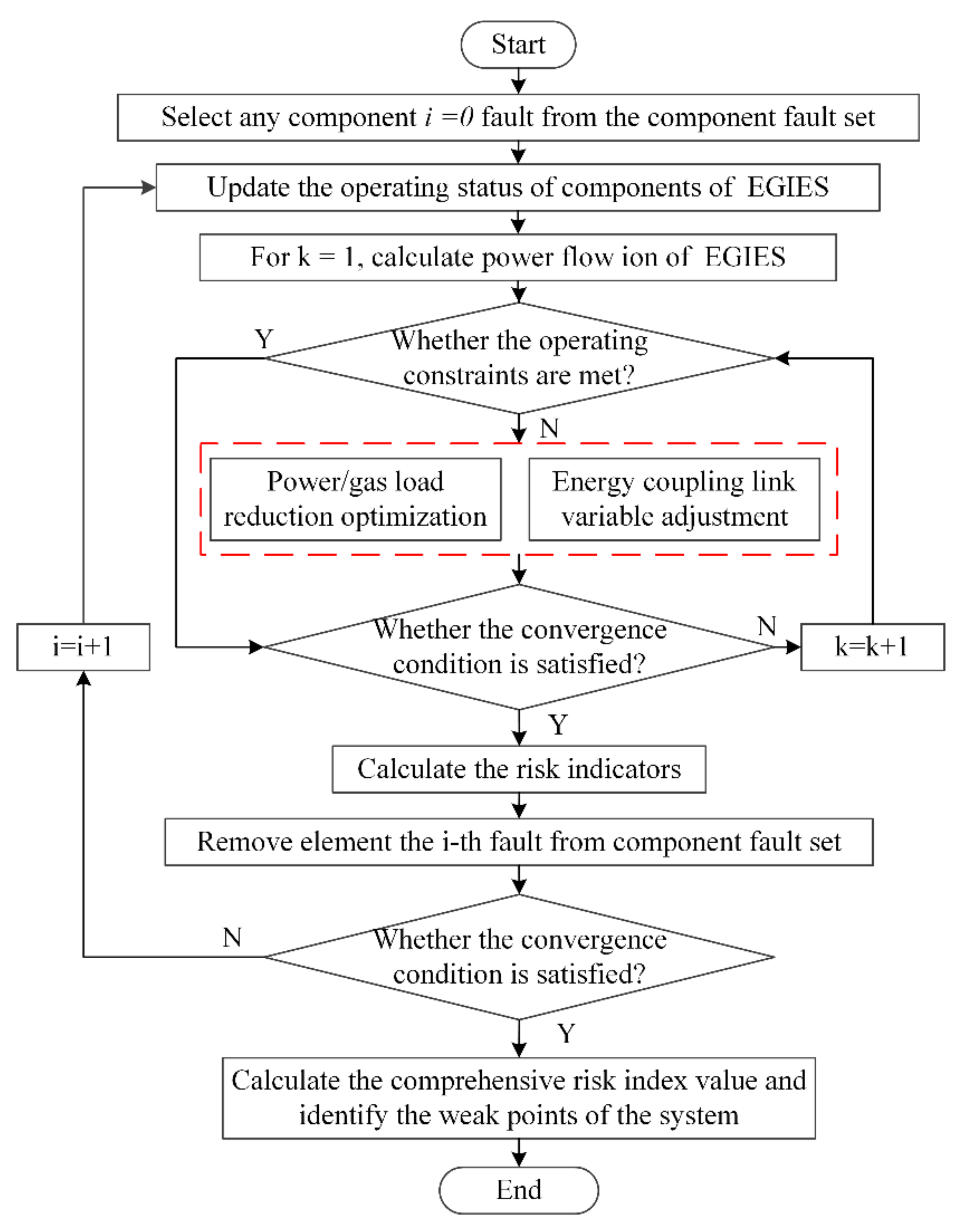
The main steps of EGIES security assessment method based on risk theory [25] are as follows, and the process is shown in Figure 2:
- (1)
- Select the target component and formulate the corresponding component accident set for the target component; Through the simulation of component failure scenarios, the ability of EGIES to maintain normal operation was analyzed.
- (2)
- Update the running state of each component according to the proposed component accident set; EGIES steady-state model was established to analyze the operation status of typical accident scenarios. In the convergence calculation of the model, not only the convergence of the power flow of the EGIES coupling system is guaranteed, but also the operation of the system is guaranteed to meet the constraint conditions. If not, the cycle iteration is conducted by adjusting the energy coupling variable or optimizing load reduction to finally meet the operating conditions.
- (3)
- Calculate the EGIES risk. Through the established EGIES evaluation system, the vulnerability and importance of each component of the system were identified horizontally, and the main impact of the component on the system operation was evaluated vertically.
5. Case Study
The EGIES system shown in Figure 3 is simulated and analyzed based on GAMS and MATLAB software. The system includes IEEE-14 nodes of power system and 15 nodes of natural gas network. The coupling elements include three gas turbines and three compressors. The operation constraints in the EGIES include are shown as follows:
- (1)
- The voltage limit range of power system nodes is between 0.95 and 1.05. The transmission power of the line is within the limit range.
- (2)
- The lower limit of the gas pressure at the natural gas pipeline network system is 45 bar; the amount of natural gas flowing through the pipeline cannot exceed its limit value; the injected gas volume of the gas sources does not exceed 25,700; the compression ratio of the compressor does not exceed 1.6, the gas volume does not exceed 7200, 1500, 8000 at the compressors Q5, Q12 and Q16.
It was assumed that the reliability of the natural gas pipeline, the compressor and the power line is 0.90, 0.90 and 0.92 respectively. The Pipeline parameters of 15-node natural gas system are shown in Table A1 of Appendix A, and the gas loads of natural gas system are shown in Table A2 of Appendix A. In the initial state of EGIES, the risk indicators of severity of natural gas system accident and severity of power system accident are shown in Figure 4 and Figure 5 respectively.
Taking the outlet pipeline fault of natural gas source N1 (Element label 1 represents the risk value of the system under normal operation, component Q1 is labeled 2, component Q2 is labeled 3, and so on in Figure 4, Figure 5, Figure 6 and Figure 7) as an example, it is illustrated that the above evaluation indicators can correctly reflect the changes in operating state of other parts of EGIES caused by gas network fault. As can be seen from Figure 4, a large number of air sources are missing, resulting in a large resection of the gas load. At the same time, the amount of gas transmitted in the pipeline also decreases correspondingly, resulting in low node pressure, low pipeline overload and abnormal power flow distribution. The 90 MW gas turbine at node E3 supports the operation of the whole large power grid. Due to the severe reduction of gas supply, the gas turbine output is seriously reduced, resulting in a substantial reduction of power load.
Although the E3 gas turbine is inadequately powered, other generators can still maintain the power supply of part of the electrical load. Therefore, there is a large loss of electrical load and an uneven distribution of power flow, but there is no serious line overload. As a result of the above process, the gas flow through the compressor Q5 and the compressor Q12 is zero, and the energy supply of the compressor Q16 is zero, which can also be reflected in Figure. 6 of the operating state of the three compressors.
Taking the fault of 60 MW gas turbine outlet line connected with node E8 (component Q32 is labeled 33 in in Figure 4, Figure 5, Figure 6 and Figure 7) as an example, it is illustrated that the above evaluation indicators can correctly reflect the changes in operating state of other parts of EGIES caused by power grid failure. It can be seen from Figure 5 that the state change process of the EGIES after a gas turbine failure is similar to the N1 outlet pipeline failure scenario described above. The power generated by the gas turbine cannot be supplied to the system due to failure of the power line at the outlet of the gas turbine. Therefore, the natural gas supply to the gas turbine by the node N12 must be interrupted, and the operating status of the gas network also changes accordingly. Unlike the first case, the power line is severely overloaded in the second case. The main reason is that different energy systems have different definitions of load overload. In power systems, a load loss of more than 20% is defined as a severe load loss. In fact, in the first case, only 45.54% of the electric load was retained, while in the second case, 74.35% was retained. The greater the electric load retention, the higher the possibility of overload on power lines.
According to Equation (22), the comprehensive risk index value of EGIES can be calculated. The top ten comprehensive risk index of components is shown in Table 1, which include the outlet line of generation. the compressor and the outlet pipeline of the gas source and so on. The distribution of comprehensive risk index of components is shown in Figure 7. According to the integrated risk index curve of EGIES components, the vulnerable links of the EGIES can be identified.
As can be seen from Table 1 and Figure 7, the comprehensive risk value of component Q32 is the highest. The reason is that Q32 is the outlet line of the generator. If a fault occurs, Q32 cannot supply power to the system, and the system will suffer serious power load loss. Considering that the generator connected to Q32 is a gas turbine, it is also sensitive to the fault disturbance of the natural gas network. Q1, Q17, Q32 and Q5 rank higher in the table. Q1 and Q17 are both gas source outlet pipelines, which undertake the task of supplying gas to the natural gas system. If Q1 and Q17 fail, the gas source will not be able to supply gas normally, and the system will suffer serious loss of gas load. In addition, the terminal nodes of Q1 and Q17 are connected to the gas turbine, which are sensitive to the fault disturbance of the power grid. Q5 is the line where the air pressure regulating device is located, which is responsible for the air pressure regulation of the natural gas network. If Q5 fails, the pressure adjustment of the natural gas system will be abnormal, and natural gas cannot be normally transmitted. Moreover, Q5 is the first end of multiple gas supply lines, which is also the reason for the higher risk value. The reasons for the higher risk values of element Q33 are discussed below.
According to the method discussed in this article, combined with each severity index after the failure of comprehensive energy system, the comprehensive risk value is used to evaluate the security risk of N-1 failure. Through comparative analysis with the methods proposed in reference [28], the ranking results of the top 10 comprehensive values of risk obtained by the two methods are shown in Table 1. It can be seen from Table 2 that the ranking of the first 10 high-risk faults obtained in this paper is very similar to the results of the method in literature [28], which proves the correctness and availability of the method in this paper.
The difference between the risk ranking obtained in this paper and the method proposed in [28] mainly lies in Q17, Q33 and Q29. The reasons for the higher risk of Q17 have been mentioned above and will not be repeated. Although the component Q33 is traversed by the shortest path between fewer power-load pairs, the reason for the greater risk of Q33 is that its end is connected to the air pressure regulator, which is greatly affected by the disturbance of the natural gas network. Q29 is not directly connected to the gas unit and is less affected by the fault of the gas network. However, Q29 is passed by more power-load node pairs, and it is in the key position of network energy transmission, which plays an important role in shortening the electrical distance between power generation node and load node. Once Q29 fails, other lines will be overloaded, which will easily cause a grid cascading fault.
6. Summary
In this paper, a comprehensive energy risk assessment index and a risk assessment strategy for the EGIES considering component n-1 accident are proposed. Firstly, the steady state power flow model of the EGIES is established to analyze the safe operation of each subsystem. Secondly, the vulnerability of components is analyzed according to the severity function of IENGS, and the critical and non-critical components in the system are identified. Thirdly, IENGS risk assessment model is established to analyze the security of EGIES running state. Furthermore, an IENGS risk assessment method considering n-1 accidents is proposed to analyze the vulnerable links in the electric-gas integrated energy system. The research shows that the EGIES risk assessment method proposed in this paper can assess the coupling and interaction effects between subsystems, reflect the security of system operation to a certain extent, and provide scientific decision basis for relevant personnel.
Author Contributions
Conceptualization, Y.L. and Y.C.; methodology, D.S. and Y.C.; writing—original draft preparation, H.L. and Z.Z.; writing—review and editing, H.L., Z.Z. and Y.L.; investigation, Y.L. and Y.C.; supervision, Y.C. and D.S.; funding acquisition, Y.L., Y.C. and D.S. All authors have read and agreed to the published version of the manuscript.
Funding
This work was supported in part by the International Science and Technology Cooperation Program of China under Grant 2018YFE0125300, in prat by the Innovative Construction Program of Hunan Province of China under Grant 2019RS1016, in part by the 111 Project of China under Grant B17016, and in part by the Excellent Innovation Youth Program of Changsha of China under Grant KQ1802029. This work is fulfilled as part of the program of fundamental research of SB of Russian Academy of Sciences, reg. no. AAAA-A17-117030310442-8, research project III.17.3.1.
Conflicts of Interest
The authors declare no conflict of interest. The funders had no role in the design of the study; in the collection, analyses, or interpretation of data; in the writing of the manuscript, or in the decision to publish the results.
Appendix A

Table A1.
Pipeline parameters of 15-node natural gas system.
| Start of Pipeline i | End of Pipeline j | Length L(m) | Diameter D(mm) |
|---|---|---|---|
| 1 | 2 | 750 | 5000 |
| 2 | 3 | 400 | 5000 |
| 2 | 4 | 275 | 5000 |
| 2 | 5 | 275 | 5000 |
| 3 | 6 | 250 | 6000 |
| 3 | 7 | 275 | 6000 |
| 3 | 8 | 275 | 5000 |
| 4 | 7 | 175 | 5000 |
| 5 | 6 | 175 | 6000 |
| 6 | 8 | 200 | 500 |
| 6 | 12 | 400 | 5000 |
| 7 | 8 | 175 | 500 |
| 7 | 9 | 250 | 500 |
| 9 | 10 | 200 | 500 |
| 10 | 11 | 150 | 500 |
| 12 | 13 | 350 | 2000 |
| 12 | 14 | 750 | 5000 |
| 12 | 15 | 350 | 2000 |
Table A2.
Natural gas loads of 15-node natural gas system.
| Node Number | Gas Load (m3/h) |
|---|---|
| 2 | 14,595 |
| 3 | 2000 |
| 4 | 1750 |
| 5 | 1570 |
| 6 | 8500 |
| 7 | 1500 |
| 8 | 1860 |
| 9 | 650 |
| 10 | 450 |
| 11 | 290 |
| 12 | 100,00 |
| 13 | 4000 |
| 15 | 4000 |
References
- Huang, A.Q.; Crow, M.L.; Heydt, G.T.; Zheng, J.P.; Dale, S.J. The future renewable electric energy delivery and management (FREEDM) system: The energy internet. Proc. IEEE 2011, 99, 133–148. [Google Scholar] [CrossRef]
- Geidl, M.; Koeppel, G.; Favre-Perrod, P.; Klockl, B.; Andersson, G.; Frohlich, K. Energy hubs for future. IEEE Power Energy Mag. 2007, 5, 24–30. [Google Scholar] [CrossRef]
- Wang, W.; Wang, D.; Jia, H.; Chen, Z.; Guo, B.; Zhou, H.; Fan, M. Steady state analysis of electricity-gas regional integrated energy system with consideration of NGS network status. Proc. CSEE 2017, 37, 1293–1304. [Google Scholar]
- Chen, S.; Wei, Z.; Sun, G.; Wang, D.; Zhang, Y.; Ma, Z. Stochastic look-ahead dispatch for coupled electricity and natural-gas networks. Electr. Power Syst. Res. 2018, 164, 159–166. [Google Scholar] [CrossRef]
- Shahidehpour, M.; Fu, Y.; Wiedman, T. Impact of natural gas infrastructure on electric power systems. Proc. IEEE 2005, 93, 1042–1056. [Google Scholar] [CrossRef]
- Qiao, X.; Zou, Y.; Li, Y.; Chen, Y.; Liu, F.; Jiang, L.; Cao, Y. Impact of uncertainty and correlation on operation of micro-integrated energy system. Int. J. Electr. Power Energy Syst. 2019, 112, 262–271. [Google Scholar] [CrossRef]
- Martinez-Mares, A.; Fuerte-Esquivel, C.R. A unified gas and power flow analysis in natural gas and electricity coupled networks. IEEE Trans. Power Syst. 2012, 27, 53–63. [Google Scholar] [CrossRef]
- Unsihuay-Vila, C.; Marangon-Lima, J.W.; de Souza, A.C.Z.; Perez-Arriaga, I.J.; Balestrassi, P.P. A model to long-term, multiarea, multistage and integrated expansion planning of electricity and natural gas systems. IEEE Trans. Power Syst. 2010, 25, 1154–1168. [Google Scholar] [CrossRef]
- Wu, X.; Li, Y.; Tan, Y.; Cao, Y.; Rehtanz, C. Optimal energy management for the residential MES. IET Gener. Transm. Distrib. 2019, 13, 1786–1793. [Google Scholar] [CrossRef]
- Badal, F.R.; Das, P.; Sarker, S.K.; Das, S.K. A survey on control issues in renewable energy integration and microgrid. Prot. Control Mod. Power Syst. 2019, 4, 87–113. [Google Scholar] [CrossRef] [Green Version]
- Annamraju, A.; Nandiraju, N. Robust frequency control in a renewable penetrated power system: An adaptive fractional order-fuzzy approach. Prot. Control Mod. Power Syst. 2019, 4, 181–195. [Google Scholar] [CrossRef] [Green Version]
- Wu, L.; Meng, K.; Xu, S.; Li, S.; Ding, M.; Suo, Y. Planning and optimal energy management of combined cooling, hearting and power microgrid: A review. Int. J. Energy Syst. 2014, 54, 26–37. [Google Scholar]
- Chertkov, M.; Backhaus, S.; Lebedev, V. Cascading of fluctuations in interdependent energy infrastructures: Gas-grid coupling. Appl. Energy 2015, 160, 541–551. [Google Scholar] [CrossRef] [Green Version]
- Zlotnik, A.; Chertkov, M.; Turitsyn, K. Assessing risk of gas shortage in coupled gas-electricity infrastructures. In Proceedings of the 2016 49th Hawaii International Conference on System Sciences (HICSS), Koloa, HI, USA, 5–8 January 2016. [Google Scholar]
- Chen, B.; Liao, Q.; Liu, T.; Wang, W.; Wang, Z.; Chen, S. Comprehensive evaluation indices and methods for regional integrated energy system. Autom. Electr. Power Syst. 2018, 42, 174–182. [Google Scholar]
- Antenucc, N.; Sansavini, D. Adequacy and security analysis of interdependent electric and gas networks. Proc. Inst. Mech. Eng. Part O J. Risk Reliab. 2018, 232, 121–129. [Google Scholar]
- Yu, J.; Liao, Q.; Ma, M.; Guo, L.; Zhang, S. Reliability evaluation of integrated electrical and natural-gas system with power-to-gas. Proc. CSEE 2018, 38, 708–715. [Google Scholar]
- Zhang, Y. Study on the Methods for Analyzing Combined Gas and Electricity Networks; China Electric Power Research Institute: Beijing, China, 2005. [Google Scholar]
- Osiadacz, A.J. Simulation and Analysis of Gas Network; E. & F.N. Spon Ltd.: London, UK, 1986. [Google Scholar]
- Abeysekera, M.; Wu, J.; Jenkins, N.; Rees, M. Steady state analysis of gas networks with distributed injection of alternative gas. Appl. Energy 2016, 164, 991–1002. [Google Scholar] [CrossRef] [Green Version]
- Munoz, J.; Jimenez-Redondo, N.; Perez-Ruiz, J. Natural gas network modeling for power systems reliability studies. In Proceedings of the 2003 IEEE Power Tech Conference Proceedings, Bologna, Italy, 23–26 June 2003. [Google Scholar]
- Liu, P.; Li, H.; Zhao, Y. Power grid security risk assessment considering comprehensive element importance index. Electr. Power Autom. Equip. 2015, 35, 132–138. [Google Scholar]
- Cao, Y.; Wang, G.; Cao, L.; Ding, L. An identification model for self-organized criticality of power flow entropy. Autom. Electr. Power Syst. 2011, 35, 1–6. [Google Scholar]
- Praks, P.; Kopustinskas, V.; Masera, M. Probabilistic modelling of security of supply in gas networks and evaluation of new infrastructure. Reliab. Eng. Syst. Saf. 2015, 144, 254–264. [Google Scholar] [CrossRef]
- Chen, H.; Jiang, Q.; Cao, Y.; Han, Z. Risk-Based Vulnerability Assessment in Complex Power Systems. Power Syst. Technol. 2005, 29, 12–17. [Google Scholar]
- Hua, W.; McCalley, J.D.; Vittal, V. Risk based voltage security assessment. IEEE Trans. Power Syst. 2000, 15, 1247–1254. [Google Scholar]
- Tee, K.F.; Pesinis, K. Reliability prediction for corroding natural gas pipelines. Tunn. Undergr. Space Technol. 2017, 65, 91–105. [Google Scholar] [CrossRef]
- San, M.; Bao, M.; Ding, Y.; Xue, Y.; Yang, Y. Identification of Vulnerable Lines in Power Grid Considering Impact of Natural Gas Network. Autom. Electr. Power Syst. 2019, 43, 34–43. [Google Scholar]
Figure 1.
Flow chart of EGIES flow calculation.

Figure 2.
Flow chart of EGIES security assessment.

Figure 3.
IEEE14-NG15 system structure diagram.

Figure 4.
Natural gas system accident severity.

Figure 5.
Power system accident severity.

Figure 6.
Compressor operating ratio.

Figure 7.
EGIES components comprehensive risk index value.

Table 1.
EGIES components comprehensive risk index value of the top ten.
| Ranking | Element | Comprehensive Risk Index Value |
|---|---|---|
| 1 | Q32 | 3.874359 |
| 2 | Q1 | 3.547659 |
| 3 | Q17 | 3.005848 |
| 4 | Q33 | 2.898421 |
| 5 | Q5 | 2.687361 |
| 6 | Q35 | 2.308918 |
| 7 | Q16 | 2.143113 |
| 8 | Q29 | 1.904551 |
| 9 | Q24 | 1.583715 |
| 10 | Q8 | 1.285279 |
Table 2.
Comparison of the top 10 risk values of N-1 accidents.
| Ranking | The Method in This Paper | The Method in Reference [28] |
|---|---|---|
| 1 | Q32 | Q32 |
| 2 | Q1 | Q1 |
| 3 | Q17 | Q5 |
| 4 | Q33 | Q16 |
| 5 | Q5 | Q24 |
| 6 | Q35 | Q8 |
| 7 | Q16 | Q12 |
| 8 | Q29 | Q23 |
| 9 | Q24 | Q35 |
| 10 | Q8 | Q33 |
© 2020 by the authors. Licensee MDPI, Basel, Switzerland. This article is an open access article distributed under the terms and conditions of the Creative Commons Attribution (CC BY) license (http://creativecommons.org/licenses/by/4.0/).
Share and Cite
MDPI and ACS Style
Liu, H.; Li, Y.; Cao, Y.; Zeng, Z.; Sidorov, D. Operational Risk Assessment of Electric-Gas Integrated Energy Systems Considering N-1 Accidents. Energies 2020, 13, 1208. https://doi.org/10.3390/en13051208
AMA Style
Liu H, Li Y, Cao Y, Zeng Z, Sidorov D. Operational Risk Assessment of Electric-Gas Integrated Energy Systems Considering N-1 Accidents. Energies. 2020; 13(5):1208. https://doi.org/10.3390/en13051208
Chicago/Turabian StyleLiu, Hua, Yong Li, Yijia Cao, Zilong Zeng, and Denis Sidorov. 2020. "Operational Risk Assessment of Electric-Gas Integrated Energy Systems Considering N-1 Accidents" Energies 13, no. 5: 1208. https://doi.org/10.3390/en13051208
Note that from the first issue of 2016, this journal uses article numbers instead of page numbers. See further details here.