Figure 1.
Schematic view of an axial swirler.
Figure 1.
Schematic view of an axial swirler.
Figure 2.
Geometrical parameters of the main elements of an axial swirler. Where Dsw is the swirler diameter, θ is the vane angle, Dhub is the swirler hub diameter, c is the vane chord, s is the vane space, and z is the annular space length formed by the hub diameter and the swirler diameter.
Figure 2.
Geometrical parameters of the main elements of an axial swirler. Where Dsw is the swirler diameter, θ is the vane angle, Dhub is the swirler hub diameter, c is the vane chord, s is the vane space, and z is the annular space length formed by the hub diameter and the swirler diameter.
Figure 3.
Flow chart of design procedure.
Figure 3.
Flow chart of design procedure.
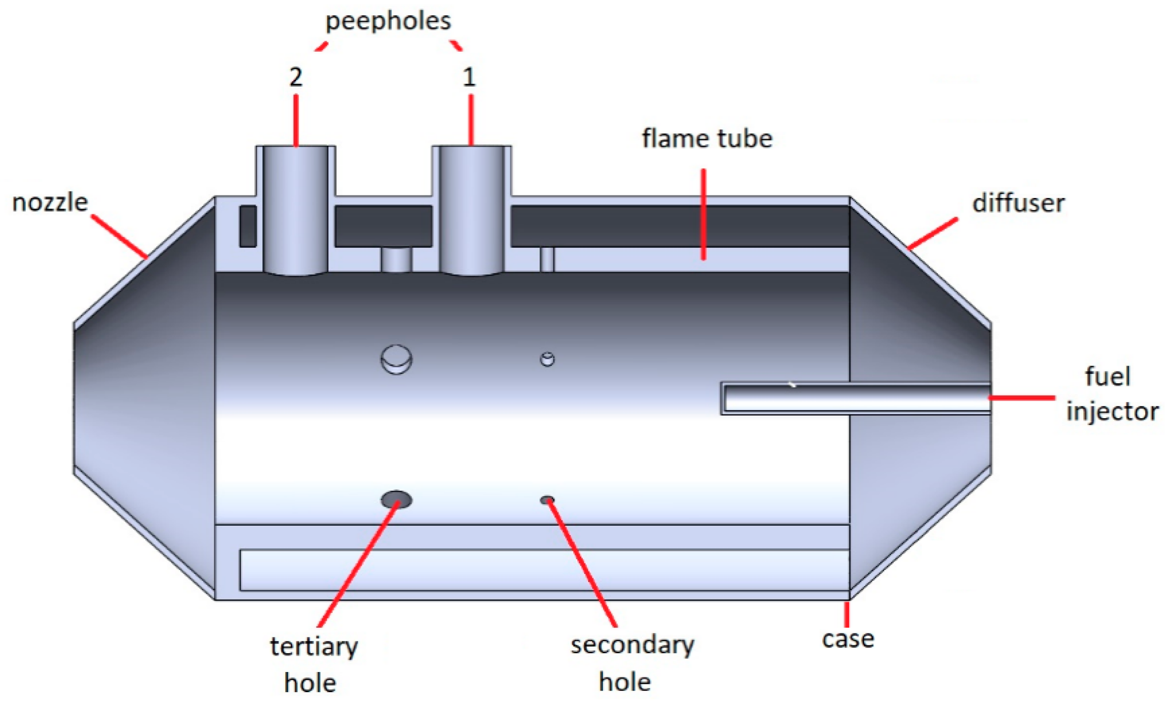
Figure 4.
Diffuse flame combustion chamber.
Figure 4.
Diffuse flame combustion chamber.
Figure 5.
Optimized design of swirler with injector.
Figure 5.
Optimized design of swirler with injector.
Figure 6.
Mesh used in the computational fluid dynamics (CFD) model of the combustion chamber, including a view of the boundary layer on the swirler vanes (right), the boundary of the thermocouple (top), and the elements of the burner (bottom).
Figure 6.
Mesh used in the computational fluid dynamics (CFD) model of the combustion chamber, including a view of the boundary layer on the swirler vanes (right), the boundary of the thermocouple (top), and the elements of the burner (bottom).
Figure 7.
Swirlers compared in numerical analysis. (a) baseline swirler, (b) front view of the baseline swirler, (c) proposed optimized swirler, (d) front view of the proposed optimized swirler.
Figure 7.
Swirlers compared in numerical analysis. (a) baseline swirler, (b) front view of the baseline swirler, (c) proposed optimized swirler, (d) front view of the proposed optimized swirler.
Figure 8.
Path lines of velocity along the yz plane of a CFD model of a combustion chamber. (a) Recirculation zone generated by the optimized swirler model, (b) recirculation zone generated by the baseline swirler model.
Figure 8.
Path lines of velocity along the yz plane of a CFD model of a combustion chamber. (a) Recirculation zone generated by the optimized swirler model, (b) recirculation zone generated by the baseline swirler model.
Figure 9.
View of air velocity streamlines along zx plane of a CFD model of a combustion chamber.
Figure 9.
View of air velocity streamlines along zx plane of a CFD model of a combustion chamber.
Figure 10.
xy planes and origin point of the combustion chamber. (a) plane 1, (b) plane 2, (c) plane 3, (d) plane 4, (e) plane 5, (f) plane 6, and (g) origin point.
Figure 10.
xy planes and origin point of the combustion chamber. (a) plane 1, (b) plane 2, (c) plane 3, (d) plane 4, (e) plane 5, (f) plane 6, and (g) origin point.
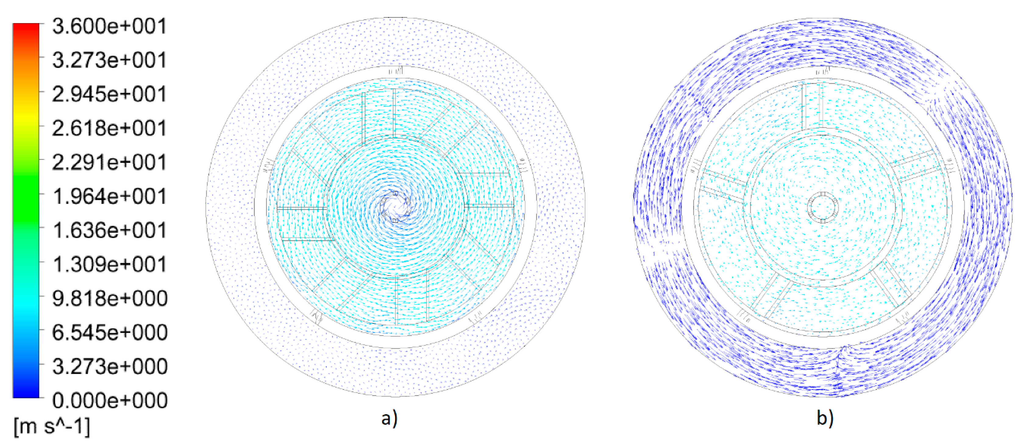
Figure 11.
Velocity vectors during combustion in plane 1 of the combustion chamber. (a) Optimized swirler, (b) baseline swirler.
Figure 11.
Velocity vectors during combustion in plane 1 of the combustion chamber. (a) Optimized swirler, (b) baseline swirler.
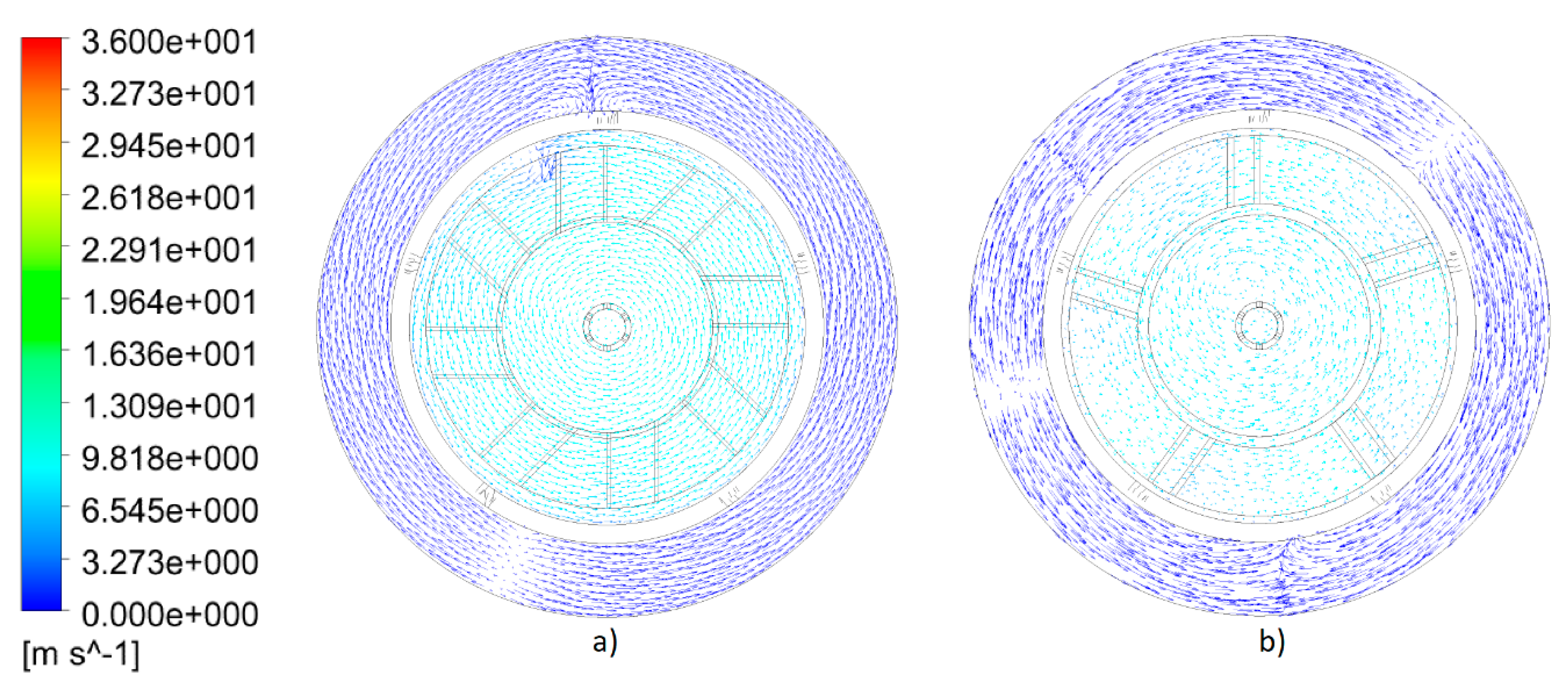
Figure 12.
Velocity vectors during combustion in plane 2 of the combustion chamber. (a) Optimized swirler, (b) baseline swirler.
Figure 12.
Velocity vectors during combustion in plane 2 of the combustion chamber. (a) Optimized swirler, (b) baseline swirler.
Figure 13.
Velocity vectors during combustion in plane 3 of the combustion chamber. (a) Optimized swirler, (b) baseline swirler.
Figure 13.
Velocity vectors during combustion in plane 3 of the combustion chamber. (a) Optimized swirler, (b) baseline swirler.
Figure 14.
Velocity vectors during combustion in plane 4 of the combustion chamber. (a) Optimized swirler, (b) baseline swirler.
Figure 14.
Velocity vectors during combustion in plane 4 of the combustion chamber. (a) Optimized swirler, (b) baseline swirler.
Figure 15.
Velocity vectors during combustion in plane 5 of the combustion chamber. (a) Optimized swirler, (b) baseline swirler.
Figure 15.
Velocity vectors during combustion in plane 5 of the combustion chamber. (a) Optimized swirler, (b) baseline swirler.
Figure 16.
Velocity vectors during combustion in plane 6 of the combustion chamber. (a) Optimized swirler, (b) baseline swirler.
Figure 16.
Velocity vectors during combustion in plane 6 of the combustion chamber. (a) Optimized swirler, (b) baseline swirler.
Figure 17.
Pressure drop of the air flow generated by the swirler. (a) Pressure at the optimized swirler inlet, (b) pressure at the optimized swirler outlet, (c) pressure at the baseline swirler inlet, (d) pressure at the baseline swirler outlet.
Figure 17.
Pressure drop of the air flow generated by the swirler. (a) Pressure at the optimized swirler inlet, (b) pressure at the optimized swirler outlet, (c) pressure at the baseline swirler inlet, (d) pressure at the baseline swirler outlet.
Figure 18.
Results of temperature profile in different xy planes of a CFD model of a combustion chamber with optimized swirler. (a) Plane 1 (10.50 cm), (b) plane 2 (14 cm), (c) plane 3 (17.60 cm), (d) plane 4 (23.60 cm), (e) plane 5 (26.60 cm), and (f) plane 6 (30 cm).
Figure 18.
Results of temperature profile in different xy planes of a CFD model of a combustion chamber with optimized swirler. (a) Plane 1 (10.50 cm), (b) plane 2 (14 cm), (c) plane 3 (17.60 cm), (d) plane 4 (23.60 cm), (e) plane 5 (26.60 cm), and (f) plane 6 (30 cm).
Figure 19.
Results of temperature profile in different xy planes of a CFD model of a combustion chamber with a baseline swirler. (a) Plane 1 (10.50 cm), (b) plane 2 (14 cm), (c) plane 3 (17.60 cm), (d) plane 4 (23.60 cm), (e) plane 5 (26.60 cm), and (f) plane 6 (30 cm).
Figure 19.
Results of temperature profile in different xy planes of a CFD model of a combustion chamber with a baseline swirler. (a) Plane 1 (10.50 cm), (b) plane 2 (14 cm), (c) plane 3 (17.60 cm), (d) plane 4 (23.60 cm), (e) plane 5 (26.60 cm), and (f) plane 6 (30 cm).
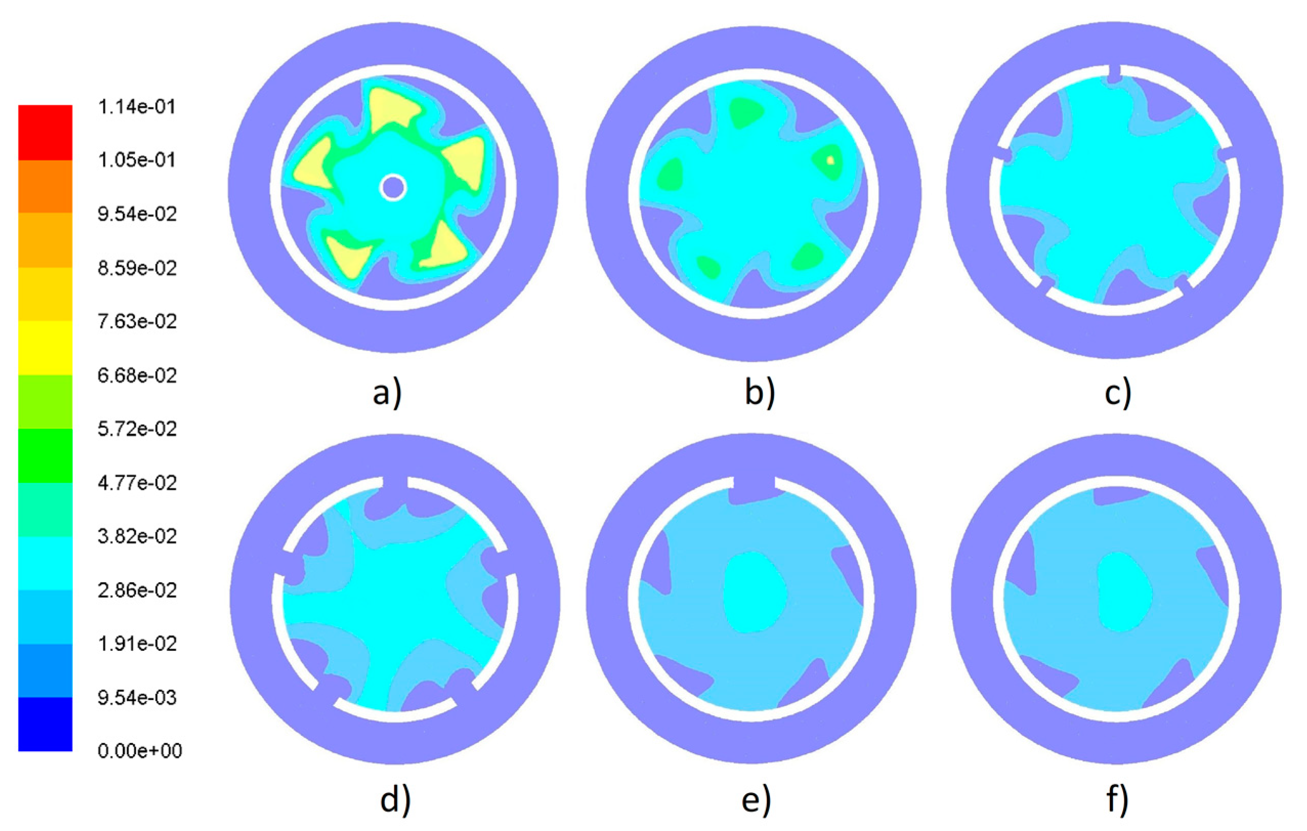
Figure 20.
Results of mole fraction of CO profile in different xy planes of a CFD model of a combustion chamber with an optimized swirler. (a) Plane 1 (10.50 cm), (b) plane 2 (14 cm), (c) plane 3 (17.60 cm), (d) plane 4 (23.60 cm), (e) plane 5 (26.60 cm), and (f) plane 6 (30 cm).
Figure 20.
Results of mole fraction of CO profile in different xy planes of a CFD model of a combustion chamber with an optimized swirler. (a) Plane 1 (10.50 cm), (b) plane 2 (14 cm), (c) plane 3 (17.60 cm), (d) plane 4 (23.60 cm), (e) plane 5 (26.60 cm), and (f) plane 6 (30 cm).
Figure 21.
Results of mole fraction of CO profile in different xy planes of a CFD model of a combustion chamber with a baseline swirler. (a) Plane 1 (10.50 cm), (b) plane 2 (14 cm), (c) plane 3 (17.60 cm), (d) plane 4 (23.60 cm), (e) plane 5 (26.60 cm), and (f) plane 6 (30 cm).
Figure 21.
Results of mole fraction of CO profile in different xy planes of a CFD model of a combustion chamber with a baseline swirler. (a) Plane 1 (10.50 cm), (b) plane 2 (14 cm), (c) plane 3 (17.60 cm), (d) plane 4 (23.60 cm), (e) plane 5 (26.60 cm), and (f) plane 6 (30 cm).
Figure 22.
Results of mole fraction of a CO2 profile in different xy planes of a CFD model of a combustion chamber with an optimized swirler. (a) Plane 1 (10.50 cm), (b) plane 2 (14 cm), (c) plane 3 (17.60 cm), (d) plane 4 (23.60 cm), (e) plane 5 (26.60 cm), and (f) plane 6 (30 cm).
Figure 22.
Results of mole fraction of a CO2 profile in different xy planes of a CFD model of a combustion chamber with an optimized swirler. (a) Plane 1 (10.50 cm), (b) plane 2 (14 cm), (c) plane 3 (17.60 cm), (d) plane 4 (23.60 cm), (e) plane 5 (26.60 cm), and (f) plane 6 (30 cm).
Figure 23.
Results of mole fraction of the CO2 profile in different xy planes of the CFD model of a combustion chamber with a baseline swirler. (a) Plane 1 (10.50 cm), (b) plane 2 (14 cm), (c) plane 3 (17.60 cm), (d) plane 4 (23.60 cm), (e) plane 5 (26.60 cm), and (f) plane 6 (30 cm).
Figure 23.
Results of mole fraction of the CO2 profile in different xy planes of the CFD model of a combustion chamber with a baseline swirler. (a) Plane 1 (10.50 cm), (b) plane 2 (14 cm), (c) plane 3 (17.60 cm), (d) plane 4 (23.60 cm), (e) plane 5 (26.60 cm), and (f) plane 6 (30 cm).
Figure 24.
Prototype of combustion chamber used in experimental tests.
Figure 24.
Prototype of combustion chamber used in experimental tests.
Figure 25.
Schematic view of different positions of thermocouple in peephole 1 (left): (a) Position 1, (b) position 2, (c) position 3, and (d) position 4, and peephole 2 (right): (e) position 1, (f) position 2, (g) position 3, and (h) position 4.
Figure 25.
Schematic view of different positions of thermocouple in peephole 1 (left): (a) Position 1, (b) position 2, (c) position 3, and (d) position 4, and peephole 2 (right): (e) position 1, (f) position 2, (g) position 3, and (h) position 4.
Figure 26.
Measurements of temperatures in four different positions of the combustion chamber.
Figure 26.
Measurements of temperatures in four different positions of the combustion chamber.
Figure 27.
Temperature in peephole 1 obtained using a CFD model and experimental tests.
Figure 27.
Temperature in peephole 1 obtained using a CFD model and experimental tests.
Figure 28.
Temperature in peephole 2 obtained using a CFD model and experimental tests.
Figure 28.
Temperature in peephole 2 obtained using a CFD model and experimental tests.
Figure 29.
Lateral thermal image of the combustion chamber.
Figure 29.
Lateral thermal image of the combustion chamber.
Figure 30.
Cross thermal image of the combustion chamber outlet.
Figure 30.
Cross thermal image of the combustion chamber outlet.
Table 1.
Recommended values of geometrical parameters for the swirler design.
Table 1.
Recommended values of geometrical parameters for the swirler design.
| Geometrical Parameter | Minimum | Maximum |
|---|
| θ | 30° | 60° |
| tv | 0.7 mm | 1.5 mm |
| nv | 8 | 16 |
| ksw | 1.15 (curved vane) | 1.3 (flat vane) |
Table 2.
Limits of the geometrical parameters used in the genetic algorithms for the swirler design.
Table 2.
Limits of the geometrical parameters used in the genetic algorithms for the swirler design.
| Variable | Minimum | Maximum |
|---|
| θ | 10° | 60° |
| tv | 0.7 mm | 1.5 mm |
| nv | 8 | 16 |
Table 3.
Range of restrictions for swirler design using genetic algorithms.
Table 3.
Range of restrictions for swirler design using genetic algorithms.
| Restrictions | Minimum | Maximum |
|---|
| Sn | 0.6 | 2.5 |
| Dhub/Dsw | 0.4 | 0.6 |
| Dhub | 0.05 m | 0.0588 m |
Table 4.
Values of different parameters considered in the objective function of the swirl number.
Table 4.
Values of different parameters considered in the objective function of the swirl number.
| Parameters | Value |
|---|
| Internal diameter of the case | 0.157 m |
| Diameter of combustor | 0.107 m |
| Minimum diameter of diffuser | 0.06 m |
| Air density | 1.16 kg/m3 |
| Vane shape factor | 1.15 |
| Air mass flow | 4.398 × 10⁻² kg/s |
| Percentage of air entering the combustor | 70% |
| Combustor pressure drop relative to dynamic pressure | 20 Pa |
| Ratio of the combustor pressure drop to the combustor inlet | 0.06 |
| Gas constant | 286.9 N m/kg |
| Temperature of incoming air | 303.15 K |
Table 5.
Values of optimum swirler design obtained by genetic algorithm.
Table 5.
Values of optimum swirler design obtained by genetic algorithm.
| θ | nv | tv | Dhub | Depth |
|---|
| 18° | 8 | 0.001 m | 0.0576 m | 0.039 m |
Table 6.
Boundary conditions for numerical analysis.
Table 6.
Boundary conditions for numerical analysis.
| Variable | Value |
|---|
| Air inlet pressure | 2100 (Pa) |
| Mass air flow | 4.398 × 10⁻² (kg/s) |
| Air temperature | 303.15 (K) |
| Fuel inlet pressure | 2100 (Pa) |
| Mass fuel flow | 2.95 × 10⁻⁴ (kg/s) |
| Fuel temperature | 300.15 (K) |
| Combustion chamber outlet pressure | 375 (kg/s) |
| Wall temperature | 300 (K) |
Table 7.
Comparative table of the design parameters of the swirlers.
Table 7.
Comparative table of the design parameters of the swirlers.
| | θ | nv | tv | Dhub | Depth | Sn |
|---|
| Optimized swirler model | 18° | 8 | 0.001 m | 0.0576 m | 0.039 m | 2.48 |
| Baseline swirler model | 12° | 5 | 0.0015 m | 0.06 m | 0.03 m | 0.18 |

 ,
, 


