An Islanding Detection Technique for Inverter-Based Distributed Generation in Microgrids


1
School of Technology and Innovations, University of Vaasa, Wolffintie 34, FI-65200 Vaasa, Finland
2
Department of Electrical Engineering, Faculty of Basic Sciences and Engineering, Gonbad Kavous University, Gonbad Kavous 49717-99151, Iran
3
Department of Electronics and Electrical Engineering, University of Strathclyde, Glasgow G1 1XW, UK
*
Author to whom correspondence should be addressed.
Energies 2021, 14(1), 130; https://doi.org/10.3390/en14010130
Submission received: 23 November 2020
/
Revised: 17 December 2020
/
Accepted: 22 December 2020
/
Published: 29 December 2020
(This article belongs to the Special Issue Smart Grids and Flexible Energy Systems)
Abstract
:This article proposes a new passive islanding detection technique for inverter-based distributed generation (DG) in microgrids based on local synchrophasor measurements. The proposed method utilizes the voltage and current phasors measured at the DG connection point (point of connection, PoC). In this paper, the rate of change of voltages and the ratio of the voltage and current magnitudes (VoI index) at the PoC are monitored using micro-phasor measurement units. The developed local measurements based decentralized islanding detection technique is based on the VoI index in order to detect any kind of utility grid frequency fluctuations or oscillations and distinguishing them from islanding condition. The simulation studies confirm that the proposed scheme is accurate, robust, fast, and simple to implement for inverter-based DGs.
1. Introduction
In recent decades, the significant penetration of distributed generations (DGs) in distribution networks has created new challenges in protection of these networks. One of the most well-known of these challenges is the detection of islanding conditions [1]. During an islanding event, a part of the distribution network with DGs is unintentionally separated from the main grid, often caused by protection relays and circuit breakers operation [2,3]. The islanding condition should be detected appropriately. Otherwise, it can cause successive damages to DGs and their equipment. In addition, non-detected islanding condition may result in voltage and frequency deviations from the standard ranges, improper operation of protections, and hazards for personnel [4].
The microgrid (MG) is one of the energy provision concepts that has attracted a lot of attention with the increasing penetration of DGs [5]. It is worth noting that the islanding conditions should be correctly detected in MGs as well [6]. In view of the fact that the operation, control, safety, and protection strategies would be different in intentional island mode and grid-connected mode [7,8,9,10], it is also necessary to implement an efficient scheme to detect the unintentional islanding conditions in MGs. The following criteria should be considered for designing an efficient islanding detection scheme:
- It should be able to detect islanding events in a wide range of operational conditions.
- It should not operate incorrectly for non-islanding disturbances, e.g., short-circuit faults and load changes.
- It should be as low-cost as possible.
- It should be as simple as possible.
- It should be compatible with and easily implementable in most of the existing infrastructures and systems.
So far, many schemes have been proposed for islanding detection in MGs, which can be categorized into remote and local schemes [6,14]. Remote islanding detection schemes need telecommunication channels and infrastructures, since they operate based on measurements and information received from both the utility grid and MG sides. This requirement increases the cost and complexity of these schemes compared to local islanding detection schemes that need only local measurements and information. Local schemes can also be categorized into passive, active, and hybrid schemes [6,14]. Passive schemes decide based on the local measurements and predefined thresholds without any changes in MGs, while active schemes usually inject perturbations to MGs to decide based on the consequent changes in local measurements [15,16]. A hybrid scheme is a combination of passive and active schemes [17,18]. Among the various local islanding detection schemes, passive schemes have the lowest cost, lowest complexity, and highest detection speed and, unlike active schemes, do not have negative effects on power quality [6]. However, the non-detection zone of passive schemes is usually higher compared to active and hybrid schemes [19]. This shortcoming may be even more pronounced in MGs containing inverter-based DGs. Some researchers have attempted to improve the performance of local passive islanding detection schemes for MGs containing inverter-based DGs.
Merino et al. [20] designed a passive islanding detection scheme considering the magnitude of the fifth harmonic voltage. The test results showed that this low-cost scheme [20] can correctly detect the islanding events in MGs with significant penetration of inverter-based DGs. However, it may not apply to MGs with only synchronous DGs due to its dependency on a specific harmonic order. Also, the stability of this scheme [20] has not been examined for non-islanding disturbances like short-circuit faults.
Khamis et al. [21] proposed a passive islanding detection scheme based on the locally measured three-phase voltage signals, phase-space feature extraction technique, and the ensemble of extreme learning machine classifiers. The test results confirmed the effective detection performance of this scheme [21] in MGs, including synchronous and inverter-based DGs. The need for many training patterns in the preparation stage is one of the disadvantages of this scheme [21].
Mlakić et al. [22] designed a passive islanding detection scheme for MGs with inverter-based DGs by employing the adaptive neuro-fuzzy inference system and some locally measured input data. They considered the input data, voltage’s root mean square value, voltage’s total harmonic distortion, current’s root mean square value, current’s total harmonic distortion, active power, reactive power, and frequency. Baghaee et al. [23] also used these features as inputs to a support vector machine classifier for passive detection of the islanding events in MGs with inverter-based DGs. Despite the good test performance of these schemes [22,23], the need for a considerable number of training patterns in various conditions is one of the challenges to their implementation.
Xie et al. [24] designed a passive islanding detection scheme based on the equivalent resistance’s change-of-rate. The simulation results revealed the good performance of this scheme [24] in MGs with synchronous and inverter-based DGs under various islanding and non-islanding events. However, the stability of this scheme [24] against various disturbances needs more investigation. Abdelsalam et al. [25] presented a passive islanding detection scheme for MGs with synchronous and inverter-based DGs using the locally measured three-phase voltage and current signals, discrete Fourier transform, and the long short-term memory classifier. Although the comprehensive test results showed the promising performance of this scheme [25] in a wide range of conditions, the need for several training patterns is one of the difficulties toward its implementation. Despite the introduction of these innovative passive schemes for MGs with inverter-based DGs, the problem is still a hot topic and needs more improvement in terms of accuracy, speed, and applicability.
This paper proposes a new passive islanding detection technique for MGs with synchronous and inverter-based DGs. This technique operates based on the locally measured voltage and current phasors at the DGs’ output terminals. The scheme is fully compatible with decentralized control strategies, since it can be independently and locally executed at each inverter-based DG’s output terminal. The ratio of the magnitudes of the voltage and current (the VoI index) at the point of DG connection is introduced in this paper. Then, an islanding detection technique based on the VoI index is introduced for distinguishing an islanding condition from non-islanding event in MGs. The proposed scheme is validated by PSCAD/EMTDC simulation-based study. The results are proven that the scheme is robust, fast, and simple to implement in the MGs.
In the rest of this paper, the proposed passive islanding detection technique is presented in Section 2. Next, in Section 3, a test system model of MG with synchronous and inverter-based DGs is presented. Afterward, the results are discussed in Section 4. Finally, this paper is concluded in Section 5.
2. Proposed Passive Islanding Detection Technique
The proposed passive islanding detection method utilizes voltage and current phasors of micro-phasor measurement units (µPMUs), which are introduced for monitoring purposes of distribution networks. It is assumed that the µPMUs are installed in the DG connection points (PoC) in the distribution network. The proposed local and decentralized detection method is applicable for distribution networks with different penetration levels of inverter-based generation.
2.1. Concept of the Proposed Method
The proposed method is based on monitoring of the power system parameters, such as voltage and current, with µPMUs installed in DGs connection points (PoC) in the distribution network. It is necessary to select critical parameters and their rate of changes to create a new real-time islanding detection strategy. In this way, the rate of change of the voltage (RoCoV) will be also obtained as an input signal for islanding detection purpose from the µPMUs at PoC. Therewith, the voltage and current, in PoC, are also monitored to distinguish the fault cases from the islanding event. To illustrate the concept of the proposed islanding detection method and the reason for selecting RoCoV as the indicator for islanding detection, a simple test system model with 2 buses was created as shown in Figure 1. In this simple two-bus network, |VDG| is the voltage magnitude of the bus where the DG is connected (at PoC) and |VMG| represents the voltage magnitude of the MG side which is actually connected to the main grid. As it is obvious, Equations (1)–(4) can be used to obtain |VDG|.
Equation (3) can be obtained from Equations (1) and (2):
In Equation (4), if |VMG| is assumed to be equal to 1 p.u., then Equation (5) can be achieved:
In the distribution network, it is obvious that, for the line parameters, R is comparable with X, and in such cases contrarily from transmission line parameters, R cannot be ignored. Actually, in the transmission lines, the X/R ratio is larger than the distribution lines. This ratio will be very small and may be smaller than 1 in the case of underground cables in distribution networks meaning that, for the line parameters, X has a small value in distribution lines against R. Hence, by drawing the phasor diagram of Equation (5), VDG can be obtained as presented in Figure 2.
The proposed strategy was created based on the RoCoV to detect any phenomena of the MG. In fact, Figure 3 presents a new condition of phasor diagram of voltages after small changes in the active and reactive power of power system, (ΔP and ΔQ are presented as the changing of active and reactive power in this figure, respectively). It can be seen that the magnitude of the voltage in the DG side will be affected after changes in either the active or reactive power. Hence, the equations and phasor diagram of the test system demonstrate that the RoCoV is valuable for monitoring any event in the power system. In Figure 3, small changes in ΔP and ΔQ are presented, and it can be seen that the magnitude of voltage in the DG side (at PoC) can be affected by any changes in ΔP and ΔQ. The new value of voltage (|VDG|’ in Figure 3) is presented in the form of the dashed line after a small change in ΔP and ΔQ, and the previous value of |VDG|, before any changes, is also illustrated for evaluation.
It can be seen that any changes in |VDG| due to changes in the active and reactive power are valuable for islanding detection purposes and, in particular, the RoCoV would be a useful quantity to apply. It should be noted that even in the case of zero-transferring power between MG and the main grid, there is always a change in |VDG| due to changes in the MG configuration.
2.2. New VoI Index
To enable enhanced passive islanding detection, a new index is proposed in this article in order to distinguish islanding condition from any fluctuations and oscillations in the grid side, e.g., faults and switching events of large loads in the MG. The new index is defined as the ratio between the magnitudes of voltage and current at the PoC of any kind of inverter-based DG. This index is named as the VoI index and it can be calculated easily using the Equation (6) for all three phases.
As mentioned in Section 1, the islanding detection function should be fast, reliable, and selective, as well as low-cost and simple. The algorithm proposed in this article has only a few steps. Therefore, it will be simple to implement and execute in real time. This algorithm only relies on the voltage and current data locally sampled at a low rate using common measurement devices. Hence, it will also be cost-effective, since it does not require additional communication infrastructure or special measurement devices.
2.3. Proposed Algorithm for Islanding Detection Technique
The flowchart of the proposed islanding detection technique is illustrated in Figure 4. In this proposed islanding detection technique, µPMU is assumed to be installed for monitoring the voltage and current phasors of the inverter-based DGs in the connection point with the microgrid (at the PoC). Phase-to-ground voltages and line currents of all 3 phases were used in this method. At first, it was necessary to check the fault condition and distinguish the fault from the other events. For this purpose, symmetrical components of the voltage were calculated. The currents in all phases and symmetrical components of the voltage were used to detect any fault condition and distinguish it from the other phenomenon. After that, the RoCoVs and the VoI index at the PoC were calculated, where Va(t), Vb(t), Vc(t), Ia(t), Ib(t), and Ic(t) were the fundamental phase quantities of voltages and currents, respectively. A sampling frequency of 1 kHz was used to calculate the RoCoVs and VoI index, with a sliding window concept. A set of samples that is required to estimate and calculate these indexes was included in the sliding window. However, it is worth mentioning that the number of samples in the sliding window was fixed and, by obtaining new samples from µPMU, the oldest samples were discarded from the window. For the next step, calculated values of RoCoVs were compared with the preset threshold values, and if this variation became greater than certain level, then the proposed algorithm proceeded to distinguish any kind of rapid utility grid frequency fluctuations or oscillations, switching events, such as the connection/disconnection of large loads from the islanding event as a next step.
In order to assess the event, the magnitude of the new index was utilized in the proposed method and monitored for duration of around 0.1 s until 0.6 s (right after the event is detected). It is obvious that, after any events, the value of VoI index will be changed. However, for any kind of switching events, such as the connection/disconnection of large loads, this value will be changed and then will be almost constant right after the event. In the case of the islanding condition, as opposed to the switching event, the value of the VoI index will keep on changing for the mentioned monitoring time and it will be settled after around 2 s or even more, mainly depending on the system configuration. By implementing the new index, islanding event can be recognized. As a result, the proposed algorithm can easily distinguish between the switching event and islanding condition within less than 2 s, in accordance with IEEE Std. 1547-2018 [26]. On the other hand, the proposed islanding detection technique is compatible with the grid code requirements of DG units (e.g., in terms of their fault-ride-through, frequency-ride-through, low-voltage-ride-through, and rate-of-change of frequency ride-through capability).
The selection of the threshold value requires great attention, and it is one of the main challenges of all passive islanding detection methods. In the proposed method, the threshold value for RoCoV needs to be adjusted. However, it is only to detect any kind of system disturbance or event (such as an islanding or non-islanding event). Then, after the detection/function start, the proposed method distinguishes an islanding conditions from non-islanding events. This process does not depend on any threshold value.
3. Test System Model and Case Studies
This section describes the test system model which is used for the investigation of the proposed islanding detection method along with the definition of the test case studies.
3.1. Test System Model
A distribution network model, described by the authors of [27], was used to prove the concept of the proposed islanding detection method. The single line diagram of the test system model is presented in Figure 5. In this test system model, the PV is connected to bus number 12, the synchronous generator is connected to bus number 33, and the point of common coupling (PCC) with the grid is bus number 30 via a 4 MVA 132 kV/11 kV transformer. The test system consists of 33 buses. The 26 active loads are considered as static impedances in the simulations, which utilizes a 2.5 MVA mini-hydro generation unit and a 2.5 MW PV array panel as the main renewable energy resource units. In this test system model, a total load of 3.09 MW was simulated in peak loading condition (including distribution line losses).
3.2. Test Cases Studies
It is important to validate the proposed method with a variety of islanding and non-islanding case studies in the test system model. In order to fulfill the mentioned statement, the following case studies were chosen for the validation and investigation of the proposed method. These case studies are presented in Table 1. Furthermore, 2 different scenarios were investigated in each case. In these scenarios, different active and reactive power mismatches were chosen, as presented in Figure 6 and Figure 7. The active and reactive power mismatches were 0.0538 MW and 0.084 MVAr in scenario A and −0.538 MW and −0.0328 MVAr in scenario B, respectively.
4. Results and Discussion
The proposed islanding detection technique was considered under the following operating conditions: (a) Islanding event and (b) non-islanding events, such as single or three-phase to ground fault, the sudden connection of loads, and capacitor switching in grid connection mode.
4.1. Islanding Event
In this case, which should be detected by the proposed method as either an intentional or intentional islanding event, disconnection of the grid is simulated by opening the circuit breaker at PCC (which is located between buses No. 30 and 31). In this event, the distribution network may continue to support the customers’ loads. According to IEEE Std. 1547-2018, participating DGs may have to adjust several control and protection settings in order to meet the adaptive protection and control settings for operating in an intentional islanding condition, which was not in the scope of this article.
The active and reactive power of the DGs and grid during this case study event are presented in Figure 6a,b, respectively. The active power and reactive power, prior to the islanding condition, were 0.0538 MW and 0.084 MVAr for scenario A and −0.538 MW and −0.0328 MVAr for scenario B, respectively. The negative value indicates that the power was injected into the grid from the MG.
As it is presented in Figure 6c, the RoCoVs clearly showed that there was an occurrence of an event at t = 0.5 s. The sharp variation of the RoCoVs indicated the right time to define whether the MG was islanded or not. It was worth investigating whether the event was due to load changes or islanding event. At this stage, the proposed VoI index could assess the event. The graph of the VoI index is illustrated in Figure 6d, and it can be seen clearly that, after sharp changes in the VoI index, the changes were settled and continued almost for 1 s. Normally, even for the scenarios where power transmission between grid and MG is near to zero, these changes are much larger than the changes occurring in load variation cases.
The results of the proposed method are shown in Figure 7. As it can be seen, the proposed method successfully detected an islanding event within 0.149 s and 0.108 s after event for scenario A and scenario B, respectively. The islanding detection signal is presented in red and blue color for scenario A and B, respectively, in this figure.
4.2. Single Phase to Ground Fault
In order to validate the proposed method, the single line to ground fault was simulated in different locations of the test system, and the furthermost bus from the PV was selected for presentation. System parameters, such as the active and reactive power of the DGs and grid, were monitored before and after the event and are illustrated in Figure 8a,b, respectively. As it is obvious, there was a jump in the active and reactive power during the single line to ground fault event at t = 0.5 s.
In this case study, RoCoV was detected during the event at t = 0.5 s as shown in Figure 8c. As a next step, it is required to check the symmetrical component of the voltage. Symmetrical components of the voltages for scenario A and B are presented in Figure 8d,e, respectively. It can be seen that, in both scenarios, a fault condition was detected due to changes in negative sequence value of the voltage. In the proposed method, the fault condition was detected right after the changes in RoCoVs, and the fault detection signals for both scenarios are presented in Figure 9.
4.3. Three-Phase to Ground Fault
It is important to validate the proposed islanding detection technique against the three-phase to ground fault event. In this regard, the three-phase to ground fault event was simulated in different locations of the test system, and the furthermost bus from the PV was selected for presentation in the content of this article. System parameters, such as the active and reactive power of the DGs and grid, were monitored before and after the event and are illustrated in Figure 10a,b, respectively. In this case study, it can be seen that there was an extreme change in both the active and reactive power due to the three-phase to ground fault event at t = 0.5 s.
RoCoVs values of scenario A and B are also illustrated in Figure 10c. In this case study, symmetrical components of the voltage are presented in Figure 10d,e for scenario A and B, respectively. A faulty condition was detected due to changes in negative sequence value of the voltage. Thus, the signal of fault detection was changed from zero to one as depicted in Figure 11. It can be seen that the proposed method was able to successfully distinguish any kind of the faulty conditions from islanding condition.
4.4. Sudden Connection of Load
This case was studied to prove the performance of the proposed method under non-islanding conditions such as the sudden connection of loads in the MGs. The sudden connection of loads has been studied for different ranges of loads and only two scenarios are presented here. As it is shown in Figure 12a,b, the active power and reactive power of the DGs and grid changed due to the sudden connection of the load. In this case study, the load was connected at t = 0.5 s with a value of P = 0.6 MW and Q = 0.6 MVAr for the two scenarios, A and B. It should be noted that a 20% increment of the total load was simulated for this case study, and the proposed islanding detection technique was expected to recognize any kind of load changes in the MG from islanding event.
From Figure 12c, it can be seen that occurrence of the event was detected at t = 0.5 s due to significant changes in the RoCoVs. As mentioned earlier, the proposed algorithm checks the VoI index whenever an event is detected. The calculated value of the VoI index for this case study is presented in Figure 12d. It can be seen that, contrarily to the islanding event presented in case study 1, the VoI index settled right after the event into a new value and there was not any other changes in the magnitude of the VoI index. In Figure 12d, it can be seen that the VoI index fluctuated around 0.05, and this fluctuation was not really significant when compared to case 1. The islanding detection signal for this case is presented in Figure 13, and it was proven that the proposed method did not detect any islanding or fault event in the test system in this case.
4.5. Capacitor Switching
To study the performance of the proposed method, capacitor switching was also simulated as a non-islanding event, and the proposed method was expected to differentiate it from the islanding condition. In this case, a capacitor with the rated value of 0.6 MVAr was selected for connection into the MG. The reactive power generation of DGs and the grid are depicted in Figure 14a, before and after the event. From Figure 14b, it can be seen that there an event occurred at t = 0.5 s due to rapid changes in RoCoVs. Next, it was investigated whether the event was an islanding event or non-islanding event. At this stage and right after the event, the VoI index which is depicted in Figure 14c, was used to distinguish the event. From this figure, it can be clearly seen that the VoI index remained almost constant after reaching the new value. Hence, it can be concluded that the event was a non-islanding event, and the Boolean signal for islanding detection was equal to zero, as presented in Figure 15.
4.6. Non-Detection Zone
In most of the passive islanding detection techniques, the non-detection zone (NDZ) is declared as a region in which the islanding technique fails to detect islanding phenomenon of MG within 2 s. This region is usually defined by the percentage of the MG power imbalance. The proposed islanding detection technique was evaluated for more than 198 different scenarios to determine the NDZ. Various scenarios of active and reactive power imbalance within MG were simulated to determine the NDZ of the proposed technique. In this regard, the NDZ of the proposed islanding detection technique is depicted in Figure 16 and compared with the recent published methods [24,28]. The proposed method was unable to detect the islanding event for the imbalance power region of [−0.5%, 0.5%] and [−0.5%, 0.5%], referring, respectively, to active and reactive power mismatches.
5. Conclusions
A new passive islanding detection technique for inverter-based DGs was proposed and investigated in this paper. The developed method is based on the rate of change of voltage (RoCoV) and the ratio of voltage and current magnitudes (VoI) at PoC in order to detect all kind of events and distinguish them from islanding condition. The main advantages of the proposed method are:
- (1)
- It is quick enough to detect an islanding event in less than 2 s, which is a requirement according to IEEE Std. 1547-2018.
- (2)
- The NDZ is narrow when compared to other traditional passive methods.
- (3)
- It has a decentralized operation principle, which may simplify and reduce the cost of implementation.
- (4)
- It is compatible with traditionally used distribution network infrastructures.
- (5)
- It is robust robust against system short circuit faults and load switching, as well as both stable and unstable power swings.
It can be concluded that the proposed islanding detection technique is promising for detecting islanding events even with very low values of active and reactive power mismatches. Moreover, it can be easily implemented in different kind of distribution systems.
Author Contributions
Conceptualization, M.K. and H.L.; methodology, M.K.; software, M.K. and M.F.; validation, M.K.; formal analysis, Q.H.; investigation, M.K. and Q.H.; resources, K.K.; data curation, M.K.; writing—original draft preparation, M.K.; writing—review and editing, M.F., Q.H., H.L. and K.K.; visualization, M.K.; supervision, K.K.; project administration, M.K.; funding acquisition, K.K. All authors have read and agreed to the published version of the manuscript.
Funding
This work was carried out mainly in the Profi4/WP2 project with the financial support provided by the Academy of Finland. Some parts of this work were done in the SolarX research project with the financial support provided by the Business Finland with Grant No. 6844/31/2018. The financial support provided through these research projects is highly acknowledged.
Data Availability Statement
Data sharing is not applicable to this article since no new data were created or analyzed in this study.
Conflicts of Interest
The authors declare no conflict of interest.
Nomenclature
| DG | Distributed Generation |
| MG | Microgrid |
| NDZ | Non-Detection Zone |
| PCC | Point of Common Coupling |
| PMU | Phasor Measurement Unit |
| PoC | Point of DG Connection |
| RoCoV | Rate of Changes of the Voltage |
| VoI | The ratio of the magnitudes of the voltage and current |
| µPMU | micro-Phasor Measurement Unit |
References
- Kim, M.-S.; Haider, R.; Cho, G.-J.; Kim, C.-H.; Won, C.-Y.; Chai, J.-S. Comprehensive review of islanding detection methods for distributed generation systems. Energies 2019, 12, 837. [Google Scholar] [CrossRef] [Green Version]
- Subramanian, K.; Loganathan, A.K. Islanding detection using a micro-synchrophasor for distribution systems with distributed generation. Energies 2020, 13, 5180. [Google Scholar] [CrossRef]
- Kumar, S.A.; Subathra, M.S.P.; Kumar, N.M.; Malvoni, M.; Sairamya, N.J.; George, S.T.; Suviseshamuthu, E.S.; Chopra, S.S. A novel islanding detection technique for a resilient photovoltaic-based distributed power generation system using a tunable-q wavelet transform and an artificial neural network. Energies 2020, 13, 4238. [Google Scholar] [CrossRef]
- Bekhradian, R.; Davarpanah, M.; Sanaye-Pasand, M. Novel approach for secure islanding detection in synchronous generator based microgrids. IEEE Trans. Power Deliv. 2019, 34, 457–466. [Google Scholar] [CrossRef]
- Singh, A.R.; Lei, D.; Kumar, A.; Singh, R.; Meena, N.K. Microgrid System. In Microgrid: Operation, Control, Monitoring and Protection; Ray, P., Biswal, M., Eds.; Springer: Singapore, 2020; pp. 1–25. [Google Scholar] [CrossRef]
- Hosseinzadeh, M.; Rajaei Salmasi, F. Islanding fault detection in microgrids—A survey. Energies 2020, 13, 3479. [Google Scholar] [CrossRef]
- Zheng, T.; Yang, H.; Zhao, R.; Kang, Y.C.; Terzija, V. Design, evaluation and implementation of an islanding detection method for a micro-grid. Energies 2018, 11, 323. [Google Scholar] [CrossRef] [Green Version]
- Ghalavand, F.; Alizade, B.A.M.; Gaber, H.; Karimipour, H. Microgrid islanding detection based on mathematical morphology. Energies 2018, 11, 2696. [Google Scholar] [CrossRef] [Green Version]
- Pinto, J.O.C.P.; Moreto, M. Protection strategy for fault detection in inverter-dominated low voltage AC microgrid. Electr. Power Syst. Res. 2021, 190, 106572. [Google Scholar] [CrossRef]
- Zarei, S.F.; Mokhtari, H.; Blaabjerg, F. Fault detection and protection strategy for islanded inverter-based microgrids. IEEE J. Emerg. Sel. Top. Power Electron. 2019, 1. [Google Scholar] [CrossRef]
- IEEE Standard for Interconnecting Distributed Resources with Electric Power Systems; IEEE Std 1547-2003; IEEE: Piscataway, NJ, USA, 2003.
- IEEE Recommended Practice for Utility Interface of Photovoltaic (PV) Systems; IEEE Std 929-2000; IEEE: Piscataway, NJ, USA, 2000.
- Photovoltaic (PV) Systems-Characteristics of the Utility Interface; IEC Std 61727; IEC: Geneva, Switzerland, 2004.
- Mishra, M.; Chandak, S.; Rout, P.K. Taxonomy of Islanding detection techniques for distributed generation in microgrid. Renew. Energy Focus 2019, 31, 9–30. [Google Scholar] [CrossRef]
- Bakhshi-Jafarabadi, R.; Sadeh, J. New voltage feedback-based islanding detection method for grid-connected photovoltaic systems of microgrid with zero non-detection zone. IET Renew. Power Gener. 2020, 14, 1710–1719. [Google Scholar] [CrossRef]
- Bakhshi-Jafarabadi, R.; Sadeh, J.; Popov, M. Maximum power point tracking injection method for islanding detection of grid-connected photovoltaic systems in microgrid. IEEE Trans. Power Deliv. 2020, 1. [Google Scholar] [CrossRef]
- Paiva, S.C.; de Araujo Ribeiro, R.L.; Alves, D.K.; Costa, F.B.; Rocha, T.D. A wavelet-based hybrid islanding detection system applied for distributed generators interconnected to AC microgrids. Int. J. Electr. Power Energy Syst. 2020, 121, 106032. [Google Scholar] [CrossRef]
- Chen, X.; Li, Y.; Crossley, P. A novel hybrid islanding detection method for grid-connected microgrids with multiple inverter-based distributed generators based on adaptive reactive power disturbance and passive criteria. IEEE Trans. Power Electron. 2019, 34, 9342–9356. [Google Scholar] [CrossRef]
- Zheng, X.; Zhang, R.; Chen, X.; Sun, N. Improved three-phase AFD islanding detection based on digital control and non-detection zone elimination. Energies 2018, 11, 2421. [Google Scholar] [CrossRef] [Green Version]
- Merino, J.; Mendoza-Araya, P.; Venkataramanan, G.; Baysal, M. Islanding detection in microgrids using harmonic signatures. IEEE Trans. Power Deliv. 2015, 30, 2102–2109. [Google Scholar] [CrossRef] [Green Version]
- Khamis, A.; Xu, Y.; Dong, Z.Y.; Zhang, R. Faster detection of microgrid islanding events using an adaptive ensemble classifier. IEEE Trans. Smart Grid 2018, 9, 1889–1899. [Google Scholar] [CrossRef]
- Mlakić, D.; Baghaee, H.R.; Nikolovski, S. A novel ANFIS-based islanding detection for inverter-interfaced microgrids. IEEE Trans. Smart Grid 2019, 10, 4411–4424. [Google Scholar] [CrossRef]
- Baghaee, H.R.; Mlakić, D.; Nikolovski, S.; Dragicčvić, T. Anti-islanding protection of PV-based microgrids consisting of PHEVs using SVMs. IEEE Trans. Smart Grid 2020, 11, 483–500. [Google Scholar] [CrossRef]
- Xie, X.; Huang, C.; Li, D. A new passive islanding detection approach considering the dynamic behavior of load in microgrid. Int. J. Electr. Power Energy Syst. 2020, 117, 105619. [Google Scholar] [CrossRef]
- Abdelsalam, A.A.; Salem, A.A.; Oda, E.S.; Eldesouky, A.A. Islanding detection of microgrid incorporating inverter based DGs using long short-term memory network. IEEE Access 2020, 8, 106471–106486. [Google Scholar] [CrossRef]
- IEEE Standard for Interconnection and Interoperability of Distributed Energy Resources with Associated Electric Power Systems Interfaces; IEEE Std 1547-2018 (Revision of IEEE Std 1547-2003); IEEE: Piscataway, NJ, USA, 2018; pp. 1–138. Available online: https://ieeexplore.ieee.org/document/8332112 (accessed on 6 April 2018).
- Karimi, M.; Azizipanah-Abarghooee, R.; Uppal, H.; Hong, Q.; Booth, C.; Terzija, V. Smart Integrated Adaptive Centralized Controller for Islanded Microgrids under Minimized Load Shedding. In Proceedings of the 2017 5th International Istanbul Smart Grid and Cities Congress and Fair (ICSG), Istanbul, Turkey, 19–21 April 2017. [Google Scholar]
- Raza, S.; Mokhlis, H.; Arof, H.; Laghari, J.A.; Mohamad, H. A sensitivity analysis of different power system parameters on islanding detection. IEEE Trans. Sustain. Energy 2016, 7, 461–470. [Google Scholar] [CrossRef]
Figure 1.
Simple 2-bus power system model to prove the concept of the islanding detection method.

Figure 2.
Phasor diagram of voltages in simple power system model.
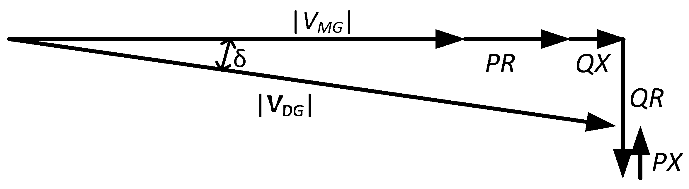
Figure 3.
Phasor diagram of voltages in islanding condition by changes in P and Q.
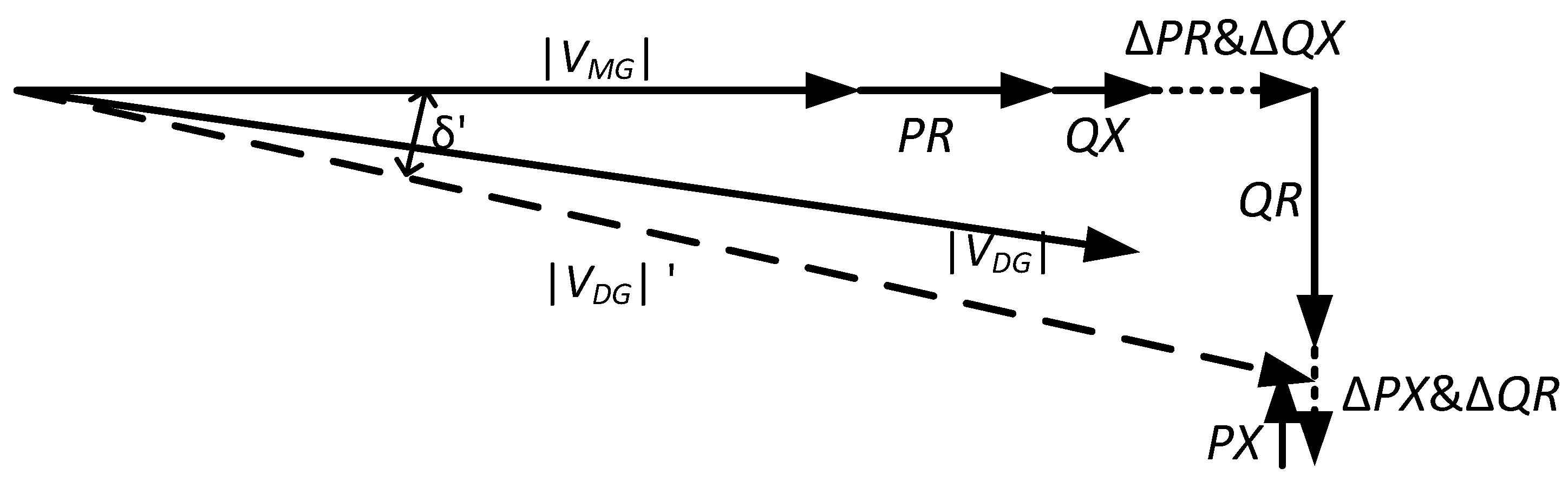
Figure 4.
The flowchart of the proposed passive islanding detection technique.

Figure 5.
Single line diagram of the test system model.

Figure 6.
Islanding event case study (a) Active power outputs of distributed generations (DGs) and grid; (b) Reactive power outputs of DGs and grid; (c) Rate of change of the voltages for three phases at the point of connection (PoC) of the photovoltaic (PV), scenario A and B; (d) the ratio of voltage and current magnitudes (VoI) index at the PoC for PV.
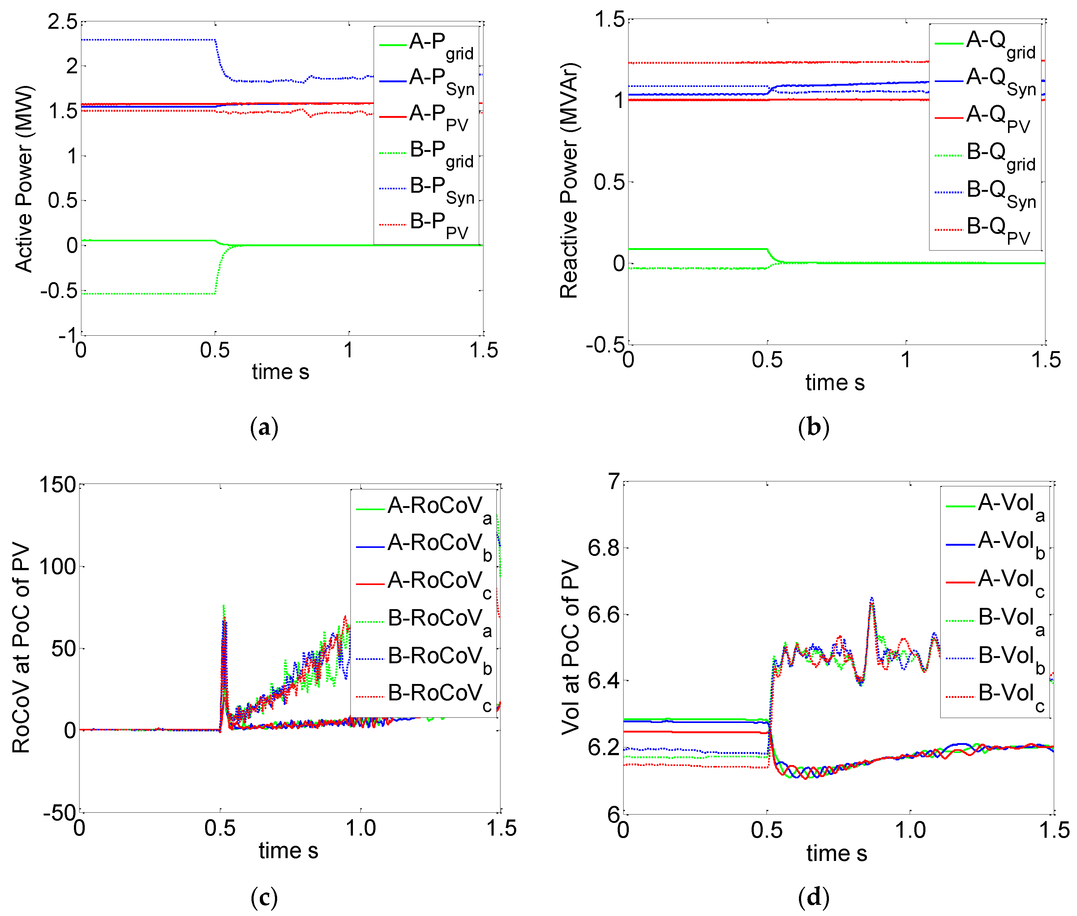
Figure 7.
Islanding detection signal for case 1, scenario A and B.

Figure 8.
Single phase to ground fault case study (a) Active power generation of DGs and grid for case 2, scenario A and B; (b) Reactive power outputs of DGs and grid for case 2, scenario A and B; (c) Rate of change of voltages at the PoC, scenario A and B; (d) Symmetrical component of the voltage at the PoC, scenario A; (e) Symmetrical component of the voltage at the PoC, scenario B.

Figure 9.
Fault detection signal for scenario A and B.

Figure 10.
Three-phase to ground fault case study (a) Active power generation of DGs and grid for case 3, scenario A and B; (b) Reactive power outputs of DGs and grid for case 3, scenario A and B; (c) Rate of change of voltages at the PoC, scenario A and B; (d) Symmetrical component of the voltage at the PoC, scenario A; (e) Symmetrical component of the voltage at the PoC, scenario B.
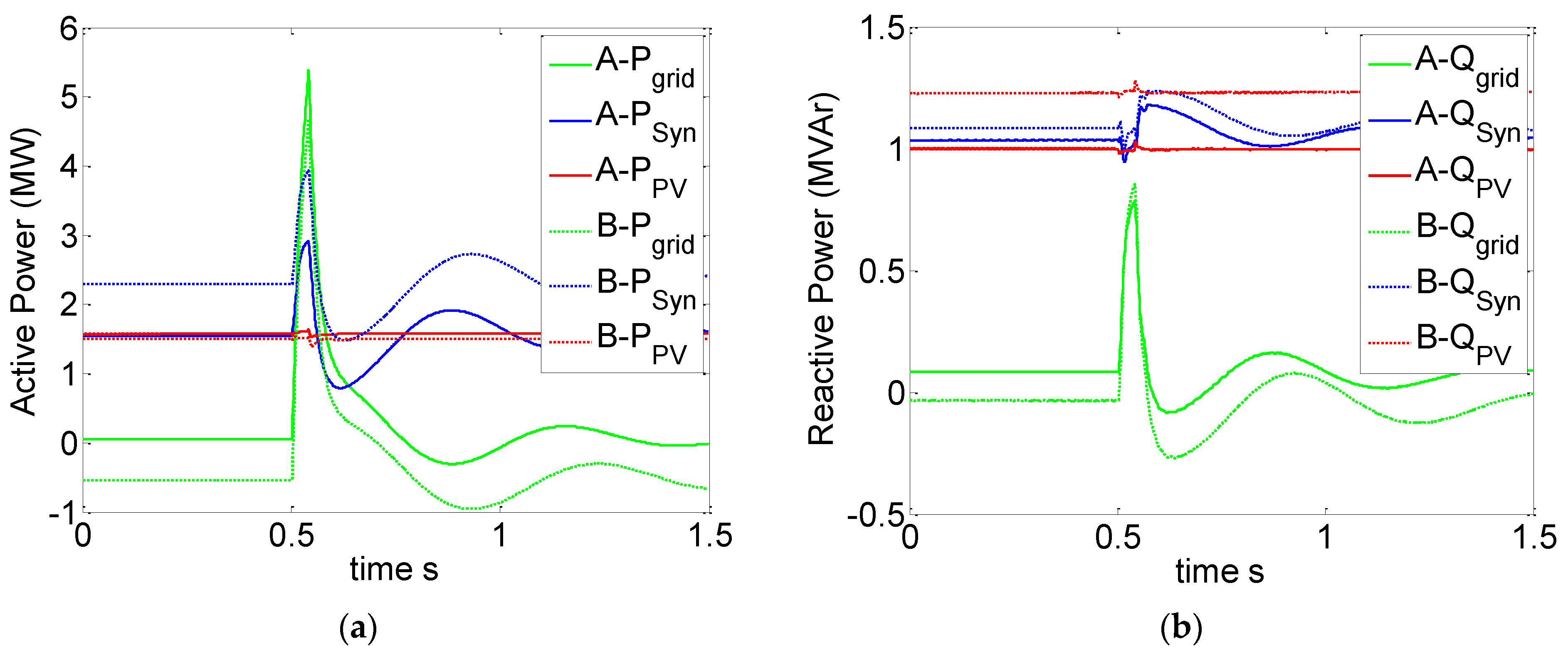
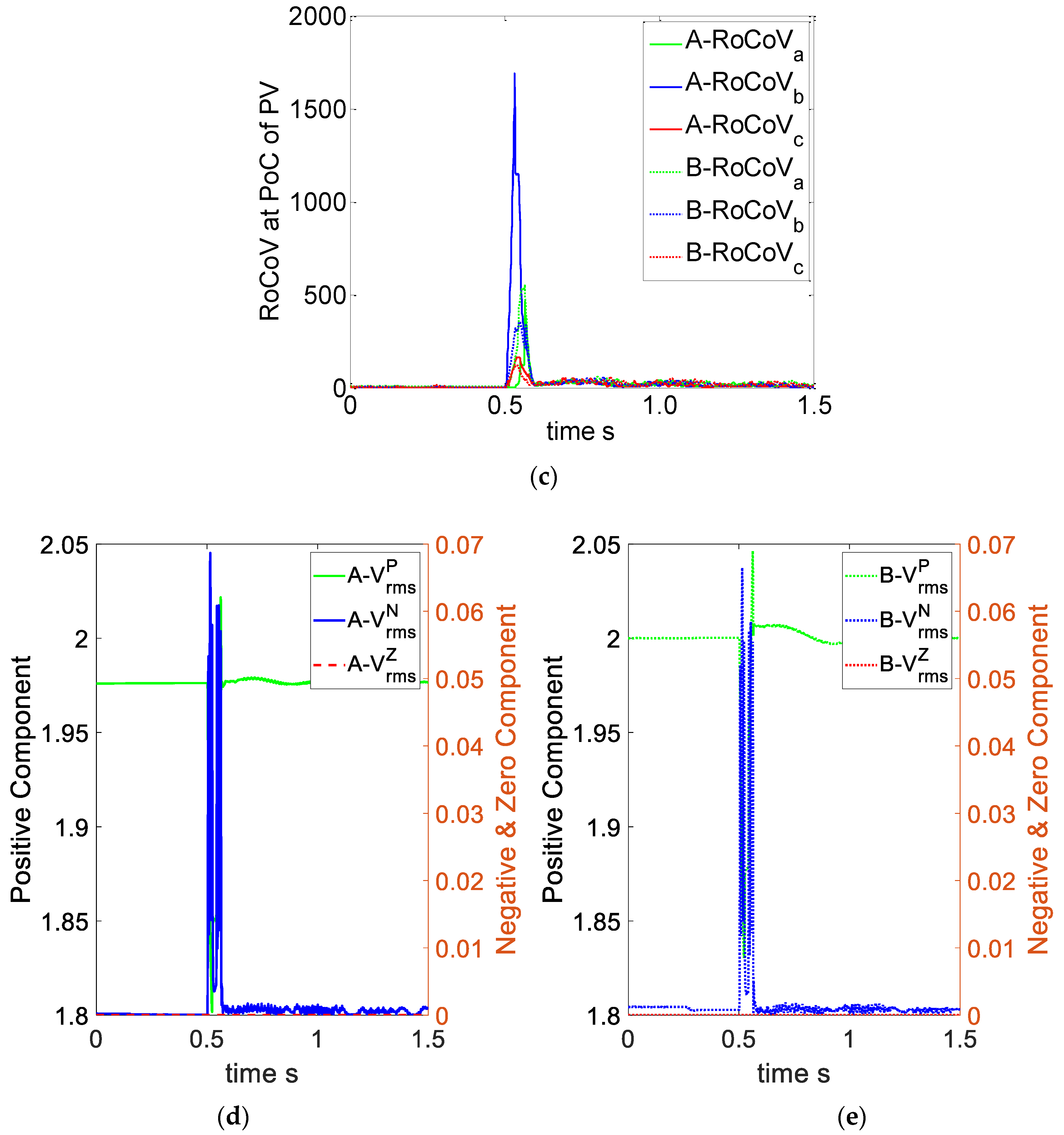
Figure 11.
Fault detection signal for case 3, scenarios A and B.

Figure 12.
Load increment in MG (a) Active power generation of DGs and grid, scenario A and B; (b) Reactive power generation of DGs and grid, scenario A and B; (c) Rate of change of the voltages at the PoC of PV, scenario A and B; (d) The VoI index at the PoC of PV, scenario A and B.
Figure 12.
Load increment in MG (a) Active power generation of DGs and grid, scenario A and B; (b) Reactive power generation of DGs and grid, scenario A and B; (c) Rate of change of the voltages at the PoC of PV, scenario A and B; (d) The VoI index at the PoC of PV, scenario A and B.
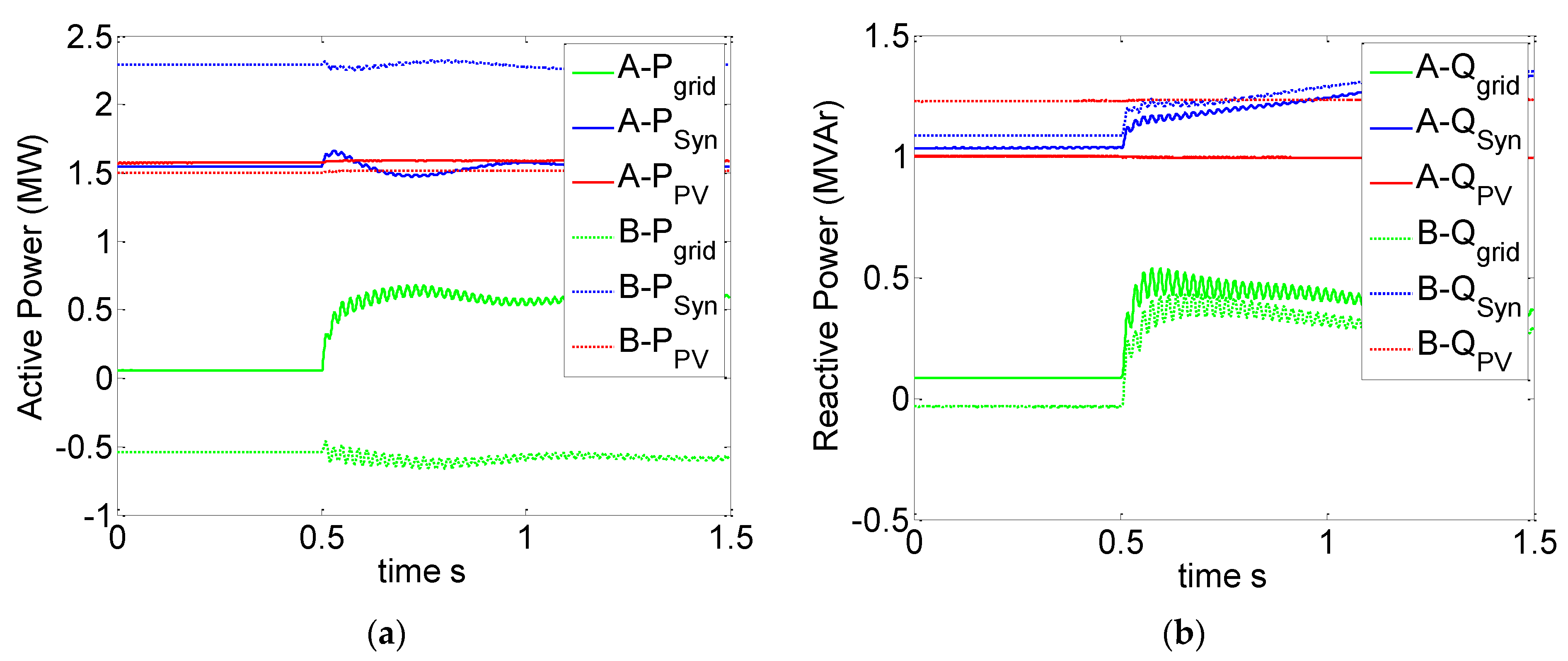
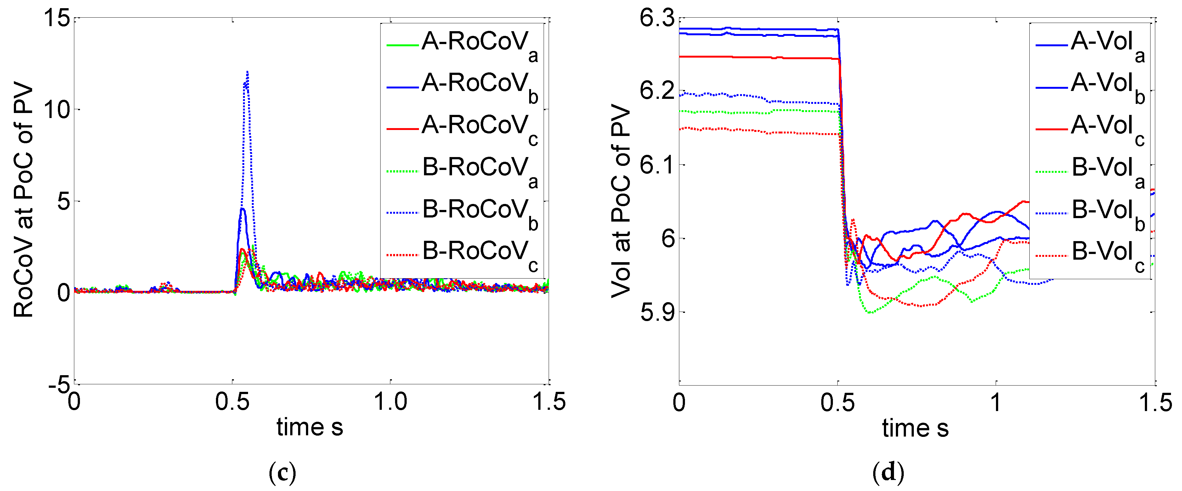
Figure 13.
Islanding and fault detection signal for case 4.

Figure 14.
Capacitor Switching in MG (a) Reactive power generation of DGs and grid, scenario A and B; (b) Rate of change of the voltages at the PoC of PV, scenario A and B; (c) The VoI index at the PoC of PV, scenario A and B for case 5.
Figure 14.
Capacitor Switching in MG (a) Reactive power generation of DGs and grid, scenario A and B; (b) Rate of change of the voltages at the PoC of PV, scenario A and B; (c) The VoI index at the PoC of PV, scenario A and B for case 5.

Figure 15.
Boolean signal of islanding and fault detection for case 5.

Figure 16.
Non-detection zone (NDZ) of the proposed islanding detection technique.


Table 1.
Different proposed scenarios.
| Case Studies | Description |
|---|---|
| Case 1 | Islanding event |
| Case 2 | Single phase to ground fault |
| Case 3 | Three-phase to ground fault |
| Case 4 | Sudden connection of load |
| Case 5 | Capacitor switching |
Publisher’s Note: MDPI stays neutral with regard to jurisdictional claims in published maps and institutional affiliations. |
© 2020 by the authors. Licensee MDPI, Basel, Switzerland. This article is an open access article distributed under the terms and conditions of the Creative Commons Attribution (CC BY) license (http://creativecommons.org/licenses/by/4.0/).
Share and Cite
MDPI and ACS Style
Karimi, M.; Farshad, M.; Hong, Q.; Laaksonen, H.; Kauhaniemi, K. An Islanding Detection Technique for Inverter-Based Distributed Generation in Microgrids. Energies 2021, 14, 130. https://doi.org/10.3390/en14010130
AMA Style
Karimi M, Farshad M, Hong Q, Laaksonen H, Kauhaniemi K. An Islanding Detection Technique for Inverter-Based Distributed Generation in Microgrids. Energies. 2021; 14(1):130. https://doi.org/10.3390/en14010130
Chicago/Turabian StyleKarimi, Mazaher, Mohammad Farshad, Qiteng Hong, Hannu Laaksonen, and Kimmo Kauhaniemi. 2021. "An Islanding Detection Technique for Inverter-Based Distributed Generation in Microgrids" Energies 14, no. 1: 130. https://doi.org/10.3390/en14010130
Note that from the first issue of 2016, this journal uses article numbers instead of page numbers. See further details here.