
Application and Suitability of Polymeric Materials as Insulators in Electrical Equipment

 , ,
, ,  ,
,  ,
,  , ,
, ,  and
and
Abstract
:
1. Introduction
2. Polymers
2.1. Types of Polymers
2.1.1. Thermoplastic Polymers
2.1.2. Thermoset Polymers
2.1.3. Elastomers
2.2. Preparation and Characterization of Polymeric Materials
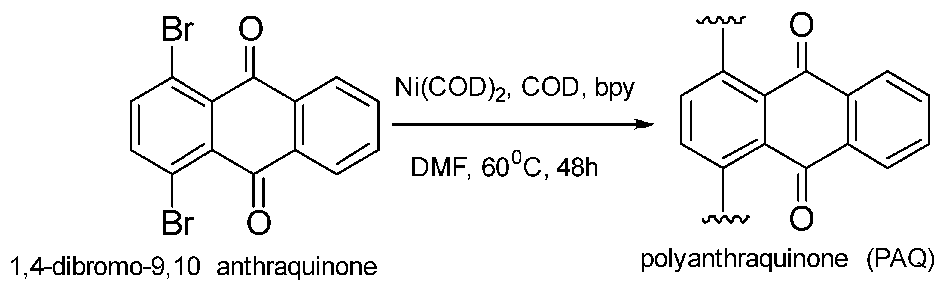
2.2.1. Poly(9,10-phenanthrenequinone) for HV Electrode
2.2.2. Thermoplastic High Performance for Cable Insulation System
Polyethylene Materials
Polypropylene Materials
- Solution blending;
- Melt blending;
- Extrusion.
Carbon Nanotube–Polyurethane Nanocomposite
2.2.3. Epoxy Resin of 9,9′-bis-(3,5-dibromo-4-hydroxyphenyl)anthrone-10 and Jute Composite
3. Properties of Polymers
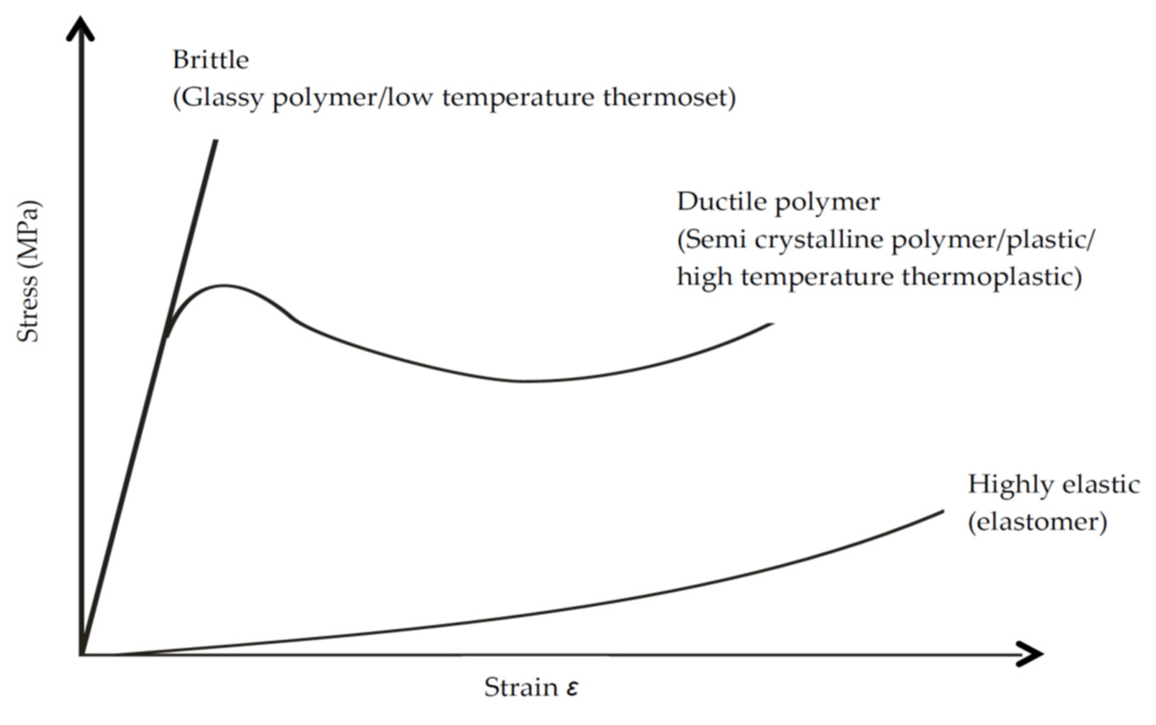
3.1. Mechanical
3.1.1. Impact Behavior
3.1.2. Tensile Test
3.1.3. Bending Test
3.2. Thermal
3.2.1. Mold Stress-Relief Distortion
3.2.2. Generic Thermal Indices
3.2.3. Relative Thermal Capability
3.2.4. Relative Thermal Index
3.2.5. Temperature Excursions beyond the Maximum Temperature
3.3. Electrical
3.3.1. Dielectric Strength
- Environmental exposure: Certain ecological conditions such as severe exposure to chemicals, radiation, ozone, and oxidation weaken or break the chemical bond of polymers [93]. Most polymers fail prematurely due to moisture that creates conducting path within their layers, leading to treeing [96]. Performing an approach on polymers together with the presence of contaminants fast-tracks the breakdown process.
- Electrode effects: It is a fact that the electrode properties may influence the breakdown strength of polymers depending on temperature [97]. Different electrode materials, sizes, and geometries [92] can also affect polymers’ breakdown strength. The area of the electrodes is inversely proportional to the dielectric strength [97].
- Temperature: One significant factor that affects the dielectric strength of polymers is temperature. However, for polymers subjected to high temperatures, there is the likelihood of oxidation and corona coupled with severe degradation and tracking of the material [93].
- Voltage application: The rate of voltage change on polymers can also affect their dielectric strength. Fast application of voltage encourages electrical conduction, while slower voltage application promotes unavoidable degradation due to local heating, causing lower dielectric strength [93].
- Frequency: The frequency of the applied voltage is another factor that influences the dielectric strength of polymers. The heat created in any dielectric is related to the applied frequency [93].
- Specimen width: The thickness of a polymeric material is inversely proportional to its dielectric strength [96]. Increasing thickness of dielectric material creates a weaker path that may go a long way in causing breakdown [93]. Defects such as a cavity, metallic components, or contaminants within any polymer material provide an avenue for electrical discharges such as partial discharge or corona that may lead to severe degradation of the specimen and lower dielectric strength [96].
3.3.2. Dielectric Constant and Dissipation Factor
3.3.3. Volume or Surface Resistivity
4. Assessment of Polymeric Insulations for HV Applications
4.1. Partial Discharges
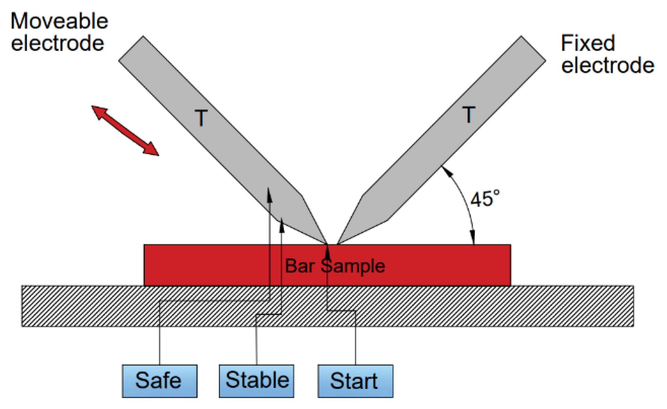
4.2. High-Current Arc Resistance to Ignition (HAI)
- Output current
- Start arc delay
- Stable position delay
- Safe position delay
- Stop arc delay
- Start position delay
- Start position
- Stable position
- Safe position.
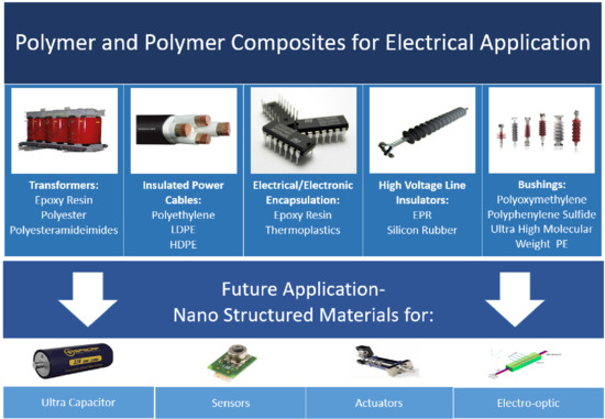
5. Applications
5.1. Transformer Insulation
5.2. Insulated Power Cables
5.3. Electrical Encapsulation Materials
5.4. Electrical and Electronic Plastics
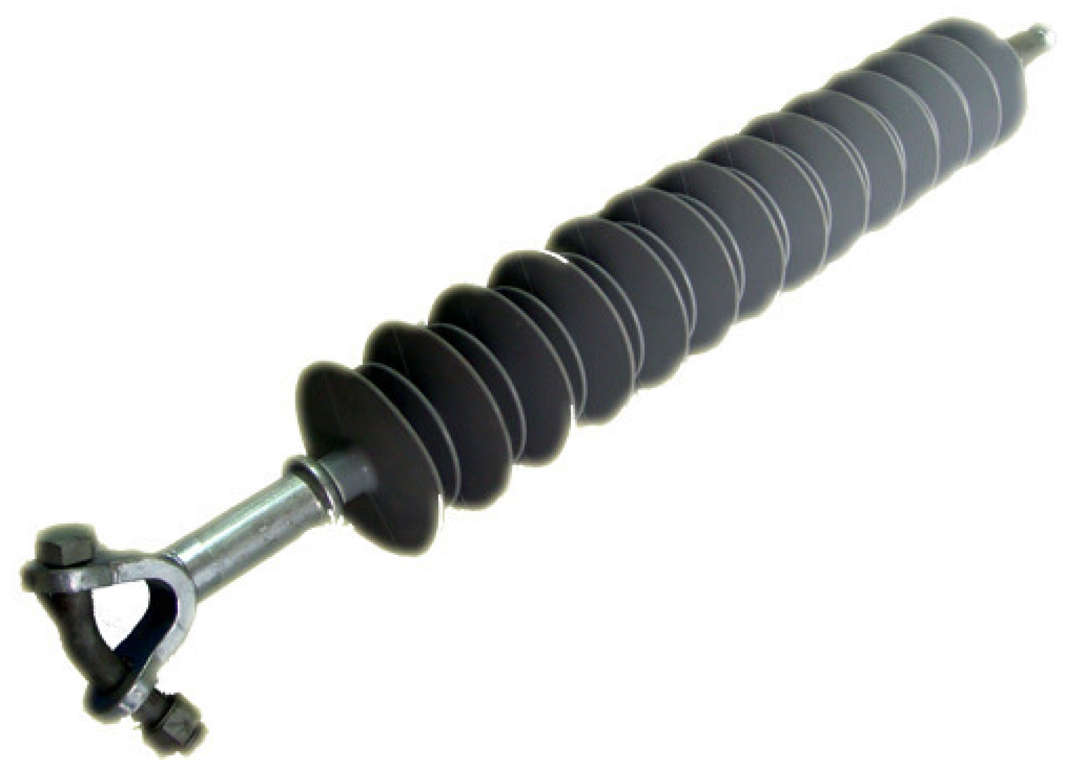
5.5. High Voltage Transmission Line Insulators
6. Challenges and Future Directions
7. Conclusions
Author Contributions
Funding
Institutional Review Board Statement
Informed Consent Statement
Data Availability Statement
Conflicts of Interest
References
- Alfalahi, A.H.M. Study of factors affecting the dielectric strength of [EP/ZrO2-y2O3] Nanocomposites. J. Eng. Appl. Sci. 2018, 13, 484–488. [Google Scholar]
- Nasreen, S.; Treich, G.M.; Baczkowski, M.L.; Mannodi-Kanakkithodi, A.K.; Cao, Y.; Ramprasad, R.; Sotzing, G. Polymer Dielectrics for Capacitor Application. In Kirk-Othmer Encyclopedia of Chemical Technology; John Wiley & Sons, Inc.: Hoboken, NJ, USA, 2017; pp. 1–29. [Google Scholar]
- Müller, K.; Bugnicourt, E.; Latorre, M.; Jorda, M.; Echegoyen Sanz, Y.; Lagaron, J.; Miesbauer, O.; Bianchin, A.; Hankin, S.; Bölz, U.; et al. Review on the processing and properties of polymer nanocomposites and nanocoatings and their applications in the packaging, automotive and solar energy fields. Nanomaterials 2017, 7, 74. [Google Scholar] [CrossRef] [Green Version]
- Bur, A.J. Dielectric properties of polymers at microwave frequencies: A review. Polymer 1985, 26, 963–977. [Google Scholar] [CrossRef]
- Rimdusit, S.; Ishida, H. Development of new class of electronic packaging materials based on ternary systems of benzoxazine, epoxy, and phenolic resins. Polymer 2000, 41, 7941–7949. [Google Scholar] [CrossRef]
- Pleşa, I.; Noţingher, P.; Schlögl, S.; Sumereder, C.; Muhr, M.; Pleşa, I.; Noţingher, P.V.; Schlögl, S.; Sumereder, C.; Muhr, M. Properties of polymer composites used in high-voltage applications. Polymers 2016, 8, 173. [Google Scholar] [CrossRef]
- Tanaka, T.; Montanari, G.C.; Mulhaupt, R. Polymer nanocomposites as dielectrics and electrical insulation-perspectives for processing technologies, material characterization and future applications. IEEE Trans. Dielectr. Electr. Insul. 2004, 11, 763–784. [Google Scholar] [CrossRef]
- Madi, A.; He, Y.; Jiang, L.; Yan, B. Surface tracking on polymeric insulators used in electrical transmission lines. Indones. J. Electr. Eng. Comput. Sci. 2016, 3, 639. [Google Scholar] [CrossRef] [Green Version]
- Lalankere, G. Opportunities and challenges of employing composite materials in switchgear industry. In Proceedings of the 20th International Conference on Electricity Distribution (CIRED), Prague, Czech Republic, 8–11 June 2009; p. 644. [Google Scholar]
- Britton, L.G. Avoiding Static Ignition Hazards in Chemical Operations; John Wiley & Sons, Inc.: Hoboken, NJ, USA, 1999; ISBN 9780470935408. [Google Scholar]
- Stone, G.C.; Boulter, E.A.; Culbert, I.; Dhirani, H. Historical Development of Insulation Materials and Systems. In Electrical Insulation for Rotating Machines; Kartalopoulos, S., Ed.; John Wiley & Sons, Inc.: Hoboken, NJ, USA, 2004; pp. 73–94. [Google Scholar]
- Wohlleben, W.; Meier, M.W.; Vogel, S.; Landsiedel, R.; Cox, G.; Hirth, S.; Tomović, Ž. Elastic CNT–polyurethane nanocomposite: Synthesis, performance and assessment of fragments released during use. Nanoscale 2013, 5, 369–380. [Google Scholar] [CrossRef] [Green Version]
- Camargo, P.H.C.; Satyanarayana, K.G.; Wypych, F. Nanocomposites: Synthesis, structure, properties and new application opportunities. Mater. Res. 2009, 12, 1–39. [Google Scholar] [CrossRef] [Green Version]
- Han, Z.; Garrett, R. Overview of Polymer Nanocomposites as dielectrics and electrical insulation materials for large high voltage rotating machines. NSTI-Nanotech 2008, 2, 727–732. [Google Scholar]
- Keith Nelson, J. Overview of nanodielectrics: Insulating materials of the future. In Proceedings of the 2007 Electrical Insulation Conference and Electrical Manufacturing Expo, Nashville, TN, USA, 22–24 October 2007; pp. 229–235. [Google Scholar]
- Matthews, F.L.; Rawlings, R.D. Composite Materials: Engineering and Science, 1st ed.; CRC Press: Cambridge, UK, 1999; ISBN 1855734737. [Google Scholar]
- Sheer, M.L. Advanced composites: The leading edge in high performance motor and transformer insulation. In Proceedings of the 20th Electrical Electronics Insulation Conference, Boston, MA, USA, 7–10 October 1991; pp. 181–185. [Google Scholar]
- Tanaka, T.; Imai, T. Advances in nanodielectric materials over the past 50 years. IEEE Electr. Insul. Mag. 2013, 29, 10–23. [Google Scholar] [CrossRef]
- Rajendran Royan, N.R.; Sulong, A.B.; Sahari, J.; Suherman, H. Effect of Acid- and Ultraviolet/Ozonolysis-Treated MWCNTs on the electrical and mechanical properties of epoxy nanocomposites as bipolar plate applications. J. Nanomater. 2013, 2013, 717459. [Google Scholar] [CrossRef] [Green Version]
- Druffel, T.; Geng, K.; Grulke, E. Mechanical comparison of a polymer nanocomposite to a ceramic thin-film anti-reflective filter. Nanotechnology 2006, 17, 3584–3590. [Google Scholar] [CrossRef]
- Seena, V.; Fernandes, A.; Pant, P.; Mukherji, S.; Ramgopal Rao, V. Polymer nanocomposite nanomechanical cantilever sensors: Material characterization, device development and application in explosive vapour detection. Nanotechnology 2011, 22, 295501. [Google Scholar] [CrossRef]
- Petrović, Z.S.; Cho, Y.J.; Javni, I.; Magonov, S.; Yerina, N.; Schaefer, D.W.; Ilavský, J.; Waddon, A. Effect of silica nanoparticles on morphology of segmented polyurethanes. Polymer 2004, 45, 4285–4295. [Google Scholar] [CrossRef]
- Qian, Y.; Lindsay, C.I.; Macosko, C.; Stein, A. Synthesis and properties of vermiculite-reinforced polyurethane nanocomposites. ACS Appl. Mater. Interfaces 2011, 3, 3709–3717. [Google Scholar] [CrossRef] [PubMed]
- Sánchez-Adsuar, M.S.; Linares-Solano, A.; Cazorla-Amorós, D.; Ibarra-Rueda, L. Influence of the nature and the content of carbon fiber on properties of thermoplastic polyurethane-carbon fiber composites. J. Appl. Polym. Sci. 2003, 90, 2676–2683. [Google Scholar] [CrossRef]
- Koerner, H.; Price, G.; Pearce, N.A.; Alexander, M.; Vaia, R.A. Remotely actuated polymer nanocomposites—Stress-recovery of carbon-nanotube-filled thermoplastic elastomers. Nat. Mater. 2004, 3, 115–120. [Google Scholar] [CrossRef]
- Kim, H.; Miura, Y.; Macosko, C.W. Graphene/Polyurethane nanocomposites for improved gas barrier and electrical conductivity. Chem. Mater. 2010, 22, 3441–3450. [Google Scholar] [CrossRef]
- Khan, U.; May, P.; O’Neill, A.; Vilatela, J.J.; Windle, A.H.; Coleman, J.N. Tuning the mechanical properties of composites from elastomeric to rigid thermoplastic by controlled addition of carbon nanotubes. Small 2011, 7, 1579–1586. [Google Scholar] [CrossRef]
- Zhang, R.; Dowden, A.; Deng, H.; Baxendale, M.; Peijs, T. Conductive network formation in the melt of carbon nanotube/thermoplastic polyurethane composite. Compos. Sci. Technol. 2009, 69, 1499–1504. [Google Scholar] [CrossRef]
- Potschke, P.; Haussler, L.; Pegel, S.; Steinberger, R.; Scholz, G. Thermoplastic polyurethane filled with carbon nanotubes for electrical dissipative and conductive application. KGK Kautschuk Gummi Kunststoffe 2007, 60, 432–437. [Google Scholar]
- De Girolamo Del Mauro, A.; Grimaldi, A.I.; La Ferrara, V.; Massera, E.; Miglietta, M.L.; Polichetti, T.; Di Francia, G. A simple optical model for the swelling evaluation in polymer nanocomposites. J. Sens. 2009, 2009, 703206. [Google Scholar] [CrossRef] [Green Version]
- Chen, W.; Tao, X. Self-organizing alignment of carbon nanotubes in thermoplastic polyurethane. Macromol. Rapid Commun. 2005, 26, 1763–1767. [Google Scholar] [CrossRef]
- Koerner, H.; Liu, W.; Alexander, M.; Mirau, P.; Dowty, H.; Vaia, R.A. Deformation–morphology correlations in electrically conductive carbon nanotube—thermoplastic polyurethane nanocomposites. Polymer 2005, 46, 4405–4420. [Google Scholar] [CrossRef]
- BASF. Polyurethanes Elastollan Material Properties. Available online: http://www.polyurethanes.basf.de/pu/Elastollan/Elastollan_Materialeigenschaften (accessed on 7 March 2019).
- Zhang, L.; Zhu, J.; Zhou, W.; Wang, J.; Wang, Y. Thermal and electrical conductivity enhancement of graphite nanoplatelets on form-stable polyethylene glycol/polymethyl methacrylate composite phase change materials. Energy 2012, 39, 294–302. [Google Scholar] [CrossRef]
- Cong, H.; Radosz, M.; Towler, B.F.; Shen, Y. Polymer–inorganic nanocomposite membranes for gas separation. Sep. Purif. Technol. 2007, 55, 281–291. [Google Scholar] [CrossRef]
- Wang, T.-L.; Yang, C.-H.; Shieh, Y.-T.; Yeh, A.-C.; Juan, L.-W.; Zeng, H.C. Synthesis of new nanocrystal-polymer nanocomposite as the electron acceptor in polymer bulk heterojunction solar cells. Eur. Polym. J. 2010, 46, 634–642. [Google Scholar] [CrossRef]
- Ruiyi, L.; Qianfang, X.; Zaijun, L.; Xiulan, S.; Junkang, L. Electrochemical immunosensor for ultrasensitive detection of microcystin-LR based on graphene–gold nanocomposite/functional conducting polymer/gold nanoparticle/ionic liquid composite film with electrodeposition. Biosens. Bioelectron. 2013, 44, 235–240. [Google Scholar] [CrossRef]
- Kaur, J.; Lee, J.H.; Shofner, M.L. Influence of polymer matrix crystallinity on nanocomposite morphology and properties. Polymer 2011, 52, 4337–4344. [Google Scholar] [CrossRef]
- Kutvonen, A.; Rossi, G.; Ala-Nissila, T. Correlations between mechanical, structural, and dynamical properties of polymer nanocomposites. Phys. Rev. E 2012, 85, 41803. [Google Scholar] [CrossRef] [Green Version]
- Kutvonen, A.; Rossi, G.; Puisto, S.R.; Rostedt, N.K.J.; Ala-Nissila, T. Influence of nanoparticle size, loading, and shape on the mechanical properties of polymer nanocomposites. J. Chem. Phys. 2012, 137, 214901. [Google Scholar] [CrossRef] [Green Version]
- Ducháček, V. Recent developments for thermoplastic elastomers. J. Macromol. Sci. Part B 1998, 37, 275–282. [Google Scholar] [CrossRef]
- Grigore, M.; Grigore, E.M. Methods of recycling, properties and applications of recycled thermoplastic polymers. Recycling 2017, 2, 24. [Google Scholar] [CrossRef] [Green Version]
- Habib Mnaathr, S.; Saher, H.; Al-Hseenawy, N. The influences of thermoplastic polymers on the electrical efficiency if used as material insulation in cables. Chem. Mater. Eng. 2014, 2, 169–172. [Google Scholar] [CrossRef]
- Ashby, M.F.; Shercliff, H.; Cebon, D. Materials: Engineering, Science, Processing and Design, 1st ed.; Elsevier Butterworth-Heinemann: Oxford, UK, 2007; ISBN 0750683910. [Google Scholar]
- Hanna, D.; Goodman, S.H. Handbook of Thermoset Plastics, 3rd ed.; Elsevier Science: Amsterdam, The Netherlands, 2013; ISBN 9781455731091. [Google Scholar]
- Ismail, N.H.; Mustapha, M. A review of thermoplastic elastomeric nanocomposites for high voltage insulation applications. Polym. Eng. Sci. 2018, 58, E36–E63. [Google Scholar] [CrossRef]
- Ellingford, C.; Wemyss, A.M.; Zhang, R.; Prokes, I.; Pickford, T.; Bowen, C.; Coveney, V.A.; Wan, C. Understanding the enhancement and temperature-dependency of the self-healing and electromechanical properties of dielectric elastomers containing mixed pendant polar groups. J. Mater. Chem. C 2020, 8, 5426–5436. [Google Scholar] [CrossRef]
- Wemyss, A.M.; Ellingford, C.; Morishita, Y.; Bowen, C.; Wan, C. Dynamic polymer networks: A new avenue towards sustainable and advanced soft machines. Angew. Chem. 2021. [Google Scholar] [CrossRef]
- Adeosun, S.O.; Lawal, G.I.; Balogun, S.A.; Akpan, E.I. Review of green polymer nanocomposites. J. Miner. Mater. Charact. Eng. 2012, 11, 385–416. [Google Scholar] [CrossRef]
- Thomas, S.; Stephen, R.; Thomas, S.; Bandyopadhyay, S. Polymer nanocomposites: Preparation, properties and applications. Rubber Fibers Plast. Int. 2007, 1, 49–56. [Google Scholar]
- Gacitúa, W.E.; Ballerini, A.A.; Zhang, J. Polymer nanocomposites: Synthetic and natural fillers a review. Maderas Cienca Y Tecnol. 2005, 7, 159–178. [Google Scholar] [CrossRef] [Green Version]
- Fu, S.; Sun, Z.; Huang, P.; Li, Y.; Hu, N. Some basic aspects of polymer nanocomposites: A critical review. Nano Mater. Sci. 2019, 1, 2–30. [Google Scholar] [CrossRef]
- Vo, T.H.; Shekhirev, M.; Kunkel, D.A.; Orange, F.; Guinel, M.J.-F.; Enders, A.; Sinitskii, A. Bottom-up solution synthesis of narrow nitrogen-doped graphene nanoribbons. Chem. Commun. 2014, 50, 4172–4174. [Google Scholar] [CrossRef] [PubMed] [Green Version]
- Xianying, D.; Meilin, W.; Bencai, D.; Shujing, L.; Yuli, Z.; Xiangjun, Z.; Libing, G. 2,7-Dibromo-9-Hydroxyl Phenanthrene Derivatives and Preparation Method Thereof. China Patent CN102775279B, 5 March 2014. [Google Scholar]
- Långvik, O.; Sandberg, T.; Wärnå, J.; Murzin, D.Y.; Leino, R. One-pot synthesis of (R)-2-acetoxy-1-indanone from 1,2-indanedione combining metal catalyzed hydrogenation and chemoenzymatic dynamic kinetic resolution. Catal. Sci. Technol. 2015, 5, 150–160. [Google Scholar] [CrossRef]
- Yamamoto, T.; Etori, H. Poly(anthraquinone)s Having a .pi.-Conjugation System along the Main Chain. Synthesis by organometallic polycondensation, redox behavior, and optical properties. Macromolecules 1995, 28, 3371–3379. [Google Scholar] [CrossRef]
- Marcano, D.C.; Kosynkin, D.V.; Berlin, J.M.; Sinitskii, A.; Sun, Z.; Slesarev, A.; Alemany, L.B.; Lu, W.; Tour, J.M. Improved synthesis of graphene oxide. ACS Nano 2010, 4, 4806–4814. [Google Scholar] [CrossRef] [PubMed]
- Pirnat, K.; Bitenc, J.; Vizintin, A.; Krajnc, A.; Tchernychova, E. Indirect synthesis route toward cross-coupled polymers for high voltage organic positive electrodes. Chem. Mater. 2018, 30, 5726–5732. [Google Scholar] [CrossRef]
- Ahmed Dabbak, S.; Illias, H.; Ang, B.; Abdul Latiff, N.; Makmud, M. Electrical properties of polyethylene/polypropylene compounds for high-voltage insulation. Energies 2018, 11, 1448. [Google Scholar] [CrossRef] [Green Version]
- Hosier, I.L.; Vaughan, A.S.; Swingler, S.G. Structure–property relationships in polyethylene blends: The effect of morphology on electrical breakdown strength. J. Mater. Sci. 1997, 32, 4523–4531. [Google Scholar] [CrossRef]
- Green, C.D.; Vaughan, A.S.; Stevens, G.C.; Sutton, S.J.; Geussens, T.; Fairhurst, M.J. Recyclable power cable comprising a blend of slow-crystallized polyethylenes. IEEE Trans. Dielectr. Electr. Insul. 2013, 20, 1–9. [Google Scholar] [CrossRef]
- Rishina, L.A.; Kissin, Y.V.; Lalayan, S.S.; Krasheninnikov, V.G. Synthesis of atactic polypropylene: Propylene polymerization reactions with TiCl4–Al(C2H5)2Cl/Mg(C4H9)2 catalyst. J. Appl. Polym. Sci. 2019, 136, 47692. [Google Scholar] [CrossRef]
- De Rosa, C.; Auriemma, F. Structure and physical properties of syndiotactic polypropylene: A highly crystalline thermoplastic elastomer. Prog. Polym. Sci. 2006, 31, 145–237. [Google Scholar] [CrossRef]
- Green, C.; Vaughan, A.; Stevens, G.; Pye, A.; Sutton, S.; Geussens, T.; Fairhurst, M. Thermoplastic cable insulation comprising a blend of isotactic polypropylene and a propylene-ethylene copolymer. IEEE Trans. Dielectr. Electr. Insul. 2015, 22, 639–648. [Google Scholar] [CrossRef] [Green Version]
- Wohlleben, W.; Brill, S.; Meier, M.W.; Mertler, M.; Cox, G.; Hirth, S.; von Vacano, B.; Strauss, V.; Treumann, S.; Wiench, K.; et al. On the lifecycle of nanocomposites: Comparing released fragments and their in-vivo hazards from three release mechanisms and four nanocomposites. Small 2011, 7, 2384–2395. [Google Scholar] [CrossRef] [PubMed]
- Nguyen, T.; Pellegrin, B.; Bernard, C.; Gu, X.; Gorham, J.M.; Stutzman, P.; Stanley, D.; Shapiro, A.; Byrd, E.; Hettenhouser, R.; et al. Fate of nanoparticles during life cycle of polymer nanocomposites. J. Phys. Conf. Ser. 2011, 304, 12060. [Google Scholar] [CrossRef] [Green Version]
- Mansfield, E.; Kar, A.; Hooker, S.A. Applications of TGA in quality control of SWCNTs. Anal. Bioanal. Chem. 2010, 396, 1071–1077. [Google Scholar] [CrossRef]
- Thanki, J.D.; Parsania, P.H. Physico-chemical study of modified mannich base cured epoxy resin of 9,9’-bis(4-Hydroxy Phenyl) Anthrone-10 and its jute and glass composites. J. Polym. Mater. 2016, 33, 101–109. [Google Scholar]
- Thanki, J.D.; Patel, J.P.; Parsania, P.H. Synthesis and characterization of epoxy resin of 9,9′-bis-(3,5-dibromo-4-hydroxyphenyl) anthrone-10 and its jute composite. Des. Monomers Polym. 2018, 21, 9–17. [Google Scholar] [CrossRef] [Green Version]
- Su, W.-F. Principles of Polymer Design and Synthesis; Lecture Notes in Chemistry; Springer: Berlin/Heidelberg, Germany, 2013; Volume 82, ISBN 978-3-642-38729-6. [Google Scholar]
- Balani, K.; Verma, V.; Agarwal, A.; Narayan, R. Physical, Thermal, and Mechanical Properties of Polymers. In Biosurfaces; Balani, K., Verma, V., Agarwal, A., Narayan, R., Eds.; John Wiley & Sons, Inc.: Hoboken, NJ, USA, 2015; pp. 329–344. [Google Scholar]
- Schadler, L.S. Polymer-Based and Polymer-Filled Nanocomposites. In Nanocomposite Science and Technology; Ajayan, P.M., Schadler, L.S., Braun, P.V., Eds.; Wiley-VCH Verlag GmbH & Co. KGaA: Weinheim, Germany, 2004; pp. 77–153. [Google Scholar]
- Lach, R.; Antonova Gyurova, L.; Grellmann, W. Application of indentation fracture mechanics approach for determination of fracture toughness of brittle polymer systems. Polym. Test. 2007, 26, 51–59. [Google Scholar] [CrossRef]
- Mohamad, N.; Muchtar, A.; Ghazali, M.J.; Mohd, D.; Azhari, C.H. The effect of filler on epoxidised natural rubber-alumina nanoparticles composites. Eur. J. Sci. Res. 2008, 24, 538–547. [Google Scholar]
- Kimura, K. Multistress aging of machine insulation systems. In Proceedings of the 1995 Conference on Electrical Insulation and Dielectric Phenomena, Virginia Beach, VA, USA, 22–25 October 1995; pp. 205–210. [Google Scholar]
- Crompton, T.R. Polymer Reference Book; Smithers Rapra Technology Ltd.: Shewsbury, Shropshire, UK, 2006; ISBN 1859574920. [Google Scholar]
- Grellmann, W.; Seidler, S. Polymer Testing; Hanser Publications: München, Germany, 2013; ISBN 9781569905494. [Google Scholar]
- Bonten, C. Kunststofftechnik Einführung und Grundlagen, 1st ed.; Carl Hanser Verlag: München, Germany, 2014; ISBN 3446440933. [Google Scholar]
- Lim, K.S.; Mariatti, M.; Kamarol, M.; Ghani, A.B.A.; Shafi Halim, H.; Abu Bakar, A. Properties of nanofillers/crosslinked polyethylene composites for cable insulation. J. Vinyl Addit. Technol. 2019, 25, E147–E154. [Google Scholar] [CrossRef] [Green Version]
- Hedir, A.; Bechouche, A.; Moudoud, M.; Teguar, M.; Lamrous, O.; Rondot, S. Experimental and predicted XLPE cable insulation properties under UV radiation. Turkish J. Electr. Eng. Comput. Sci. 2020, 28, 1763–1775. [Google Scholar] [CrossRef]
- Yasmin, A.; Daniel, I.M. Mechanical and thermal properties of graphite platelet/epoxy composites. Polymer 2004, 45, 8211–8219. [Google Scholar] [CrossRef]
- Yang, H.S.; Kim, H.J.; Son, J.; Park, H.J.; Lee, B.J.; Hwang, T.S. Rice-husk flour filled polypropylene composites; mechanical and morphological study. Compos. Struct. 2004, 63, 305–312. [Google Scholar] [CrossRef]
- Ray, D.; Bhattacharya, D.; Mohanty, A.K.; Drzal, L.T.; Misra, M. Static and Dynamic Mechanical Properties of Vinylester Resin Matrix Composites Filled with Fly Ash. Macromol. Mater. Eng. 2006, 291, 784–792. [Google Scholar] [CrossRef]
- Mehdipour-Ataei, S.; Tabatabaei-Yazdi, Z. Heat Resistant Polymers. In Encyclopedia of Polymer Science and Technology; John Wiley & Sons, Inc.: Hoboken, NJ, USA, 2015; pp. 1–31. [Google Scholar]
- Guevara-Morales, A.; Figueroa-López, U. Residual stresses in injection molded products. J. Mater. Sci. 2014, 49, 4399–4415. [Google Scholar] [CrossRef]
- Pak, S.Y.; Kim, S.Y.; Kim, S.H.; Youn, J.R. Measurement of residual stresses in polymeric parts by indentation method. Polym. Test. 2013, 32, 946–952. [Google Scholar] [CrossRef]
- UL Standard for Polymeric Materials. In Long Term Property Evaluations (UL—746B); Underwriters’ Laboratories: Chicago, IL, USA, 2018.
- IEC Electrical Insulating Materials. In Thermal Endurance Properties—Part 1: Ageing Procedures and Evaluation of Test Results (IEC 60216-1:2013); International Electrotechnical Commission: Geneva, Switzerland, 2013; pp. 1–66.
- PBI. Advanced Materials Co. Ltd. Heat Resistance. Available online: http://www.pbi-am.com/en/properties/heat-resistance (accessed on 8 March 2019).
- Chen, H.; Ginzburg, V.V.; Yang, J.; Yang, Y.; Liu, W.; Huang, Y.; Du, L.; Chen, B. Thermal conductivity of polymer-based composites: Fundamentals and applications. Prog. Polym. Sci. 2016, 59, 41–85. [Google Scholar] [CrossRef]
- Ngo, I.-L.; Jeon, S.; Byon, C. Thermal conductivity of transparent and flexible polymers containing fillers: A literature review. Int. J. Heat Mass Transf. 2016, 98, 219–226. [Google Scholar] [CrossRef]
- UL Standard for Polymeric Materials. In Use in Electrical Equipment Evaluations (UL—746C); Underwriters’ Laboratories: Chicago, IL, USA, 2018.
- Jafri, S.Z. Experimental Investigation of Dielectric Strength of Polymer Films; Department of Electrical and Computer Engineering, University of Windsor: Windsor, ON, Canada, 2001. [Google Scholar]
- Polymer Science Dielectric Strength of Polymers. Available online: https://polymerdatabase.com/polymer%20physics/Dielectric%20Strength.html (accessed on 14 July 2020).
- Tan, D.Q. The search for enhanced dielectric strength of polymer-based dielectrics: A focused review on polymer nanocomposites. J. Appl. Polym. Sci. 2020, 137, 49379. [Google Scholar] [CrossRef]
- Dissado, L.A.; Fothergill, J.C. Electrical Degradation and Breakdown in Polymers; Stevens, G.C., Ed.; IET: London, UK, 1992; ISBN 0863411967. [Google Scholar]
- Hikita, M.; Nagao, M.; Sawa, G.; Ieda, M. Dielectric breakdown and electrical conduction of poly(vinylidene-fluoride) in high temperature region. J. Phys. D Appl. Phys. 1980, 13, 661–666. [Google Scholar] [CrossRef]
- Jansen, J.A. Characterization of Plastics in Failure Analysis. In Failure Analysis and Prevention; ASM International: Novelty, OH, USA, 2018; pp. 437–459. [Google Scholar]
- ASTM D257–14 Standard Test Methods for DC Resistance or Conductance of Insulating Materials. In Annual B. ASTM Standard; ASTM International: Pennsylvania, PA, USA, 2014.
- Illias, H.A.; Tunio, M.A.; Bakar, A.H.A.; Mokhlis, H.; Chen, G. Partial discharge phenomena within an artificial void in cable insulation geometry: Experimental validation and simulation. IEEE Trans. Dielectr. Electr. Insul. 2016, 23, 451–459. [Google Scholar] [CrossRef]
- Kreuger, F.H. Partial Discharge Detection in High-Voltage Equipment; Butterworths-Heinemann Ltd.: Oxford, UK, 1989; ISBN 9780408020633. [Google Scholar]
- Bartnikas, R. Partial discharges. Their mechanism, detection and measurement. IEEE Trans. Dielectr. Electr. Insul. 2002, 9, 763–808. [Google Scholar] [CrossRef]
- Benzerouk, D. Pulse Sequence Analysis and Pulse Shape Analysis: Methods to Analyze Partial Discharge Processes; University of Siegen: Siegen, Germany, 2008. [Google Scholar]
- Chen, G.; Mokhlis, H.; Abu Bakar, A.H.; Illias, H.A.; Tunio, M.A. Partial discharge behaviours within a void-dielectric system under square waveform applied voltage stress. IET Sci. Meas. Technol. 2014, 8, 81–88. [Google Scholar]
- Edin, H. Partial Discharges Studied with Variable Frequency of the Applied Voltage. Ph.D Thesis, Department of Electrical Engineering, KTH Royal Institute of Technology, Stockhom, Sweeden, 2001. [Google Scholar]
- Kozako, M.; Fuse, N.; Ohki, Y.; Okamoto, T.; Tanaka, T. Surface degradation of polyamide nanocomposites caused by partial discharges using IEC (b) electrodes. IEEE Trans. Dielectr. Electr. Insul. 2004, 11, 833–839. [Google Scholar] [CrossRef]
- Henk, P.O.; Kortsen, T.W.; Kvarts, T.; Saeidi, A. Increasing the PDendurance of epoxy and XLPE insulation by nanoparticle silica dispersion in the polymer. In Proceedings of the Nordic Insulation Symposium 2001, Stockholm, Sweeden, 11–13 June 2001. [Google Scholar]
- Middendorf, W. Successful Performance of the High Current Arc Ignition Test. IEEE Trans. Electr. Insul. 1982, EI-17, 429–433. [Google Scholar] [CrossRef]
- Middendorf, W.H.; Kirshteyn, M. The high current arc ignition test. IEEE Electr. Insul. Mag. 1988, 4, 21–25. [Google Scholar] [CrossRef]
- UL Standard for Polymeric Materials. In Short Term Property Evaluations (UL—746A); Underwriters’ Laboratories: Chicago, IL, USA, 2012.
- Wagner, R.; Stimitz, J. Properties of Plastic Materials for Use in Automotive Applications—Study of Arc Track Properties of Plastic Materials when Subjected to DC Voltages Ranging from 12 VDC—150 VDC: Addendum Report; Underwriters’ Laboratories: Chicago, IL, USA, 2004. [Google Scholar]
- Watanabe, T.; Sato, M.; Kuwajima, H. High current DC arc ignition testing of GRP. Composites 1982, 13, 24–28. [Google Scholar] [CrossRef]
- Zuercher, J.; Hetzmannseder, E. Testing Arc Faults in Automotive 42 V Applications. In Proceedings of the 42 Volt Automotive Systems Conference, Chicago, IL, USA, 17–18 September 2001. [Google Scholar]
- Hetymannseder, E.; Zuercher, H.; Hastings, J. Method for Realistic Evaluation of Arc Faults Detection Performance. In Proceedings of the 21st International Conference on E1ectrical Contacts, Zurich, Switzerland, 9–12 September 2002; pp. 296–302. [Google Scholar]
- Hastings, J.K.; Zuercher, J.C.; Hetzmannseder, E. Electrical Arcing and Material Ignition Levels. In Proceedings of the Society for Automotive Engineering (SAE) 2004 World Congress, Detroit, MI, USA, 8–11 March 2004. [Google Scholar]
- Jiang, H.; Brazis, P.; Navarro, N. DC high-energy arcing ignition (HAI) resistance for polymeric materials: Part I: Consistency and repeatability of DC-HAI system. In Proceedings of the 2012 IEEE Symposium on Product Compliance Engineering Proceedings, Portland, OR, USA, 5–7 November 2012; pp. 1–4. [Google Scholar]
- Stone, G.C. Advancements during the past quarter century in on-line monitoring of motor and generator winding insulation. IEEE Trans. Dielectr. Electr. Insul. 2002, 9, 746–751. [Google Scholar] [CrossRef]
- North West Laboratory Insulation. Materials for Transformers Winding. Available online: http://ferrite.ru/products/electrical_tape_en/ (accessed on 8 March 2019).
- Kirby, A.J. Polyimides: Materials, Processing and Applications; RAPRA Technology Limited Shawbury: RAPRA Review Reports; Pergamon Press: Oxford, UK, 1992; ISBN 9780080419664. [Google Scholar]
- Moore, G.F. Electric Cables Handbook, 3rd ed.; Blackwell Science: Oxford, UK, 1997; ISBN 9780632040759. [Google Scholar]
- Souza, R.E.; Gomes, R.M.; Lima, G.S.; Silveira, F.H.; De Conti, A.; Visacro, S. Analysis of the impulse breakdown behavior of covered cables used in compact distribution lines. Electr. Power Syst. Res. 2018, 159, 24–30. [Google Scholar] [CrossRef]
- Hanley, T.L.; Burford, R.P.; Fleming, R.J.; Barber, K.W. A general review of polymeric insulation for use in HVDC cables. IEEE Electr. Insul. Mag. 2003, 19, 13–24. [Google Scholar] [CrossRef]
- Tanaka, T. Dielectric nanocomposites with insulating properties. IEEE Trans. Dielectr. Electr. Insul. 2005, 12, 914–928. [Google Scholar] [CrossRef]
- Abdel-Gawad, N.M.K.; El Dein, A.Z.; Mansour, D.-E.A.; Ahmed, H.M.; Darwish, M.M.F.; Lehtonen, M. Multiple enhancement of PVC cable insulation using functionalized SiO2 nanoparticles based nanocomposites. Electr. Power Syst. Res. 2018, 163, 612–625. [Google Scholar] [CrossRef]
- Singha, S.; Thomas, M. Dielectric properties of epoxy nanocomposites. IEEE Trans. Dielectr. Electr. Insul. 2008, 15, 12–23. [Google Scholar] [CrossRef]
- Kumara, S.; Xu, X.; Hammarström, T.; Ouyang, Y.; Pourrahimi, A.M.; Müller, C.; Serdyuk, Y.V. Electrical characterization of a new crosslinked copolymer blend for DC cable insulation. Energies 2020, 13, 1434. [Google Scholar] [CrossRef] [Green Version]
- Wichmann, M.W.; Boyer, T.D.; Keller, C.T. Coil encapsulation with thermoplastic resins. In Proceedings of the Electrical Insulation Conference and Electrical Manufacturing and Coil Winding Conference, Rosemont, IL, USA, 25 September 1997; pp. 525–528. [Google Scholar]
- Melick, D.; Browning, D.; Shelton, K. Evaluation of electrical material properties: Embedment stress testing on electrical encapsulation resins. In Proceedings of the Electrical/Electronics Insulation Conference, Chicago, IL, USA, 4–7 October 1993; pp. 639–641. [Google Scholar]
- Vanga-Bouanga, C.; Savoie, S.; Frechette, M.F.; David, E. Modification of polyethylene properties by encapsulation of inorganic material. IEEE Trans. Dielectr. Electr. Insul. 2014, 21, 1–4. [Google Scholar] [CrossRef]
- Locatelli, M.-L.; Khazaka, R.; Diaham, S.; Pham, C.-D.; Bechara, M.; Dinculescu, S.; Bidan, P. Evaluation of encapsulation materials for high-temperature power device packaging. IEEE Trans. Power Electron. 2014, 29, 2281–2288. [Google Scholar] [CrossRef]
- Imperiale, I.; Reggiani, S.; Pavarese, G.; Gnani, E.; Gnudi, A.; Baccarani, G.; Ahn, W.; Alam, M.A.; Varghese, D.; Hernandez-Luna, A.; et al. Role of the Insulating fillers in the encapsulation material on the lateral charge spreading in HV-ICs. IEEE Trans. Electron. Devices 2017, 64, 1209–1216. [Google Scholar] [CrossRef]
- George, J.; Compagno, T.; Rodgers, K.; Waldron, F.; Barrett, J. Reliability of plastic-encapsulated electronic components in supersaturated steam environments. IEEE Trans. Components, Packag. Manuf. Technol. 2015, 5, 1423–1431. [Google Scholar] [CrossRef]
- Imai, T.; Sawa, F.; Nakano, T.; Ozaki, T.; Shimizu, T.; Kozako, M.; Tanaka, T. Effects of nano- and micro-filler mixture on electrical insulation properties of epoxy based composites. IEEE Trans. Dielectr. Electr. Insul. 2006, 13, 319–326. [Google Scholar] [CrossRef]
- Castellon, J.; Nguyen, H.; Agnel, S.; Toureille, A.; Frechette, M.; Savoie, S.; Krivda, A.; Schmidt, L.E. Electrical properties analysis of micro and nano composite epoxy resin materials. IEEE Trans. Dielectr. Electr. Insul. 2011, 18, 651–658. [Google Scholar] [CrossRef]
- Choudhury, M.; Mohanty, S.; Nayak, S.K.; Aphale, R. Preparation and characterization of electrically and thermally conductive polymeric nanocomposites. J. Miner. Mater. Charact. Eng. 2012, 11, 744–756. [Google Scholar] [CrossRef]
- van der Pol, J.A.; Rongen, R.T.H.; Bruggers, H.J. Model and design rules for eliminating surface potential induced failures in high voltage integrated circuits. Microelectron. Reliab. 2000, 40, 1267–1272. [Google Scholar] [CrossRef]
- Cornigli, D.; Reggiani, S.; Gnudi, A.; Gnani, E.; Baccarani, G.; Fabiani, D.; Varghese, D.; Tuncer, E.; Krishnan, S.; Nguyen, L. Characterization of dielectric properties and conductivity in encapsulation materials with high insulating filler contents. IEEE Trans. Dielectr. Electr. Insul. 2018, 25, 2421–2428. [Google Scholar] [CrossRef]
- Nationwide Plastics. Plastics for Electrical Insulation. Available online: https://www.nationwideplastics.net/industries/electrical-insulation/ (accessed on 7 March 2019).
- Vose, F.C.; Nichols, F.S. A polymer insulator for high-voltage transmission lines. Electr. Eng. 1963, 82, 684–688. [Google Scholar] [CrossRef]
- Pigini, A. Polymeric Materials for HV Insulators. Available online: https://www.inmr.com/polymeric-materials-insulators/ (accessed on 12 April 2021).
- Al-Gheilani, A.; Rowe, W.; Li, Y.; Wong, K.L. Stress Control Methods on a High Voltage Insulator: A Review. In Energy Procedia; Elsevier: Amsterdam, The Netherlands, 2017; Volume 110, pp. 95–100. [Google Scholar]
- Qasim, S.A.; Gupta, N. Functionally graded material composites for effective stress control in insulators. In Proceedings of the IEEE International Conference on Properties and Applications of Dielectric Materials; Institute of Electrical and Electronics Engineers Inc.: Sydney, Australia, 2015; pp. 232–235. [Google Scholar]
- Wang, F.; Zhang, P.; Gao, M.; Zhao, X.; Gao, J. Research on the non-linear conductivity characteristics of nano-Sic silicone rubber composites. In Proceedings of the Annual Report—Conference on Electrical Insulation and Dielectric Phenomena (CEIDP), Chenzhen, China, 20–23 October 2013; pp. 535–538. [Google Scholar]
- Li, S.; Yu, S.; Feng, Y. Progress in and prospects for electrical insulating materials. High Volt. 2016, 1, 122–129. [Google Scholar] [CrossRef]


| Materials | Dielectric Constant, έ (rt) |
|---|---|
| Isotactic polypropylene | 2.28 |
| Atactic polypropylene | 2.16 |
| Polyphenylene sulfide | 3.5 |
| Polyethylene terephthalate | 3.3 |
| Polycarbonate | 3.0 |
| Polyimide | 2.78–3.48 |
| Polyurea | 5.18–6.19 |
| Polyurethanes | 3.84–6.09 |
| Polyvinylidene fluoride | 4.09–10.5 |
| Material | Application |
|---|---|
| Polyethylene | Cable and wire insulation |
| Polypropylene | Kettles |
| Polyvinyl chloride | Cable and wire insulation, cable trucking |
| Polystyrene | Refrigerator trays/linings, TV cabinets |
| Polycarbonate | Telephones |
| Acrylonitrile butadiene styrene | Telephone handsets, keyboards, monitors, computer cases |
| Polyamide | Food processor bearings and adaptors |
| Ethylene-vinyl acetate | Freezer door strips, lean vacuum hoses, handle-grips |
| Polyesters | Business machine parts, coffee machines, toasters |
| Polyphenylene oxide | Coffee machines, TV housings |
| Material | Application |
|---|---|
| Alkyd resins | Circuit breakers, switchgear |
| Amino resins | Lighting fixtures |
| Epoxy resins | Electrical components |
| Phenol formaldehyde | Fuse boxes, knobs, switches, handles |
| Urea-formaldehyde | Fuse boxes, knobs, switches |
| Polymer | Conductivity (W/m.k) |
| Epoxy resin | 0.19 |
| Polysulfone | 0.22 |
| Low-density polyethylene | 0.3 |
| High-density polyethylene | 0.44 |
| Polyethylene | 0.11 |
| Polycarbonate | 0.2 |
| Polystyrene | 0.14 |
| Polyimide, thermoplastic | 0.11 |
| polyphenylsulfone | 0.35 |
| Polyvinyl chloride | 0.19 |
| Nylon-6 | 0.25 |
| Nylon-6.6 | 0.26 |
| polymethylmethacrylate | 0.21 |
| Polyphenylene sulfide | 0.3 |
| Poly copolymer | 0.33 |
| Poly ethylene-vinyl acetate | 0.34 |
| Compound | Dielectric Constant (1 MHz) | Dielectric Strength (kV/cm) |
|---|---|---|
| Poly(vinyl chloride) | 2.9–3.1 | 140–200 |
| Polyacrylonitrile | 4.0–4.2 | - |
| Poly(methyl methacrylate) | 2.8–2.9 | 100–300 |
| Polycarbonate | 2.8–3.0 | 150–340 |
| Poly(ethylene terephthalate) | 3.0–3.5 | 150–200 |
| Polytetrafluoroethylene (Telfon) | 2.0–2.1 | 600–700 |
| Polypropylene | 2.2–2.3 | 230–250 |
| Polyethylene | 2.2–2.3 | 200–300 |
| Silicone Oil | 2.5 | 150 |
| Fused Silica | - | 250–400 |
| Distilled Water | 80 | 65–70 |
| Air | 1.0 | 15–30 |
Publisher’s Note: MDPI stays neutral with regard to jurisdictional claims in published maps and institutional affiliations. |
© 2021 by the authors. Licensee MDPI, Basel, Switzerland. This article is an open access article distributed under the terms and conditions of the Creative Commons Attribution (CC BY) license (https://creativecommons.org/licenses/by/4.0/).
Share and Cite
Haque, S.M.; Ardila-Rey, J.A.; Umar, Y.; Mas’ud, A.A.; Muhammad-Sukki, F.; Jume, B.H.; Rahman, H.; Bani, N.A. Application and Suitability of Polymeric Materials as Insulators in Electrical Equipment. Energies 2021, 14, 2758. https://doi.org/10.3390/en14102758
Haque SM, Ardila-Rey JA, Umar Y, Mas’ud AA, Muhammad-Sukki F, Jume BH, Rahman H, Bani NA. Application and Suitability of Polymeric Materials as Insulators in Electrical Equipment. Energies. 2021; 14(10):2758. https://doi.org/10.3390/en14102758
Chicago/Turabian StyleHaque, SK Manirul, Jorge Alfredo Ardila-Rey, Yunusa Umar, Abdullahi Abubakar Mas’ud, Firdaus Muhammad-Sukki, Binta Hadi Jume, Habibur Rahman, and Nurul Aini Bani. 2021. "Application and Suitability of Polymeric Materials as Insulators in Electrical Equipment" Energies 14, no. 10: 2758. https://doi.org/10.3390/en14102758