Article

Flow and Heat Transfer Characteristics of Supercritical N-Decane in Adjacent Cooling Channels with Opposite Flow Directions

1
Science and Technology on Scramjet Laboratory, College of Aerospace Science and Engineering, National University of Defense Technology, Changsha 410073, China
2
School of Aeronautics and Astronautics, Central South University, Changsha 410073, China
*
Author to whom correspondence should be addressed.
Energies 2021, 14(4), 1071; https://doi.org/10.3390/en14041071
Submission received: 22 January 2021 / Revised: 10 February 2021 / Accepted: 11 February 2021 / Published: 18 February 2021
(This article belongs to the Section J: Thermal Management)

Abstract

:
To ensure the safety of a scramjet, an arrangement scheme of adjacent regenerative cooling channels with opposite flow directions is adopted to decrease the maximum wall temperature. Based on extended corresponding-state methods, the flow and heat transfer characteristics of supercritical n-decane in cooling channels with same and opposite flow directions under a pressure of 3 MPa are comprehensively investigated in this paper. Compared to adjacent cooling channels with same flow direction, the local maximum wall temperature in adjacent cooling channels with opposite directions is notably reduced. Moreover, the effects of the heat flux and gravity on the development of flow field are analysed. A pair of recirculation zones is found close to the bottom wall of the cooling channels along the flow direction, the scale of which greatly expands with increasing heat flux. Once the heat flux density reaches a critical value, a phenomenon of flow asymmetry occurs. In addition, the small recirculation zones induced by the buoyancy force narrow when the gravity and heat flux directions remain the same, and the gravity effect could inhibit the generation of small-scale vortices and flow asymmetry.

1. Introduction

Due to the outstanding performance, hypersonic vehicles have become an important development direction of contemporary aviation technology [1,2,3]. As the propulsion system of most hypersonic vehicles, the scramjet engine works in a harsh thermal environment. The thermal protection technique of combustor is one of the key technologies of scramjets. According to reports, the wall temperature on the gas side of a scramjet engine reaches as high as 3000 K [4]. It is difficult to rely only on passive cooling technology to meet the thermal protection requirements. Regenerative cooling via using endothermic hydrocarbon fuels has been considered to be the most effective thermal protection method [5,6,7].
Regenerative cooling channels are arranged in the combustor wall, and fuel passes through these cooling channels to absorb heat of the combustor wall before being injected into the combustor. By changing the size, shape and spacing of the cooling channels, the heat transfer efficiency can be adjusted to satisfy the cooling requirements of different locations of the combustor [8]. At present, there are many studies on fuel characteristics in regenerative cooling channels, including heat transfer [9,10,11], thermal cracking [12,13,14], pressure drop [15,16,17], and thermo-acoustic instability [18,19,20]. Since the effective reduction in the wall surface temperature and improvement of the heat transfer coefficient are the focus of thermal protection, the heat transfer characteristics of endothermic hydrocarbon fuels have received extensive attention.
Currently, detailed studies have been carried out on the heat transfer characteristics of endothermic hydrocarbon fuels. Liu et al. [21] experimentally studied the convective heat transfer characteristics of n-decane in two vertical tubes of different sizes and revealed the influence of flow acceleration, heat flux, and regenerative cavities on the heat transfer characteristics. Wang et al. [22] studied the convective heat transfer characteristics of n-decane in a horizontal tube and found two types of heat transfer deterioration (HTD) phenomena. In addition, their research showed that increasing the pressure effectively reduced and eliminated HTD. Increasing the velocity of the fluid is benefit to increase the convective heat transfer ecoefficiency [23]. The use of some ribs in the microchannel can also effectively improve heat transfer [24,25,26,27]. Ruan et al. [28] investigated the influence of the cooling channel length, inlet flow rate, heat flux and other parameters on the transient heat transfer characteristics of n-decane at 5 MPa. Li et al. [29] examined the effect of pressure on the flow and heat transfer characteristics of supercritical n-decane. In addition, researchers have summarized heat transfer correlations of n-decane in micro-channels based on a large amount of experimental data [30,31,32].
Many efforts have been made to improve the heat transfer effect and active cooling performance. Feng et al. [33] found that the average heat transfer rate of channels with dimples was 1.64 times higher than that of smooth channels. Rahim et al. [34] studied the turbulent heat transfer characteristicsa tubular heat exchanger with two twisted-tape inserts and effect of the twist ratio. Jiang et al. [35] studied the heat transfer enhancement effect of the partial filling of tubes with porous media and reported that the heat transfer in the transcritical region increased at least 3 times. Li et al. [36] proposed that the interaction between the recirculation zone formed near micro-ribs and the secondary flow greatly enhanced local convective heat transfer and its downstream area. There have also been studies on other shapes of channels, such as rectangular [37,38,39], rotating U-duct [40], and wavy channels [41,42,43,44].
However, various complex structural designs are not suitable for the design of regenerative cooling channels in scramjet engines. A straight channel with rectangular cross-section remains the simplest and most practical design for regenerative cooling channels. Although there have been studies on adjacent-layer channels [45,46,47], researches on channels with opposite flow directions are still relatively small. In this paper, the flow and heat transfer characteristics of supercritical n-decane in cooling channels with opposite flow directions are investigated through numerical simulations. In addition, the effect of the heat flux and gravity on the changing trend of the flow field along the flow direction in cooling channels with opposite flow directions is revealed in detail.

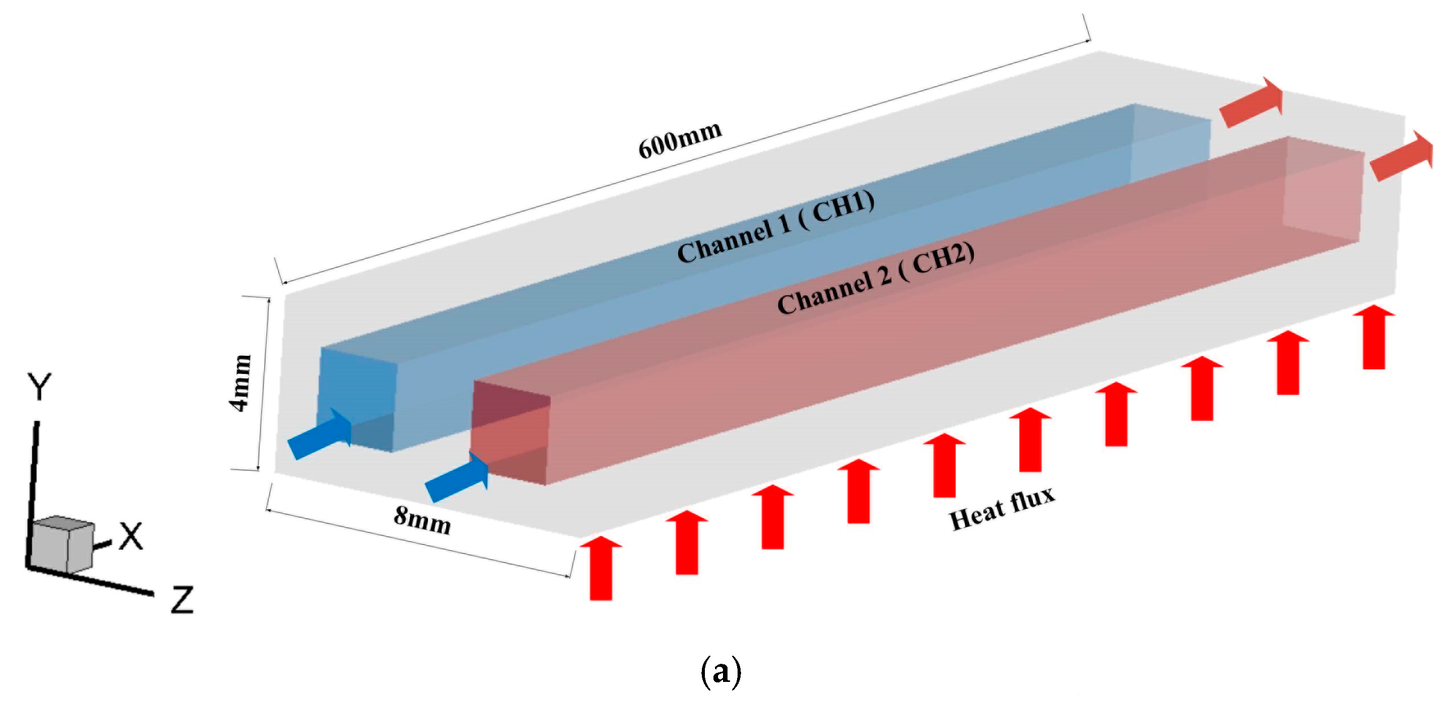
2. Computational Domain

A schematic cross-sectional view of a typical scramjet cooling channel is shown in Figure 1.
Cooling channels are arranged in the wall of the combustion chamber to absorb the generated heat during the combustion process. The cross-section of the cooling channel is generally rectangular, and the size of each cooling channel is identical. Based on periodic and symmetric conditions, previous studies have often selected only one cooling channel as the research object to reduce the calculation time. To investigate the flow and heat transfer characteristics of n-decane in cooling channels with opposite flow directions, we choose two adjacent cooling channels as the research object. The research object is consistent with numerical domain 1, as shown in Figure 1.
The research object is a cube with a width of 8 mm, a height of 4 mm, and a length of 600 mm, which contains two identical rectangular channels with a width of 2 mm, a height of 2 mm, and a length of 600 mm. The entire research object is heated only by a constant heat flux along the bottom wall. The distance between the two rectangular cooling channels is 2 mm. To ensure strict symmetry, the solid wall thickness on the top, bottom, and sides of the two rectangular channels is 1 mm. To verify the superiority of cooling channels with opposite flow directions, as shown in Figure 2, two cases are considered, namely, case A, i.e., cooling channels with the same flow direction, and case B, i.e., cooling channels with opposite flow directions.
The difference between these two cases is only reflected in the positions of the inlet and outlet. For description convenience in the following analysis, we denote these two channels as CH1 and CH2.

3. Results

3.1. Numerical Methods

Solid and fluid domains are discretized with structured grids. The cross-sectional grid of the calculation area is shown in Figure 3. To ensure that the first grid layer adjacent to the wall of the fluid domain satisfies the requirement of y + < 1 , the thickness of the first mesh layer near the wall of the fluid domain and the growth rate towards the centre area are set to 0.002 mm and 1.05, respectively. Through calculations, the range of y + n cases A and B is 0–0.47 and 0–0.51, respectively.
In case A and case B, the common boundary conditions are as follows: in the fluid area, the mass flow rate of both inlets is 1 g/s, the temperature is 300 K, each outlet is defined under outflow conditions, and the operating pressure is 3 MPa. In the solid area, the uniform heat flux on the bottom wall is set to 0.4 MW/m2, and top wall are adiabatic. To more accurately reflect the actual situation, the left and right sidewalls are not defined as adiabatic, and periodic boundary conditions are set to ensure consistency of the two sidewalls. The interface between the fluid and solid is automatically coupled.
Mass, momentum and energy conservation equations govern the flow and heat transfer characteristics of supercritical n-decane in the cooling channels. Many investigations have verified the effectiveness of the k ω shear stress transport (SST) turbulence model in studying the flow and heat transfer characteristics of supercritical fluids [47,48,49]. In this paper, the k ω SST turbulence model is also adopted. The finite volume method is applied to discretize the mass, momentum, and energy conservation equations. An adjacent-precision pressure-based steady solver is employed to obtain the flow and heat transfer characteristics under various conditions. The first-order upwind scheme is adopted to discretize the turbulent kinetic energy and specific dissipation rate, and the second-order upwind scheme is implemented to discretize the energy equations in space. The SIMPLC algorithm is chosen to realize the coupling of pressure and velocity.

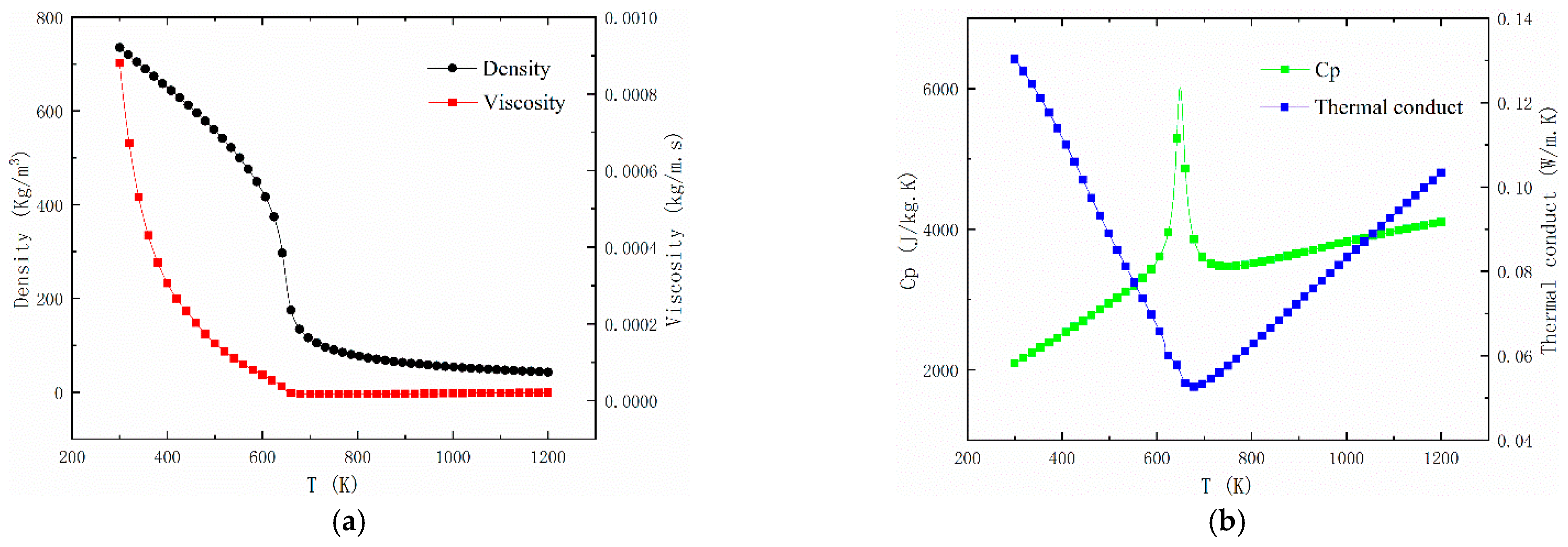
3.2. Thermophysical Properties

Determination of the thermophysical properties of n-decane is particularly important in numerical simulations. It is feasible to calculate the thermophysical properties of n-decane by the extended corresponding-states principle with SUPERTRAPP software (National Institute of Standards and Technology, Gaithersburg, the United States of America) developed by the NIST [50]. Based on this principle, thermophysical properties, such as the density, viscosity, specific heat under a constant pressure (Cp), and thermal conductivity, can be accurately calculated. Figure 4 shows the thermophysical data of n-decane at 3 MPa calculated with the software.
Stainless steel is selected as the material of the solid area, and specific parameters are derived from the literature. The density and specific heat of the material are 7930 kg/m3 and 500 J/kg·K, respectively. The linear changes in the thermal conductivity are 12.1 and 28.5 W/m·K at 290 K and 1300 K, respectively.

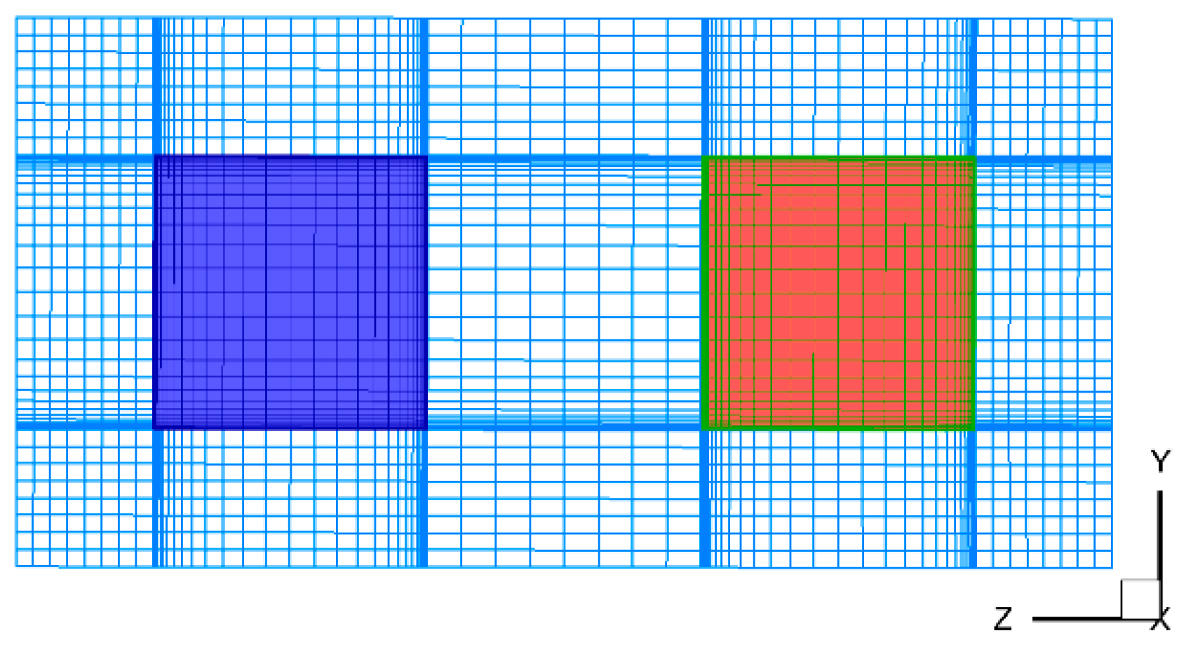
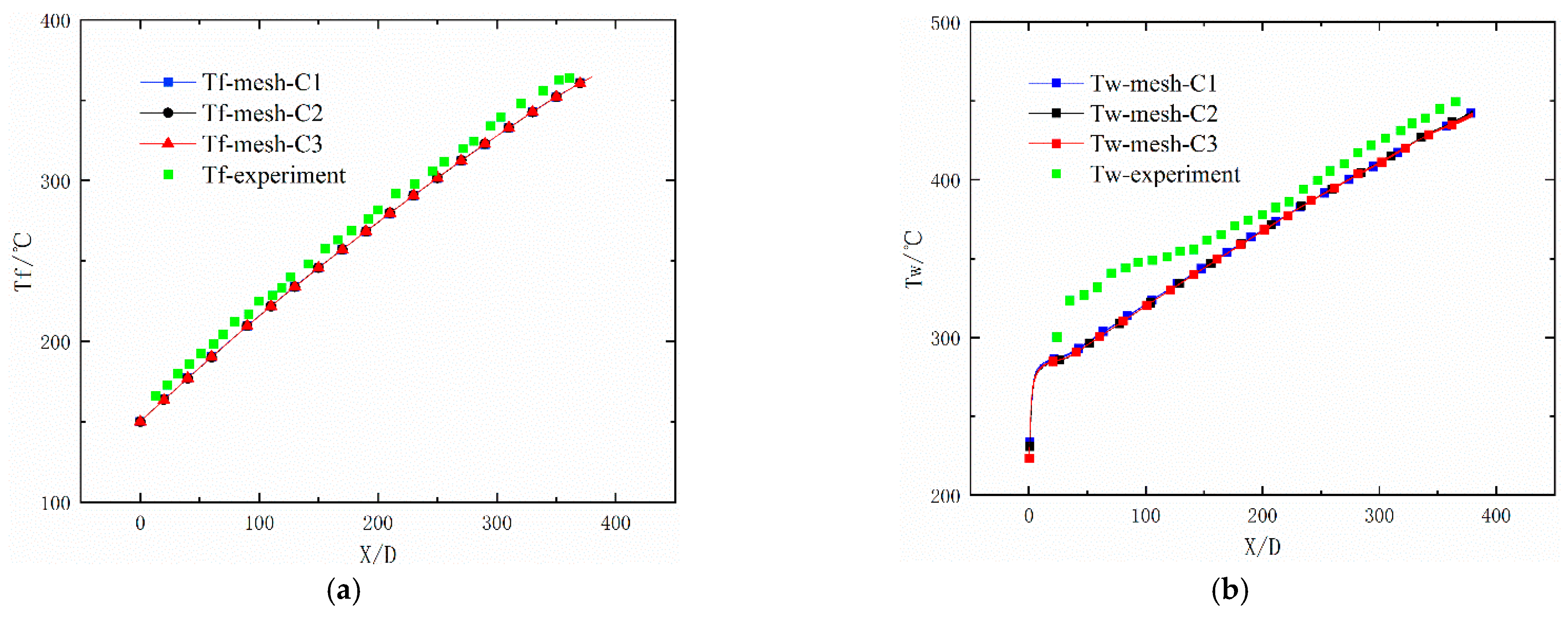
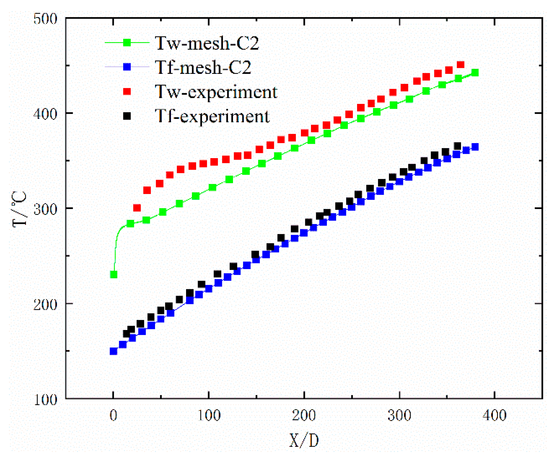
3.3. Validation of the Numerical Simulations and Mesh Sensitivity Determination

Validation of the numerical methods and mesh sensitivity determination are necessary tasks before numerical simulation research. The present study is mainly compared to the experimental study performed by Liu et al. [21]. Since the cross-section of the cooling channel considered in their experiment is circular, to ensure consistency of the comparison conditions, this article first employs a straight channel with a circular cross-section for simulation verification purposes. Selecting a cooling channel with an inner diameter of 2 mm as an example, the simulation results for three different grid numbers are compared to the experimental results. Three sets of grids were used in the verification and they are denoted as mesh-C1, mesh-C2, and mesh-C3. The common boundary conditions in the experiment are as follows: The inner diameter (Din) of the channel is 2 mm and the outer diameter (Dout) is 3 mm, the operating pressure (P) is 3 MPa, the mass flow (G) is 10 kg/h, the inlet temperature is 423.15 K, and the wall heat flux (Q) is 406 kW/m2. Figure 5 shows the variations in wall temperature and fluid temperature along the reduced axial length.
Figure 5 shows the comparison between the numerical results of the three sets of meshes and the experimental results. It can be observed that fluid temperature results obtained from the three simulations have almost no difference. In addition, the numerical results are highly consistent with the experimental results. The maximum relative errors of fluid temperature and wall temperature calculated from mesh-C1 and mesh-C2 is 0.18% and 0.22%. Further refinement of the mesh, relative errors in terms of the fluid temperature and wall temperature between mesh-C2 and mesh-C3 is less than 0.15% and 0.41%. It can be considered that the grid corresponding to mesh-C2 can be used for numerical simulation. The maximum relative error of fluid temperature calculated by mesh-C2 and the experimental result is 2.99%. The wall temperature error obtained by numerical simulation and experiment is less than 10.84%. In addition, as shown in Figure 6, we also compared the simulation results and experimental data of the downstream situation with the mesh-C2. The simulation results are closed to the experiment data. These results indicate that the simulation model and numerical method in this paper are effective and reliable, and the simulation results have a high accuracy.
In addition to verifying the effectiveness of the numerical simulation, the mesh sensitivity must be evaluated. In this work, case A is adopted to evaluate the mesh sensitivity. The mass-weighted average temperatures of outlet 1 and outlet 2 are used as evaluation parameters of the mesh sensitivity. Three sets of meshes of different densities are considered. The simulation results for these three sets of meshes are listed in Table 1.
As the mesh number is increased from 1.74 to 2.85 million, the relative errors between the average temperatures of outlets 1 and 2 are 0.027% and 0.027%, respectively. The number of grids is further increased to 4.60 million, and the relative errors corresponding to these two parameters are 0.013% and 0.013%, respectively. Comparing the simulation results for these three sets of meshes, it is observed that a mesh number of 4.60 million satisfies the accuracy requirements.

4. Results and Discussion

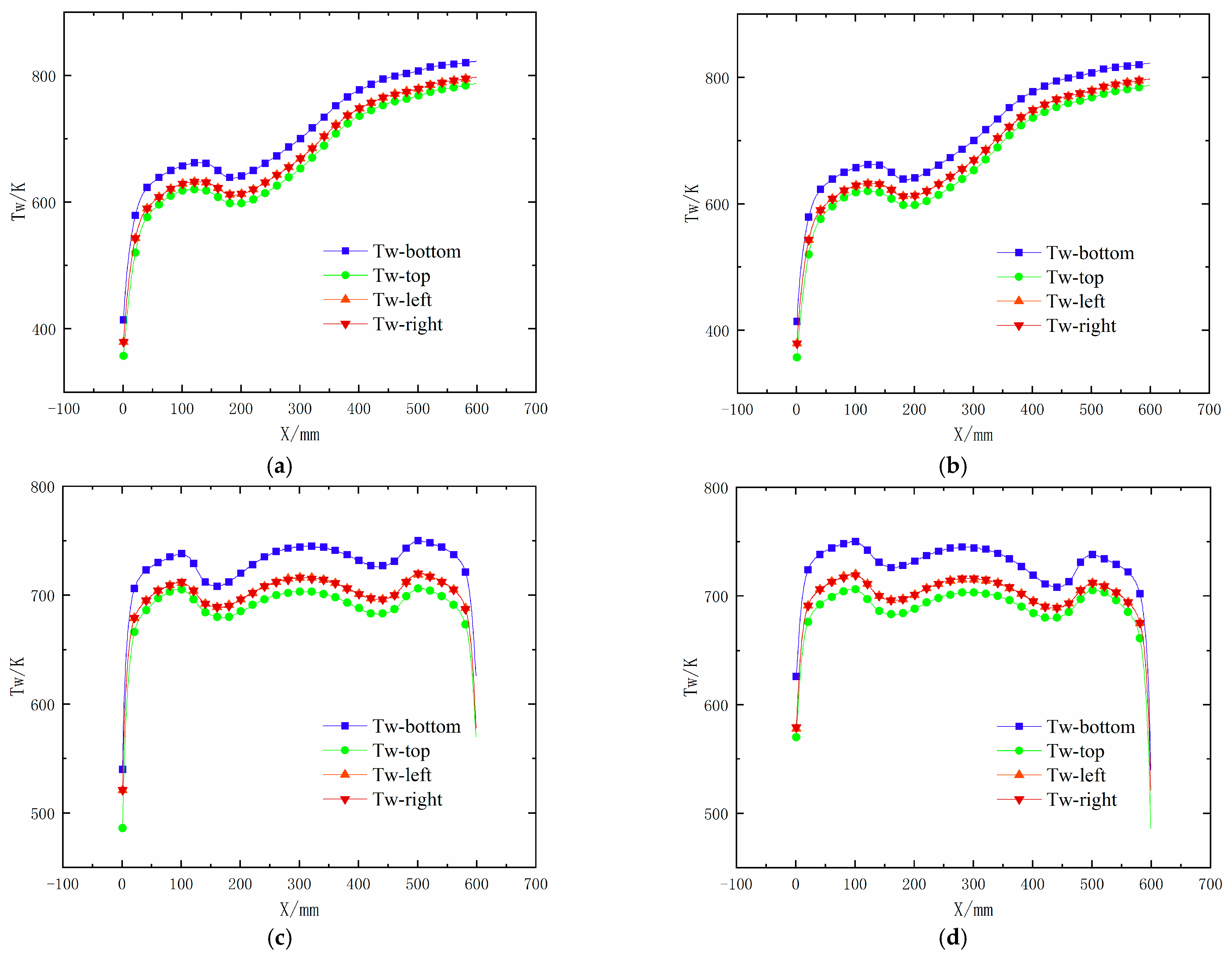
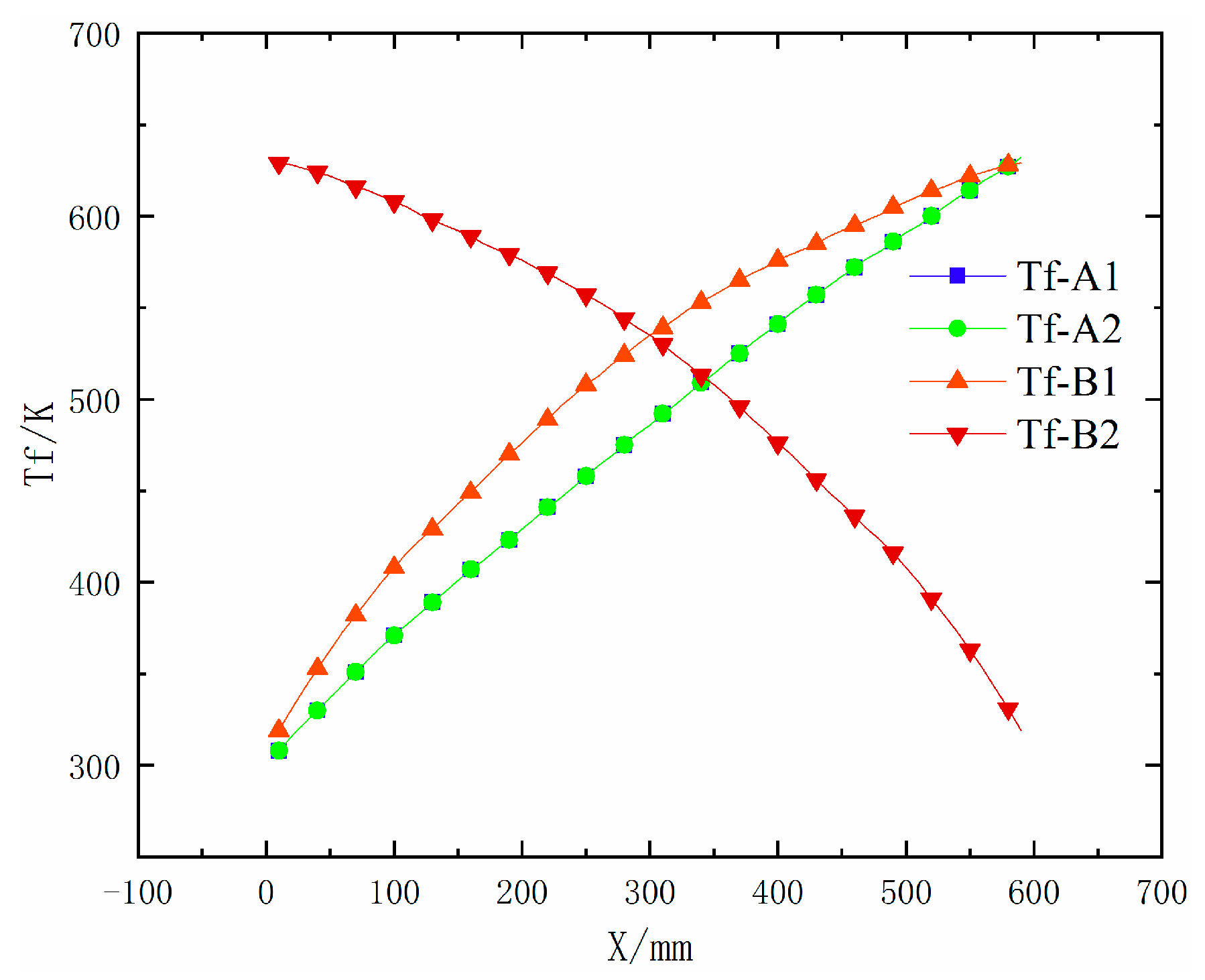
4.1. Description of the Wall and Fluid Temperatures

In this section, the wall and fluid temperatures of the regenerative cooling channels with the same and opposite directions are analysed in detail. The wall temperatures of the four sides along the X-axis are shown in Figure 7. The temperature distribution of the four sidewalls reveals the same tendency. Due to the symmetry of the cooling channels, the wall temperature distribution along the X-axis of the two channels in case A is identical. In addition, the temperatures of the left and right walls of each channel are the same. Similar symmetry results are found in case B, which proves the rationality of the computational domain and numerical method.
As shown in Figure 7a,c the temperature of the bottom wall is higher than that of the other walls at the same location along the flow direction because it is located near the heated wall of the solid domain. A clear HTD phenomenon is observed in the area of X = 60–180 mm, as shown in Figure 7a. The wall temperature in this area demonstrates a tendency of first rapidly rising and then gradually decreasing. The maximum wall temperature occurs near the outlet of the channel in case A. Compared to case A with the same flow direction, the distribution of the wall temperature exhibits a completely different trend. The wall temperature experiences three successional upward and downward trends. The HTD phenomenon is observed in the above three regions, and the heat transfer enhancement (HTE) phenomenon occurs in two regions of each channel in case B. Because the wall and fluid temperatures of the two channels are the same along their respective flow directions, only one channel is selected as the research object. Choosing channel 1 as an example, the three HTD regions are X = 50–160 mm, X = 200–400 mm, and X = 440–550 mm, and the two HTE regions are X = 120–300 mm and X = 300–480 mm. As shown in Figure 7c,d, the wall temperature near the inlet and outlet is relatively low, while the maximum wall temperature occurs at the center of the channel. In addition, the maximum wall temperature of the channels with opposite flow directions is much lower than that of the channels with the same flow direction. The maximum wall temperature in case A is 822.28 K, while it is 747.73 K in case B. The maximum wall temperature is reduced by 9.07% only by changing the flow direction. In scramjet engines, decreasing the maximum wall temperature is an important challenge, which is closely related to flight safety. Obviously, cooling channels with opposite flow directions could effectively avoid the occurrence of local high wall temperatures.
To visualize the fluid temperature distribution at different locations along the flow direction more clearly, the cross-sectional fluid temperature at intervals of 60 mm is shown in Figure 8.
It is obvious that the fluid temperature distribution also exhibits a good symmetry along the flow direction. By comparing the fluid temperatures along the flow direction, the temperature near the bottom wall is relatively low, while the temperature near the top wall is relatively high. Although the same phenomenon is found in case B, the cross-sectional temperature is relatively uniform near the outlet. These results may occur because the fluid near the outlet is close to the fluid with a relatively low temperature in the adjacent channel. Heat transfer between the fluids in the two adjacent channels through the solid region promotes a more uniform temperature distribution in the channel with a relatively high temperature. The bulk fluid temperature distribution along the X-axis is shown in Figure 9.
We only compare the temperature distribution characteristics of channel 1 in the two cases due to the symmetry of the two channels in each case. The bulk fluid temperature of channel 1 in case A uniformly increases along the flow direction, while it first quickly rises and then slowly rises in case B. It is evident that the bulk fluid temperature increases relatively slowly when it is relatively high. By evaluating the wall temperature in the region of X = 0–300 mm, it is found that the wall temperature of channel 1 in case A is slightly higher than that of channel 1 in case B. The fluid heat transfer in this region in case A is higher than that in case B, resulting in a slightly faster increase in the fluid temperature in this area. This in turn explains the results whereby the fluid temperature increases relatively slow in the region of X = 300–600 mm. It is concluded that the heat transfer capacity of n-decane in the low-temperature region is effectively improved via the application of cooling channels with opposite flow directions.

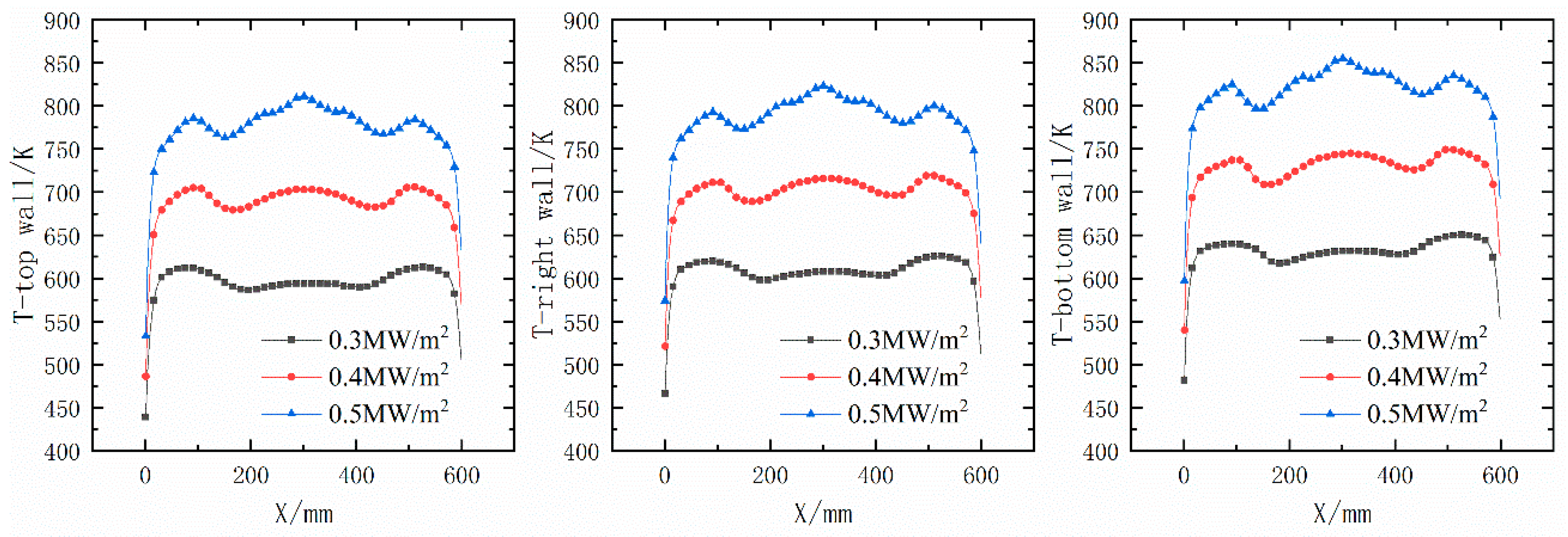
4.2. Effect of the Heat Flux

Cooling channels with opposite directions are beneficial to avoid the occurrence of local high wall temperatures, as discussed in the last section. To clarify the effect of the heat flux on the flow and heat transfer characteristics of the fuel in cooling channels with opposite directions, we also perform numerical simulations under heat fluxes of 0.3 and 0.5 MW/m2. They are named case B1 and case B2 respectively. The heat flux along the bottom wall is changed under each condition, while the other boundary conditions agree with those in case B. It can be observed that the wall temperature along the flow direction of each channel is symmetric. The temperatures of the bottom, right and top walls of channel 1 along the X-axis under the various heat fluxes are shown in Figure 10.
With increasing heat flux, the wall temperature gradually increases. The wall temperature distribution along the flow direction under the different heat fluxes remains almost consistent. The wall temperature experiences three upward and downward trends. However, there are wall temperature differences near the second peak. Specifically, the differences are within the range of X = 150–450 mm. It is obvious that the wall temperature gradient is relatively high with a relatively high heat flux. In addition, the starting position of the second peak is closer to the inlet, and the end position is closer to the outlet when increasing heat flux.
To better understand the fluid temperature distribution along the flow direction, streamlines at different cross-sectional positions are shown in Figure 11.
Channel 1 in each case is selected as the research object. According to the thermophysical properties of n-decane, as shown in Figure 4, we found that the density of n-decane decreases with increasing temperature. In addition, the temperature of the fuel near the wall is obviously higher than that near the mainstream. Because the heat flux is imposed on the bottom wall of the solid zone, the temperature of the bottom wall is slightly higher than that of the other three walls. When the fuel near the bottom wall absorbs heat, the temperature starts to rise, and the density decreases. The fuel with a relatively high temperature gradually moves upward, and the fuel with a relatively low temperature moves downward under the influence of gravity. A recirculation zone is formed through the interaction between the cold and hot fluids. As shown in Figure 11, we found that a pair of main recirculation zones occurs at the location of X = 90 mm. As the fuel temperature is further increased, two small recirculation zones are found near the bottom wall of the cooling channel, corresponding to the location of X = 120 mm. It is speculated that the formation of these two small recirculation zones occurs due to the increase in the temperature. With increasing temperature, the heated fluid along the bottom wall hardly enters the main recirculation zones quickly and remains near the wall due to the effect of the downward motion of the cold fluid. With the movement of the above two main recirculation zones, two small recirculation zones gradually form and develop to a greater extent. It is observed that these two small recirculation zones gradually expand from X = 100 mm to X =180 mm. However, the development of the aforementioned two small recirculation zones is limited, and they do not continuously expand. Obviously, these small recirculation zones decrease in size and gradually disappear with increasing fluid temperature.
Cross-sectional streamlines along the flow direction under a heat flux of 0.4 and 0.5 MW/m2 are shown in Figure 12a,b respectively.
Although small recirculation zones are also observed, there are clear differences between the streamlines under the various heat fluxes. On the one hand, the starting locations of the small recirculation zones are diverse. With increasing heat flux, the starting location of the small recirculation zones approaches the inlet. The starting locations of the small recirculation zones under heat fluxes of 0.3, 0.4, and 0.5 MW/m2 occur at X = 120, 100, and 90 mm, respectively. It is inferred that the location of the intense interactions between the cold and hot fluids advances with increasing heat flux. On the other hand, the end locations of the small recirculation zones under heat fluxes of 0.3, 0.4, and 0.5 MW/m2 occur at X = 270, 500, and 570 mm, respectively. It is concluded that the range of the small recirculation zones expands with increasing heat flux.
During the development of small recirculation zones, flow characteristics exhibit completely diverse trends. When the heat flux is 0.3 MW/m2, small recirculation zones disappear and the main recirculation zones again dominate the whole flow field. However, as shown in Figure 12a, although similar phenomenon can be found as the heat flux is increased to 0.4 MW/m2, the process of disappearance is highly different. One small recirculation zone is absorbed, and one main recirculation zone is generated via fusion during the process of disappearance. The other small recirculation zone decreases in size, as in the case B1. Finally, the whole flow field is again dominated by two main recirculation zones. It’s worth noting that the main recirculation zones are not completely symmetrical. As shown in Figure 12b, two small recirculation zones occur at the location of X = 240 mm and disappear at the location of X = 300 mm in case B2. Consistent with the case B, one small recirculation zone is absorbed, and one main recirculation zone is generated via fusion, while the other decreases and disappears along the main flow direction. In addition, the asymmetry of the two main recirculation zones becomes more obvious under this condition. This phenomenon requires further investigation.
In conclusion, two small recirculation zones appear and disappear along the flow direction in the cooling channels with opposite flow directions. With increasing heat flux, the occurrence range of the small recirculation zones obviously expands, and the asymmetry of the whole flow field becomes more obvious.

4.3. Effect of the Gravity

In the two sections above, all the cases are based on cooling channels arranged in the top wall of the combustor. In this situation, heat flux is imposed on the bottom wall of the computational domain. However, as shown in Figure 1, in regard to cooling channels installed in the bottom wall, heat flux is imposed on the top wall of numerical domain 2. In these two situations, the effect of gravity on the movement of hot and cold fluids is absolutely different. It is necessary to investigate the effect of gravity on the flow characteristics of n-decane. In this section, the case with a heat flux imposed on the top wall of numerical domain 2 is denoted as case C.
Cross-sectional streamlines along the flow direction with the heated face on the top wall are shown in Figure 13.
Although the small recirculation zones in case C also occur at X = 100 mm and are all concentrated near the bottom wall, there are obvious differences during the development of these two small recirculation zones between case B and case C. In terms of the scope of the small recirculation zones, the region of the small recirculation zones in case C is smaller than that in case B. From the perspective of fluid movement, the fluid with a relatively high temperature moves away from the heated surface while the cold fluid moves towards the heated surface. Figure 14 depicts the wall temperature distribution in case B and case C. It can be found that the temperature of the top wall is higher and the temperature of the bottom wall is lower in case C. When the top wall is heated, high-temperature fluid is mainly concentrated near the top wall. Gravity promotes the movement of the hot fluid and suppresses the movement of the cold fluid. Compared to case B, the cold fluid is more difficult to enter the main recirculation zones. There is little hot fluid near the bottom wall, which is not conducive to the development of these small recirculation zones. Obviously, the recirculation zones are rather small in case C.
Two-dimensional streamlines at Z = 2 mm visualized under a uniform magnitude are shown in Figure 15.
It can be observed a clear boundary between the fluids flowing upward and downward. Less fluid occurs below the boundary than above the boundary. Combined with the previous analysis of the cross-sectional streamlines, it is observed that the small recirculation zones occur just within the cold fluid below the boundary. When the heated face is changed from the bottom wall to the top wall, the regions below the boundary decrease. The cold fluid with a relatively high density hardly moves upward. Under the action of the hot fluid, it gradually returns to the bottom wall. In the process of the small recirculation zones shrinking and disappearing along the flow direction, there are also large differences when the heated wall is changed. First, the small recirculation zones are not fused into one main recirculation zone under the condition of the heated face occurring on the bottom wall of the solid domain. Two small recirculation zones merge into one region and disappear into the mainstream. In addition, the end locations of the small recirculation zones with the heated faces occurring on the bottom and top walls are located at 500 and 270 mm, respectively. Obviously, the small recirculation zones with the heated face occurring on the bottom wall disappear earlier. When the whole flow field is again dominated by main recirculation zones, the flow field dependent on the heated wall does not exhibit the asymmetry mentioned above. The occurrence of flow asymmetry maybe closely related to the interaction between hot and cold fluids. The reasons for the emergence and disappearance of this asymmetry require further study.
In summary, gravity plays an important role in the development of small recirculation zones. The small recirculation zones induced by the buoyancy force narrow, and flow asymmetry is inhibited when the gravity and heat flux directions remain the same. The occurrence of flow asymmetry is closely related to the interaction between hot and cold fluids.

5. Conclusions

To avoid local high-temperature and improve the working limit of a scramjet engine, the cooling channels with opposite flow directions are adopted and a set of investigations with numerical simulations are carried out. The flow and heat transfer characteristics of supercritical n-decane in adjacent cooling channels with the same and opposite flow directions are analysed in terms of the fluid and wall temperatures. The effects of the heat flux and gravity on the flow characteristics in cooling channels with opposite flow directions are comprehensively studied. Based on the numerical simulation results, the following notable conclusions are obtained:
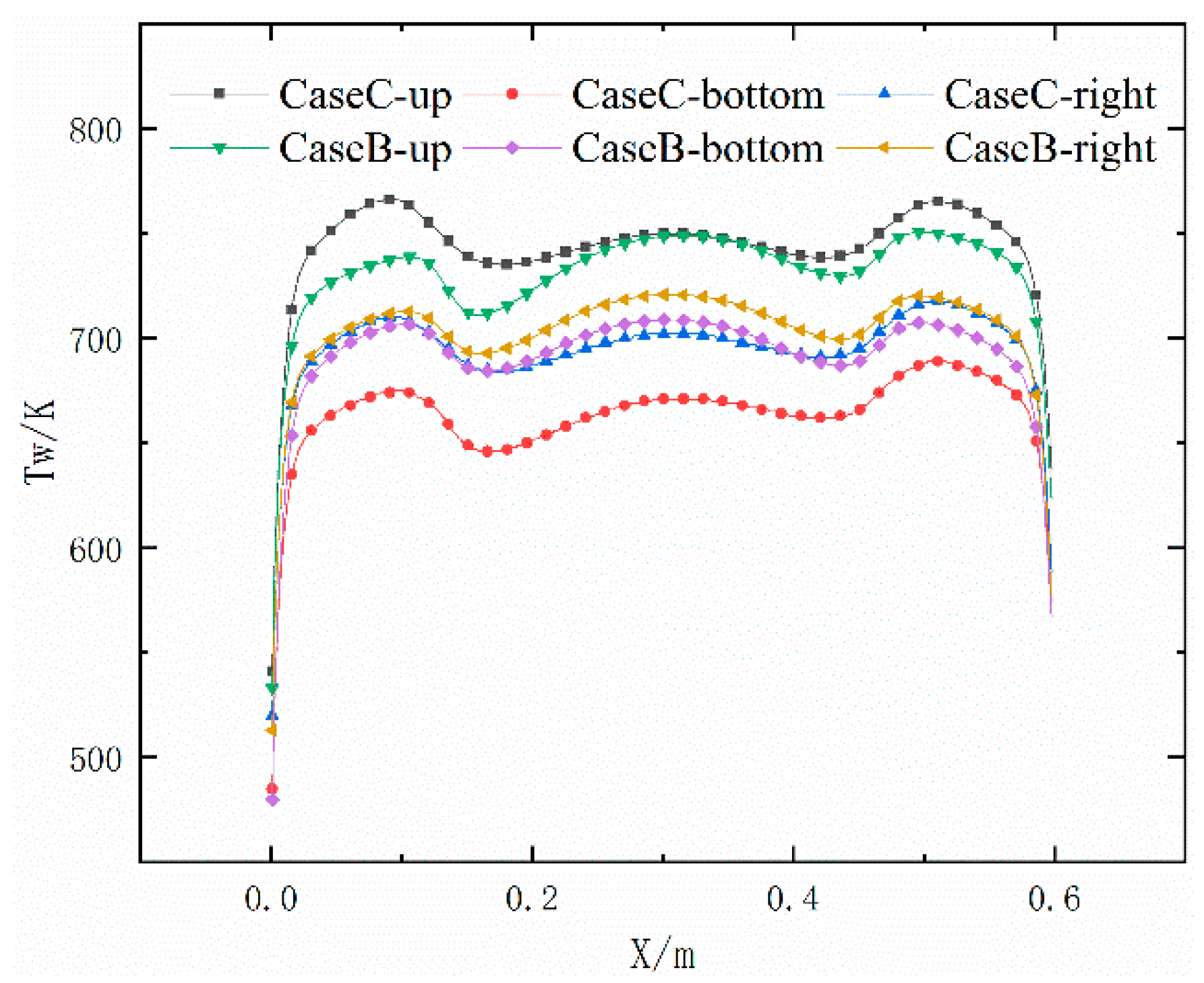
  • Compared to cooling channels with the same flow direction, the application of adjacent cooling channels with opposite flow directions is beneficial to the reduction in the maximum wall temperature. The maximum wall temperature is reduced by 9.07% only by changing the flow direction under current case, which prevents the occurrence of local high wall temperatures.
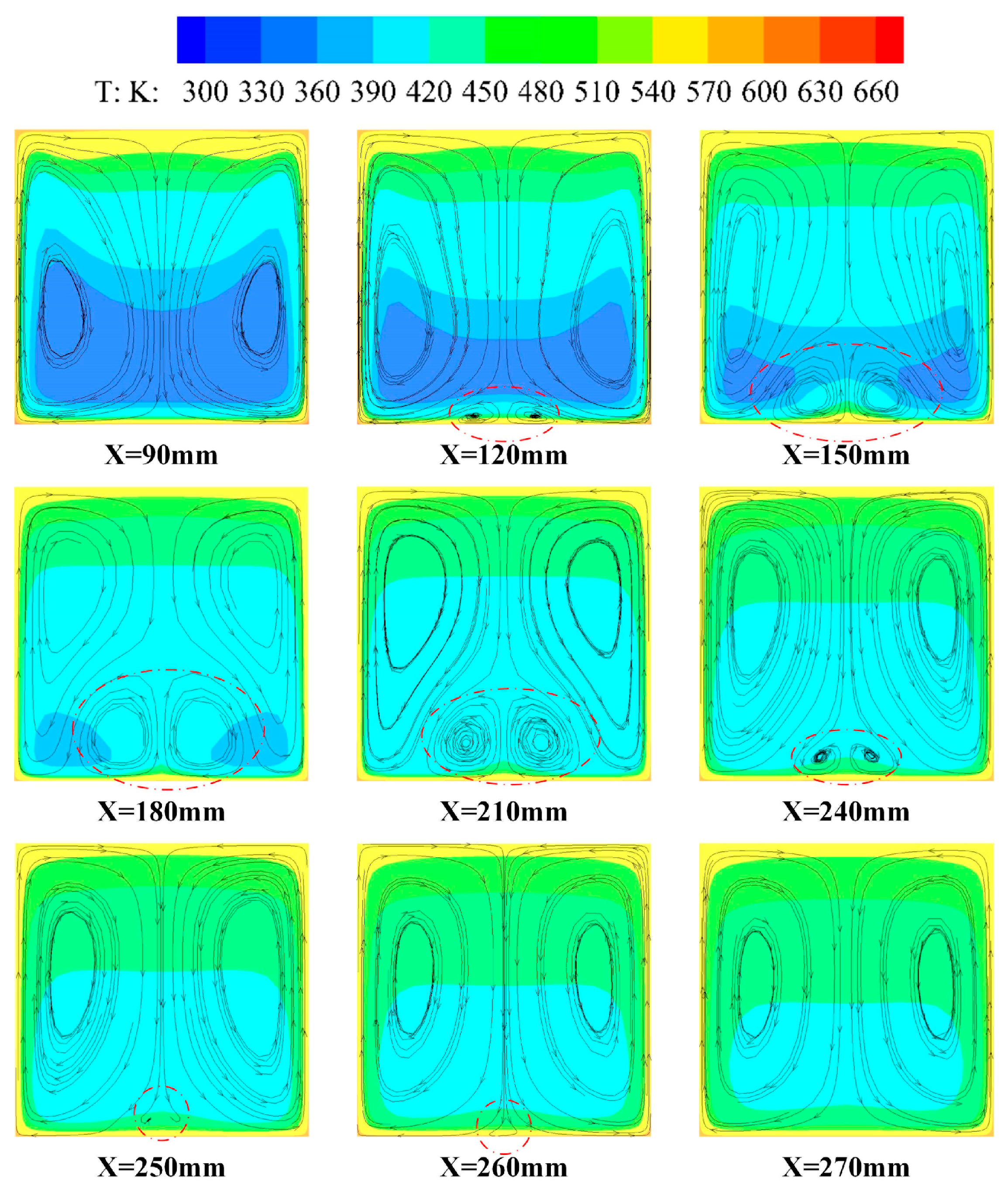
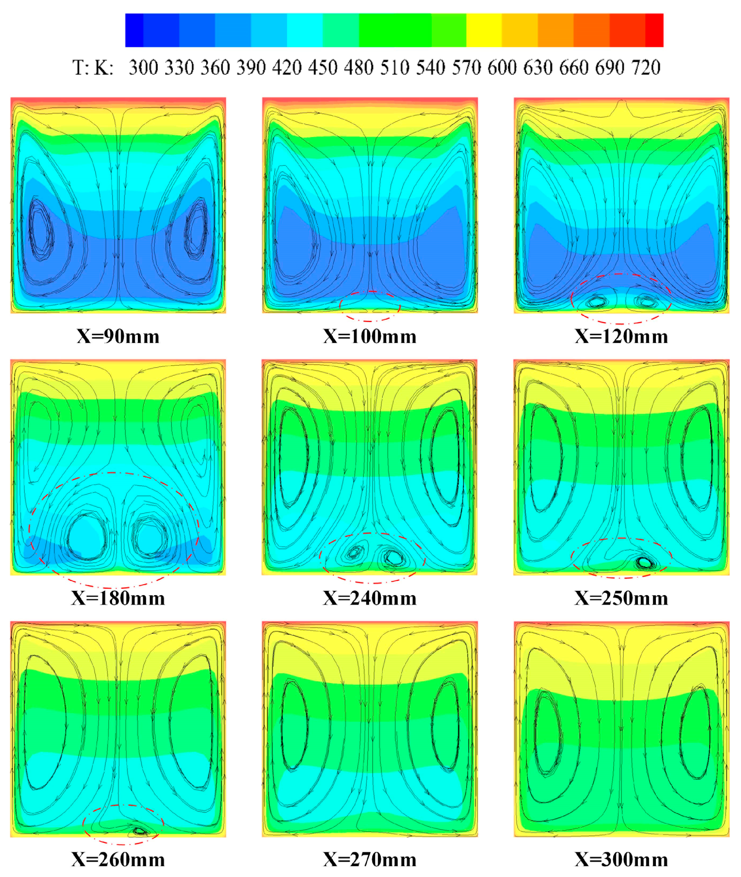
  • The development of two small recirculation zones along the flow direction can be observe in the cooling channels. With increasing heat flux, the occurrence range of the small recirculation zones obviously expands, and the asymmetry of the whole flow field becomes more obvious.
  • The gravity effect plays an important role in the generation of small recirculation zones in cooling channels. The small recirculation zones induced by the buoyancy force narrow, and flow asymmetry is inhibited when the gravity and heat flux directions remain the same. The occurrence of flow asymmetry may be closely related to the interaction between hot and cold fluids.

Author Contributions

Conceptualization, N.W.; methodology, C.L.; software, D.J.; validation, C.L., D.J. and S.W.; formal analysis, D.J.; investigation, N.W.; resources, K.Y.; data curation, D.J.; writing—original draft preparation, D.J.; writing—review and editing, Y.P.; visualization, J.L.; supervision, Y.P.; project administration, Y.P.; funding acquisition, C.L. All authors have read and agreed to the published version of the manuscript.

Funding

This research was funded by National Natural Science Foundation of China, grant number 12002373.

Institutional Review Board Statement

Not applicable.

Informed Consent Statement

Not applicable.

Data Availability Statement

Data is contained within the article.

Conflicts of Interest

The authors declare no conflict of interest.

Nomenclature

Dininner diameter (m)
Doutouter diameter (m)
Ppressure (MPa)
Qwall heat flux (W/m2)
Ttemperature (K)
Cpspecific heat of the fluid (J/kg·K)
Gmass flow rate (kg/h)
X, Y, Zstreamwise direction, normal direction and spanwise direction
Subscripts
wwall
ffluid

References

  1. Fry, R.S. A Century of Ramjet Propulsion Technology Evolution. J. Propuls. Power 2004, 20, 27–58. [Google Scholar] [CrossRef]
  2. Zhu, Y.; Peng, W.; Xu, R.; Jiang, P. Review on active thermal protection and its heat transfer for airbreathing hypersonic vehicles. Chin. J. Aeronaut. 2018, 31, 1929–1953. [Google Scholar] [CrossRef]
  3. Jeong, S.-M.; Choi, J.-Y. Combined Diagnostic Analysis of Dynamic Combustion Characteristics in a Scramjet Engine. Energies 2020, 13, 4029. [Google Scholar] [CrossRef]
  4. Ning, W.; Yu, P.; Jin, Z. Research status of active cooling of endothermic hydrocarbon fueled scramjet engine. Proc. Inst. Mech. Eng. Part G J. Aerosp. Eng. 2012, 227, 1780–1794. [Google Scholar] [CrossRef]
  5. Gascoin, N.; Abraham, G.; Gillard, P. Synthetic and jet fuels pyrolysis for cooling and combustion applications. J. Anal. Appl. Pyrolysis 2010, 89, 294–306. [Google Scholar] [CrossRef] [Green Version]
  6. DeWitt, M.J.; Edwards, T.; Shafer, L.; Brooks, D.; Striebich, R.; Bagley, S.P.; Wornat, M.J. Effect of Aviation Fuel Type on Pyrolytic Reactivity and Deposition Propensity under Supercritical Conditions. Ind. Eng. Chem. Res. 2011, 50, 10434–10451. [Google Scholar] [CrossRef]
  7. Sreekireddy, P.; Reddy, T.K.K.; Selvaraj, P.; Reddy, V.M.; Lee, B.J. Analysis of active cooling panels in a scramjet combustor considering the thermal cracking of hydrocarbon fuel. Appl. Therm. Eng. 2019, 147, 231–241. [Google Scholar] [CrossRef]
  8. Tu, J.; Jinlong, P.; Xianning, Y.; Lianzhong, C. Experimental Investigations on Active Cooling Thermal Protection Structure of Hydrocarbon-Fueled Scramjet Combustor in Arc Heated Facility. AIP Conf. Proc. 2016, 1770, 040021. [Google Scholar]
  9. Qin, J.; Bao, W.; Zhou, W.; Yu, D. Flow and heat transfer characteristics in fuel cooling channels of a recooling cycle. Int. J. Hydrogen Energy 2010, 35, 10589–10598. [Google Scholar] [CrossRef]
  10. Jiang, Y.; Xu, Y.; Qin, J.; Zhang, S.; Chetehouna, K.; Gascoin, N.; Bao, W. The flow rate distribution of hydrocarbon fuel in parallel channels with different cross section shapes. Appl. Therm. Eng. 2018, 137, 173–183. [Google Scholar] [CrossRef]
  11. Zhu, J.; Zhao, C.; Cheng, Z.; Lin, D.; Tao, Z.; Qiu, L. Experimental investigation on heat transfer of n-decane in a vertical square tube under supercritical pressure. Int. J. Heat Mass Transf. 2019, 138, 631–639. [Google Scholar] [CrossRef]
  12. Lei, Z.; Liu, B.; Huang, Q.; He, K.; Bao, Z.; Zhu, Q.; Li, X. Thermal cracking characteristics of n-decane in the rectangular and circular tubes. Chin. J. Chem. Eng. 2019, 27, 2876–2883. [Google Scholar] [CrossRef]
  13. Jiao, S.; Li, S.; Pu, H.; Dong, M.; Shang, Y. Experimental investigation on thermal cracking and convective heat transfer characteristics of aviation kerosene RP-3 in a vertical tube under supercritical pressures. Int. J. Therm. Sci. 2019, 146, 106092. [Google Scholar] [CrossRef]
  14. Jiang, P.-X.; Wang, Y.; Zhu, Y. Differential Global Reaction Model with Variable Stoichiometric Coefficients for Thermal Cracking of n-Decane at Supercritical Pressures. Energy Fuels 2019, 33, 7244–7256. [Google Scholar] [CrossRef]
  15. Pu, H.; Li, S.; Dong, M.; Jiao, S.; Wang, Y.; Shang, Y. Convective heat transfer and flow resistance characteristics of supercritical pressure hydrocarbon fuel in a horizontal rectangular mini-channel. Exp. Therm. Fluid Sci. 2019, 108, 39–53. [Google Scholar] [CrossRef]
  16. Zhu, K.; Xu, G.-Q.; Tao, Z.; Deng, H.-W.; Ran, Z.-H.; Zhang, C.-B. Flow frictional resistance characteristics of kerosene RP-3 in horizontal circular tube at supercritical pressure. Exp. Therm. Fluid Sci. 2013, 44, 245–252. [Google Scholar] [CrossRef]
  17. Asadi, M.; Xie, G.; Sunden, B. A review of heat transfer and pressure drop characteristics of single and two-phase microchannels. Int. J. Heat Mass Transf. 2014, 79, 34–53. [Google Scholar] [CrossRef]
  18. Pan, H.; Bi, Q.; Liu, Z.; Feng, S.; Feng, F. Experimental investigation on thermo-acoustic instability and heat transfer of supercritical endothermic hydrocarbon fuel in a mini tube. Exp. Therm. Fluid Sci. 2018, 97, 109–118. [Google Scholar] [CrossRef]
  19. Wang, H.; Wang, H.; Nie, W.; Su, L.; Yang, X. Investigation on the Mechanism of Thermoacoustic Instability of n-Decane at Subcritical Pressure. AIAA J. 2018, 56, 2635–2641. [Google Scholar] [CrossRef]
  20. Wang, Y.; Li, S.; Dong, M. Experimental investigation on heat transfer deterioration and thermo-acoustic instability of supercritical-pressure aviation kerosene within a vertical upward circular tube. Appl. Therm. Eng. 2019, 157, 113707. [Google Scholar] [CrossRef]
  21. Liu, B.; Zhu, Y.; Yan, J.-J.; Lei, Y.; Zhang, B.; Jiang, P.-X. Experimental investigation of convection heat transfer of n-decane at supercritical pressures in small vertical tubes. Int. J. Heat Mass Transf. 2015, 91, 734–746. [Google Scholar] [CrossRef]
  22. Wang, Y.; Li, S.; Dong, M. Numerical Study on Heat Transfer Deterioration of Supercritical n-Decane in Horizontal Circular Tubes. Energies 2014, 7, 7535–7554. [Google Scholar] [CrossRef] [Green Version]
  23. Toghraie, D. Numerical Thermal Analysis of Water’s Boiling Heat Transfer Based on a Turbulent Jet Impingement on Heated Surface. Phys. E Low Dimens. Syst. Nanostruct. 2016, 84, 454–465. [Google Scholar] [CrossRef]
  24. Pourfattah, F.; Motamedian, M.; Sheikhzadeh, G.; Toghraie, D.; Akbari, O.A. The numerical investigation of angle of attack of inclined rectangular rib on the turbulent heat transfer of Water-Al2O3 nanofluid in a tube. Int. J. Mech. Sci. 2017, 131-132, 1106–1116. [Google Scholar] [CrossRef]
  25. Parsaiemehr, M.; Pourfattah, F.; Akbari, O.A.; Toghraie, D.; Sheikhzadeh, G. Turbulent flow and heat transfer of Water/Al2O3 nanofluid inside a rectangular ribbed channel. Phys. E Low Dimens. Syst. Nanostruct. 2018, 96, 73–84. [Google Scholar] [CrossRef]
  26. Alipour, H.; Karimipour, A.; Safaei, M.R.; Semiromi, D.T.; Akbari, O.A. Influence of T-semi attached rib on turbulent flow and heat transfer parameters of a silver-water nanofluid with different volume fractions in a three-dimensional trapezoidal microchannel. Phys. E Low Dimens. Syst. Nanostruct. 2017, 88, 60–76. [Google Scholar] [CrossRef]
  27. Akbari, O.A.; Toghraie, D.; Karimipour, A. Numerical simulation of heat transfer and turbulent flow of water nanofluids copper oxide in rectangular microchannel with semi-attached rib. Adv. Mech. Eng. 2016, 8. [Google Scholar] [CrossRef] [Green Version]
  28. Ruan, B.; Huang, S.; Meng, H.; Gao, X. Flow dynamics in transient heat transfer of n-decane at supercritical pressure. Int. J. Heat Mass Transf. 2017, 115, 206–215. [Google Scholar] [CrossRef]
  29. Li, Y.; Sun, F.; Sunden, B.; Xie, G. Turbulent heat transfer characteristics of supercritical n -decane in a vertical tube under various operating pressures. Int. J. Energy Res. 2019, 43, 4652–4669. [Google Scholar] [CrossRef]
  30. Zhang, L.; Zhang, R.; Xiao, S.; Jiang, J.; Le, J. Experimental investigation on heat transfer correlations of n-decane under supercritical pressure. Int. J. Heat Mass Transf. 2013, 64, 393–400. [Google Scholar] [CrossRef]
  31. Wang, N.; Pan, Y. Correlation for heat transfer of RP-3 kerosene flowing in miniature tube at supercritical pressures. Mod. Phys. Lett. B 2020, 34. [Google Scholar] [CrossRef]
  32. Li, Y.; Chen, Y.; Zhang, Y.; Sun, F.; Xie, G. An Improved Heat Transfer Correlation for Supercritical Aviation Kerosene Flowing Upward and Downward in Vertical Tubes. J. Therm. Sci. 2019, 29, 131–143. [Google Scholar] [CrossRef]
  33. Feng, Y.; Cao, J.; Li, X.; Zhang, S.; Qin, J.; Rao, Y. Flow and Heat Transfer Characteristics of Supercritical Hydrocarbon Fuel in Mini Channels With Dimples. J. Heat Transf. 2017, 139, 122401–12240111. [Google Scholar] [CrossRef]
  34. Hosseinnezhad, R.; Akbari, O.A.; Afrouzi, H.H.; Biglarian, M.; Koveiti, A.; Toghraie, D. Numerical study of turbulent nanofluid heat transfer in a tubular heat exchanger with twin twisted-tape inserts. J. Therm. Anal. Calorim. 2017, 132, 741–759. [Google Scholar] [CrossRef]
  35. Jiang, Y.; Feng, Y.; Zhang, S.; Qin, J.; Bao, W. Numerical heat transfer analysis of transcritical hydrocarbon fuel flow in a tube partially filled with porous media. Open Phys. 2016, 14, 659–667. [Google Scholar] [CrossRef] [Green Version]
  36. Li, X.; Qin, J.; Zhang, S.; Cui, N.; Bao, W. Effects of Microribs on the Thermal Behavior of Transcritical n-Decane in Asymmetric Heated Rectangular Mini-Channels Under Near Critical Pressure. J. Heat Transf. 2018, 140. [Google Scholar] [CrossRef]
  37. Ahn, H.S.; Lee, S.W.; Lau, S.C. Heat Transfer Enhancement for Turbulent Flow Through Blockages With Round and Elongated Holes in a Rectangular Channel. J. Heat Transf. 2007, 129, 1611–1615. [Google Scholar] [CrossRef]
  38. Lei, Z.; He, K.; Huang, Q.; Bao, Z.; Li, X. Numerical study on supercritical heat transfer of n-decane during pyrolysis in rectangular tubes. Appl. Therm. Eng. 2020, 170, 115002. [Google Scholar] [CrossRef]
  39. Sengen, A.-L.; Herbstritt, F.; Gruenewald, M.; Heck, J. Experimental Investigation of the Convective Heat Transfer Coefficient in a Rectangular Microchannel. Chem. Ing. Tech. 2017, 89, 379–389. [Google Scholar] [CrossRef]
  40. Lu, Z.; Zhu, Y.; Guo, Y.; Jiang, P. Experimental Investigation of Convective Heat Transfer of Supercritical Pressure Hydrocarbon Fuel in a Horizontal Section of a Rotating U-Duct. J. Heat Transf. 2019, 141. [Google Scholar] [CrossRef]
  41. Sui, Y.; Teo, C.; Lee, P.; Chew, Y.; Shu, C. Fluid flow and heat transfer in wavy microchannels. Int. J. Heat Mass Transf. 2010, 53, 2760–2772. [Google Scholar] [CrossRef]
  42. Mohammed, H.; Gunnasegaran, P.; Shuaib, N. Numerical simulation of heat transfer enhancement in wavy microchannel heat sink. Int. Commun. Heat Mass Transf. 2011, 38, 63–68. [Google Scholar] [CrossRef]
  43. Kumar, V.R.; Balasubramanian, K.; Kumar, K.K.; Tiwari, N.; Bhatia, K. Numerical investigation of fluid flow and heat transfer characteristics in novel circular wavy microchannel. Proc. Inst. Mech. Eng. Part E J. Process. Mech. Eng. 2018, 233, 954–966. [Google Scholar] [CrossRef]
  44. Bazdar, H.; Toghraie, D.; Pourfattah, F.; Akbari, O.A.; Nguyen, H.M.; Asadi, A. Numerical investigation of turbulent flow and heat transfer of nanofluid inside a wavy microchannel with different wavelengths. J. Therm. Anal. Calorim. 2020, 139, 2365–2380. [Google Scholar] [CrossRef]
  45. Cheong, W.K.; Muezzin, F.N.B.A. Heat Transfer of a Double Layer Microchannel Heat Sink. Appl. Mech. Mater. 2013, 479, 411–415. [Google Scholar] [CrossRef]
  46. Shen, H.-M.; Jin, X.; Zhang, F.; Xie, G.; Sunden, B.; Yan, H. Computational optimization of counter-flow double-layered microchannel heat sinks subjected to thermal resistance and pumping power. Appl. Therm. Eng. 2017, 121, 180–189. [Google Scholar] [CrossRef]
  47. Liu, Y.; Xie, G.; Sunden, B.A. Effect of wall conduction on the heat transfer characteristics of supercritical n-decane in a horizontal rectangular pipe for cooling of a scramjet combustor. Int. J. Numer. Methods Heat Fluid Flow 2020. [Google Scholar] [CrossRef]
  48. Zhao, H.; Li, X.; Wu, X. Numerical investigation of supercritical water turbulent flow and heat transfer characteristics in vertical helical tubes. J. Supercrit. Fluids 2017, 127, 48–61. [Google Scholar] [CrossRef]
  49. Li, Y.; Sun, F.; Xie, G.; Sunden, B.; Qin, J. Numerical investigation on flow and thermal performance of supercritical CO2 in horizontal cylindrically concaved tubes. Appl. Therm. Eng. 2019, 153, 655–668. [Google Scholar] [CrossRef]
  50. Marcia, L.H. NIST Standard Reference Database 4. NIST Thermophysical Properties of Hydrocarbon Mixtures (SuperTrapp): Version 3.2; National Institute of Standards and Technology: Gaithersburg, MA, USA, 2007; pp. 3–36.
Figure 1. Schematic cross-sectional view of a typical scramjet cooling channel.
Energies 14 01071 g001
Figure 2. Computational domain in this paper: (a) case A: cooling channels with the same flow direction; (b) case B: cooling channels with opposite flow directions.
Energies 14 01071 g002aEnergies 14 01071 g002b
Figure 3. Cross-section of the grids.
Energies 14 01071 g003
Figure 4. Thermophysical data of n-decane at 3 MPa calculated with SUPERTRAPP software. (a) density and viscosity; (b) Cp and thermal conductivity.
Energies 14 01071 g004
Figure 5. Comparison of the numerical and experimental results of upward flow. (a) Fluid temperature; (b) Wall temperature.
Energies 14 01071 g005
Figure 6. Comparison of the numerical and experimental results of downward flow.
Energies 14 01071 g006
Figure 7. Temperature distributions of four side walls along the X-axis: (a) Case A, CH1; (b) Case A, CH2; (c) Case B, CH1; (d) Case B, CH2.
Energies 14 01071 g007
Figure 8. The fluid temperature distribution along the flow direction: (a) Case A; (b) Case B.
Energies 14 01071 g008
Figure 9. Bulk fluid temperature distribution along the X-axis.
Energies 14 01071 g009
Figure 10. Comparison of wall temperature along the X-axis with different heat flux.
Energies 14 01071 g010
Figure 11. The streamline diagram of the cross section at different positions in case B.
Energies 14 01071 g011
Figure 12. Streamline diagram of the cross section at different positions with the heat flux of: (a) 0.4 MW/m2; (b) 0.5 MW/m2.
Energies 14 01071 g012aEnergies 14 01071 g012b
Figure 13. Streamlines of cross section along the flow direction in case C.
Energies 14 01071 g013
Figure 14. Comparison of the wall temperature distribution along the X-axis in case B and case C.
Energies 14 01071 g014
Figure 15. Two-dimensional streamlines at Z = 2 mm visualized under a uniform magnitude: (a) temperature; (b) velocity.
Energies 14 01071 g015
Table 1. Simulation results for the three sets of meshes.
Mesh Number (Million)Temperature of Outlet 1 (K)Temperature of Outlet 2 (K)
1.74625.69625.69
2.85625.86625.86
4.60625.78625.78
Publisher’s Note: MDPI stays neutral with regard to jurisdictional claims in published maps and institutional affiliations.

