Article

Assessing the Energy-Saving Potential of a Dish-Stirling Con-Centrator Integrated Into Energy Plants in the Tertiary Sector

by
Stefania Guarino
,
Pietro Catrini
*,
Alessandro Buscemi
,
Valerio Lo Brano
and
Antonio Piacentino
Department of Engineering, University of Palermo, 90133 Palermo, Italy
*
Author to whom correspondence should be addressed.
Energies 2021, 14(4), 1163; https://doi.org/10.3390/en14041163
Submission received: 20 January 2021 / Revised: 17 February 2021 / Accepted: 19 February 2021 / Published: 22 February 2021
(This article belongs to the Special Issue Integrated Solar Thermal Systems)

Abstract

:
Energy consumed for air conditioning in residential and tertiary sectors accounts for a large share of global use. To reduce the environmental impacts burdening the covering of such demands, the adoption of renewable energy technologies is increasing. In this regard, this paper evaluates the energy and environmental benefits achievable by integrating a dish-Stirling concentrator into energy systems used for meeting the air conditioning demand of an office building. Two typical reference energy plants are assumed: (i) a natural gas boiler for heating purposes and air-cooled chillers for the cooling periods, and (ii) a reversible heat pump for both heating and cooling. For both systems, a dish-Stirling concentrator is assumed to operate first in electric-mode and then in a cogenerative-mode. Detailed models are adopted for plant components and implemented in the TRNSYS environment. Results show that when the concentrator is operating in electric-mode the electricity purchased from the grid decreases by about 72% for the first plant, and 65% for the second plant. Similar reductions are obtained for CO2 emissions. Even better performance may be achieved in the case of the cogenerative-mode. In the first plant, the decrease in natural gas consumption is about 85%. In the second plant, 66.7% is the percentage increase in avoided electricity purchase. The integration of the dish-Stirling system allows promising energy-saving and reduction in CO2 emissions. However, both a reduction in capital cost and financial support are needed to encourage the diffusion of this technology.

1. Introduction

The increasing emission of greenhouse gases (GHG) into the atmosphere, primarily carbon dioxide (CO2), represents the major cause of the rise in global average temperature [1]. The energy production from fossil fuel, the consumption of energy in the industrial and transport sectors, and the energy used to meet the heating and cooling demands of buildings are the main human activities contributing to CO2 emissions [2].
In this scenario, greater employment of renewable technologies for a distributed generation would lead to a large amount of avoided emissions, while improving the reliability of energy supply and reducing the energy withdrawal from the national grid. In particular, the building sector accounts for about 30% of global energy consumption [3], with a consequence of about 10 GtCO2 emissions on a global scale in 2019 [4].
The use of renewable energy sources along with energy-saving measures are the two main routes to decarbonizing the building sector [5]. However, the integration of renewable technologies with buildings is challenged by the need to align production and demand energy profiles, which often do not match [6]. In this regard, it is necessary to consider, on the one hand, the energy needs (in terms of electricity, energy for heating and cooling) of buildings which is largely variable over time, and, on the other hand, the aleatory nature of renewables such as solar and wind energy [7]. Then, to mitigate intermittency problems and to perform peak shaving, the use of renewable technologies cannot disregard the installation of efficient energy storage systems or energy auxiliary systems [8].
Among solar technologies for electricity or heat production, the most promising and efficient systems are Concentrating Solar Power (CSP) systems [9]. For instance, if installed in remote regions like islands where fossil fuel-based generation systems are usually adopted, they could lead to a significant reduction in CO2 emissions [10]. Thanks to the continuous technological development, the CSP technologies are expected to cover up to 6% of the world’s energy demand by 2030 and 12% by 2050 with promising energy efficiency [11].
There are four types of CSP technologies and they can be classified into line-focusing technologies, such as parabolic trough systems and linear Fresnel reflectors, and point-focusing technologies, such as central solar tower systems and parabolic dish systems [12].
Among CSP technologies, parabolic dish solar concentrators are characterized by the highest efficiency in the conversion of solar energy into electricity [13], and the highest values of operating temperature, and concentration ratio. Moreover, such collectors occupy a smaller area of land per installed peak power than other types of CSP systems [14]. The typical capacity of these systems ranges between 3–30 kWp, making it suitable for small-scale applications [15]. Parabolic-dish systems are also eligible for installation in water-scarce areas, since they do not require water for cooling or operational processes [16].
The integrated engine moves jointly with the paraboloidal collector and therefore both the support structure and tracking system must be solid and robust, thus affecting the total cost of the system [17]. The high initial cost is the main limit to the commercialization of the parabolic dish system [18], and it strongly affects the Levelized Cost of Energy (LCOE), which is not as competitive as parabolic trough or central solar towers systems [19]. Furthermore, CSP systems such as parabolic troughs enjoy the advantage of being more easily coupled to thermal storage systems compared to a parabolic dish [13]. For these reasons, the latter technologies are installed in most of the CSP plants in operation or under construction worldwide [20].
In general, the development of more experimental and demonstration plants could encourage and improve the commercial penetration of parabolic dish technology, which is less mature and widespread than the others [21].
Parabolic dish solar concentrators, equipped with a biaxial tracking system, use a paraboloid-shaped mirror to collect incident normal solar irradiation and concentrate it at a receiver. The receiver, which can be a cavity or made of small tubes, transfers the high-temperature thermal energy to a heat transfer fluid (air, helium, or hydrogen), which evolves in a thermodynamic cycle (Stirling cycle or Brayton cycle) to perform the conversion from heat to mechanical energy. Finally, an alternator is used to generate electric energy [22].
The dish-Stirling solar concentrator, which couples a paraboloidal reflector with a Stirling engine, is the newest CSP technology to be developed and the most efficient in solar-to-electricity conversion [23]. Furthermore, such systems, whose producibility is highly dependent on the level of normal solar irradiation of the installation site [24], can be employed in several applications [9]. This technology can be coupled with a thermal storage system [25], or it can be hybridized to extend the production period to hours of the day during which solar radiation is not available [26], it can be used in both centralized [27] and distributed power generation for electricity supplying remote rural areas [28], and it can also be combined with desalination systems to produce potable water [29].
Other interesting applications of dish-Stirling technology include the possibility to operate it in pure electric mode or cogenerative mode [30]. Referring to the pure electric mode, in [31], the authors analysed and compared the energy performance of a photovoltaic system and a dish-Stirling system integrated into a building located in Lebanon to meet the electricity demand. With the criterion of maximising the use of the building rooftop area, it was observed that the dish-Stirling system, with a peak electrical power of 25 kWp, covers 68% of the total electric energy demand, compared to 12% obtained using the PV system (9.3 kWp).
Regarding the cogenerative mode, research has shown the possibility of using a dish-Stirling system in the building sector to satisfy energy demand for heating, cooling, ventilation, domestic hot water, and electricity. In [32], energy, environmental and economic analyses of a dish-Stirling cogenerative system (10 kWp), covering the electricity, heating, and cooling energy demands of a residential building, were carried out. Since the building energy requirements and the engine output power depend on the climatic conditions and the level of solar beam irradiation, the reference building was considered to be located in five different cities in Iran achieving average primary energy savings of about 139 MWh/y. In [33], the modelling and optimization of a micro-CHP system with a solar-powered Stirling engine were carried out. This system achieved an energy-saving rate of 15% during most of the year for a reference building located in three different Iranian cities. In [34], a combined CHP plant is proposed for the first time, implementing a dish-Stirling collector field, a seasonal geothermal storage, and a water-to-water heat pump system. The cogeneration plant has been designed both to supply thermal energy to the heating system of a non-residential building at Palermo University and to produce electrical energy. The results of the simulations show that by installing a single dish-Stirling concentrator, it is possible to cover 59% of the building annual thermal loads using the energy produced by the solar system, with a 55% reduction in CO2 emissions.
In this framework, the present paper assesses the benefits achievable by integrating the dish-Stirling concentrator into energy plants used to cover the energy demand of tertiary buildings. Two typical plants for space heating and cooling are identified to be eligible for the integration of this technology. The first one consists of systems that use natural gas and electricity, while the second one includes only electrically-driven systems. Meanwhile, to improve the achievable energy savings, two alternative operating strategies of the solar concentrator are proposed. More specifically, a fully electric mode is compared to a cogenerative mode, where the heat recovered from the Stirling engine is used to meet heating demand. Two further contributions of the proposed manuscript could be identified as follows:
  • the analysis proposes the integration of the detailed modelling of the dish-Stirling concentrator with the ones of the heat pump and chiller. Such an approach allows for a better understanding of the plant behavior, along with a more reliable assessment of the energy-saving and avoided CO2 emissions.
  • the study investigates the feasibility of a cogeneration system based on the dish-Stirling technology, in localities characterized by Direct Normal Irradiation (DNI) lower than 2000 kWh/m2/y.
To explore these topics, an office building located in Palermo (Southern Italy) is assumed as a case study. Two energy plants commonly adopted in this sector are considered: (i) a natural gas (NG) boiler for meeting thermal demand during the winter and an air-cooled chiller during the summer; and (ii) a reversible heat pump (HP) for providing both heating and cooling. In both plants, the possibility to operate the concentrator in electric or cogenerative mode is investigated. The numerical model of the dish-Stirling systems was validated by experimental data collected during the monitoring of the facility test site of Palermo [24]. The energy demands of the selected case study were available from energy audits performed in the field. A simplified economic analysis is also carried out to highlight factors that could affect the economic viability of the proposed investments.
The paper is structured as follows:
  • in the second section, detailed modelling of all subsystems comprising the energy plant is presented;
  • in the third section a description of the case study and the investigated energy systems configurations is provided;
  • in the last section, the results are presented and discussed in detail.

2. Materials and Methods

In this section, the models of the main plant components are explained in detail. Such models are then used to dynamically simulate the operation of the investigated energy plants.

2.1. Energy Model of the Dish-Stirling Solar Concentrator

To assess the annual energy production of the dish-Stirling solar concentrator, the numerical model presented in the literature [24] was taken as a reference. For the sake of completeness, a brief description is provided here and for more details, the reader is invited to refer to the cited reference. A scheme of the energy balance of the dish-Stirling concentrator is shown in Figure 1. The solar power ( Q ˙ s u n ) incident on the collector mirrors can be calculated using Equation (1).
Q ˙ s u n = I b A n
where: I b is the solar beam radiation and A n is the net useful mirror area of the collector, the net aperture area of the dish.
The role of the mirror dish is to collect the incident solar beam radiation, reflect off and concentrate it on the receiver. However, it is necessary to consider that the concentrator is affected by optical losses and that the mirrors could be soiled. Therefore, the thermal power that is concentrated on the receiver ( Q ˙ r , i n ) can be calculated as shown in Equation (2),
Q ˙ r , i n = Q ˙ sun η o η cle
where: η o is the optical efficiency of the solar concentrator and η c l e is the mirrors cleanliness index.
Furthermore, using Equation (3), it is possible to calculate the thermal power dissipated by convection and radiation from the receiver to the external environment ( Q ˙ r , out ) as a result of the high temperature reached.
Q ˙ r , out = A r [ h r ( T r T air ) + σ ε r ( T r 4 T sky 4 ) ]
In Equation (3), A r is the aperture area of the receiver, h r is the effective convective heat transfer coefficient of the receiver, T r and T air are the receiver and external air absolute-temperatures respectively, σ is the Stefan-Boltzmann constant, ε r is the receiver emissivity, and, finally, T sky is the equivalent black-body temperature of the sky. This last temperature (expressed in Kelvin) was calculated using the empirical expression shown in Equation (4) [35].
T sky = 0.0552 ( T air ) 1.5
Thus, the thermal power that the receiver transfers to the Stirling engine ( Q ˙ S , in ) can be determined by the following difference:
Q ˙ S , in = Q ˙ r , in Q ˙ r , out
The mechanical output power of the Stirling engine ( W ˙ S ) can be formulated as in Equation (6).
W ˙ S = ( a 1 Q ˙ S , in a 2 ) R T
where, a 1 and a 2 are two fitting parameters of the mechanical efficiency curve of the Stirling engine, and R T is the correction factor defined as the ratio between the reference temperature ( T 0 = 25 °C) and the external-air temperature expressed in Kelvin [24]. Finally, using Equation (7), it is possible to calculate the net electric output power of the dish-Stirling solar concentrator ( E ˙ n ), where E ˙ p ave represents the average value of the parasitic electric consumption (tracking and cooling-engine systems) and η cle ave is the average cleanliness index of the collector mirrors.
E ˙ n = ( η e η o η cle ave a 1 A n R T ) I b [ η e ( a 1 Q ˙ r , out + a 2 ) R T + E ˙ p ave ]
From the annual values of both the solar input energy to the collector ( Q sun ) and the net electric output energy ( E n ), the solar-to-electricity generation efficiency ( η G ) is defined as in Equation (8).
η G = E n Q sun

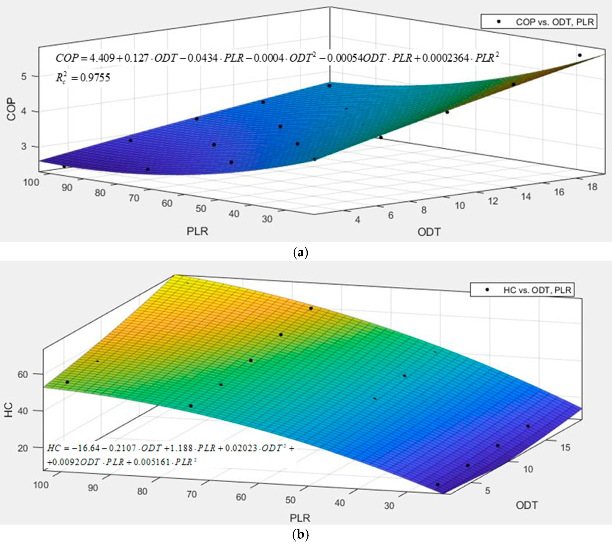
2.2. Technical Features and Modelling of Reversible Air-to-Water Heat-Pump and Air-Cooled Chiller

As will be shown in Section 3, the use of a reversible air-to-water heat pump and an air-cooled chiller will be hypothesized in this paper. The technical features of the two reference systems used for developing models of the operation of these systems are shown in Table 1. In particular, the cooling/heating capacities were selected based on the peak of the cooling/heating demand of the case study. For all of them, R410A is assumed as the refrigerant, and Electronic Expansion Valve (EEV) is used as the metering device. Brazed plate heat exchangers are used to heat and cool water. In the air-cooled chiller, a fin and tube heat exchanger with induced-draft fans is used on the condenser airside. Each unit is equipped with scroll compressors. The delivered cooling/heating capacity is controlled by activating/deactivating one compressor at a time for the air-cooled chiller. Conversely, a variable frequency drive is used on the heat pump.
Simulations of full-load and part-load operation were carried out using plant simulator IMST-ART v.3.80 [36]. This tool allows the performance of 1-D simulations for vapor-compression chiller systems, relying on detailed thermohydraulic modelling of heat exchangers, refrigerant lines, and accessories. Energy consumption and efficiency of compressors were evaluated using the “catalogue data” option, which converts data from commercial compressor catalogues into efficiency and consumption curves. A constant 3 °C superheat at the evaporator outlet was assumed, thus replicating the operating mode of EEVs.
In Figure 2, the Coefficient of Performance (COP) and the Heating Capacity (HC) of the reversible heat pump are plotted versus the outdoor air temperature (ODT) and the part load ratio (PLR). The black points in Figure 2 were obtained from the IMST-Art simulations at full (PLR = 100) and part-load conditions (PLR < 100).
Then, a multivariable regression was adopted to model the dependence of COP and HC from the two mentioned variables. The resulting equations are shown in the cited figures along with the corrected R-square. Similar graphs were obtained for the cooling-mode of the HP and the air-cooled chiller, not shown here for the sake of brevity. However, it was not possible to check the accuracy of the results since experimental data were not available for the investigated systems. Nevertheless, some published papers investigated the accuracy of simulation results from IMST-Art for chiller systems [37] commercial freezers [38], and heat pumps [39]. As shown in [38], experimental cooling capacity and power consumption are predicted by the software within a ±10% error band. Furthermore, the experimental evaporation and condensation temperatures are predicted within an error band of ±3 K. Other validation studies can be found in the following reference [36].

3. Description of the Case Study

An office building located in Palermo (Italy, 38.11° N; 13.36° E) was selected as a case study. In Figure 3, the following profiles are shown:
  • the yearly cooling demand (Figure 3a);
  • the thermal demand which accounts for space-heating and domestic hot water (DHW) (Figure 3b);
  • the electricity demand related to the lighting system and office equipment operation (Figure 3c).
Such profiles were available from energy audits performed in the framework of previous research [40].

3.1. Description of the Reference Dish-Stirling Concentrator

The reference system is the dish-Stirling concentrator with a 32 kWe net peak electrical power and operating at the facility test site of the University of Palermo. A picture of it is shown in Figure 4. The most relevant technical data concerning the considered dish-Stirling system are summarized in Table 2.
The main subsystems of the dish-Stirling concentrator are the collector, the Power Conversion Unit (PCU), and the tracking system. The reflector has the shape of a paraboloid and consists of an assembly of 104 facets of mirrors with a double curvature and a sandwich structure, with a glass upper surface characterized by a high reflection coefficient (ρ = 0.95 for clean surface). The mirror dish has a diameter of 12 m and an effective aperture area of 106 m2. On the focal axis of the paraboloid, at a focal length of 7.45 m, the PCU is fixed and includes the receiver, the Stirling engine, and the electric generator. The collector concentrates the collected solar radiation onto the aperture area of the receiver. The biaxial tracking system maintains a continuous and perfect alignment between the focal axis of the paraboloid and the direction of the sun’s rays. Subsequently, the receiver absorbs the solar thermal energy, making it available to the hot side of the Stirling engine in the form of high-temperature thermal energy. Here, the hydrogen reaches the operating conditions of 720 °C and 200 bar. Simultaneously with the continuous delivery of heat by the receiver on the hot side of the engine, a water-fed cooling system removes thermal energy on the cold side (outlet temperature of the water around 40 °C), which is dissipated into the environment via a dry-cooler. Thus, the Stirling engine converts high-temperature thermal energy into mechanical energy. Finally, an electric generator converts the mechanical output energy of the Stirling engine into electricity.
According to the energy model shown in Section 2.1, the main variables influencing the producibility of the dish-Stirling system are the solar beam irradiation ( I b ), the external air temperature ( T air ), and the level of soiling of the mirrors ( η cle ). Figure 5a depicts the hourly frequency distribution of the solar beam irradiation with a bin of 50 W/m2 and the average air temperature values calculated for each interval, referred to Typical Meteorological Year (TMY) provided by the Meteonorm solar database for Palermo [41]. Meteonorm uses input data obtained by interpolating observed ground-based data, mainly global and diffuse radiation, along with the support of satellite images. Furthermore, the software takes into account the attenuation of direct solar radiation due to atmospheric turbidity, i.e., the presence of water vapor and aerosol particles, in the solar radiation modelling [42].
As shown in Figure 5a, the hourly frequency distribution of I b for Palermo presents two peaks: one between 600 and 650 W/m2 and the other one between 700 and 750 W/m2. Both ranges are characterized by an average air temperature of approximately 23 °C. The annual normal solar irradiation value is equal to 1932.61 kWh/m2/y. Based on Meteonorm solar data and the reference energy model [24], the electrical production of the dish-Stirling system closely follows the seasonal trend of I b , as shown in Figure 5b. From simulations carried out in the present research, the cumulative annual production was found to be 46 MWh in Palermo.

3.2. Description of the Investigated Scenarios

Two alternative energy systems were assumed as reference plants to cover the demands of the case study. Such systems, here following indicated as System no. 1 and System no. 2, are representative of typical plants used in the tertiary sector for air-conditioning demand. Schemes of these are shown in Figure 6. Note that:
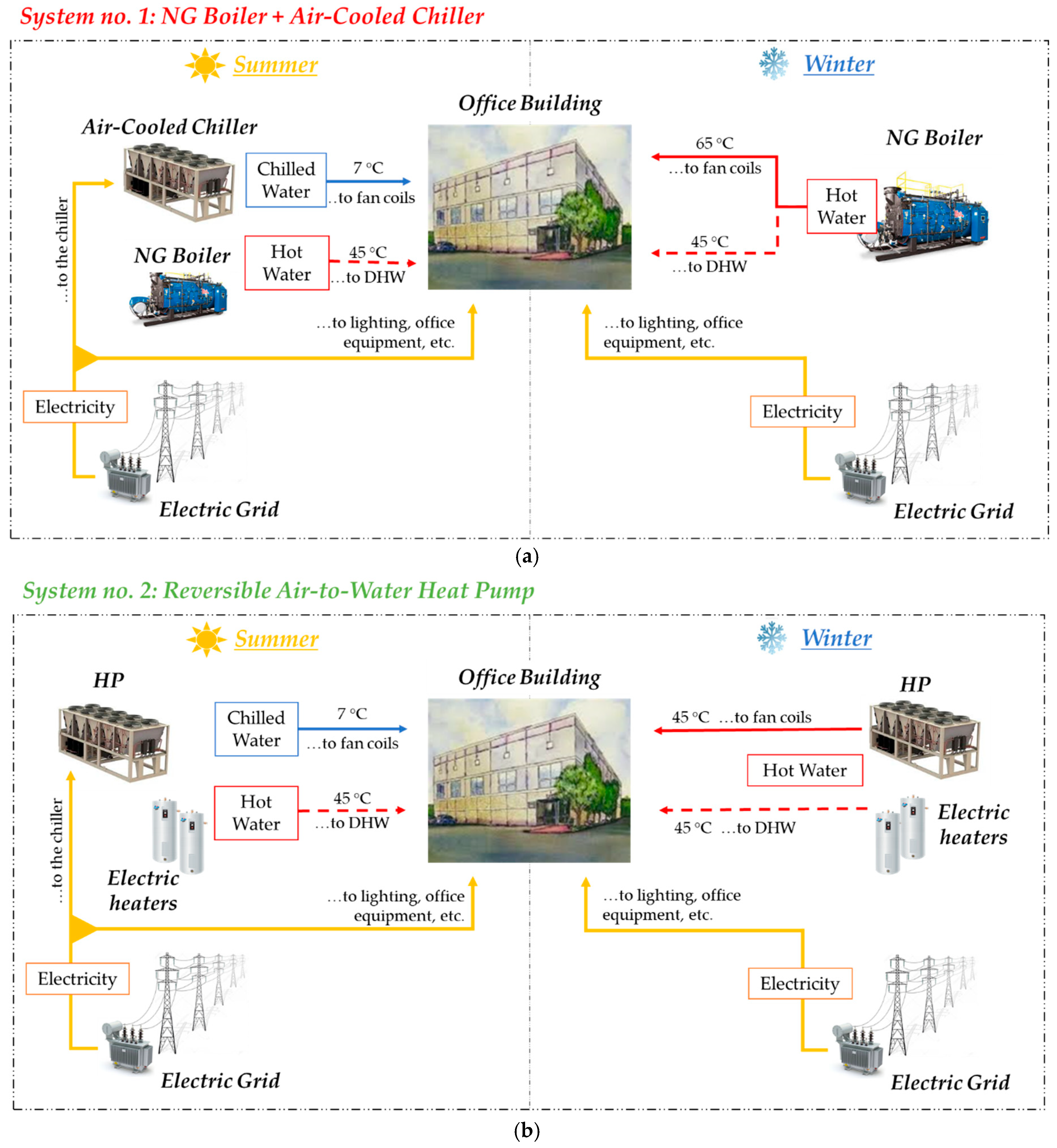
  • in System no. 1 (Figure 6a), an NG boiler is used to cover the thermal demand during the winter. In particular, hot water at 65 °C is supplied to fan coil units, and hot water at 45 °C to meet the DHW demand. Conversely, an air-cooled chiller covers the cooling demand during the summer. The electricity consumed by the lighting, office equipment, and the air-cooled chiller is purchased from the local grid;
  • in System no. 2 (Figure 6b), a reversible air-to-water HP covers both heating and cooling demands. Regarding DHW, electric heaters are used.
In both systems, it was assumed to integrate the dish-Stirling solar concentrator presented in Section 3.1. In particular, the following operating strategies were examined:
  • electric-mode: the dish-Stirling system produces only electricity, and heat is not recovered;
  • cogenerative-mode: the dish-Stirling system produces both electricity and heat. To make such a heat flow useful for air-conditioning purposes, the temperature of the water exiting the cooler of the Stirling engine is increased from 40 °C to 50 °C. Such a temperature increase is achieved by shutting off the dry-cooler. A reduction in the efficiency and electric power of the solar concentrator is expected due to the higher compression temperature of the engine. However, the assumed increase of the Stirling-engine cold side temperature (about 10 °C) slightly affects the engine efficiency (about −0.05% is the observed reduction), according to the following experimental study [43].
Based on the previous management strategies, different scenarios could be conceived when the dish-Stirling system is integrated. For Systems no. 1, the schemes of the two scenarios are shown in Figure 7. Note that:
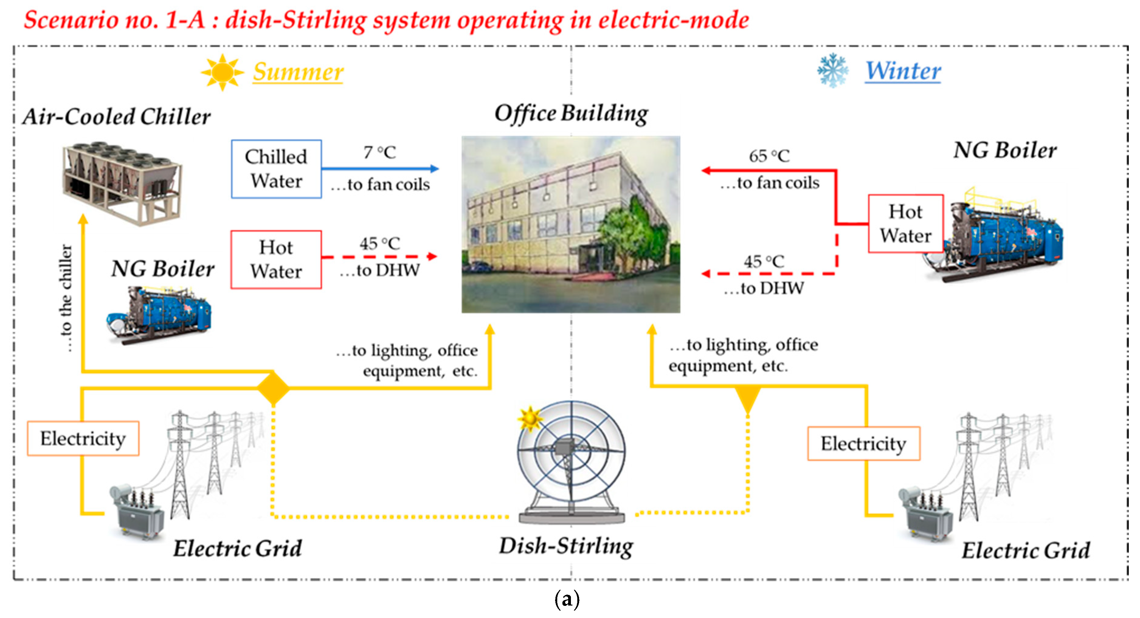
  • Scenario no. 1-A: as shown in Figure 7a, the dish-Stirling system produces only electricity which is used differently during the year. In particular, during the winter, such electricity is consumed by the lighting system and office equipment. Conversely, during the summer, it is also used to drive the air-cooled chiller. The thermal demand is covered using the NG boiler.
  • Scenario no. 1-B: as shown in Figure 7b, the dish-Stirling system produces both electricity and heat, used differently throughout the year. In particular, during the winter, the recovered heat is supplied to the air conditioning system. As a consequence, a fraction of thermal demand is not met by the boiler, and the amount of NG consumed decreases. Moreover, the produced electricity flow is consumed by the lighting system and office equipment. During the summer, the produced electricity is used to supply the air-cooled chiller, the lighting system, and office equipment. However, the heat flow recovered from the Stirling engine is at 40 °C since only DHW is needed. Indeed, it is not convenient to recover heat at a higher temperature which would reduce the electric power.
Like System no. 1, two scenarios were proposed for System no. 2, which are shown in Figure 8. Note that:
  • Scenario no. 2-A: as shown in Figure 8a, the dish-Stirling system produces only electricity which is used to operate the HP during the year. In those hours of low electricity demand, the electricity surplus is sold to the grid.
  • Scenario no. 2-B: as shown in Figure 8b, the dish-Stirling system operates in a cogenerative mode. In particular, like Scenario 1-B, during the winter, the recovered heat flow is used to supply the air-conditioning system, while the electricity is consumed mainly by the HP. Conversely, during the summer, the produced electricity is used to drive the HP, the lighting systems, and office equipment. Moreover, in this scenario, like Scenario 1-B the heat flow recovered from the Stirling engine is only used for DHW purposes.

3.3. Notes on Performed Simulations and Definition of the Environmental and Economic Indicators

The models of the main plant components previously described were implemented and solved by TRNSYS [44] software. The dynamic simulation of the investigated plant configurations was performed on a one-hour step.
Concerning the achievable environmental benefits, only the reduction in CO2 emissions was considered. Such a reduction was quantified by considering that the amount of electricity produced by the dish-Stirling system is not purchased from the electricity generation system of the country where the plant is operated anymore. Equation (9) was used for this purpose, where the emission factor μ e CO 2 quantifies the kilograms of CO2 emitted per kilowatt-hour of saved electricity ( E sav ). For instance, in Italy, according to [45], the emissions factor was estimated to be 0.485 kgCO2/kWhel.
C O 2 av = μ e CO 2 E sav
In Equation (9), C O 2 av is measured in kilograms per year. The same approach was used to calculate the avoided CO2 emissions resulting from the reduction in natural gas consumption. In this case, the emission factor μ NG CO 2 was assumed to be 0.19 kgCO2/kWhNG.
The total installed cost of the dish-Stirling unit of Palermo amounted to 200,525 € ( I 0 ). This cost was evaluated by taking into account the real costs incurred for the realization of this facility test site in 2017. To assess the economic feasibility of the four analyzed scenarios, the Net Present Value (NPV) and the Discounted Payback Time (DPBT) of the investment were assumed as economic and risk indicators.
The NPV was calculated according to Equation (10),
N P V = t = 1 n C F t ( 1 + r ) t
where: n is the useful lifetime of the plant set equal to 25 years, t is the t-th year of the lifetime of the plant, C F t [€] is the corresponding cash flow and r [-] is the discount rate set to 5%. While the DPBT [y] is defined as the number of years (t) required for the initial total investment to be re-paid and was determined according to Equation (11).
D P B T = t   |   t = 0 n C F t ( 1 + r ) t 0

4. Results and Discussion

Results obtained for reference System no. 1 and System no. 2 are shown in Table 3 and Table 4. It was found that:
  • for System no 1 (see Table 3) the NG consumed to cover the thermal demand was equal to 3970.4 Sm3/y. Conversely, electricity accounted for 63.64 MWhe/y. The amount of CO2 emitted for operating this plant was 38,107 kgCO2/y. Almost 81% of these emissions was due to the electricity purchase from the grid, while 19% was due to NG consumed by the boiler;
  • for System no. 2 (see Table 4), since a reversible HP covers both cooling and heating demand, only electricity was consumed throughout the year. The annual amount was found to be 71.45 MWhe/y, which led in turn to the emissions of 34,653 kgCO2/y of CO2.

4.1. Results for Improved System No. 1: Scenario No. 1-A and 1-B

Results for the improved configurations of Systems no. 1 shown in Figure 9, are presented and discussed in the following two subsections.

4.1.1. Results for Scenario 1-A

As shown in Figure 7a, in this case, the dish-Stirling system is operated in electric-mode. In Figure 9a, the annual electricity produced by the solar concentrator is plotted with the aggregated electricity demand of the case study (which accounts for the electricity consumed by the lighting systems, office equipment, and chiller). Note that:
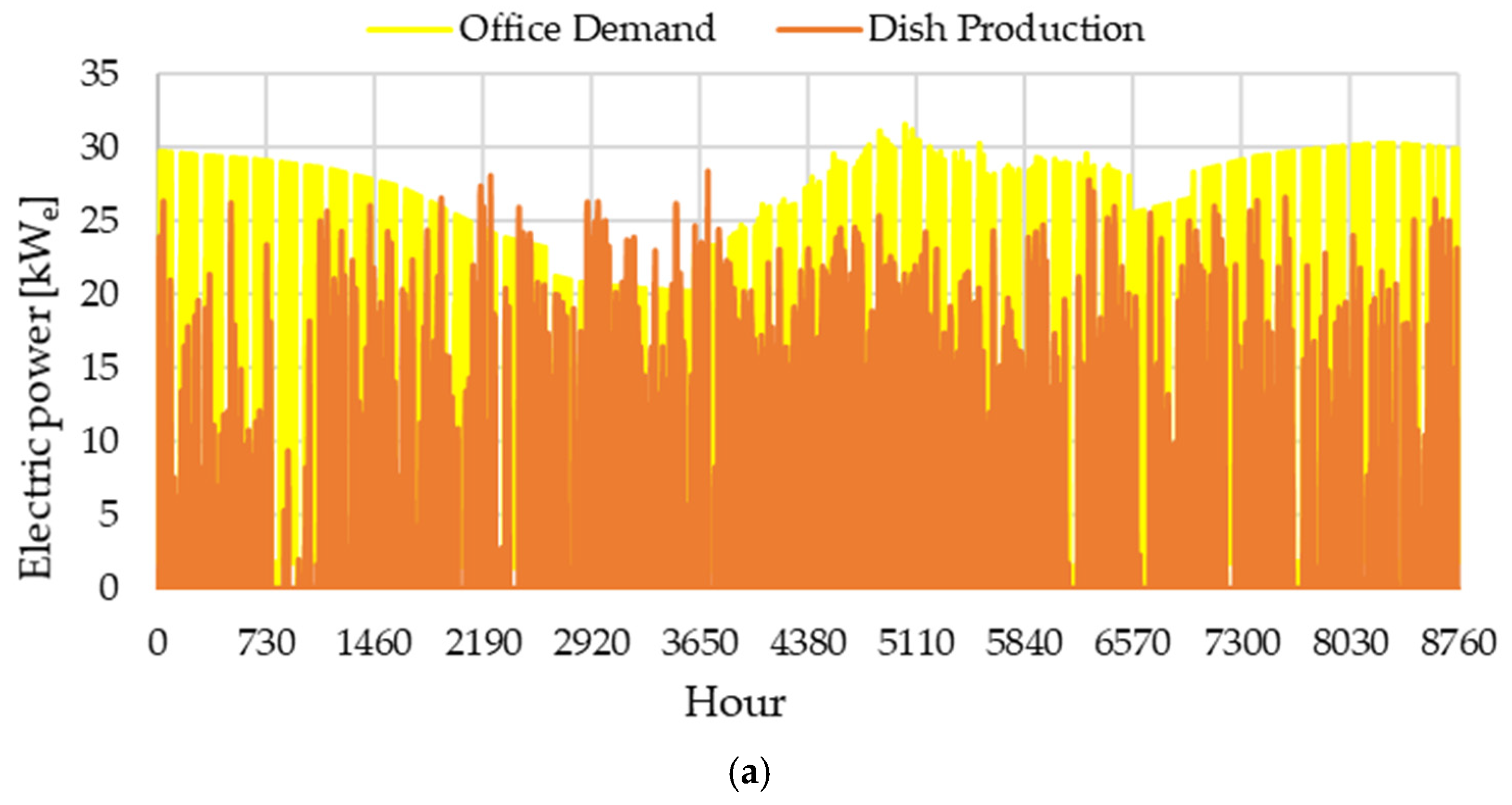
  • a large share of the aggregated electricity demand (yellow profile in Figure 9a) is met by using the electricity produced from the dish-Stirling system (orange profile). The fraction of electricity demand which is not covered by the concentrator is purchased from the grid;
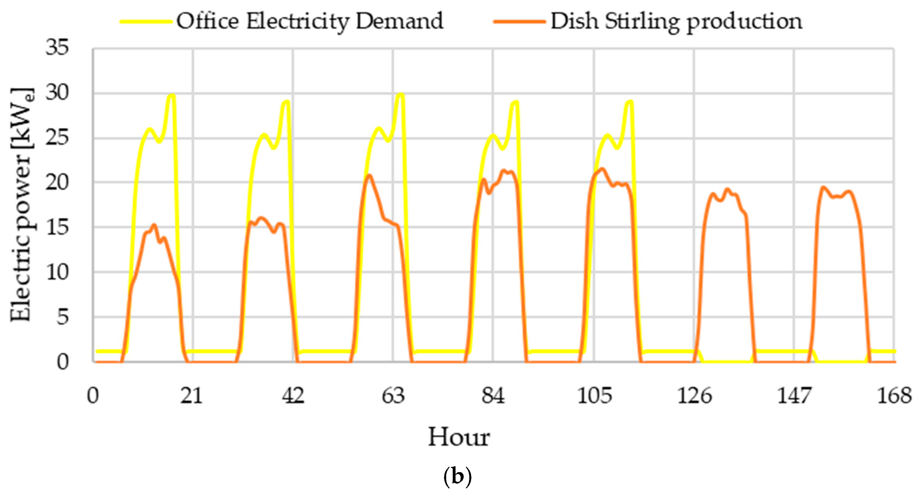
  • focusing on a generic week in August in Figure 9b, the hourly dish-Stirling output power is simultaneous to the office demand, thus indicating that storage should not be installed. Conversely, on non-working days when electricity is not needed, the electricity is sold to the grid.
Annual results for Scenario no. 1-A are shown in Table 3. Since no heat was recovered during the operation, the amount of NG consumed did not vary compared to reference System no.1. Only the amount of electricity purchased from the grid decreased from 63.64 MWhe/y to 18.01 MWhe/y, resulting in 71.7% electricity saving. As a consequence, the same percentage reduction in CO2 emissions is observed.

4.1.2. Results for Scenario 1-B

In this scenario, the dish-Stirling system was operated in cogenerative-mode. In Figure 10a, the profile of the electricity produced by the solar concentrator is plotted along with the aggregated electricity demand profile. In Figure 10b, the electricity produced from the cogenerative dish-Stirling system is compared with the one obtained in electric mode. In Figure 10c, the heat flow recovered is plotted along with the office thermal demand. Note that:
  • as shown in Figure 10a, the electricity produced by the concentrator (green profile) can cover a large share of the entire aggregated electricity demand (yellow profile);
  • as shown in Figure 10b, the profile of the electricity produced from the dish-Stirling system in electricity-mode and the one obtained for Scenario no. 1-B are compared. During the winter, the higher temperature of the cold-side of the Stirling engine, required by the cogenerative asset, leads to a reduction in the electric output power (see dashed black contoured rectangle). From the simulation, it was found that such a reduction is about 15% of the corresponding output power in electricity-mode.
  • as shown in Figure 10c, the heat flow recovered covers at least half of the office thermal demand. Conversely, during the summer, a fraction of the recovered heat flow is used to cover the DHW demand.
Annual results for Scenario no. 1-B are shown in Table 3. Since heat is recovered from the Stirling-engine during winter operation, the amount of NG consumed decreases by about 84.8% compared to the base case and Scenario no. 1-A. Conversely, the amount of electricity produced in Scenario no. 2-A reduces by about 4.6% compared to Scenario no. 1-A due to the lower electric output power of the dish-Stirling system during the winter. However, such a reduction is fully justified by the lower NG consumption achieved. From an environmental viewpoint, a further 31.9% reduction in CO2 emissions is observed passing from Scenario no. 1-A to Scenario no. 1-B.

4.2. Results for Improved System No. 2: Scenario No. 2-A and 2-B

In Scenario no. 2-A, it was assumed that the electricity produced by the dish-Stirling system was used to drive the HP in summer and winter. The yearly profile of the electricity produced by the dish-Stirling system is the same as the one shown in Figure 9a. A reduction of the electricity purchased from the grid is achieved and, as shown in Table 4, it decreases from 71.45 MWhe/y of the base case to 25.15 MWhe/y (almost 65%). The same percentage reduction is observed in the amount of emitted CO2.
In Scenario no. 2-B, it was assumed that the dish-Stirling system operates in a cogenerative-mode. In this scenario, the profile of the electricity and heat produced by the concentrator throughout the year is equal to that shown in Figure 9a,c. In Table 4 the energy and environmental results are shown. Note that, when the heat is recovered, an additional 2.96 MWhe/y of electricity are not purchased from the grid anymore, due to the lower amount of heating demand covered by using the HP. As a consequence, the amount of emitted CO2 decreases from 12,199 kgCO2/y to 11,130 kgCO2/y (−8.8%).
Substantial improvements in both energy and environmental performances are observed passing from the base configuration of System no. 2 to Scenario no. 2-B.

4.3. Economic Results for the Four Analysed Scenarios

The economic feasibility of scenarios 1-A, 1-B, 2-A, and 2-B was assessed using the indicators described in Section 3.3. The results of this analysis are shown in Table 5.
Due to the high investment cost of the dish-Stirling system, it was observed that, with the current investment cost, in the absence of financial support, none of the investigated scenarios achieved a DPBT lower than 25 years.
It is worth considering that the feasibility of the proposed investment improves when the amount of energy saved is economically valued by an ad-hoc feed-in tariff (FIT). To this aim, the last available Italian mechanism supporting the electricity production by renewable sources was assumed as a reference [46]. According to the cited decree, a FIT value was set equal to 0.369 €/kWhe throughout the useful lifetime of the plant. The results of this analysis are shown in Table 5. Under this hypothesis, it was observed that the DPBT is equal to ~19 years for Scenarios 1-A and 2-A, with NPV equal to 35 k€ and 38 k€, respectively. Conversely, when the dish-Stirling system operates in the cogenerative mode for Scenarios 1-B and 2-B, the DBPT decreases to 14–17 years, and NPV is equal to 73 k€ and 45 k€, respectively.
It is of note that the previous indicators were calculated by assuming the same investment cost as the prototype installed in Palermo. In the case of a future full-commercial scale, a reduction in the installed cost is expected and a resulting improvement in the economic viability of the investment will be consequent. In this respect, assuming a 40% reduction of the capital cost (which corresponds to a total installed cost equal to 3645 €/kWp), the DPBT will be lower than 10 years for all the scenarios as shown in Table 5.

4.4. Brief Comparative Analysis of the Key Findings with Other Research

In this section, the key findings of the proposed research are compared with the results of some of the published papers focused on the integration of the dish-Stirling technology into the building sector.
In [31], the authors claimed that the combination of a photovoltaic system and a dish-Stirling system reduced the total energy consumption of a building located in Lebanon by about 68%, decreasing the dependence on the national power grid. Moreover, for the proposed case study in this analysis, the integration of the dish-Stirling allowed a reduction of 65–72% in the amount of electricity purchased from the local power grid for the case of energy plants relying only on electrically-driven systems. These values confirm that, although dependence on other energy sources is inevitable, the integration of this technology could greatly contribute to achieving the self-sufficiency of buildings.
When a cogenerative mode is assumed, 85% percentage variation in the natural gas consumption is observed as well. A higher value of primary energy saving (about 97%) was found in [34], where the authors optimized the configuration of a dish-Stirling collector field, a seasonal geothermal storage, and a water-to-water heat pump system, supplying the heating system of a non-residential building in Palermo. The difference in the previous percentages could be related to the lack of an optimization routine in the present work compared to [34]. However, the achieved value suggests again that the cogenerative asset during the winter could be very promising for reducing energy consumption, also in places mainly characterized by cooling demand. Furthermore, unlike [34], in the present analysis any thermal energy storage was included in the plant layout.
In the end, the comparison of the proposed scenarios for the two energy plants suggests that promising energy-saving and avoided CO2 emissions could be achieved when the energy demands of the served building are met by using both electricity and NG (i.e., 72% for Scenario 1-B). This result is totally in line with the key-findings of [32,34], where the authors considered integrating such technologies to reduce the dependence on natural gas.

5. Conclusions

This paper investigated the energy and environmental benefits achievable by integrating a dish-Stirling system into an energy plant covering the air-conditioning demand of an office building located in Southern Italy. Two different plants were assumed as references, both representative of the typical systems used in this sector. The first one relied on the natural gas boiler for covering the thermal demand and on air-cooled chillers for cooling demand. The second one consisted of a reversible heat pump for covering both heating and cooling demands. For both systems, the benefits of operating the dish-Stirling concentrator in electricity-mode or cogenerative-mode were analyzed. The detailed models adopted for all the main plant components were implemented into the TRNSYS environment and hourly-based simulations were carried out.
Starting from the first systems, it was found that the integration of the dish-Stirling concentrator allows for the reduction of the electricity purchased from 63.64 MWhe/y to 18.01 MWhe/y (about 72%), which also leads to a reduction in CO2 emissions of about 58%. Even better energy performance was achieved by operating the dish-Stirling system in cogenerative-mode during the winter. In this last configuration, it was found that the amount of consumed natural gas decreases by about 85% compared to the base case. However, an increase in the purchased electricity is observed compared to the case of the dish-Stirling system operated in electricity-mode (+4.6%). However, such an increase is more than offset by the reduction in natural gas consumption.
For the second system which included a reversible heat pump, it was found that when the dish-Stirling system operates in electricity-mode, a 65% decrease in the amount of electricity purchased from the grid could be achieved, which passes from 71.45 MWhe/y of the base case to 25.15 MWhe/y. When heat is recovered, an additional 2.96 MWhe/y of electricity is no longer purchased from the grid. Results of this analysis have shown that promising energy saving could be achieved by integrating dish-Stirling technology in conventional energy systems used in the tertiary sector to cover the energy demands. Moreover, the cogenerative asset could be very advantageous and environmentally-friendly when heating demand still relies on fossil fuel consumption. Finally, the economic analysis of the four proposed system scenarios showed that the installation of a dish-Stirling system integrated into a building is only economically viable if financial support is considered. Consequently, there is a clear need to develop appropriate incentive systems to promote the deployment of such systems. Then technological improvements and economies of scale will allow the reduction in total installed cost until it is competitive with that of other currently fully commercialized CSP technologies.

Author Contributions

Conceptualization, investigation, software, validation, methodology, writing original draft, S.G.; conceptualization, investigation, software, methodology, writing original draft, P.C.; software, validation, A.B.; conceptualization, supervision, V.L.B.; conceptualization, supervision, A.P. All authors have read and agreed to the published version of the manuscript.

Funding

This research received no external funding.

Institutional Review Board Statement

Not applicable.

Informed Consent Statement

Not applicable.

Data Availability Statement

Not applicable.

Conflicts of Interest

The authors declare no conflict of interest.

Nomenclature

SymbolsAbbreviations
a 1 first parameter of the Stirling engine mechanical efficiency curve [-]
a 2 second parameter of the Stirling engine mechanical efficiency curve [W]
Aarea [m2]
CFcash flow [€/y]
DPBTDiscounted Payback Time [y]
Eelectric energy [kWh]
E ˙ electric power [W]
hconvective heat transfer coefficient [W/(m2∙K)]
I irradiance [W/m2]
I0total installed cost of the dish-Stirling unit [€]
nuseful lifetime of the plant [y]
nnumber
NPVNet Present Value
Qthermal energy [kWh]
Q ˙ thermal power [W]
rdiscount rate [%]
Rcorrection factor [­]
Ttemperature [°C]
FITfeed-in tariff [€/kWhe]
W ˙ mechanical output power [W]
Greek letters
SymbolsAbbreviations
ε emissivity [-]
η efficiency [­]
μ emission facto [kgCO2/kWh]
σ the Stefan-Boltzmann constant [W/(m2∙K4)]
Subscripts
SymbolsAbbreviations
bbeam component of radiation
clecleanliness
eelectric
Ggeneration
ininlet
nnet effective aperture area of the reflector CSP
pparasitic component
ooptical
outoutlet
SStirling
savsaving
rreceiver
tt-th year of the lifetime of the plant [-]
TTemperature
0referred to the reference
Superscripts
SymbolsAbbreviations
avavoided
aveaverage
Acronyms
SymbolsAbbreviations
CO2Carbon Dioxide
COPCoefficient of Performance
CSPConcentrating Solar Power
DNIDirect Normal Irradiation
GHGGreenhouse Gases
HPHeat Pump
HCHeating Capacity
NGNatural Gas
ODTOutdoor Temperature
PCUPower Conversion Unit
PLRPart Load Ratio
TMYTypical Meteorological Year

References

  1. World Meteorological Organization (WMO). The Global Climate in 2015–2019. Report Published on 2019. Available online: https://library.wmo.int/doc_num.php?explnum_id=9936 (accessed on 7 January 2021).
  2. Berardi, U.; Jafarpur, P. Assessing the impact of climate change on building heating and cooling energy demand in Canada. Renew. Sustain. Energy Rev. 2020, 121, 109681. [Google Scholar] [CrossRef]
  3. Daigle, Q.; O’Brien, P.G. Heat Generated Using Luminescent Solar Concentrators for Building Energy Applications. Energies 2020, 13, 5574. [Google Scholar] [CrossRef]
  4. IEA. Tracking Buildings 2020; IEA: Paris, France, 2020; Available online: https://www.iea.org/reports/tracking-buildings-2020 (accessed on 7 January 2021).
  5. Lund, H. Renewable energy strategies for sustainable development. Energy 2007, 32, 912–919. [Google Scholar] [CrossRef] [Green Version]
  6. Kousksou, T.; Bruel, P.; Jamil, A.; El Rhafiki, T.; Zeraouli, Y. Energy storage: Applications and challenges. Sol. Energy Mater. Sol. Cells 2014, 120, 59–80. [Google Scholar] [CrossRef]
  7. Alharbi, F.; Csala, D. Saudi Arabia’s solar and wind energy penetration: Future performance and requirements. Energies 2020, 13, 588. [Google Scholar] [CrossRef] [Green Version]
  8. Mazzoni, S.; Ooi, S.; Nastasi, B.; Romagnoli, A. Energy storage technologies as techno-economic parameters for master-planning and optimal dispatch in smart multi energy systems. Appl. Energy 2019, 254. [Google Scholar] [CrossRef]
  9. Singh, U.R.; Kumar, A. Review on solar Stirling engine: Development and performance. Therm. Sci. Eng. Prog. 2018, 8, 244–256. [Google Scholar] [CrossRef]
  10. Ampuño, G.; Lata-Garcia, J.; Jurado, F. Evaluation of Energy Efficiency and the Reduction of Atmospheric Emissions by Generating Electricity from a Solar Thermal Power Generation Plant. Energies 2020, 13, 645. [Google Scholar] [CrossRef] [Green Version]
  11. Teske, S.; Leung, J.; Crespo, L.; Bial, M.; Dufour, E.; Richter, C.; Rochon, E. Solar thermal electricity: Global outlook 2016. Report published on 2016 by the European Solar Thermal Electricity Association. Available online: https://https://www.solarpaces.org/solar-thermal-electricity-global-outlook-2016/ (accessed on 10 January 2021).
  12. Lovegrove, K.; Pye, J. Fundamental principles of concentrating solar power (CSP) systems. In Concentrating Solar Power Technology: Principles, Developments and Applications, 2nd ed.; Lovegrove, K., Stein, W., Eds.; Woodhead Publishing: Sawston, UK, 2012; pp. 16–67. ISBN 9781845697693. [Google Scholar]
  13. Coventry, J.; Andraka, C. Dish systems for CSP. Sol. Energy 2017, 152, 140–170. [Google Scholar] [CrossRef]
  14. Poullikkas, A.; Kourtis, G.; Hadjipaschalis, I. Parametric analysis for the installation of solar dish technologies in Mediterranean regions. Renew. Sustain. Energy Rev. 2010, 14, 2772–2783. [Google Scholar] [CrossRef]
  15. Liu, M.; Steven Tay, N.H.; Bell, S.; Belusko, M.; Jacob, R.; Will, G.; Saman, W.; Bruno, F. Review on concentrating solar power plants and new developments in high temperature thermal energy storage technologies. Renew. Sustain. Energy Rev. 2016, 53, 1411–1432. [Google Scholar] [CrossRef]
  16. Abdelhady, S. Performance and cost evaluation of solar dish power plant: Sensitivity analysis of levelized cost of electricity (LCOE) and net present value (NPV). Renew. Energy 2021, 168, 332–342. [Google Scholar] [CrossRef]
  17. Poullikkas, A. Economic analysis of power generation from parabolic trough solar thermal plants for the Mediterranean region—A case study for the island of Cyprus. Renew. Sustain. Energy Rev. 2009, 13, 2474–2484. [Google Scholar] [CrossRef]
  18. Pheng, L.G.; Affandi, R.; Ab Ghani, M.R.; Gan, C.K.; Jano, Z.; Sutikno, T. A review of Parabolic Dish-Stirling Engine System based on concentrating solar power. Telkomnika 2014, 12, 1142. [Google Scholar] [CrossRef] [Green Version]
  19. IRENA. Renewable Power Generation Costs in 2019; International Renewable Energy Agency: Abu Dhabi, Saudi Arabia, 2020; ISBN 978-92-9260-040-2. [Google Scholar]
  20. Islam, M.T.; Huda, N.; Abdullah, A.B.; Saidur, R. A comprehensive review of state-of-the-art concentrating solar power (CSP) technologies: Current status and research trends. Renew. Sustain. Energy Rev. 2018, 91, 987–1018. [Google Scholar] [CrossRef]
  21. Prieto, C.; Fereres, S.; Cabeza, L.F. The Role of Innovation in Industry Product Deployment: Developing Thermal Energy Storage for Concentrated Solar Power. Energies 2020, 13, 2943. [Google Scholar] [CrossRef]
  22. Schiel, W.; Keck, T. Parabolic dish concentrating solar power (CSP) systems. In Concentrating Solar Power Technology; Woodhead Publishing Series in Energy; Lovegrove, K., Stein, W., Eds.; Woodhead Publishing: Sawston, UK, 2012; pp. 284–322. ISBN 978-1-84569-769-3. [Google Scholar]
  23. Mancini, T.; Heller, P.; Butler, B.; Osborn, B.; Schiel, W.; Goldberg, V.; Buck, R.; Diver, R.; Andraka, C.; Moreno, J. Dish-stirling systems: An overview of development and status. J. Sol. Energy Eng. Trans. ASME 2003, 125, 135–151. [Google Scholar] [CrossRef]
  24. Buscemi, A.; Lo Brano, V.; Chiaruzzi, C.; Ciulla, G.; Kalogeri, C. A validated energy model of a solar dish-Stirling system considering the cleanliness of mirrors. Appl. Energy 2020. [Google Scholar] [CrossRef] [Green Version]
  25. Andraka, C.E. Dish Stirling advanced latent storage feasibility. Energy Procedia 2014, 49, 684–693. [Google Scholar] [CrossRef] [Green Version]
  26. Monné, C.; Bravo, Y.; Moreno, F.; Muñoz, M. Analysis of a solar dish-Stirling system with hybridization and thermal storage. Int. J. Energy Environ. Eng. 2014, 5, 1–5. [Google Scholar] [CrossRef] [Green Version]
  27. Abbas, M.; Boumeddane, B.; Said, N.; Chikouche, A. Dish Stirling technology: A 100 MW solar power plant using hydrogen for Algeria. Int. J. Hydrog. Energy 2011, 36, 4305–4314. [Google Scholar] [CrossRef]
  28. Kadri, Y.; Hadj Abdallah, H. Performance evaluation of a stand-alone solar dish Stirling system for power generation suitable for off-grid rural electrification. Energy Convers. Manag. 2016, 129, 140–156. [Google Scholar] [CrossRef]
  29. Al-Dafaie, A.M.A.; Dahdolan, M.E.; Al-Nimr, M.A. Utilizing the heat rejected from a solar dish Stirling engine in potable water production. Sol. Energy 2016, 136, 317–326. [Google Scholar] [CrossRef]
  30. Ferreira, A.C.; Nunes, M.L.; Teixeira, J.C.F.; Martins, L.A.S.B.; Teixeira, S.F.C.F. Thermodynamic and economic optimization of a solar-powered Stirling engine for micro-cogeneration purposes. Energy 2016, 111, 1–17. [Google Scholar] [CrossRef]
  31. El-Bayeh, C.Z.; Alzaareer, K.; Laraki, M.; Brahmi, B.; Panchabikesan, K.; Venturini, W.A.; Eicker, U. A Comparison between PV and Dish Stirling Systems Towards Self-Sufficient Energy Building in Lebanon. In Proceedings of the 2020 5th International Conference on Renewable Energies for Developing Countries (REDEC), Marrakech, Morocco, 29–30 June 2020; pp. 1–6. [Google Scholar]
  32. Moghadam, R.S.; Sayyaadi, H.; Hosseinzade, H. Sizing a solar dish Stirling micro-CHP system for residential application in diverse climatic conditions based on 3E analysis. Energy Convers. Manag. 2013, 75, 348–365. [Google Scholar] [CrossRef]
  33. Khoshbazan, M.; Ahmadi, M.H.; Ming, T.; Tabe Arjmand, J.; Rahimzadeh, M. Thermo-economic analysis and multi-objective optimization of micro-CHP Stirling system for different climates of Iran. Int. J. Low-Carbon Technol. 2018, 13, 388–403. [Google Scholar] [CrossRef]
  34. Guarino, S.; Buscemi, A.; Ciulla, G.; Bonomolo, M.; Lo Brano, V. A dish-stirling solar concentrator coupled to a seasonal thermal energy storage system in the southern mediterranean basin: A cogenerative layout hypothesis. Energy Convers. Manag. 2020, 222, 113228. [Google Scholar] [CrossRef]
  35. Kongtragool, B.; Wongwises, S. Optimum absorber temperature of a once-reflecting full conical concentrator of a low temperature differential Stirling engine. Renew. Energy 2005, 30, 1671–1687. [Google Scholar] [CrossRef]
  36. IMST-Art v. 3.80 [Computer Software]. Developed by IMST-Group, Instituto de Ingeniería Energética Universidad Politécnica de Valencia.
  37. Illán-Gómez, F.; García-Cascales, J.R.; Hidalgo-Mompeán, F.; López-Belchí, A. Experimental assessment of the replacement of a conventional fin-and-tube condenser by a minichannel heat exchanger in an air/water chiller for residential air conditioning. Energy Build. 2017, 144, 104–116. [Google Scholar] [CrossRef]
  38. Pisano, A.; Martínez-Ballester, S.; Corberán, J.M.; Mauro, A.W. Optimal design of a light commercial freezer through the analysis of the combined effects of capillary tube diameter and refrigerant charge on the performance. Int. J. Refrig. 2015, 52, 1–10. [Google Scholar] [CrossRef]
  39. Blanco Castro, J.; Urchueguía, J.F.; Corberán, J.M.; Gonzálvez, J. Optimized design of a heat exchanger for an air-to-water reversible heat pump working with propane (R290) as refrigerant: Modelling analysis and experimental observations. Appl. Therm. Eng. 2005, 25, 2450–2462. [Google Scholar] [CrossRef]
  40. Piacentino, A.; Barbaro, C. A comprehensive tool for efficient design and operation of polygeneration-based energy μgrids serving a cluster of buildings. Part II: Analysis of the applicative potential. Appl. Energy 2013, 111, 1222–1238. [Google Scholar] [CrossRef]
  41. Meteonorm. Global meteorological database--Handbook Part II: Theory, Version 7.1.7.21517. 2015. [Google Scholar]
  42. Suri, M.; Remund, J.; Cebecauer, T.; Hoyer-Click, C.; Dumortier, D.; Huld, T.; Stackhouse, P.; Ineichen, P. Comparison of direct normal irradiation maps for Europe. In Proceedings of the Solar Paces, Berlin, Germany, 15 September 2009. [Google Scholar]
  43. Vahidi Bidhendi, M.; Abbassi, Y. Exploring dynamic operation of a solar dish-stirling engine: Validation and implementation of a novel TRNSYS type. Sustain. Energy Technol. Assess. 2020, 40, 100765. [Google Scholar] [CrossRef]
  44. Klein, S.; Beckman, A.; Mitchell, W.; Duffie, A. TRNSYS 17-A TRansient SYstems Simulation Program; The Solar Energy Laboratory, University of Wisconsin-Madison: Madison WI, USA, 2011. [Google Scholar]
  45. ISPRA Istituto Superiore per la Protezione e la Ricerca Ambientale, (Italian Government Agency). Fattori di Emissione Atmosferica di CO2 e Altri Gas a Effetto Serra Nel Settore Elettrico; 2020; Report published on 2020 (In Italian). Available online: isprambiente.gov.it/it/pubblicazioni/rapporti/fattori-di-emissione-atmosferica-di-gas-a-effetto-serra-nel-settore-elettrico-nazionale-e-nei-principali-paesi-europei.-edizione-2020 (accessed on 14 January 2021).
  46. Ministry of Economic Development (Italy). Decreto Ministeriale 23 giugno 2016: Incentivazione Dell’energia Elettrica Prodotta da Fonti Rinnovabili Diverse Dal Fotovoltaico. 2016. (In Iitalian) [Google Scholar]
Figure 1. Scheme of the energy balance of a dish-Stirling concentrator.
Energies 14 01163 g001
Figure 2. (a) Coefficient of performance and (b) heating capacity of the reversible HP obtained from IMST-Art Simulations in case.
Energies 14 01163 g002
Figure 3. Hourly profiles of the case study: (a) cooling, (b) thermal and (c) electricity demands [40].
Energies 14 01163 g003
Figure 4. The dish-Stirling solar concentrator installed in the test site of Palermo (Italy).
Energies 14 01163 g004
Figure 5. (a) Hourly-frequency histogram (bin of 50 W/m2) of I b and average air temperature for Palermo and (b) monthly electric output energy of the dish-Stirling system.
Energies 14 01163 g005
Figure 6. Schemes of the reference plants assumed for the case study: (a) System no. 1: NG boiler and air-cooled chiller, and (b) System no. 2: reversible heat pump.
Energies 14 01163 g006
Figure 7. Improved scenarios for System no. 1: (a) dish-Stirling system operating in electric-mode, and (b) dish-Stirling system operating in cogenerative-mode.
Energies 14 01163 g007aEnergies 14 01163 g007b
Figure 8. Improved scenarios for System no. 2: (a) dish-Stirling system operating in electric-mode and (b) dish-Stirling system operating in cogenerative-mode.
Energies 14 01163 g008aEnergies 14 01163 g008b
Figure 9. Scenario no. 1-A: (a) profiles of annual electricity demand and dish-Stirling production and (b) weekly profiles of electricity demand and dish-Stirling production.
Energies 14 01163 g009aEnergies 14 01163 g009b
Figure 10. Scenario no. 1-B: (a) profiles of annual electricity demand and dish-Stirling production, (b) electricity profile of dish-Stirling production in electricity mode and the one obtained for cogenerative mode and (c) profile of office thermal demand and heat recovered from dish-Stirling.
Energies 14 01163 g010
Table 1. Main technical features of the air-cooled vapour compression chillers and reversible heat pump.
Reversible Heat Pump
Cooling Capacity 1 56 kW
Heating Capacity 2 57 kW
Air-Cooled Chiller *
Cooling Capacity 1 55 kW
RefrigerantR410AR410A
Condenser Micro-Channels Heat Exchanger
(Number of exchangers: 1; Surface 2.96 m2, Fin pitch 1 mm)
Fin and Tube Heat Exchanger
(Tube diameter 9.2 mm, 3 tube rows, fin density 16 fins per inch)
2 Fan, 1.95 kW each 2 Fan, 1.20 kW
(Air Flowrate per fan 16,388 m3/h)(Air Flowrate per fan 12,362 m3/h)
Metering DeviceElectronic Expansion ValveElectronic Expansion Valve
EvaporatorBrazed Plate Heat ExchangerBrazed Plate Heat Exchanger
Dimension in (mm)
Width = 526, Height = 119, Length = 291
Number of plates 92
Dimension in (mm)
Width = 526, Height = 119, Length = 291
Number of plates 92
1 Pump, 1.0 kW
(Water flow 9.2 m3/h)
1 Pump, 1.0 kW
(Water flow 9.2 m3/h)
Compressor TypeScrollScroll
Swept Volume [cm3/rev]88.32103.5
Compressors Power [kW]9.44 (each)12.4 (each)
Number of Compressors22
Oil Charge [dm3]6.67.2
Refrigerant Charge [kg]1519.9
1 Heat Pump’s cooling capacity refers to the following boundary conditions: variation of the water temperature in the evaporator from 7 to 12 °C, and outdoor air temperature equal to 35 °C (such boundary conditions are also used for the air-cooled chiller). 2 Heat Pump’s heating capacity refers to the following boundary conditions: variation of the water temperature in the condenser from 40 to 45 °C and outdoor air temperature equal to 7 °C.
Table 2. Typical parameters of the dish-Stirling system located in Palermo [24].
ParameterValueUnit
Aperture area of the receiver ( A r )0.0314m2
Average parasitic electric consumption ( E ˙ p ave )1600W
Clean mirrors optical efficiency ( η o )0.85-
Convective heat transfer coefficient of the receiver ( h r )10W/(m2∙K)
Emissivity of the receiver ( ε r )0.88-
Focal length7.45m
Geometric concentration ratio3217-
Max operating pressure of hydrogen200bar
Mirror cleanliness index ( η cle )0.85-
Net aperture area of the dish collector ( A n )106m2
Parameter a 1 in Equation (6)0.475-
Parameter a 2 in Equation (6)3318.66W
Reference temperature ( T o )25°C
Reflectivity of clean mirror ( ρ )0.95-
Temperature of the receiver ( T r )720°C
Table 3. Annual results for System no. 1, Scenario no. 1-A, and Scenario no. 1-B.
System No. 1Scenario No. 1-AScenario No. 1-B
NG consumption [Sm3/y]3970.43970.4601.2
Electricity purchased from the grid [MWhe/y]63.6418.0120.14
Electricity produced by the dish-Stirling [MWhe/y]-46.2944.16
CO2 Emissions [kgCO2/y]38,10715,97610,866
Table 4. Annual results for System no. 2, Scenario no. 2-A, and Scenario no. 2-B.
System No. 2Scenario
No. 2-A
Scenario
No. 2-B
Electricity Purchased from the Grid [MWhe/y]71.4525.1522.95
Electricity Produced by the Dish-Stirling [MWhe/y]-46.3044.16
CO2 Emissions [kgCO2/y]34,65312,19911,130
Table 5. Summary of NPV and DPBT values for the investigated scenarios.
AssumptionsEconomic IndicatorsScenario No. 1-AScenario No. 1-BScenario No. 2-AScenario No. 2-B
(I0, FIT)NPV [€]35,05473,61138,32345,797
DPBT [y]18.614.618.117.2
(Ireduced, FIT)NPV [€]111,445150,002114,713122,187
DPBT [y]9.17.58.98.6
Publisher’s Note: MDPI stays neutral with regard to jurisdictional claims in published maps and institutional affiliations.

