
Operation and Performance Assessment of a Hybrid Solar Heating and Cooling System for Different Configurations and Climatic Conditions


Department of Sustainable Energy Development, Faculty of Energy and Fuels, AGH University of Science and Technology, 30-059 Cracow, Poland
*
Author to whom correspondence should be addressed.
Energies 2021, 14(4), 1142; https://doi.org/10.3390/en14041142
Submission received: 20 January 2021
/
Revised: 12 February 2021
/
Accepted: 16 February 2021
/
Published: 21 February 2021
(This article belongs to the Special Issue Integrated Solar Thermal Systems)
Abstract
:Energy needs of air conditioning systems are constantly growing worldwide, due to climate change and growing standards of buildings. Among the possible systems, solar heating and cooling based on reversible heat pumps and thermally driven chillers are a viable option for ensuring space heating and cooling for different users. The high installation costs are a limit to their diffusion, however, under specific circumstances (climate, type of the building, type of the user, etc.), the investment in this technology can be profitable in a long term. The presented paper describes an energy-economic assessment of a solar heating and cooling system integrating a solar dish concentrator with thermal collectors coupled with a reversible heat pump and an absorption or adsorption chiller. The system integrated with a household building is developed and dynamically simulated in the Transient System Simulation (TRNSYS) environment under different circumstances –adoption of absorption or adsorption chiller, use of auxiliary thermal energy to drive the sorption chillers, and locality. The results show that space cooling demand in Cracow is matched by solar energy, in a range between 49.0 and 97.6%, while for Naples the space cooling demand is provided by solar heat from 46.1 to 99.1% depending on the adopted sorption chiller and or the use of auxiliary heat for a natural gas boiler. The proposed system is not profitable in case Cracow, since a Simple Pay Back period of about 20 years is achieved. Conversely, case of Naples, the same index achieves a value between 8 and 12 years showing that the proposed system may be a viable solution for heating and cooling installation.
1. Introduction
Heating, ventilation, and air conditioning (HVAC) of the building sector has a rate of 30–40% in global energy consumption and a share of approximately 30% of greenhouse gas emissions in the energy-related sector [1,2]. Many efforts are taking place to reduce the negative impact of the operation of such systems, especially in funding the scientific grants for developing advanced renewable energy systems, increasing requirements for energy-efficient buildings, or development of incentive policies for investments in the field of sustainable energy [3,4]. Due to these actions, a positive effect on the European energy sector has been achieved in terms of a 10% decrease in total energy consumption in the last decade, reaching a consumption of 1100 Mtoe in 2017) [1]. Nearly 25% of this energy consumption is related to the European residential sector for HVAC purposes [1].
Constant decreasing of the energy consumption of residential users is possible thanks to the penetration on the market of energy-efficient buildings, like energy plus houses [5], nearly zero-energy buildings (NZEB) [6], refurbishments of old buildings [7] or providing renewable energy sources as a support of buildings energy systems [8]. The most popular energy sources are photovoltaic panels (PV) and photovoltaic-thermal (PVT) collectors [9,10], heat pumps [11], and wind turbines [12,13] For larger-scale consumers, the development of highly efficient hybrid and poly generation systems becomes profitable [14,15].
Globally, there is an increase in demand for air conditioning systems, which is connected with climate change [16]. In this scenario, the most popular air conditioning systems are based on vapor compressor technology. Energy efficiency ratings (EER) of such chillers are relatively high and achieve even over 5 [17], however, the cooling effect is generated with the use of electric energy, which is the most expensive type of supply and it is produced and transmitted with relatively low efficiency. Air conditioning systems are often supplied by geothermal heat sources [18], but the efficiency of heat transfer between the ground-coupling device and the surrounding soil is relatively low which causes a need for a high volume of ground as a thermal sink. Thermally driven chillers powered by heat generated from renewables are an alternative, but their coefficient of performance (COP) is generally less than 1 [19]. However, greenhouse gas emissions caused by the operation of such devices are much lower than the ones produced by conventional systems, and under specific circumstances, their operation may be profitable, which causes the fact of their growing popularity. Examples of applications of the above technologies are presented in the literature description below.
Luna et al. [20] described a study on the coupling of the parabolic trough collector with an air conditioning system with an absorption unit. The studied installation allowed to generate heat up to 6.5 kW at a temperature level at near 105 °C. The highest achieved cooling power was equal to 1.92 kW, with a COP of 0.56. The thermal efficiency of the solar system varied from 8 to 19.8% depending on the conditions. Pinamonti and Baggio [21] presented a coupling of different configurations of solar-assisted heat pump (SAHP) systems with energy storage technologies in order to in order to investigate the factors allowing to decrease the demand, improving self-consumption and system profitability. It was found that, for an insulated building, the maximum energy consumption reduction was of 30% with PV panels and a battery storage, whereas solar collectors, despite the energy consumption reduction of −24% are more economically profitable over the lifetime of the installation. In the study presented in Ref. [22] a single effect absorption chiller system connected with a solar evacuated tube collector field and an auxiliary natural gas burner was dynamically simulated. The best exergy efficiency and solar fraction were achieved for a generator temperature of 97 °C.
Bellos and Tzivanidis [23] presented a model of a trigeneration system for building applications based on parabolic trough collectors, an absorption heat pump and a steam turbine. The small-scale system achieved an electrical, heating and cooling power of 7.16 kW, 9.35 kW and 8.55 kW, respectively for the 80% steam fraction to the turbine. A PVT collector based system for a combined solar heating and cooling application for a residential user was studied by Zarei et al. [24], where water is used to cool the collector and a refrigeration cycle with hybrid ejector-compression is adopted. R600a and R290 were used as refrigerants. The analysis shows that R290 achieves the lowest exergy destruction and the best enhancement of COP with respect to R134a (7.5%).
Most small-scale renewable energy installations are based on solar thermal collectors. Such installations offer a relatively low initial cost and allow to satisfy most of the domestic hot water (DHW) demands. However, for providing higher efficiencies of solar energy systems it is important to maximize solar energy utilization. One of the possible approaches is to provide solar heating and cooling (SHC) installations. SHC systems use the heat produced by solar thermal collectors in order to provide heat for space heating and domestic hot water, and as a supply for a generator in sorption chillers for cooling purposes. In most cases, the availability of solar radiation is correlated with the highest demand for space cooling, which makes solar cooling reasonable from a technical point of view. Buonomano et al. [25] presented a study regarding this technology, describing processes of heat generation by flat plate and concentrating PV-T panels and chill generation by thermally driven chillers. The authors presented a simulation tool that considers the sector’s demand of the user, technology, and region of the world. The localization parameter is crucial for the feasibility of solar systems. In Ref. [26] authors have proven that solar multi-effect chillers are unprofitable in Europe because of low solar fraction, and, as a consequence, low temperature available at the generator of sorption chillers. Such systems need incentives to be competitive with compressor cooling systems.
Wang et al. [27] presented a validated numerical model of a solar cooling system based on a double effect LiBr-H20 chiller and round-shaped parabolic trough solar collector. In a case study of a hotel, the COP of the chiller was below 1.2 and the whole system achieved about 62% of solar energy utilization efficiency. Parametric study showed that it is possible to increase the value of the efficiency up to 69% in the case of a shopping mall or office, which has a more suitable load profile for solar cooling purposes.
The study presented in Ref. [28] provided an optimization algorithm for power modulation in solar thermally driven chillers. The presented methodology allowed to reduce electricity consumption caused by auxiliary devices by 20–60%, depending on weather and operating conditions. The proposed method can be also applied for HVAC systems purposes. An experimental study based on solar heating and cooling system consisted of a 10 kW zeolite-water adsorption chiller and 40 m2 of evacuated tube collectors as a heat source was presented in Ref. [29] Authors proved that in the case of Athene, Greece, it is possible to achieve a COP of the chiller about 0.535. The payback time of the system was about 15 years, however, in countries with dominant heating loads, the payback period lowers up to 7.2 years.
On the basis of the presented literature review, it is possible to note that significant research possibilities are still open in the field of SHC systems. The literature analysis reveals that the studies are mainly focused on hybrid energy systems based on concentrated solar radiation for purposes of large-scale users. Small-scale installations for domestic purposes are not so numerous. Therefore, the aim of this study is to expand the knowledge about micro-scale SHC systems based on heat pumps and on sorption chillers. The proposed system consists of a layout including a solar dish, solar collectors, reversible heat pump, and sorption chiller (absorption or adsorption unit). Heat produced in such a system is used for heating purposes in winter months and as a supply of the sorption chiller generator in summer months, and during the whole year for the production of DHW. The system is based on solar collectors connected with a dish concentrator.
The system was investigated using a dynamic simulation tool, namely Transient System Simulation (TRNSYS) software, by developing a model based on build-in software components and user-defined models previously validated against experimental and/or technical data. In particular, the model of the concentrating solar collector was based on a validated model of the parabolic dish solar concentrator previously developed by the authors, moreover, the present layout has been based on a solar cooling system integrating such concentrator investigated in a previous paper of the authors [30]. The novelty of the presented installation is connected with few technical points-preheating the working medium before reaching the high-temperature heat exchanger located in the focus of the concentrator, possible use of auxiliary heater before sorption chiller used for air-conditioning purposes, and connecting the solar-heating system with a reversible heat pump. In this paper, the proposed hybrid SHC system configuration is investigated comprehensively by means of dynamic simulation for the first time in literature. The paper presents a dynamic simulation of the mentioned system, which allows the described installation to be adapted to any other country conditions.
2. Materials and Methods
2.1. Description of the Installation
The proposed solar heating and cooling system was based on a small scale installation integrating two serial connected flat plate solar thermal collectors, a 180 cm diameter parabolic bowl, covered with reflective foil, and a 120 cm diameter parabolic mirror (Figure 1). The concentrator was equipped with a double-axis tracking system with an algorithm based on light sensors. In this configuration, the working medium, preheated in collectors, is supplied to an aluminum-made hemispherical high-temperature receiver with a milled internal canal in order to increase its temperature. The whole system was controlled and managed by a WAGO 750–881 Programmable Logic Controller (PLC) system with connected analog and digital input/output modules. The system allowed to measure oil temperature in 8 points of the circuit, working medium pressure, flowrate, and solar radiation (diffuse, direct-horizontal, direct-tracker surface, direct-collector surface, total). The system allowed to control the flowrate of the thermal oil by controlling a circulation pump. A detailed description of the laboratory stand has been provided Ref. [30]. The working medium used in the installation was thermal oil ITERM 6 MB [31].
The numerical model of the solar concentrator was presented and validated in a previous paper of the authors [30]. The model was developed with the use of TRNSYS 17 software and was based on the utilization of type 539 and mentioned model of the concentrator. The arrangement of the model was made by adding the pipes connecting the devices in order to replicate in the simulation environment the real installation. The validation of the model was based on the basis of the temperatures and thermal energy generated by the devices. Data taken from the simulations were compared with experimental data, especially, total solar radiation, diffused solar radiation, mass flowrate and temperature levels. The validated model was the basis of the development of the proposed SHC system.
2.2. Layout of the System and Operation Strategy
The investigated system is based on the integration of flat-plate collectors, concentrator, and adsorption chiller in a traditional DHW, space heating, and cooling system adopting a natural gas boiler and a reversible heat pump system for space conditioning. Solar thermal collectors and the concentrator are used for providing DHW all year long and space heating in the heating season by means of a reversible heat pump with water-to-water loops, while the adsorption chiller is used in the cooling season for providing air conditioning with the produced solar heat.
In the proposed arrangement of solar devices, the concentrator is used in order to increase the temperature of the working medium boosting up the thermal energy production of the system. Thus, the concentrator operation allows one to reach more frequently the desired temperature inside the tank in order to supply both heat pump and thermally driven chiller in winter and summer, respectively, and this, as a consequence, allows one to use more frequently the produced solar heat.
In winter, the dry cooler system is used as a heat source when the solar thermal energy is scarce, while in summer it is used to reject heat from the adsorption chiller and the heat pump operating as a chiller. An auxiliary heating boiler is used to match the DHW thermal demand in case of low solar radiation and when the produced heat by the solar devices and stored in the thermal storage is not sufficient to supply the adsorption chiller. Moreover, the reversible heat pump is also adopted in summer as an additional backup air conditioning device in case of low-temperature level in the thermal energy storage. The layout of the system has been shown in Figure 2.
The hybrid SHC system consisted of seven loops designed to manage properly the thermal energy flows:
- Hot Water, HW: water-glycol mixture heated by the solar thermal collectors and the concentrator, stored in the thermal storage and the domestic hot water tank and used as a heat source for the evaporator of the reversible heat pump during winter and the hot side of the adsorption chiller during summer.
- Chilled Water, CHW: chilled water produced by the evaporator of the adsorption chiller, supplying the fan-coil system in cooling season;
- Cooling Water, CW: water-glycol mixture circulating from the dry cooler to the condenser of the adsorption chiller and the reversible heat pump in summer, or to the evaporator of the heat pump in winter;
- Heating-Cooling Water, HCW: hot or cold water supplying the fan-coil system for space cooling purposes;
- Domestic Hot Water, DHW: sanitary water used by in the household;
- Aqueduct Water, AW: mains water used to produce DHW;
- Gas Boiler Water, GBF: water heated up in the gas boiler for purposes of DHW preparation.
The main components of the system are the following:
- Solar collectors, SC: flat plate selective solar collectors used to produce thermal energy from the total solar radiation;
- Concentrator, CONC: a parabolic dish concentrator with receiver equipped with a two-axis tracking system;
- Thermal storage tank, TK1: an insulated tank with thermal stratification used to accumulate thermal energy generated by the solar loop;
- Domestic hot water tank, TK2: a tank integrating two internal heat exchangers dedicated to the heating of water by the produced solar thermal energy and by the auxiliary heating device;
- Natural gas boiler, GB: a natural gas-fired boiler used to heat TK2 and to heat up the hot water in order to run the adsorption chiller;
- Sorption chiller, ACH: a thermally driven chiller consisting of a LiBr single-stage absorption chiller of a zeolite matrix-based adsorption chiller, used to produce chilled water;
- Reversible heat pump, RHP: a vapor compression reversible unit used to produce heating water for space cooling and chilled water for space cooling when the adsorption chiller operation is not possible;
- Dry cooler, DC: an air to fluid heat exchanger used to provide thermal energy for the heat pump in winter in case of low thermal energy stored in TK1, or used to dissipate the thermal energy rejected by the adsorption and vapor compression chiller when operating;
- Hydraulic separator, HS: double inlet-outlet vessel used to separate the primary and the secondary heating system;
- Fan coils, FC: water to indoor air heat exchangers used to provide heat and cool to the rooms of the building.
The main system components were connected to each other by means of pipes, diverters, mixers, and pumps, while the control and management model was developed using virtual temperature sensors and several controllers. The logic of the system operation has been reported below.
The working medium in the solar part of the HW loop is pumped by P1, activated when the solar radiation reaches 10 W/m2 [32]. Solar radiation is transformed in thermal energy with the use of both solar collectors and the concentrator, whose operation causes the increase of the water-glycol mixture temperature. The supply of HW to solar collectors and concentrator is controlled by double by-pass connections (M1/D1 and M2/D2), used to avoid the possibility of cooling of the working medium during circulating within the devices. The control system activates by-pass connections in case of a situation when the temperature at the SC or CONC outlet is lower than the inlet temperature.
During the heating season, the solar loop supplies HW to TK1 and TK2 in order to provide thermal energy for space conditioning and DHW production. TK1 tank has valves D3 and M3, which allow to manage the supply of HW. In the situation when HW temperature is higher than TK1 top temperature by 2 °C, the control system allows to supply HW to TK1. In a scenario when the HW temperature is lower than the TK1 top temperature, the by-pass D3/M3 is activated. This same control strategy is adopted for TK2 by means of M4/D4 in order to prevent the cooling of the bottom part of the tank. In this case, the water temperature in the proximity of internal heat exchanger of TK2 is used for the control strategy. In winter, the heating operation of the top part of TK1 is performed when its temperature drops to 15 °C, while it is stopped when the temperature increases to 25 °C. It is worth noticing that the TK1 temperature may decrease below the fixed set point due to the variation of weather conditions. From TK1, HW is supplied to the evaporator side of the reversible heat pump, which operates in order to keep a proper temperature for the FC system. In particular, RHP operates in order to keep the temperature at the outlet of HS between 40 and 42 °C. The set point temperature for the heated water by RHP was set to 40 °C. Moreover, in order to achieve the best possible performance of RHP, outside air may be supplied to DC for RHP operation. In fact, TK1 stops to supply heat to RHP when the outside air temperature increases by 2 °C above TK1 top temperature, while this operation stops once the air temperature decreases to the one inside TK1.
DHW is provided to the user at constant temperature. In the situation when TK2 top temperature exceeds 45 °C, mains water is mixed with the tank water in order to provide the required DHW temperature which is equal to 45 °C. In case of an insufficient amount of solar radiation, which is connected to TK2 top temperature below 55 °C, the control system activates gas boiler GB, which heats the water at the top part of TK2 to the set point of 65 °C. The deadband of 10 °C allows one to limit the number of activation of GB to heat TK2.
During the cooling season, the heating of TK1 by the solar loop is performed to keep its top temperature between a level allowing to run the sorption chiller: for the absorption unit the temperature range is 80–90 °C, while for the adsorption chiller it is 60–70 °C.
The activation of the absorption unit occurs once the temperature rises to 80 °C, and the deactivation is performed when the temperature drops to 75 °C. For the adsorption chiller, the required temperature level allowing to activate the unit is set to 58 °C, while the one that deactivates the chiller is fixed to 53 °C. It is worth notice that the selected temperatures for the activation and deactivation of both thermally driven chillers are compatible with the operation specification of small-scale devices provided by manufacturers [33,34].
During the operation of ACH, GB may supply auxiliary heat to drive the sorption chillers. In the case of absorption chiller, when the inlet temperature of the generator of ACH decreases to 77 °C, GB heats HW to 80 °C until the TK1 top temperature increases to 79 °C. In the scenario where the adsorption chiller is integrated into the system layout, when TK1 temperature drops to 55 °C, GB is turned on to heat HW to 60 °C until TK1 top temperature rises to 57 °C. In the operation of the space cooling system, the chilled water temperature is maintained at the level of 7 °C (by ACH and RHP), allowing the proper operation of the fan-coil system.
The control system turns off the sorption chiller ACH when the generator inlet temperature decreases below the allowed minimum threshold, then the electric chiller ECH is switched on. Furthermore, during the operation of the ACH, when the outlet temperature of the load side of the HS exceeds 12 °C, in case of a high space cooling demand of the user or a decrease of ACH chilling power, the auxiliary chilling equipment is activated. In the mentioned case, ACH is switched off and ECH is used to reduce HS outlet temperature to 10 °C.
The space conditioning system ensures a temperature inside the building rooms in a range of 20–22 °C and 24–26 °C [11] during the space heating and cooling season, respectively. When the temperature inside the building is on a sufficient level, the FC system is turned off. Finally, cooling water CW, supplied by P3 to the dry cooler is used in order to dissipate the thermal energy rejected by the ECH condenser or ACH cooling circuit.
2.3. Model of the System
The system under investigation was modeled and simulated using Transient System Simulation (TRNSYS) software, which is a tool capable to simulate the transient operation of conventional, renewable, and new concept energy systems. The main features of this environment consist of a vast library of validated components, the possibility of implement user-defined components, and flexibility in developing the layout of the systems as well as their control and operation strategy.
In the frame of this paper is not possible to present each model of the adopted components for reasons of brevity, thus only the detailed description of the energy and economic analysis model is presented, since the other models are available in the TRNSYS software documentation containing the mathematical structure of components [35] or are available in the literature. Nevertheless, some information about the adopted models (types) are reported below.
The flat-plate solar collector is modelled taking into account the thermal performance of a theoretical collector. In particular, the Hottel-Whillier steady-state model [36] is used for evaluating the thermal performance, while the overall thermal loss coefficient of the collector per unit area is determined on the basis of Ref. [37].
The model of the concentrator and the absorption chiller have been presented in Ref. [30]. For the concentrator, the working medium temperature at the outlet of the receiver To was calculated with the following equation:
where Tin is the inlet temperature, Q is the amount of heat transferred to the working fluid, m is the mass flow and cp is the specific heat. Q is given by the formula:
where: A is the receiver surface (aperture), FR is the overall collector heat removal efficiency factor, GT is the intensity of direct solar radiation at the receiver surface, U is the overall thermal loss coefficient of the collector per area of the unit, T is the average working medium temperature inside the receiver and Ta is the ambient temperature. FR coefficient is given by:
where fp is the total efficiency of the receiver. U coefficient was calculated taking into account the radiative and convective heat losses according the following equations:
where: hr is the radiative loss coefficient, hk is the convective loss coefficient [38] σ is the Stefan-Boltzmann constant, εp is the receiver surface emissivity, Tm is the average medium temperature inside the receiver, Ts is effective sky temperature and v is the wind velocity.
The model of the absorption chiller was based on mass and enthalpy balance equations from the point of view of water-LiBr mixture and only LiBr in the different point of heat exchangers of the device (generator, absorber, evaporator and condenser). For the LiBr in the weak and strong solution concentrations were assumed from Ref. [34]. The thermal power of the i-th Qi heat exchangers was calculated as:
where min and mout represent the mass flow rate at the inlet and outlet, hin and hout represent the enthalpy at the inlet and outlet, respectively. The COP of the absorption unit was calculated with the following equation:
where Qeva and Qgen is the thermal power of evaporator and generator, respectively.
The efficiencies η of heat exchangers in all loops of the absorption chiller were given by the following formula:
where UHE it the overall heat-transfer coefficient of heat exchanger, AHE is the total heat transfer surface, m is the flow rate of the given working fluid and cp is its specific heat.
The adsorption chiller component was based on manufacturer data (Invensor LTC 10 E PLUS) [34] and a model comprehensively described in a previous paper of the authors [32]. The model uses user-supplied data files with cooling capacity and COP taken from manufacturer data as a function of different inlet temperatures of hot, chilled and cooling parts of the device and liquid mass flow rates.
The model for summer operation of the fan-coils is reported in Ref. [15]. The model was based on correction factors taking into account for fluid mass flow rate, inlet fluid and air dry/wet temperature, and air flow rate.
The list of the adopted components has been provided in Table 1.
Energy and Economic Model
In order to assess the performance of the novel hybrid system from the energy and economic point of view, a Reference System (RS) was adopter for the comparison with the proposed system (PS). RS consisted of an air-to-water reversible heat pump for space heating and cooling and a natural gas boiler used for DHW production. The analysis was performed assuming that both systems must provide an equal quantity of final energy to the user, in the form of space conditioning and DHW.
The consumption of primary energy of PS and RS was calculated at a boiler system efficiency of 0.85% [15] and an averaged Polish electric network efficiency of 0.33 [39]. In the calculation, the following energy flows were taken into account for RS:
- energy consumed in the form of natural gas for the production of DHW;
- electrical energy used by RHP operating with air as a heat source for space heating (seasonal COP = 2.5);
- electrical energy used by RHP operating for space cooling (seasonal COP = 3.5);
- while for PS:
- energy consumed by GB for the integration of the heat needed to produce DHW and HW auxiliary heating for sorption chiller operation under low temperature available at the generator;
- electrical energy used by RHP operating with the solar loop and air as a heat source for space heating;
- electrical energy used by RHP operating as an auxiliary unit for space cooling.
Under these assumptions the following equations were adopted to evaluate the Primary Energy (PE) of both RS and PS and the Primary Energy Saving ratio (PESr) of PS:
where PERS is the primary energy consumption of reference system, Eth,GB,DHW,RS is the energy consumed for purposes of domestic hot water preparation for RS, ηGB is the efficiency of the gas boiler, Eth,heating is the energy consumed for heating purposes, COPRHP,heating,RS is the coefficient of performance of the reversible heat pump in heating mode for RS, ηel is electric grid efficiency, Eth,cooling is the energy consumed for purposes of cooling, COPRHP,cooling,RS is the coefficient of performance of the reversible heat pump in cooling mode for RS.
where PEPS is the primary energy consumption of PS, Eth,GB,DHW,PS is the energy consumed for purposes of domestic hot water preparation for PS, Eth,GB,ACH,PS is the energy consumed for purposes of cooling with the use of sorption chiller for PS, Eel,RHP,heating,PS is the electric energy for purposes of heating with the use of reversible heat pump for PS and Eel,RHP,cooling,PS is the electric energy for purposes of cooling with the use of reversible heat pump for PS.
where PESR is the primary energy saving ratio.
The economic parameters of PS were evaluated by calculating the investment costs of the mentioned system taken from manufacturers and operating costs of both RS and PS, according to the methodology available in literature [40]. Parabolic dish concentrator with a double-axis tracking system costs was assumed to 118 €/m2 and 825 €, respectively [30]. Solar thermal collectors cost was 150 €/m2 and for the absorption and adsorption chiller units was 300 and 500 €/kW, respectively [39]. The cost of other components, like control system, pumps, etc., was included in the total costs of PS and the maintenance costs of PS and RS were ware assumed to be the same, allowing to neglect the effect of maintenance on the economic results.
To calculate the operating costs of both systems, the natural gas and electrical energy price were taken from the Eurostat data [41], thus were set to 0.0425 and 0.1475 €/kWh, respectively. Costs of operation of both RS and PS systems (Cop) and the savings (ΔCop) were calculated based on Equations (3) and (4).
where Cop,RS is the cost of operation of the RS, cng is the cost of natural gas, Eel,RHP,heating,RS is the electric energy used for purposes of heating with the use of reversible heat pump, RS, Eel,RHP,cooling,RS is the electric energy used for purposes of cooling with the use of reversible heat pump, RS and cel are the costs of electric energy.
where Cop,PS are the costs of operation, PS, and Eel,auxiliaries,PS is the electric energy used for purposes of auxiliary elements, proposed system.
where ΔCop are the savings caused by implementation of the proposed system
The simple Pay Back period (SPB), defined as the ratio between the cost of the proposed system and the savings, was calculated to assess the economic results of the hybrid system.
2.4. Case Study
The case study adopted to investigate the system energy and economic performance consisted of a one floor single family household, with an attic, and a sloped roof (Figure 3). The model of the building structure has been adopted in other papers of the authors [30]. In the present case, the thermal load of the building were calculated within the developed model assuming Typical Meteorological Year (TMY) climatic conditions with the adoption of Meteonorm weather data of Cracow, Southern Poland. The building geometrical structure has been reported in Figure 3. The ground floor area consisted of one room of 50 m2 and two rooms of 25 m2, while the attic had a useful area of 75 m2. The floor height was 2.70 m and the slope of the roof was 30°. The building exposition with respect to the south-north direction has been set as shown in Figure 3. The building envelope elements, as walls, roof, and floor, were modeled setting several layers for each component simulating the structure of a realistic building envelope. The information about building envelope components have been reported in Table 2 in terms of thermal transmittance and structure.
The building hydronic air conditioning system consisted of one fan-coil for each zone of the building, operating from 15 November to 31 March and from 1 May to 15 October during the heating and cooling season, respectively. Regarding the daily operation, air heating was set for the whole day, while air cooling was assumed to work from 8:00 am to 10:00 pm. In the thermal model of the building, realistic thermal load and loads were implemented (Table 3). The DHW demand was set to 60 L/person/day with a realistic profile during the day. The hourly space heating and cooling demand for the case study building is shown in Figure 4.
The case study in terms of system configuration was completed assuming several design and operational parameters of all components. The main parameters have been listed in Table 4.
In order to determine the values of such parameters, manufacturer data were used and an iterative sizing/design procedure was performed, allowing to achieve a satisfactory system configuration from the point of view of energy generation, dynamic operation, and capability to cover the thermal demand of the building users. It is worth noticing that for the solar collecting devices the size was selected taking into account their thermal energy production in order to meet a part of the user demand. Thus, the aperture area of SC and CONC are higher than the ones of the units present in the experimental installation. The selection of different areas was possible because the models of the components are validated, thus the reliability of the simulations is independent of the selected configuration of each solar device.
3. Results and Discussion
In order to perform the simulation and the investigation of the system, the simulation time was set to one year (from 0 to 8760 h) with a timestep of 0.05 h, allowing to achieve a satisfactory time resolution in terms of the dynamic behavior of the system. The simulation was carried out for the layout with an adsorption (ADS) and absorption (ABS) chiller with and without the operation of GB in order to provide auxiliary heat to such devices.
In particular, the dynamic trends of the system variables were analyzed for the entire system operation along the year, nevertheless, for sake of brevity, only the trends of temperature and powers highlighting the operation of the system with ADS and GB providing auxiliary heat for a typical winter and summer day have been reported in the following. The same configuration of ADS and GB was selected to show the operation of the system during the year with weekly results. The yearly energy and economic results of the system were discussed for all the configurations of thermally driven chillers al GB operation for the base case study consisting of Cracow locality, and for a different locality consisting of Naples, Southern Italy. For the simulation of the second locality, Eurostat data regarding energy prices were used, as for the first one.
3.1. Daily Analysis for Winter Operation
The system operation in terms of temperatures and power trends, calculated with dynamic simulation, has been presented for the day of January 25th, occurring from 600th to 624th of the year. The temperatures of the working fluids at the outlet of the main components and the ambient air temperature have been reported in Figure 5.
In the night hours, the temperatures at the outlet of SC and CONC decrease due to the lack of solar radiation and the occurrence of thermal losses to the environment. In the same way, the temperature at the top of TK1 decreases during the first morning hours due to a short activation of the tank in order to supply the source side of RHP. This occurs because the air temperature in the same period drops and equals the temperature of the tank, thus DC, which provides thermal energy to RHP, is turned off and the P2 starts to pump HW to RHP. This operation occurs only for about 30 min since the air temperature starts to be 2 °C higher than the one of the water inside the TK1 top part. This condition is also present after 8:00 am. It is interesting to note that after TK1 thermal energy supply to RHP, the top temperature of TK1 starts to slightly increase due to the internal heat exchange inside the stratified tank. In fact, the temperature at the middle part of the tank is higher than the top one.
According to the implemented control strategy, SC and CONC start to operate after about 8:00 am, due to the increase of solar radiation above 10 W/m2. However, after that time TK1 has not reached an adequate temperature to provide heat to RHP, thus only after 10:00, am when the tank temperature overcomes the air one, solar heat is used as a source for the evaporator of RHP. The heating operation of the TK1 tank continues to about 3:00 pm, when the tank achieves the temperature of 25 °C, and after that the thermal energy generated by both SC and CONS is transferred by the internal heat exchanger to TK2 in order to heat DHW. The condition of a thermally loaded TK1 tank allows to operate RHP only with solar thermal energy to the end of the day with no activation of DC.
During the winter operation day, RHP stabilizes the temperature of the heated water to about 40 °C, and only some oscillations are present due to the increase of the temperature returning by the FC heating system of the user, that is caused by the reduction of the thermal demand for space heating. In such a case, the heat pump is activated and deactivated in order to keep the inlet temperature to FC below the maximum set point of 42 °C.
The operation of the system in terms of thermal powers of the main system components for the same selected day are reported in Figure 6. In this figure, it clearly shown the activation and deactivation of the system components. The thermal energy production of SC and CONS is present during the central hours of the day (8 h), and here the different magnitude of the energy production between the devices, due to the collection of different components of the solar radiation and different aperture area, can be noticed. In the first part of the day, RHP operates at almost constant load, due to the slight variation of the air temperature, and during such time it is for the most of the time supplied by DC. Only in two moments TK1 supplies thermal energy to RHP, as pointed out also by the temperature trends. The constant operation of RHP ends after 9:00 am when the space heating demand decreases due to the increase of air temperature and the presence of solar radiation. After such a moment the thermal power supplied by the load side of RHP is a function of the operation of the FC system, where the heating units operate to keep the air temperature of the rooms between 20 and 22 °C.
3.2. Daily Analysis for Summer Operation
The typical operation of the system during the cooling season has been presented for the day of August 2nd, occurring from 5112th to 5136th of the year. The temperatures of the loops at the outlet of the main components have been reported in Figure 7.
After about 6:00 am, the activation of the solar loop occurs, and SC and CONC outlet temperatures start to increase due to the increase of solar radiation. However, during the first operation hours the thermal energy produced is only supplied to TK2 in order to heat DHW, since only after 10:00 the temperature at the outlet of CONC rises above the one present at the top of TK1, allowing one to increase the temperature of the thermal storage up to a maximum of 65 °C. The heating of TK1 by SC and CONC continues to about 4:30 pm, when the solar loop temperature starts to decrease.
During the night hours, TK1 temperature decreases, thus when the space cooling system is activated, the activation of GB in order to provide auxiliary heat to ADS is required. In fact, the tank temperature remained above the limit determining the deactivation of the adsorption chiller (53 °C), this GB operation was possible. The activation of GB increase also TK1 temperature, due to heated fluid by GB returning from ADS. It is worth noting that the activation of GB is repeated again during the morning hours, due to the decrease of TK1 temperature caused by the thermal demand of ADS for space cooling.
Furthermore, the temperature trends also show that the thermally driven chiller is sufficient to provide space cooling during the selected day, indeed the temperature of TK1 oscillates on the activation range of ADS and the chiller is capable to provide chilled water at the fixed set point (7 °C). In the same way, on the side of the FC system, the returning temperature oscillations are also limited, due to the relatively small variation of the cooling demand.
The operation of the system in terms of thermal powers of the main system components for the summer day are reported in Figure 8. In this figure, the activation and deactivation of GB and ADS are clearly pointed out. As previously mentioned, during the first morning hours GB provides auxiliary heat to ADS in order to allow its operation without turning on RHP in cooling mode. In addition, during the day the ADS cooling power, and this the thermal power supplied by TK1, increases significantly. This occurs because additional cooling must be performed for all the rooms of the building in order to keep the air temperature between 24 and 26 °C. Moreover, the dynamic trends show that the thermal energy supplied by GB to run ADS when TK1 temperature decreases below 55 °C is relatively small.
3.3. Weekly Analysis of the System Operation
The thermal energy of the main system components on weekly basis have been shown in Figure 9 and Figure 10. The thermal energy produced by SC and CONC undertakes an oscillatory trend depending on the solar irradiance and thermal load of the system. In detail, the solar thermal energy production is lower during winter as compared to the summer period, and this affects the amount of thermal energy used for DHW in the cold months, since the majority of the energy goes to TK1, and this involves the activation of GB for DHW production. On the other hand, during the central weeks of the year, the supply of solar heat to TK2 oscillates stably, highlighting that the DHW demand is almost entirely met by solar energy. This is due to an oversized solar system with respect to the sole DHW demand, indeed during the period when space conditioning is not needed (heating and cooling), the thermal energy production of SC drops. The lower is the thermal demand of the user, the higher is the operating temperature of the solar loop, and thus higher are the thermal losses. Among the solar devices, flat plate collectors are the ones that are more sensitive to the operation temperature, thus the effect is higher compared to the concentrating unit. Moreover, due to the high-temperature operation also the summer heat production levels are limited, achieving values comparable to the ones present and the end and beginning of the heating season.
The activation of GB in order to supply heat to ADS in summer is frequent in some weeks when the solar energy production is higher. In fact, the higher is the energy yield, the higher is the space cooling demand. The weekly trend also highlights that the operation of RHP is rarely needed during the summer period since the majority of the space cooling demand is match by the solar-powered adsorption chiller. This is partly due to the relatively small space cooling demand of the user compared to the heating one. For this reason, the activation of RHP as an auxiliary device for cooling purposes is rarely needed.
The thermal efficiency of SC and CONC and the COP of ADS and RHP have been reported in Figure 11.
SC field achieves a relatively better thermal performance during the winter with respect to summer and mid-season weeks, and this is due to the lower operation temperature of HW. In fact, during such a period the solar collector works with a relatively small temperature, limiting the thermal losses. Therefore, the variation of SC efficiency is significant, ranging between 0.159 and 0.705. Conversely, apart from few weeks in the mid-season period, the efficiency of CONC is stable, varying from 0.738 to 0.817. The variation of COP of ADS is relatively small (0.514–0.619), and, as expected, the highest values are achieved for the weeks with higher insolation. This result is due to the implemented control strategy on the ADS generator supply temperature, which is kept in the required range by the supply of heat by TK1 and GB. Furthermore, the COP of RHP during winter oscillates between 2.24 and 4.59, while during the cooling period it ranges from 4.16 and 6.387.
3.4. Yearly Results
The annual analysis of the system energy and economic performance was carried outperforming a one-year integration period within the simulation. As mentioned the results were carried out for two locations (Cracow and Naples) under four thermally driven/auxiliary heating configurations. Main thermal and electrical energies in the system and the energy and economic indexes of the system for Cracow and Naples localities have been reported in Table 5 and Table 6, respectively.
The results outline that solar energy produced by SC is about 2–3 times higher with respect to CONC for the selected localities. This is due to the different aperture areas of the devices and the different availability of the solar direct radiation. However, the energy yield of CONC is not marginal due to the better thermal performance of the concentrator with respect to the solar collectors. It is important to note that the effect of the adoption of different thermally driven chillers on the solar thermal energy production is negligible since the temperature variations in the solar loop due to the type of chiller adopted are limited. However, the type of chiller unit affects the heat provided by TK1 during summer. The higher activation temperature of ABS with respect to ADS decreases the heat available for the activation of the thermally driven unit.
The result shows that DHW consumption of the user is covered mainly by the solar system for all the selected localities, indeed solar energy contributes to the production of DHW between 55.4 and 58.2% for Cracow, and from 86.3 and 89.4% for Naples. Moreover, it is worth noting that the solar thermal energy supplied by TK1 to the source side of RHP in the case of Cracow is about 2.5 times higher with respect to Naples, despite the different solar energy availability. This is due to a higher space heating demand of the Polish locality compared to the Italian one.
The space cooling demand is matched in almost the major part by solar energy compared to the electrical chiller in Cracow, ranging between 49.0 and 97.6%, while for Naples the space cooling demand is provided by solar heat from 46.1 to 99.1%.
The thermal efficiency of SC is lower for Naples compared to Krakow, due to higher solar energy availability determining an increase of solar loop operating temperature, which implies higher thermal losses, especially in the summer period. For the same reason, the efficiency of CONC is lower for Naples, due to the higher operation temperature of the receiver. Nevertheless, the efficiency variation for Naples is limited, since it is confined to range from 5.9 to 6.6%.
The results also point out that the adoption of GB as an auxiliary device to drive the thermally driven chiller in case of scarce solar radiation has a limited effect on the COP of the unit. This is achieved because the temperature of the hot fluid is similar to the one provided by the solar loop under normal operation and because in such a temperature range both devices are not significantly affected by the driving temperature. Moreover, a similar result is outlined looking locality at the effect of the locality, since it scarcely affects the COP of both ADS and ABS. This condition is achieved on the basis of the temperature control strategy and a relatively small mean generator variation between Cracow and Naples.
From the point of view of primary energy saving, the variation of PESr for all the system configurations in Cracow is from 0.261 and 0.297, revealing that the effect of the type of chiller and the adoption of an auxiliary device is scarce. Nevertheless, it must be noticed that the use of GB reduces PESr of about 0.03. For Naples, PESr varies between 0.480 and 0.664, and the effect of GB on PESr is higher since is in the range of 0.133 and 0.146. The result is due to the magnitude of space cooling energy demand, being higher for Naples compared to Cracow. Higher is the cooling demand, higher is the influence of the energy source for the production of space cooling.
Looking at the economic results, it is evident that the proposed system is not feasible in case Cracow, since high investment cost is not connected with adequate savings that may be achieved. Indeed, despite a high heating demand, the system not achieves in the winter period a substantial increase of the performance in providing space heating compared to the reference system. This economic result is also due to relatively small cooling demand and energy prices (natural gas and electricity). Moreover, the adoption of a more costly thermally driven chiller, as well as the adoption of GB as an auxiliary device, affects negatively the economics of the system.
Finally, in the case of Naples, SPB values are two times lower compared to Cracow, which is achieved since for this locality the space cooling demand, electrical energy, and natural gas prices are higher. Under these conditions, the proposed system may be a possible and valid solution as an alternative to conventional heating and cooling systems based only on reversible heat pumps.
4. Conclusions
In the paper, a comprehensive investigation of the operation and energy, and economic performance of a novel and hybrid solar heating and cooling system is presented. The study is focused on a system consisting of a flat-plate solar collector, solar concentrator, thermal storage, reversible water-to-water heat pump and thermally driven chiller (absorption and adsorption unit) used to provide space conditioning in winter and summer and to produce domestic hot water during the whole year. The system uses also air as a heat source or heat sink, by means of a dry cooler, for the reversible heat pump during winter and to reject thermal energy related to space conditioning in summer, respectively. The system is examined using dynamic simulation carried out with TRNSYS software and assuming a reference system consisting of a conventional reversible heat pump for air conditioning and a natural gas boiler for domestic hot water heating. The latter one is assumed to be operating also in the proposed system for auxiliary production of domestic hot water and producing auxiliary heat for the thermally activated chiller. The system is applied to a residential user, consisting of a household with five inhabitants under the weather conditions of Cracow, Southern Poland. In order to assess the system performance for different conditions, Naples, Southern Italy, is selected for comparison.
The adoption of adsorption or absorption unit as chiller along with the possibility to use or not the natural gas boiler for providing auxiliary heat to such chillers are investigated. In particular, the system dynamic behavior is analyzed on daily basis for the configuration with adsorption chiller and natural gas boiler as an auxiliary device for a representative winter and summer day. A weekly time scale is adopted to investigate the system performance along the yearly operation period, while yearly energy and economic parameters are calculated to evaluate the global performance for different system configurations under Cracow and Naples conditions. The analysis reveals that:
- -
- in the winter period and night hours, after a thermal energy by the storage tank to the reversible heat pump, the top temperature of the tank starts to slightly increase due to the internal heat exchange inside the stratified tank. Moreover, the condition of a thermally loaded TK1 tank allows one to operate the reversible heat pump only with solar thermal energy until the end of the day without using external air as a heat source for the device;
- -
- in the summer period, when the space cooling system is activated, the activation of the axiality boiler in order to provide auxiliary heat to ADS is required;
- -
- the activation of the gas boiler in order to supply heat to the adsorption chiller in summer is frequent in some weeks when the solar energy production is higher. In fact, the higher is the energy yield, the higher is the space cooling demand. This operation characteristics is found also in Ref. [42], where the auxiliary boiler must be activated during the hottest weeks of summer when the cooling load is high. The weekly trend also highlights that the operation of the reversible heat pump is rarely needed during the summer period, since the majority of the space cooling demand is matched by the solar-powered adsorption chiller;
- -
- the weekly variation of solar collectors efficiency is significant, ranging between 0.159 and 0.705. Conversely, apart from few weeks in the mid-season period, the efficiency of the concentrator is stable, varying from 0.738 to 0.817. The variation of the Coefficient of Performance of the adsorption chiller is relatively small (0.514–0.619), and the highest values are achieved for the weeks with higher insolation. The achieved performance of the adsorption unit is similar to the ones reported in literature [43]. This is due to the adoption of a commercially available unit and ensuring a temperature operation range allowed by the manufacturer;
- -
- the effect of the adoption of different thermally driven chillers on the yearly solar thermal energy production is negligible since the temperature variations in the solar loop due to the type of chiller adopted are limited. However, higher activation temperature of the absorption chiller with respect to the adsorption unit decreases the heat available for the activation of the thermally driven unit;
- -
- the space cooling demand is matched in almost the major part by solar energy compared to the electrical chiller in Cracow, ranging between 49.0 and 97.6%, while for Naples the space cooling demand is provided by solar heat from 46.1 to 99.1%. The solar fraction for Cracow is coherent with the one achievable in Berlin [44], which has similar weather conditions to the selected Polish locality. On the other hand, also for Naples the achieved solar cooling system performance is similar to literature data [45], pointing out that the system performance is intrinsically related to the weather conditions of the selected locality;
- -
- the variation of the Primary Energy Saving ratio for all the system configurations in Cracow is from 0.261 and 0.297, revealing that the effect of the type of chiller and the adoption of an auxiliary device is scarce. Whereas, for Naples, the same ratio varies between 0.480 and 0.664, and the effect of the operation of the natural has on the energy-saving is higher;
- -
- the proposed system is not profitable in case Cracow, since a Simple Pay Back period of about 20 years is achieved. Conversely, case of Naples, the same index achieves a value between 8 and 12 years showing that the proposed system may be a viable solution for heating and cooling installation. These results find confirmation in a previous paper of the authors [30], although in the present paper a different solar cooling installation and the solar heating option are considered. This shows that for the proposed system the adoption of only cooling or both solar heating and cooling operation modes does not affects significantly the economic profitability of the system, independently from the considered location.
Author Contributions
Conceptualization, R.F. and M.Ż.; methodology, R.F.; software, R.F.; validation, R.F. and M.Ż.; formal analysis, R.F. and M.Ż.; investigation, R.F.; resources, R.F. and M.Ż.; data curation, R.F.; writing—original draft preparation, R.F. and M.Ż.; writing—review and editing, R.F.; visualization, R.F.; supervision, R.F. All authors have read and agreed to the published version of the manuscript.
Funding
Part of this research was funded by the Polish Ministry of Higher Education on the basis of the decision number 0086/DIA/2019/48.
Acknowledgments
This work was carried out under Subvention and Subvention for Young Scientists, Faculty of Energy and Fuels, AGH University of Science and Technology, Krakow, Poland. The authors acknowledge the use of the infrastructure of the Center of Energy, AGH UST in Krakow.
Conflicts of Interest
The authors declare no conflict of interest.
References
- IEA—International Energy Agency. Available online: https://www.iea.org/ (accessed on 3 May 2020).
- Nejat, P.; Jomehzadeh, F.; Taheri, M.M.; Gohari, M.; Majid, M.Z.A. A global review of energy consumption, CO2 emissions and policy in the residential sector (with an overview of the top ten CO2 emitting countries). Renew. Sustain. Energy Rev. 2015, 43, 843–862. [Google Scholar] [CrossRef]
- Aquila, G.; Pamplona, E.D.O.; De Queiroz, A.R.; Junior, P.R.; Fonseca, M.N. An overview of incentive policies for the expansion of renewable energy generation in electricity power systems and the Brazilian experience. Renew. Sustain. Energy Rev. 2017, 70, 1090–1098. [Google Scholar] [CrossRef]
- CEER. Status Review of Renewable Support Schemes in Europe for 2016 and 2017 Public Report; Council of European Energy Regulators ASBL: Brussels, Belgium, 2018. [Google Scholar]
- Rodriguez-Ubinas, E.; Montero, C.; Porteros, M.; Vega, S.; Navarro, I.; Castillo-Cagigal, M.; Matallanas, E.; Gutiérrez, A. Passive design strategies and performance of Net Energy Plus Houses. Energy Build. 2014, 83, 10–22. [Google Scholar] [CrossRef] [Green Version]
- Fedorczak-Cisak, M.; Furtak, M.; Hayduk, G.; Kwasnowski, P. Energy Analysis and Cost Efficiency of External Partitions in Low Energy Buildings. IOP Conf. Series: Mater. Sci. Eng. 2019, 471, 112095. [Google Scholar] [CrossRef]
- Šijanec, M.; Andraž, Z.; Stegnar, R.G.; Summers, C.; Hulme, J.; 06 -Bre, P.; Dascalaki, E.; Balaras, C.; Droutsa, P.; Kontoyiannidis, S.; et al. Energy Performance Indicator Tracking Schemes for the Continuous Optimisation of Refurbishment Processes in European Housing Stocks Monitor Progress Towards Climate Targets in European Housing Stocks Main Results of the EPISCOPE Project-Final Project Report-(Deliverable D1.2); Institut Wohnen und Umwelt GmbH: Darmstadt, Germany, 2016; ISBN 978-3-941140-56-1. [Google Scholar]
- Calise, F.; Figaj, R.D.; Vanoli, L. Energy and Economic Analysis of Energy Savings Measures in a Swimming Pool Centre by Means of Dynamic Simulations. Energies 2018, 11, 2182. [Google Scholar] [CrossRef] [Green Version]
- Żołądek, M.; Sornek, K.; Papis, K.; Figaj, R.; Filipowicz, M. Experimental and Numerical Analysis of Photovoltaics System Improvements in Urban Area. Civ. Environ. Eng. Rep. 2018, 28, 13–24. [Google Scholar] [CrossRef] [Green Version]
- Kasaeian, A.; Nouri, G.; Ranjbaran, P.; Wen, D. Solar collectors and photovoltaics as combined heat and power systems: A critical review. Energy Convers. Manag. 2018, 156, 688–705. [Google Scholar] [CrossRef] [Green Version]
- Calise, F.; D’Accadia, M.D.; Figaj, R.D.; Vanoli, L. Thermoeconomic optimization of a solar-assisted heat pump based on transient simulations and computer Design of Experiments. Energy Convers. Manag. 2016, 125, 166–184. [Google Scholar] [CrossRef]
- Filipowicz, M.; Żołądek, M.; Goryl, W.; Sornek, K. Urban ecological energy generation on the example of elevation wind turbines located at Center of Energy AGH. E3S Web Conf. 2018, 49, 00023. [Google Scholar] [CrossRef] [Green Version]
- Li, H.; Campana, P.E.; Tan, Y.; Yan, J. Feasibility study about using a stand-alone wind power driven heat pump for space heating. Appl. Energy 2018, 228, 1486–1498. [Google Scholar] [CrossRef]
- Figaj, R.; Żołądek, M.; Goryl, W. Dynamic Simulation and Energy Economic Analysis of a Household Hybrid Ground-Solar-Wind System Using TRNSYS Software. Energies 2020, 13, 3523. [Google Scholar] [CrossRef]
- Calise, F.; Figaj, R.D.; Vanoli, L. A novel polygeneration system integrating photovoltaic/thermal collectors, solar assisted heat pump, adsorption chiller and electrical energy storage: Dynamic and energy-economic analysis. Energy Convers. Manag. 2017, 149, 798–814. [Google Scholar] [CrossRef]
- The Future of Air Conditioning World Demand & Warming Temperature Increases. Available online: https://www.enerdata.net/publications/executive-briefing/the-future-air-conditioning-global-demand.html (accessed on 18 August 2020).
- Kadam, S.T.; Hassan, I.; Rahman, M.A.; Papadopoulos, A.I.; Seferlis, P. Review on Modeling of Vapor Compression Chillers: District Cooling Perspective. Int. J. Air-Cond. Refrig. 2020, 28, 2030003. [Google Scholar] [CrossRef]
- Gan, G. Dynamic interactions between the ground heat exchanger and environments in earth–air tunnel ventilation of buildings. Energy Build. 2014, 85, 12–22. [Google Scholar] [CrossRef] [Green Version]
- Critoph, R.; Zhong, Y. Review of trends in solid sorption refrigeration and heat pumping technology. Proc. Inst. Mech. Eng. Part E J. Process. Mech. Eng. 2005, 219, 285–300. [Google Scholar] [CrossRef]
- Luna, Y.R.G.; Franco, W.R.G.; Carrasco, U.D.; Domínguez, R.J.R.; García, J.C.J. Integration of the Experimental Results of a Parabolic Trough Collector (PTC) Solar Plant to an Absorption Air-Conditioning System. Appl. Sci. 2018, 8, 2163. [Google Scholar] [CrossRef] [Green Version]
- Pinamonti, M.; Baggio, P. Energy and economic optimization of solar-assisted heat pump systems with storage technologies for heating and cooling in residential buildings. Renew. Energy 2020, 157, 90–99. [Google Scholar] [CrossRef]
- Rad, E.A.; Davoodi, V. Thermo-economic evaluation of a hybrid solar-gas driven and air-cooled absorption chiller integrated with hot water production by a transient modeling. Renew. Energy 2021, 163, 1253–1264. [Google Scholar] [CrossRef]
- Bellos, E.; Tzivanidis, C. Energetic and exergetic evaluation of a novel trigeneration system driven by parabolic trough solar collectors. Therm. Sci. Eng. Prog. 2018, 6, 41–47. [Google Scholar] [CrossRef]
- Zarei, A.; Liravi, M.; Rabiee, M.B.; Ghodrat, M. A Novel, eco-friendly combined solar cooling and heating system, powered by hybrid Photovoltaic thermal (PVT) collector for domestic application. Energy Convers. Manag. 2020, 222, 113198. [Google Scholar] [CrossRef]
- Buonomano, A.; Calise, F.; Palombo, A. Solar heating and cooling systems by absorption and adsorption chillers driven by stationary and concentrating photovoltaic/thermal solar collectors: Modelling and simulation. Renew. Sustain. Energy Rev. 2018, 82, 1874–1908. [Google Scholar] [CrossRef]
- Shirazi, A.; Taylor, R.A.; Morrison, G.L.; White, S.D. Solar-powered absorption chillers: A comprehensive and critical review. Energy Convers. Manag. 2018, 171, 59–81. [Google Scholar] [CrossRef]
- Wang, J.; Yan, R.; Wang, Z.; Zhang, X.; Shi, G. Thermal Performance Analysis of an Absorption Cooling System Based on Parabolic Trough Solar Collectors. Energies 2018, 11, 2679. [Google Scholar] [CrossRef] [Green Version]
- Dalibard, A.; Gürlich, D.; Schneider, D.; Eicker, U. Control Optimization of Solar Thermally Driven Chillers. Energies 2016, 9, 864. [Google Scholar] [CrossRef] [Green Version]
- Roumpedakis, T.C.; Vasta, S.; Sapienza, A.; Kallis, G.; Karellas, S.; Wittstadt, U.; Tanne, M.; Harborth, N.; Sonnenfeld, U. Performance Results of a Solar Adsorption Cooling and Heating Unit. Energies 2020, 13, 1630. [Google Scholar] [CrossRef] [Green Version]
- Figaj, R.; Szubel, M.; Przenzak, E.; Filipowicz, M. Feasibility of a small-scale hybrid dish/flat-plate solar collector system as a heat source for an absorption cooling unit. Appl. Therm. Eng. 2019, 163, 114399. [Google Scholar] [CrossRef]
- ORLEN OIL—ITERM 6 MB Thermal Oil Data Sheet. Available online: https://www.orlenoil.pl/EN/OurOffer/Products/Pages/produkt.aspx?produkt=ITERM_6_MB.aspx (accessed on 8 April 2020).
- Calise, F.; D’Accadia, M.D.; Figaj, R.D.; Vanoli, L. A novel solar-assisted heat pump driven by photovoltaic/thermal collectors: Dynamic simulation and thermoeconomic optimization. Energy 2016, 95, 346–366. [Google Scholar] [CrossRef]
- Yazaki Energy Systems, Inc. Available online: https://www.yazakienergy.com/waterfiredperformance.htm (accessed on 12 February 2021).
- Invensor LTC 10 e plus—InvenSor. Available online: http://invensor.com/en/products/invensor-ltc-10-e-plus/ (accessed on 20 January 2021).
- Klein, S.A. TRNSYS 18: A Transient System Simulation Program, Solar Energy Laboratory; University of Wisconsin: Madison, WI, USA, 2017. [Google Scholar]
- Florschuetz, L. Extension of the Hottel-Whillier model to the analysis of combined photovoltaic/thermal flat plate collectors. Sol. Energy 1979, 22, 361–366. [Google Scholar] [CrossRef]
- Klein, S. Calculation of flat-plate collector loss coefficients. Sol. Energy 1975, 17, 79–80. [Google Scholar] [CrossRef]
- American Society of Heating, Refrigerating and Air Conditioning Engineers, Inc. Handbook, Fundamental; American Society of Heating: Atlanta, GA, USA, 1985. [Google Scholar]
- ABB. Poland—Energy Efficiency Report; ABB: Warsaw, Poland, 2011. [Google Scholar]
- Figaj, R.; Sornek, K.; Podlasek, S.; Żołądek, M. Operation and Sensitivity Analysis of a Micro-Scale Hybrid Trigeneration System Integrating a Water Steam Cycle and Wind Turbine under Different Reference Scenarios. Energies 2020, 13, 5697. [Google Scholar] [CrossRef]
- Eurostat—European Comission. Available online: https://ec.europa.eu/eurostat/ (accessed on 9 April 2020).
- Calise, F. High temperature solar heating and cooling systems for different Mediterranean climates: Dynamic simulation and economic assessment. Appl. Therm. Eng. 2012, 32, 108–124. [Google Scholar] [CrossRef]
- Alahmer, A.; Ajib, S.; Wang, X. Comprehensive strategies for performance improvement of adsorption air conditioning systems: A review. Renew. Sustain. Energy Rev. 2019, 99, 138–158. [Google Scholar] [CrossRef]
- Palomba, V.; Wittstadt, U.; Bonanno, A.; Tanne, M.; Harborth, N.; Vasta, S. Components and design guidelines for solar cooling systems: The experience of ZEOSOL. Renew. Energy 2019, 141, 678–692. [Google Scholar] [CrossRef]
- Buonomano, A.; Calise, F.; D’Accadia, M.D.; Ferruzzi, G.; Frascogna, S.; Palombo, A.; Russo, R.; Scarpellino, M. Experimental analysis and dynamic simulation of a novel high-temperature solar cooling system. Energy Convers. Manag. 2016, 109, 19–39. [Google Scholar] [CrossRef]
Figure 1.
Parabolic dish concentrator with two focusing elements: bowl lined with reflective foil and parabolic mirror.
Figure 1.
Parabolic dish concentrator with two focusing elements: bowl lined with reflective foil and parabolic mirror.
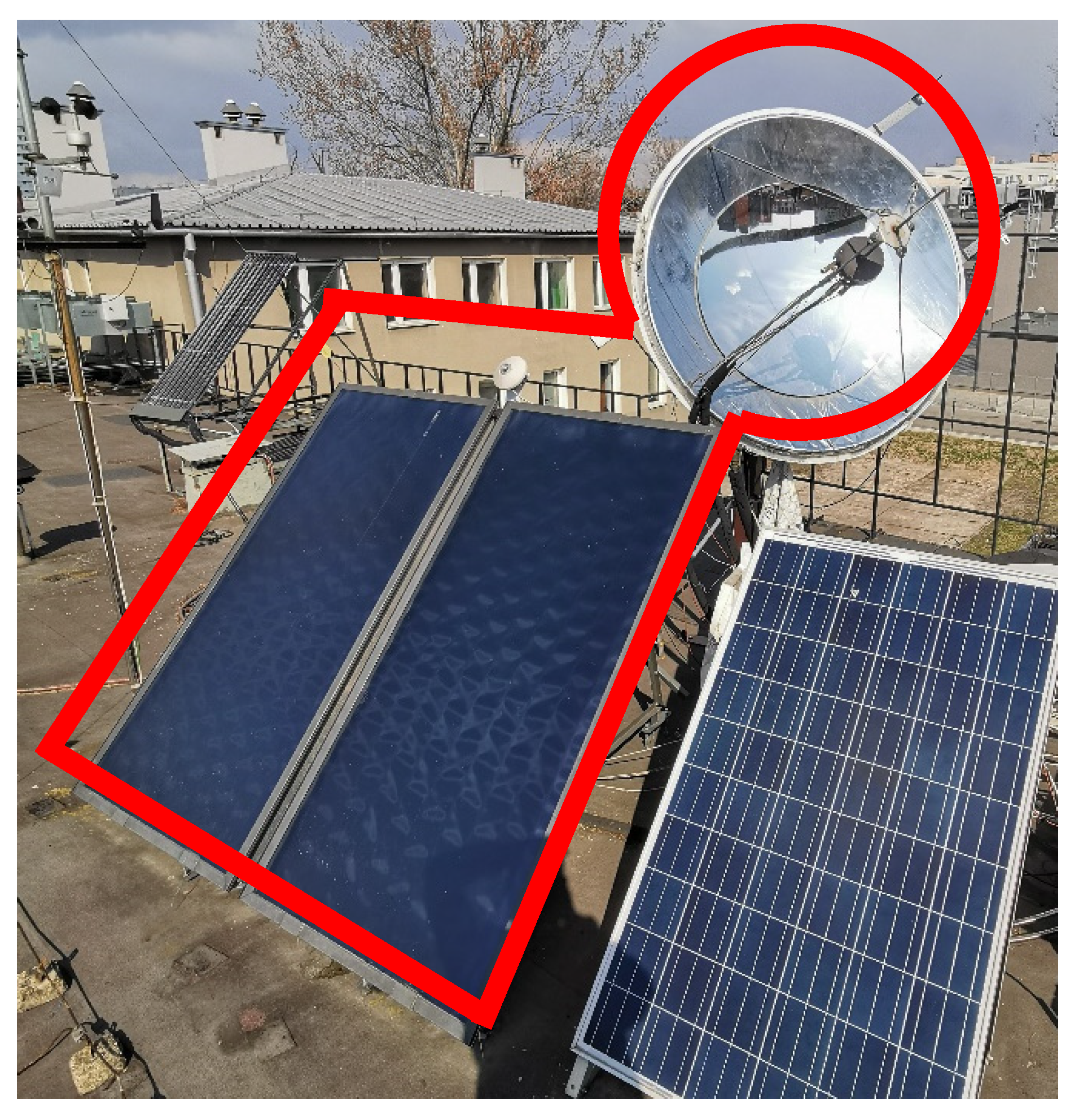
Figure 2.
Layout of the analyzed hybrid SHC system.

Figure 3.
Building structure: (a) outside and (b) inside.

Figure 4.
Thermal power demand for space heating and cooling of the building.

Figure 5.
Temperatures of the working fluids at the outlet of the main components and the ambient air temperature, winter day.
Figure 5.
Temperatures of the working fluids at the outlet of the main components and the ambient air temperature, winter day.

Figure 6.
Thermal powers of the main system components, winter day.

Figure 7.
Temperatures at the outlet of the main components, summer day.

Figure 8.
Thermal powers of the main system components, summer day.

Figure 9.
Thermal energy flows of SC, CONC, TK1, TK2, and GB for ADS, weekly analysis.

Figure 10.
Thermal energy flows of RHP, ADS, and DC, weekly analysis.

Figure 11.
Thermal efficiency of SC and CONC and the COP of ADS and RHP, weekly analysis.


Table 1.
TRNSYS components adopted to develop the simulation model of the system.
| Component | Type | Component | Type |
|---|---|---|---|
| SC | 73 | pipes | 31 |
| TK1 | 4c | building | 56 |
| TK2 | 340 | weather data reader | 109 |
| Adsorption chiller | 909 | on/off controller with hysteresis | 2 |
| RHP | 927 | winter summer scheduler | 515 |
| GB | 751 | schedulers | 14h, 516 |
| HS | 60c | diverter and mixers | 11, 647, 649 |
| DC | 511 | data integrator | 24 |
| FC, summer operation | 508a | data plotter | 65 |
| P, fixed flow pumps | 3 | data printer | 25c |
Table 2.
Building envelop elements thermal transmittance and structure.
| Building Envelop Element | Transmittance [W/(m2K)] | Description and Structure |
|---|---|---|
| External window | 1.10 | frame to window ratio: 0.2 |
| External wall | 0.40 | external plaster: 2.0 cm, insulation: 7.0 cm, brick: 20.0 cm, internal plaster: 1.0 cm |
| Adjacent wall | 2.20 | internal plaster: 1.0 cm, brick: 17.0 cm, internal plaster: 1.0 cm |
| Ceiling | 1.58 | wood parquet: 1.5 cm, concrete: 15.0 cm, brick: 15.0 cm, internal plaster: 2.0 cm |
| Roof | 0.32 | roof sheet: 0.1 cm, insulation: 10.0 cm, brick: 10 cm, internal plaster: 1.0 cm |
| Ground floor | 0.37 | wood parquet: 1.5 cm, concrete: 5.0 cm, insulation: 7.0 cm, foundation slab: 30.0 cm, |
Table 3.
Internal thermal loads of the building.
| Load | Description |
|---|---|
| Person activity | 5 persons, sensible heat 75 W, latent heat 75 W |
| Electric equipment | 3.3 W/m2 |
| Lights | 5.0 W/m2 |
| Fresh air infiltration | Fresh air changes, 0.25 Vol/h |
Table 4.
Parameters of the main components of the hybrid system.
| Parameter | Value | Unit | Parameter | Value | Unit |
|---|---|---|---|---|---|
| SC, Area | 15 | m2 | TK1, thermal loss coefficient | 0.694 | W/m2/K |
| SC, slope | 30 | ° | TK1, height | 1.3 | m |
| SC, absorber emittance | 0.1 | - | TK2, volume | 250 | L |
| SC, absorptance of absorber | 0.95 | - | TK2, thermal loss coefficient | 0.694 | W/m2/K |
| SC, loss coefficient | 0.833 | W/m2/K | TK1, height | 1.2 | m |
| CONC, dish area | 5 | m2 | Absorption chiller, cooling capacity | 7 | kW |
| CONC, receiver area | 0.03 | m2 | Adsorption chiller, cooling capacity | 7 | kW |
| CONC, receiver absorptance | 0.9 | - | Adsorption chiller, nominal COP | 0.72 | - |
| CONC, emittance | 0.8 | 0 | P2, flowrate | 1680 | kg/h |
| HW, specific heat | 3.66 | kJ/kg/K | P3, flowrate | 1580 | kg/h |
| HW, density | 1036 | kg/m3 | P4, flowrate | 700 | kg/h |
| P1, flowrate per SC area | 100 | kg/h/m2 | P5, flowrate | 1050 | kg/h |
| TK1, volume per SC area | 50 | L/m2 | P6, flowrate | 2400 | kg/h |
Table 5.
Yearly results for Cracow location.
| Parameter | ADS + GB | ADS | ABS + GB | ABS | Unit |
|---|---|---|---|---|---|
| ISC | 1.79 × 10⁴ | 1.79 × 10⁴ | 1.79 × 10⁴ | 1.79 × 10⁴ | kWh/year |
| ICONC | 3.00 × 10³ | 3.00 × 10³ | 3.00 × 10³ | 3.00 × 10³ | kWh/year |
| Eth,SC | 6.89 × 10³ | 6.93 × 10³ | 6.38 × 10³ | 6.42 × 10³ | kWh/year |
| Eth,CONC | 2.23 × 10³ | 2.23 × 10³ | 2.24 × 10³ | 2.24 × 10³ | kWh/year |
| Eth,winter,TK1 | 2.79 × 10³ | 2.79 × 10³ | 2.79 × 10³ | 2.79 × 10³ | kWh/year |
| Eth,summer,TK1 | 2.92 × 10³ | 2.99 × 10³ | 2.19 × 10³ | 2.26 × 10³ | kWh/year |
| Eth,TK2,SC + CONC | 2.38 × 10³ | 2.37 × 10³ | 2.50 × 10³ | 2.51 × 10³ | kWh/year |
| Eth,TK2,GB | 1.92 × 10³ | 1.93 × 10³ | 1.79 × 10³ | 1.80 × 10³ | kWh/year |
| Eth,ADS,GB | 8.45 × 10² | - | 7.78 × 10² | - | kWh/year |
| Eth,source,ACH | 3.20 × 10³ | 2.44 × 10³ | 2.15 × 10³ | 1.47 × 10³ | kWh/year |
| Eth,load,ACH | 1.88 × 10³ | 1.42 × 10³ | 1.59 × 10³ | 1.09 × 10³ | kWh/year |
| Eth,source,winter,RHP | 6.40 × 10³ | 6.39 × 10³ | 6.39 × 10³ | 6.40 × 10³ | kWh/year |
| Eth,load,winter,RHP | 9.72 × 10³ | 9.72 × 10³ | 9.71 × 10³ | 9.72 × 10³ | kWh/year |
| Eth,source,summer,RHP | 5.58 × 101 | 7.13 × 10² | 7.65 × 10² | 1.39 × 10³ | kWh/year |
| Eth,load,summer,RHP | 4.56 × 101 | 5.86 × 10² | 6.29 × 10² | 1.14 × 10³ | kWh/year |
| Eth,winter,DC | 3.30 × 10³ | 3.29 × 10³ | 3.30 × 10³ | 3.29 × 10³ | kWh/year |
| Eth,summer,ACH,DC | 4.45 × 10³ | 3.38 × 10³ | 3.22 × 10³ | 2.19 × 10³ | kWh/year |
| Eth,summer,RHP,DC | 5.37 × 101 | 7.05 × 10² | 7.48 × 10² | 1.38 × 10³ | kWh/year |
| Eth,winter,HS | 9.61 × 10³ | 9.61 × 10³ | 9.61 × 10³ | 9.61 × 10³ | kWh/year |
| Eth,summer,HS | 2.10 × 10³ | 2.10 × 10³ | 2.12 × 10³ | 2.12 × 10³ | kWh/year |
| Eel,winter,RHP | 3.32 × 10³ | 3.32 × 10³ | 3.32 × 10³ | 3.32 × 10³ | kWh/year |
| Eel,summer,RHP | 1.02 × 101 | 1.28 × 10² | 1.36 × 10² | 2.49 × 10² | kWh/year |
| Eel,auxiliaries | 3.98 × 10² | 3.87 × 10² | 3.68 × 10² | 3.55 × 10² | kWh/year |
| ηSC | 0.386 | 0.388 | 0.357 | 0.360 | - |
| ηCONC | 0.745 | 0.743 | 0.746 | 0.747 | - |
| COPACH | 0.587 | 0.581 | 0.739 | 0.740 | - |
| COPwinter,RHP | 2.926 | 2.925 | 2.925 | 2.926 | - |
| COPsummer,RHP | 4.467 | 4.591 | 4.619 | 4.555 | - |
| PEPS | 1.45 × 10⁴ | 1.39 × 10⁴ | 1.46 × 10⁴ | 1.40 × 10⁴ | kWh/year |
| PESr | 0.263 | 0.297 | 0.261 | 0.291 | - |
| ΔCOP | 2.99 × 10² | 3.23 × 10² | 2.91 × 10² | 3.12 × 10² | €/year |
| SPB | 24.0 | 22.2 | 19.8 | 18.4 | years |
Table 6.
Yearly results for Naples location.
| Parameter | ADS + GB | ADS | ABS + GB | ABS | Unit |
|---|---|---|---|---|---|
| ISC | 2.60 × 10⁴ | 2.60 × 10⁴ | 2.60 × 10⁴ | 2.60 × 10⁴ | kWh/year |
| ICONC | 5.86 × 10³ | 5.86 × 10³ | 5.86 × 10³ | 5.86 × 10³ | kWh/year |
| Eth,SC | 9.12 × 10³ | 9.12 × 10³ | 8.13 × 10³ | 8.22 × 10³ | kWh/year |
| Eth,CONC | 4.10 × 10³ | 4.10 × 10³ | 4.09 × 10³ | 4.10 × 10³ | kWh/year |
| Eth,winter,TK1 | 1.10 × 10³ | 1.10 × 10³ | 1.09 × 10³ | 1.09 × 10³ | kWh/year |
| Eth,summer,TK1 | 6.67 × 10³ | 6.72 × 10³ | 5.40 × 10³ | 5.51 × 10³ | kWh/year |
| Eth,TK2,SC + CONC | 3.61 × 10³ | 3.60 × 10³ | 3.73 × 10³ | 3.73 × 10³ | kWh/year |
| Eth,TK2,GB | 5.69 × 10² | 5.71 × 10² | 4.42 × 10² | 4.43 × 10² | kWh/year |
| Eth,ADS,GB | 3.24 × 10³ | - | 2.91 × 10³ | - | kWh/year |
| Eth,source,ACH | 9.28 × 10³ | 6.15 × 10³ | 7.39 × 10³ | 4.64 × 10³ | kWh/year |
| Eth,load,ACH | 5.93 × 10³ | 3.85 × 10³ | 5.51 × 10³ | 3.46 × 10³ | kWh/year |
| Eth,source,winter,RHP | 1.35 × 10³ | 1.35 × 10³ | 1.35 × 10³ | 1.35 × 10³ | kWh/year |
| Eth,load,winter,RHP | 1.79 × 10³ | 1.79 × 10³ | 1.79 × 10³ | 1.79 × 10³ | kWh/year |
| Eth,source,summer,RHP | 6.32 × 101 | 3.31 × 10³ | 2.44 × 10³ | 5.00 × 10³ | kWh/year |
| Eth,load,summer,RHP | 5.16 × 101 | 2.68 × 10³ | 1.98 × 10³ | 4.04 × 10³ | kWh/year |
| Eth,winter,DC | 1.75 × 10² | 1.76 × 10² | 1.75 × 10² | 1.76 × 10² | kWh/year |
| Eth,summer,ACH,DC | 1.33 × 10⁴ | 8.72 × 10³ | 1.10 × 10⁴ | 6.89 × 10³ | kWh/year |
| Eth,summer,RHP,DC | 6.22 × 101 | 3.29 × 10³ | 2.41 × 10³ | 4.98 × 10³ | kWh/year |
| Eth,winter,HS | 1.66 × 10³ | 1.66 × 10³ | 1.66 × 10³ | 1.66 × 10³ | kWh/year |
| Eth,summer,HS | 6.77 × 10³ | 7.00 × 10³ | 7.40 × 10³ | 7.40 × 10³ | kWh/year |
| Eel,winter,RHP | 4.40 × 10² | 4.40 × 10² | 4.41 × 10² | 4.40 × 10² | kWh/year |
| Eel,summer,RHP | 1.16 × 101 | 6.27 × 10² | 4.63 × 10² | 9.62 × 10² | kWh/year |
| Eel,auxiliaries | 2.71 × 10² | 2.69 × 10² | 2.68 × 10² | 2.68 × 10² | kWh/year |
| ηSC | 0.351 | 0.351 | 0.313 | 0.316 | - |
| ηCONC | 0.699 | 0.699 | 0.697 | 0.700 | - |
| COPACH | 0.639 | 0.626 | 0.746 | 0.746 | - |
| COPwinter,RHP | 4.065 | 4.065 | 4.069 | 4.066 | - |
| COPsummer,RHP | 4.446 | 4.275 | 4.275 | 4.198 | - |
| PEPS | 6.66 × 10³ | 4.72 × 10³ | 7.49 × 10³ | 5.58 × 10³ | kWh/year |
| PESr | 0.518 | 0.664 | 0.480 | 0.613 | - |
| ΔCOP | 5.85 × 10² | 7.42 × 10² | 5.67 × 10² | 7.05 × 10² | €/year |
| SPB | 12.2 | 9.7 | 10.2 | 8.2 | years |
Publisher’s Note: MDPI stays neutral with regard to jurisdictional claims in published maps and institutional affiliations. |
© 2021 by the authors. Licensee MDPI, Basel, Switzerland. This article is an open access article distributed under the terms and conditions of the Creative Commons Attribution (CC BY) license (http://creativecommons.org/licenses/by/4.0/).
Share and Cite
MDPI and ACS Style
Figaj, R.; Żołądek, M. Operation and Performance Assessment of a Hybrid Solar Heating and Cooling System for Different Configurations and Climatic Conditions. Energies 2021, 14, 1142. https://doi.org/10.3390/en14041142
AMA Style
Figaj R, Żołądek M. Operation and Performance Assessment of a Hybrid Solar Heating and Cooling System for Different Configurations and Climatic Conditions. Energies. 2021; 14(4):1142. https://doi.org/10.3390/en14041142
Chicago/Turabian StyleFigaj, Rafał, and Maciej Żołądek. 2021. "Operation and Performance Assessment of a Hybrid Solar Heating and Cooling System for Different Configurations and Climatic Conditions" Energies 14, no. 4: 1142. https://doi.org/10.3390/en14041142
Note that from the first issue of 2016, this journal uses article numbers instead of page numbers. See further details here.