Article

Research on the Transmission of Stresses by Roof Cutting near Gob Rocks

1
State Key Laboratory for Geomechanics & Deep Underground Engineering, China University of Mining & Technology, Beijing 100083, China
2
School of Mechanics and Civil Engineering, China University of Mining & Technology, Beijing 100083, China
3
School of Resources and Environmental Engineering, Shandong University of Technology, Zibo 255000, China
4
College of Mining Engineering, Taiyuan University of Technology, Taiyuan 030024, China
5
Department of Mining, Metals and Materials Engineering, McGill University, Montreal, QC 3450, Canada
*
Author to whom correspondence should be addressed.
Energies 2021, 14(5), 1237; https://doi.org/10.3390/en14051237
Submission received: 7 February 2021 / Revised: 20 February 2021 / Accepted: 20 February 2021 / Published: 24 February 2021
(This article belongs to the Section L: Energy Sources)

Abstract

:
Pressure relief for roadways retained by roof cutting is essentially caused by stress transfer. In this paper, the stress transfer mechanism of 16011 tail entry with roof cutting in Zhaogu No.1 coal mine is studied from the following two aspects: the change of the tail entry surrounding the rock structure and the interaction between the roadway surrounding rock and supporting structures. It is found by numerical simulation that roof cutting can significantly reduce the magnitude of roadway roof stress, transferring the concentrated stress induced by excavation and mining away from the roadway, and forming an obvious triangle pressure relief area in front of the working face. In the early stage after mining, most of the overburden load is transferred downward through the immediate roof of the roadway. With the movement of overlying strata, the stress, initially transferred to the immediate roof strata, is gradually transferred to the gob, and the calculation formula and influence factors of the transferred stress are derived. In addition, through the establishment of the mechanical model and theoretical calculation of the key rock block of the main roof, the roadside support resistance required to ensure the stability of the main roof block is determined. The field monitoring shows that the lateral pressure coefficient of the roadside caved rocks is 0.36 and the constant resistance and large deformation anchor cable (CRLDAC) and the roadway temporary support play roles of conduction and control in the process of stress transfer, and effectively ensure the stability of surrounding rock during the service life of the retained gob-side entry by roof cutting (RGERC).

Graphical Abstract

1. Introduction

Retained gob-side entry by roof cutting (RGERC) is a new gob-side entry developed in recent years. It retains the advantages of traditional gob-side entry retaining (GER) technology, such as removing the coal pillar, dual use of one entry, and continuous mining [1,2,3]. Based on the idea of actively controlling the roof structure of the roadway and optimizing the stress environment of the surrounding rock, the constant resistance and large deformation anchor cable (CRLDAC) was adopted to strengthen the roadway roof, and the directional pre-split blasting technology was invented to cut off the roadway roof. In order to avoid the influence of mining-induced pressure, roof reinforcement support and directional pre-split blasting should be carried out in order at a certain distance in front of the working face. When the working face is advancing, the temporary support structure should be arranged in the retained roadway in time to offset the impact of gob roof collapse on the roadway roof, and control the continuous deformation of the roadway roof after the gob roof collapses. Because an artificial fracture plane is formed in the roadway roof by directional pre-split blasting, the gob roof will collapse along this plane, and the roadway roof will be retained and form a short cantilever beam structure [4]. The surrounding rock structure of RGERC is shown in Figure 1. The caved rocks formed by the fractured roof provide support for the overlying roof strata with its bulking effect, which promotes the overlying strata to be stable. The roof structure of the roadway has been changed and the coal pillar and backfilling wall have been canceled because of the incorporation of RGERC technology, thereby optimizing the stress environment of roadway surrounding rock and improving the cost and effect of the retained roadway.
The key technologies of RGERC mainly include CRLDAC support, directional pre-split blasting, gangue retaining support, and roadway temporary support. Through the static and impact tensile tests of the CRLDAC in the laboratory, it was found that CRLDAC can sustain large deformation with constant resistance and energy absorption and impact resistance. In situ tests showed that the CRLDAC can be applied at a higher pretension, which plays an important role in controlling the early-stage deformation of roadway surrounding rock [5,6]. The static tensile characteristics and supporting principle of the CRLDAC are shown in Figure 2a. Directional pre-split blasting is a kind of cumulative blasting that guides the blasting energy to form tension cracks in the rock strata along the preset direction by a special energy cumulative tube (ECT) [7,8,9] so as to cut off the rock strata and eliminate the influence of gob roof collapse on roadway roof stability. The roof cutting principle of directional pre-split blasting is illustrated in Figure 2b. Because the gangue blocking structure at the gob side has to bear both the vertical pressure from the roof and the horizontal pressure from the gangue, the combined U-type steel is usually adopted for roadside support to ensure that the gangue blocking structure contracts with the subsidence of the roof [10], and no obvious bending deformation occurs under the action of the horizontal pressure of the gangue. Under the influence of mining-induced pressure, roadside hydraulic support or a single hydraulic prop are adopted to support the roadway roof and floor [11].
So far, Chinese scholars have carried out a lot of research on the key design parameters [12,13,14], construction process optimization [15,16], and surrounding rock control [17,18,19] of RGERC. Great progress has been made in the study of the overlying strata structure and stress field of surrounding rock of RGERC. Gao et al. (2017) and Liu et al. (2019) [20,21] suggested equations to estimate the roof stress at all stages by considering the evolution process of the overlying short cantilever beam. Through theoretical analysis and field monitoring, He et al. (2017) [22] proposed that roof cutting can eliminate the stress connection between the roadway roof and the gob roof so as to weaken the mining-induced pressure and disturbance of roadway surrounding rock. Based on the control effect of the main roof block on the stability of the retained roadway, Chen et al. (2017) [23] derived the equations for calculating support resistance to the retained roadway roof by constructing the structural and mechanical model of the main roof under different failure forms. With a deepening of the research, Li et al. (2020) [24] found that roof cutting can promote the mining-induced high stress to transfer into the deeper part and optimize the stress environment for the roadway surrounding rock through similar simulation. In addition, the role of caved rocks in overburden movement has attracted more and more attention of scholars. Wang et al. (2018) and Zhang et al. (2020) [25,26] proposed that the joint support of the caved rocks and solid coal seam on the overburden can effectively control its movement and stress transfer so that the retained roadway is located in a relatively low-stress area of the stope.
So far, there are still some limitations in the current research on RGERC. Most research is commonly based on the assumption that roof cutting can relieve the roof pressure and optimize the stress environment of roadway surrounding rock, but the research on the pressure relief mechanism of roof cutting still needs to be enriched. Research on the transfer and evolution of surrounding rock stress before and after roof cutting is limited in the shallow immediate roof or two sides of the roadway. It did not take the stress transfer path or mechanism of large-scale surrounding rock into account. By analyzing the influence of roof cutting on the large structure change of roadway surrounding rock, this paper presents the transformation process of the path and quantity of the downward stress transmission of the overlying load, and clarifies the role of the caved rocks in the stress transfer of the stope. Finally, the mechanism of roof cutting on the pressure relief of roadway surrounding rock is revealed, and the technical and economic advantages of RGERC compared to the traditional GER are verified. As for the small structure of roadway surrounding rock, through the analysis of the interaction between the supporting structure and the roadway roof, it is concluded that the CRLDAC and the temporary roadside support are the key measures to control the stability of the surrounding rock of the retained roadway, and sufficient support resistance beside the roadway can ensure the stability of the main roof block structure. The field application and monitoring data also verify the validity of the research above.
The research results of this paper can fill the blank in the research on pressure relief mechanisms of RGERC, further enrich the theory of stress and deformation control of retained gob-side entry, and provide the basis for further improving the technology of RGERC. With further development of the research, it can guide similar mines to adopt the retained gob-side entry and create huge profits.

2. Engineering Background

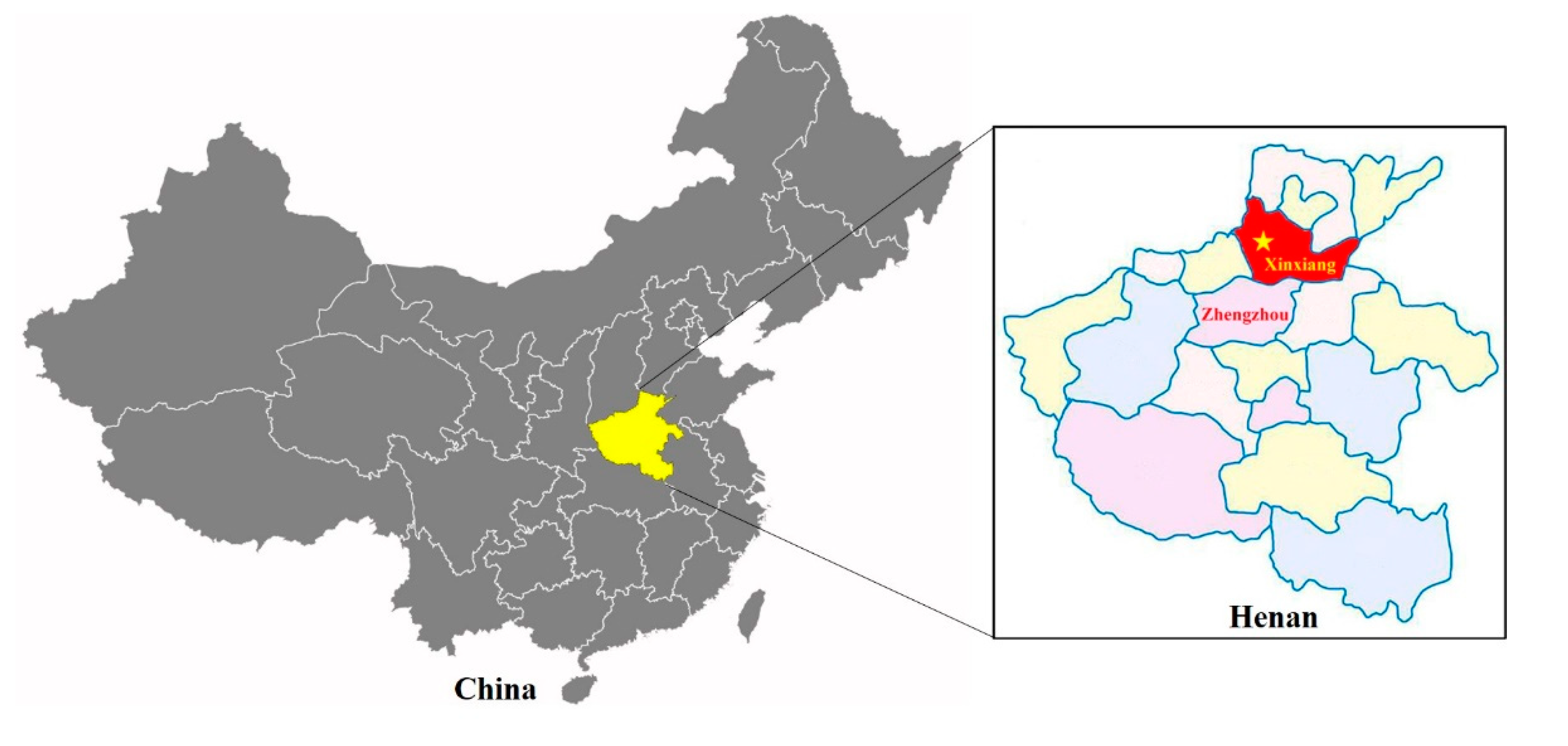
2.1. Engineering Geological Settings

Zhaogu No.1 coal mine is located in Xinxiang, Henan Province, China. The geographical location of the mine is shown in Figure 3. Its annual output is 4 Mt. The development of a single level (−525 m) with a vertical shaft is adopted. Inclined slice, fully mechanized longwall mining methods are used at 16011 mining panel, which advances along the strike. Naturally, the caving method is chosen to manage the roof behind the shields. At present, the coal seam being mined is a 2-1 coal seam, where the average thickness is 5.8 m and the average dip angle is 2.5°. The coal seam occurrence is stable and the geological structure is simple.
The coal-measure rock layers are mainly located in the lower Permian Shanxi Formation, and the average overburden depth of the coal seam is 560 m. The immediate roof of the coal seam is mainly composed of sandy mudstone with an average thickness of 6.3 m, and the overlying strata is a combination of interbedded sandy mudstone and medium-grained sandstone. The immediate floor of the coal seam is composed of sandy mudstone with an average thickness of 3.0 m.

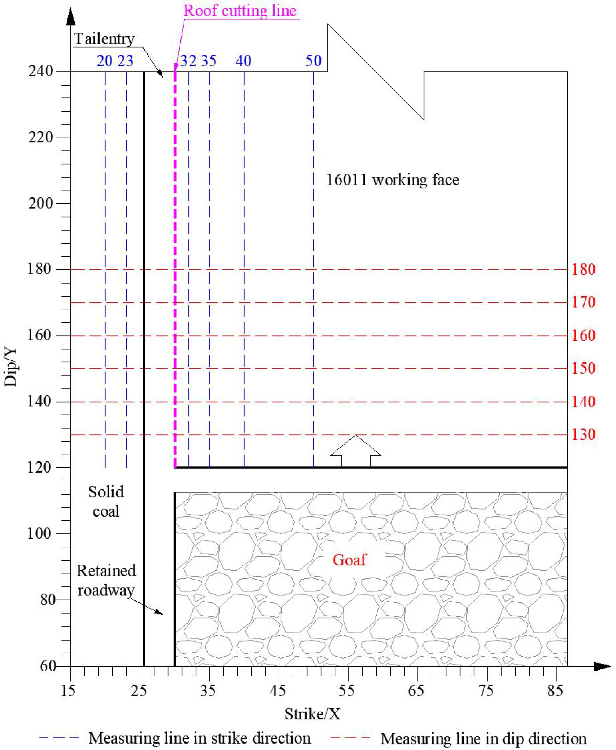
2.2. Working Face Overview

16011 panel is the first panel of the West 6 district in Zhaogu No.1 mine. The panel is 205 m wide along the dip and 650 m along the strike. RGERC was applied in the 16011 tail entry, which is located in the upper coal seam. The width and height of the roadway are 4500 mm and 3500 mm, respectively. The roadway roof support is mainly composed of the CRLDAC, anchor cables, and rebar bolts. The length of the CRLDAC is 11,300 mm, and the pattern is 1600 × 1600 mm². Directional pre-split blasting is adopted to accomplish the work of roof cutting. The designed roof cutting depth is 9000 mm, and the borehole slopes at an angle of 15° to the vertical. The detailed parameter of roadway support is shown in Figure 4.
The maximum allowable deformation of the CRLDAC is 350 mm, the constant resistance force is 30 ± 2 t, and the applied pretension should be no less than 28 t. The boreholes are arranged along the longitudinal direction of the roadway, the distance between the roadside coal wall and boreholes is 200 mm, and the distance between adjacent boreholes is 600 mm. After the roadway roof is reinforced with the CRLDAC, the ECT and explosive can be installed in the boreholes for directional pre-split blasting. The cracks generated by blasting penetrate the rock between the adjacent boreholes, thus forming a man-made fracture in the roof strata along the longitudinal direction of the roadway.

3. Stress Distribution and Transfer of Roadway Surrounding Rock in Front of the Working Face

If the roof strata of the coal seam before roof cutting can be regarded as a rectangular elastic thin plate fixed by a solid coal seam all around, then each rock layer becomes a stable transferring and bearing layer of the overburden. The internal stress distribution of the rock layer is uniform, and the pressure relief area is only formed within a certain range of the roadway surrounding rock after roadway excavation, and the roof structure does not change. However, after roof cutting, the roof structure is transformed into a composite structure composed of two parts (A and B), as shown in Figure 5. Part A is the roof of the roadway and the coal seam beside the roadway coal side, which can be regarded as the thin plate with three sides fixed and one side roller supported. Part B is the working face roof, which can be regarded as the thin plate with two sides fixed and two sides roller supported. Therefore, it can be inferred that roof cutting will significantly affect the structural continuity of the roadway roof strata, which will inevitably lead to the stress transfer and asymmetric distribution of surrounding rock stress.

3.1. The Stress Transfer of Roadway Surrounding Rock after Roof Cutting

FLAC3D simulation software was used to study the stress transfer of roadway surrounding rock caused by the change in roof structure. The length, width, and height of the established numerical model were 300 m, 300 m, and 80 m, respectively. In the model, the thickness of the strata above the coal seam was 64.2 m, and the thickness of the strata below the coal seam was 10 m. The mechanical parameters of the rock appearing in the model are shown in Table 1. Displacement boundaries were applied to the front, back, left, right, and bottom of the model. The upper surface of the model was a free surface applied stress boundary. A load (6.5 MPa) equal to the gravity of the overlying strata was applied on the upper surface of the model. The model calculation was based on the Mohr–Coulomb criterion.
After the roadway in the model is excavated, the surrounding rock forms a new stress equilibrium state. The stress distribution of the roadway surrounding rock is shown in Figure 6a. The shallow surrounding rock of the roadway is at a lower stress level due to the excavation induced unloading effect, and stress concentration is formed in the deep surrounding rock of the roadway. The maximum concentrated stress beside the roadway exceeds 11 MPa, and the stress concentration factor is greater than 1.6.
By comparing Figure 6b with Figure 6a, it is found that after roof cutting, the peak stress of the stress concentration area in the working face is reduced and the area is shifted to the deep and upper coal seam. At the same time, the stress concentration appears at the top of the blasting induced crack, and the maximum stress exceeds 11 MPa. However, in the coal seam beside the roadway mining side, the stress concentration area expands and shifts to the deep coal seam after roof cutting. The range of the pressure relief zone in the roadway roof is significantly increased, and the roadway roof stress within the height of roof cutting is generally below 3 MPa. In addition, the roadway floor strata is also relieved.
It is inferred that the existence of a pre-split blasting induced crack in the roadway roof significantly changes the stress distribution pattern of the roadway surrounding rock. During the downward transfer of the overburden load, stress is transferred to the deep coal seam away from the roadway and the blasting fracture, thus forming the asymmetry of the stress distribution on both sides of the roadway. The range of the stress-relief zone of the roadway surrounding rock is expanded, which is beneficial to the control of roadway surrounding rock, especially the roof. Therefore, the directional pre-split blasting of the roadway roof should be completed as soon as possible to reduce the roadway deformation before roadway development.

3.2. Distribution and Transfer of Front Abutment Pressure after Roof Cutting

At present, academia has reached a consensus that the overlying strata movement, such as roof collapse and strata deformation, caused by coal mining is the mechanical source of abutment pressure [27]. Combined with the theory of key strata, the abutment pressure is formed by the stress transfer from the overburden above the broken key strata to the coal-rock mass around the mining stope. It is obvious that the existence of a pre-split fracture changes the roof structure, which will inevitably affect the distribution of abutment pressure on the strike and dip.
In order to study the influence of roof cutting on the magnitude and distribution of front abutment pressure, several measuring lines were arranged in the coal seam on both sides of the roadway in front of the working face. The layout scheme of the measuring lines is shown in Figure 7. The distribution and variation of front abutment pressure on the strike and dip were monitored under the conditions of roof cutting and no roof cutting. A total of 6 measuring lines were arranged on the strike: 2 were located in the coal seam on the left side of the roadway, and the distance between the measuring lines and the roadway were 2.5 m and 5.5 m, respectively. The other 4 were located in the coal seam on the right side of the roadway, and the distance between the measuring lines and the roadway were 2 m, 5 m, 10 m, and 20 m, respectively. In addition, 6 measuring lines were also arranged along the inclined direction of the working face, and the distances between the measuring lines and the coal wall of the working face were 10 m, 20 m, 30 m, 40 m, 50 m, and 60 m, respectively.
The working face was mined in the model, and the variation of vertical stress on the measuring line in front of the working face was monitored and recorded. After the vertical stress caused by coal seam mining tended to be stable, the monitoring data was extracted, and the distribution of the front abutment pressure was analyzed. Figure 8a,b shows the distribution of front abutment pressure on the strike under the condition of no roof cutting and roof cutting, respectively. If the roadway roof was not split, the front abutment pressure on the left side of the roadway decreased with increased distance from the coal wall of the working face. The front abutment pressure on the other side increased rapidly in zone I and reached the peak value soon, then decreased gradually in zone II and tended to be stable in zone III. The length of zone I and II were 8 m and 42 m, respectively, and the sum (50 m) of their lengths was the length of zone influenced by front abutment pressure.
After roof cutting, the distribution of the front abutment pressure on the left side of the roadway had no change compared to that without roof cutting, but the value of the front abutment pressure decreased generally. At the same time, the front abutment pressure on the other side changed significantly. The length of zone I increased from 8 to 18 m, the length of zone II decreased from 42 to 37 m, and the length of zone influenced by the front abutment pressure increased to 55 m, which indicates that the peak front abutment pressure moves away from the coal wall of the working face. The magnitude of the abutment pressure on the measuring lines of X = 32 m, X = 35 m, and X = 40 m were obviously smaller than those without roof cutting, which indicates that roof cutting has an obvious pressure relief effect on the front abutment pressure. However, the range of pressure relief induced by roof cutting is not infinite, for the peak value of front abutment pressure on the monitoring line X = 50 m was greater than that without roof cutting. Therefore, the pressure relief range of roof cutting to the working face on the dip is no more than 20 m.
Figure 9a,b show the distribution of side abutment pressure at different positions in front of the working face under the conditions of no roof cutting and roof cutting, respectively. By comparing the two figures below, it was found that the side abutment pressure on both sides of the roadway showed the distribution characteristics of increasing rapidly at the beginning, then deceasing after reaching the peak value and reaching a stable state quickly with the increase in distance from the roadway. Roof cutting moved the peak of the side abutment pressure on both sides of roadway into the deeper part of the coal seam, but had little influence on the magnitude of the peak and stable value of the side abutment pressure. To sum up, roof cutting can promote the high side abutment pressure to transfer to the position away from the roadway and optimize the stress environment for roadway surrounding rock.
Figure 10 is the contour of vertical stress of the coal seam roof within 160 × 120 m² in front of the working face. It shows that the vertical stress contour on both sides of the roadway roof was transferred to the deeper part of the strata, and an obvious triangle pressure relief area was formed within 20 m in front of the working face end. The stress transfer and pressure-relief zone of the roof strata caused by roof cutting are of great significance for optimizing the stress environment of the roadway surrounding rock in the area affected by abutment pressure, and it is helpful to control the deformation of the roadway surrounding rock before entry development.

4. Stress Transfer of the Overlying Strata behind the Working Face

4.1. Stress Transfer between Overlying Strata

Stress change in roadway surrounding rock is attributed to mining-induced overlying strata movement, and the roadway roof is a load transfer structure of stress from the overlying strata to the roadway surrounding rock [28]. After the immediate roof behind the shields collapses, the caved rocks are loosely heaped up in the gob. As a result, the overlying rock strata loses effective support from the direction of the mined-out area, which inevitably causes asymmetric stress transfer when the overburden load is transferred downwards. There are two main paths of the stress transfer.
Path 1: the stress transfer of the overburden load to the roadway immediate roof and roadside coal seam. When the caved rocks are loose, its supporting capacity is small. Almost all the overburden load is transferred to the retained immediate roof through path 1 in Figure 11, thus forming a concentrated pressure in the roadway surrounding rock that is significantly higher than the original rock stress. This is the mechanical source of high concentrated stress and large deformations of roadway surrounding rock in the early stage of roadway retaining.
Path 2: the stress transfer from the overburden load to the caved rocks. At first, only a small part of the overburden load is transferred to the caved rocks through path 2 in Figure 11. However, with the subsiding of the overlying roof strata, the caved rocks are compacted, and its bearing capacity is gradually enhanced. The stress transferred from the overburden load to the caved rocks also gradually increases, and the internal stress of the caved rocks begins to recover. With the distance from the roadway increasing, the degree of stress recovery increases.
According to the above analysis, the stress transferred from the overlying rock strata to the roadway surrounding rock varies over time. With the continuous movement of the overlying rock strata, more and more overburden loads are transferred to the caved rocks and the stress concentration and large deformation of the roadway roof are gradually alleviated. When the caved rocks cannot be further compressed, the subsidence of the overlying rock strata tends to cease, and the internal stress distribution of the surrounding rock and the caved rocks becomes stable.
From the perspective of stress transfer, it was found that the recovery of the supporting capacity of the caved rocks makes a positive contribution to the stress transfer from the roadway roof to the gob, which plays an important role in alleviating the large deformation of the roadway surrounding rock and the asymmetric stress distribution of the mining stope. Therefore, through the directional pre-split blasting technology and reasonable design of roof cutting parameters, it is possible to actively control the collapse starting position, time, and the bulking factor of caved rocks. Therefore, it is also a success to bring the caved rocks into full use to control the stress transfer of the overburden load and optimize the stress environment of the roadway surrounding rock and the mining stope.
The height Hq of the roof cutting can be expressed as follows:
H q = H c Δ H 1 Δ H 2 K p 1
where Hc is the mining height of the working face, ΔH1 is the roof subsidence of the coal seam, and ΔH2 is the floor heave of the coal seam. Kp is the initial bulking factor of the caved rocks.
When the main roof strata break above the solid coal, articulated rock blocks A, B, and C are formed. At this time, rock block B rotates around the contact plane with block A. A lateral structural model of the roof strata during RGERC is shown in Figure 12.
According to the stress–strain relationship of caved rocks proposed by H. Yavuz (2004) [29], the internal stress σ of caved rocks can be expressed as follows:
σ = E 0 H i x ( K p 1 ) H q K p ( K p 1 ) H i x K p
where E0 is the initial elastic modulus of the caved rocks and can be obtained by Equation (3), and Hix is the subsidence of rock block B at a distance x from the roadway.
E 0 = 10.39 σ C 1.042 K p 7.7
where σC is the initial compressive strength of the caved rocks. Hix can be expressed as follows:
H i x = ( 1 + x L p + L e ) H i
where Le is the roadway width, Hi is the subsidence of rock block B at the roadway mining side, and Lp is the horizontal distance between the fracture line of the main roof and the roadway coal side and can be expressed as follows [30]:
L p = λ H c 2 tan φ 0 ln [ k γ H + c 0 tan φ 0 c 0 tan φ 0 + p x λ ]
where λ is the ratio of lateral to vertical stresses, φ0 is the internal friction angle of the coal-rock interface, c0 is the cohesion of the coal-rock interface, γ is the average unit weight of overburden rocks, H is the buried depth of the coal seam, and px is the support strength of the roadway coal side.
The subsidence Hi of rock block B at the roadway mining side can be obtained with respect to the bulking factor Ki as follows:
H i = ( K p K i ) H q
The variation of the bulking factor of the caved rocks at the roadway mining side with respect to the distance behind the working face was plotted as illustrated with scattered data in Figure 13. As a result of a 2D regression analysis, the best curve fit to the data obtained can be expressed with the following equation:
K i = 3.447 8.055 + L z 0.745 + 1.318
where Lz is the distance from the working face.
Neglecting the roof subsidence and floor heave in Equation (1), and by substitution of Equations (1), (3), (4), (6) and (7) into Equation (2) and taking Kp = 1.53, finally, the internal stress σ of the caved rocks can be expressed as follows:
σ = σ C 1.042 ( L z 0.745 8.233 8.055 + L z 0.745 ) ( x + L p + L e L p + L e ) [ 18.36 7.34 ( L z 0.745 8.233 8.055 + L z 0.745 ) ( x + L p + L e L p + L e ) ]
According to the analysis of Equation (8), the internal stress of the caved rocks gradually increases with the increase of the distance from the roadway and the working face. This means that with the subsidence of the main roof block and the movement of the overlying rock strata, the overburden load is gradually transferred to the caved rocks in the gob. The internal stress distribution of the caved rocks on the strike and dip is shown in Figure 14a,b. The development of the internal stress is more rapid if the distance from the working face increases on the strike. On the other hand, the pressure imposed on the main roof block is higher with the increase of the distance, which means that the restriction on the main roof block also increases. Finally, it can be inferred that with the movement of the overlying rock strata after mining, the stress transfer from the overburden load to the gob mainly develops towards the deeper part of the caved rocks on the strike and dip.
The internal stress distribution for the initial compressive strength from 20 to 35 MPa for a constant distance from the roadway mining side of 6 m was determined for the caved rocks by using Equation (8). As Figure 15a shows, with the increase of the initial compressive strength of the caved rocks, the internal stress of the caved rocks gradually increases. Considering that the initial compressive strength of the caved rocks is mainly determined by the lithology and bulking factor of the immediate roof strata, for a specific lithology, the technology of loose blasting can be adopted to reduce the fragmentation of the caved rocks so as to increase the initial compressive strength of the caved rocks. Figure 15b shows that the effective support of the roadway coal side can promote the transfer of the overburden load to the gob, and this promotion effect is constantly enhanced with the advancement of the working face. Therefore, the effective support of the roadway coal side is also indispensable.

4.2. Stress Transfer between Roadway Surrounding Rock and Support Structure

The mining induced overlying strata movement is the stress source of the roadway surrounding support structure [31]. The function of the supporting structure is to improve the integrity and strength of roadway surrounding rock through its own mechanical properties and the interaction with the surrounding rock so as to improve the local stress concentration and large deformation of roadway surrounding rock. Secondly, the roadway support structure transfers and absorbs the deformation energy of the surrounding rock through its own structural deformation, and establishes or strengthens the stress connection between the roof strata and between the roof and floor after roadway excavation [32].
The CRLDAC, with high pretension and constant resistance, is used to support the roadway roof together with the anchor bolts so that the shallow and deep rock strata of the roadway roof are anchored as a whole [33]. The roadway roof supported by the CRLDAC has the ability to transmit continuous stress in both the horizontal and vertical directions. On the other hand, a strong support structure such as the roadside hydraulic support is indispensable in the roadway behind the working face, because it has to resist large deformation of the roadway roof under the violent movement of the overlying rock strata. The existence of the support structure establishes the stress connection between the roadway surrounding rock and promotes the stress of the roadway surrounding rock to reach the equilibrium state.
In order to determine the reasonable strength of the temporary roadside support and its role in the stress transfer of the overburden load, let us assume that the immediate roof strata above the roadway becomes a whole block under the support of the CRLDAC. The immediate roof strata between the fracture line of the main roof and the roof cutting line are extracted for stress analysis, and the established mechanical model is shown in Figure 16. The lower edge of the model is subjected to the supporting stress σm of the solid coal seam and the supporting stress σe of the roadside support. The upper edge of the model is subjected to the force of the main roof block, which is simplified as a concentrated force Fr. The left edge of the model is a fixed boundary, which is subjected to bending moment Ma and shear force TA. Finally, the model is subjected to self-weight Fz. Note that the right edge of the model is simplified as a free boundary.
According to the elastoplastic theory, the supporting stress σm to the immediate roof by the solid coal seam can be expressed as follows [34]:
σ m = ( c 0 tan φ 0 + p x λ ) exp 2 tan φ 0 λ H c x c 0 tan φ 0
The self-weight Fz of the immediate roof can be expressed as follows:
F z = H r 2 ( L p + L e + H r tan α ) ( L p + L e ) γ
where Hr is the height of the immediate roof, α is the angle of the roof cutting line with respect to the vertical at the borehole, and γ′ is the average unit weight of the immediate roof.
To facilitate subsequent calculations, let Li = Lp + Le. Establishing a rectangular coordinate system as shown in Figure 16, the moments of the forces acting on the immediate roof to point O can be expressed as follows:
{ 0 L p [ ( c 0 tan φ 0 + p x λ ) exp 2 tan φ 0 λ H c x c 0 tan φ 0 ] x d x = M m σ e L s ( L i L s 2 ) = M e 1 6 σ tl H r 2 = M A 3 L i 3 H r + H r 2 tan α ( 6 L i 3 + 4 L i 2 H r + L i H r 2 tan 2 α ) γ 12 L i + 6 H r tan α = M z F r ( L i + H r tan α 2 ) = M r
where Mm, Me, Mz, and Mr are the moments of stresses σm, σe, Fz, and Fr to point O, respectively, Ls is the width of the roadside support, and σtl is the tensile strength of the immediate roof.
As ∑MO = 0, the concentrated force Fr can be expressed as follows:
F r = 2 ( M y + M e + M A M z ) L i + H r tan α
The mechanical analysis of key rock block B is carried out. Actually, the main roof strata break periodically in the form of “O-X” with the advance of the working face so that the main roof block above the roadway presents an arch-triangle block structure. The mechanical model of the arch-triangle block is shown in Figure 17. Key rock block B rotates around arbitrary line GH and subsides to the gob. The planes BCFE, ABED, and HGA’C’ are the contact planes between rock block B and adjacent rock blocks. Through the interaction between the rock blocks, rock block B is subjected to pressure TCB and TAB, and shear force FCB and FAB from blocks A and C, respectively.
A beam element with unit width perpendicular to rotation axis GH is extracted for force analysis. The lower edge of the unit rock beam is subjected to supporting stresses Fr and σm, respectively. At the same time, the unit rock beam is subjected to the resultant force Fj of its self-weight and the overburden load it controls. The left edge of the unit rock beam is subjected to horizontal pressure TAB and shear force FAB. The right edge of the unit rock beam is subjected to horizontal pressure T2 and shear force FCB, in which T1 is equal to TCBcosβ. β is the characteristic angle of rock block rupture, and can be determined as follows:
β = arctan ( 2 L L m )
where Lm is the periodic weighting interval of the main roof strata, and L is the length of the main roof block on the dip, and can be determined as follows:
L = L m ( L m H s 2 H m + 16 L m 2 4 H m 2 4 H m H s H s 2 s 2 + 3 2 )
where Hm is the height of the main roof, HS is the maximum subsidence of block B = Hq(KpKA), and Ka is the residual bulking factor of the caved rocks.
In the horizontal and vertical directions, the equilibrium equations of the pressure on the unit rock beam are established as follows:
{ T 1 = T C B cos β = T A B F r + 0 L cos θ 2 L i σ x d x + F C B F A B F j = 0
The moments of forces acting on the unit rock beam to the rotation axis GH can be expressed as follows:
{ F r ( L i + H r tan α 2 ) = M rGH 0 L cos θ 2 L i σ x ( x + L i ) d x = M x GH F C B ( L cos θ 2 + ( H m s ) sin θ ) = M CBGH T 1 ( ( 2 H m s ) cos θ ( L + s ) sin θ 2 ) = M 1 GH F j ( cos ( θ + δ ) 4 H m 2 + L 2 4 + ( H m s 2 ) sin θ ) = M jGH
where MrGH, MxGH, MCBGH, M1GH, and MjGH are the moments of stresses Fr, σx, FCB, T1, and Fj to rotation axis GH, respectively, and δ is the characteristic angle of the rock block rupture.
Moreover, the moments of forces acting on the unit rock beam to point O can be expressed as follows:
{ F r ( L cos θ 2 + ( H m s ) sin θ L i ) = M rO T A B ( ( H m s ) cos θ L sin θ 2 ) = M TABO F A B ( L cos θ 2 ( H m s ) sin θ ) = M FABO 0 L cos θ 2 L i σ m ( L cos θ 2 + ( H m s ) sin θ L i x ) d x = M mO F j ( cos ( δ θ ) 4 H m 2 + L 2 4 ) = M jO
where MrO, MTABO, MFABO, MmO, and MjO are the moments of stresses Fr, TAB, FAB, σm, and Fj to point O, respectively.
By substitution of Equations (12) and (13) into Equations (16) and (17), and then making ∑MGH = 0 and ∑Mo = 0, the forces acting on the unit rock beam from other rock blocks can be expressed as follows:
{ T A B = 2 ( M a M b ) s ( cos θ sin θ ) T C B = 2 ( M a M b ) s ( cos θ sin θ ) cos β F C B = 2 ( M a M b ) ( ( 2 H m s ) cos θ ( L + s ) sin θ ) 2 M b s ( sin θ cos θ ) s ( sin θ cos θ ) ( L cos θ + 2 ( H m s ) sin θ ) F A B = 2 ( M a M b ) ( 2 ( H m s ) cos θ L sin θ ) 2 M a s ( sin θ cos θ ) s ( sin θ cos θ ) ( L cos θ + 2 ( H m s ) sin θ )
For the convenience of calculation, the following substitutions are made in Equation (18):
{ M a = M jO M rO M mO M b = M rGH + M x GH M jGH
In order to ensure the stability of key rock block B in the subsiding process, it is necessary to prevent the relative dislocation between key rock blocks A and B. Therefore, rock block B must satisfy the following mechanical requirements:
F A B T A B tan ( φ β ) 1
where φ is the friction angle of the contact plane of key rock blocks A and B.
In order to obtain roadside support resistance Fe under the limit equilibrium state, it is necessary to let FAB = TABtan(φβ). Therefore, the final roadside support force is determined as follows:
F e = 2 M c s c ( cos θ sin θ ) 2 c ( M c M d ) ( a + b tan ( φ β ) ) s ( b 2 L i ) ( s sin θ s cos θ a b tan ( φ β ) ) ( L i + H r tan α ) ( a + b tan ( φ β ) ) + 2 ( M z M A M y ) 2 L i L s
For the convenience of calculation, the following substitutions are made in Equation (21):
{ M c = M jO M mO M d = M x GH M jGH a = 2 ( H m s ) cos θ L sin θ b = L cos θ + 2 ( H m s ) sin θ c = L i + H r tan α 2 L i L s

5. Field Monitoring

5.1. Stress Monitoring of Supporting Structures

After the roadway roof is supported by the CRLDAC, a pretension is applied to the anchor cable immediately. After that, under the influence of mining-induced pressure, the resistance of the anchor cable continues to increase until it reaches the constant resistance value. The unique mechanical characteristics of constant resistance and large deformation of the CRLDAC ensures that the supported roadway roof is always in a dynamic balance between high support strength and the roof subsidence so as to prevent possible roof failure due to stress accumulation. The in situ monitoring curve of the CRLDAC resistance is shown in Figure 18.
As shown in Figure 18, the installation position of the CRLDAC was 38 m in front of the working face, and a pretension of 282 kN was applied immediately after the installation. Then, due to the implementation of the advance directional pre-split blasting, the resistance force of the CRLDAC increased rapidly and then dropped. Therefore, the role of the CRLDAC in absorbing dynamic impact energy and ensuring the stability of support system was verified. As the working face continued to advance, the resistance force of the CRLDAC increased steadily and reached the peak value at 25 m behind the working face, which exceeded the design constant resistance of the CRLDAC by 350 kN. After that, the resistance force of the CRLDAC began to fluctuate around the constant resistance value, and at the same time, the CRLDAC deformed constantly to adapt to the roof subsidence and absorb the energy of the roof deformation
Under the pressure of the main roof blocks and overlying strata, the caved rocks in the gob may flow into the roadway if no restriction measures are taken. Therefore, considering the characteristics of large mining height in the 16011 working face, a retractable U-type steel structure was invented to constrain and shape the caved rocks beside the roadway so that the caved rocks in the gob formed a new roadway gangue side automatically. Although there is difficulty in directly monitoring the internal vertical stress of the caved rocks in the gob, we can monitor the lateral pressure between the caved rocks and the retractable U-type steel to study the evolution of the internal stress of caved rocks [35,36,37]. The layout and installation of the lateral pressure monitor are shown in Figure 19.
The monitoring curve of the lateral pressure on the gangue side of the 16011 tail entry is shown in Figure 20. When the distance behind the working face was 10–25 m, the lateral pressure of the caved rocks increased rapidly. When the distance behind the working face reached 25 m, the lateral pressure of the caved rocks reached 1.63 MPa, and then the lateral pressure plunged to about 1.35 MPa. With the advance of the working face, the lateral pressure of gangue began to increase continuously and slowly. It is speculated that the main roof strata or thick roof strata ruptured or collapsed at the position of 25 m behind the working face, and then the fluctuation of the lateral pressure was mainly caused by the change in the contact area between the caved rocks and the pressure monitor induced by the fragmentation change in the caved rocks. With the bulking factor of the caved rocks gradually stabilized, the fluctuation of the gangue lateral pressure also decreased significantly. When the distance behind the working face exceeded 200 m, the gangue lateral pressure reached 1.93 MPa and continued to increase slowly. According to the results of the above theoretical analysis, the vertical stress in the caved rocks 200 m behind the working face was 5.35 MPa, so the lateral pressure coefficient of the caved rocks here was 0.36.

5.2. Cooperative Deformation and Control of Roadway Surrounding Rock by Support Structure

The deformation curve of the surrounding rock of the 16011 tail entry obtained by monitoring is shown in Figure 21. When the distance behind the working face was 230 m, the roof and floor convergence of the retained roadway reached 1490 mm. Of this amount, the roof and floor convergence of the roadway in front of the working face was 180 mm, accounting for 87.9% of the total deformation. This shows that the severe surrounding rock deformation of RGERC is mainly caused by mining-induced overlying strata movement. In addition, the floor heave of the retained roadway was 1064 mm, and the roof subsidence was 426 mm, which shows that the roadway roof was effectively controlled under the pressure-relief effect of roof cutting and the combined support of the CRLDAC and roadside support. On the contrary, the roadway floor was not effectively supported, and the floor strata was composed of coal and sandy mudstone with low strength and belonged to expansive soft rock. In the process of stress transfer of the roadway surrounding rock, the stress on both sides of the roadway would be transferred downward to the floor strata and released through the roadway floor, resulting in severe roadway floor heave.
According to the relationship between surrounding rock deformations, the roof subsidence at a certain position is the sum of the separation of the roadway immediate roof and the rotation subsidence of the main roof. Then, as long as the subsidence and bed separation of the roadway roof are obtained, the rotation subsidence of the main roof block at this position can be obtained. According to the monitoring curve, when the distance behind the working face was 200 m, the roadway roof subsidence was 360 mm, and the immediate roof separation was 122 mm, then the rotation subsidence of the main roof block at this position was 238 mm. On the other hand, the rotation subsidence of the main roof block at a certain position should be the sum of the cutting height of the roadway roof and the mining height of the working face minus the current height of the caved rocks. The cutting height of the 16011 tail entry was 9000 mm, and the mining height of the 16011 working face was 3500 mm. When the distance behind the working face was 200 m, the bulking factor of the caved rocks beside the roadway was calculated as 1.36 according to Equation (7). Therefore, the rotation subsidence of the main roof block at the roadway gangue side was calculated to be 260 mm when the distance behind the working face is 200 m. Considering that the regression equation has some errors, it can be proved that the monitoring and regression analysis of the bulking factor of caved rocks is generally accurate, and it also indirectly verified the correctness of the stress transfer analysis between the roadway surrounding rock.
The structural deformation of the CRLDAC behind the working face was also recorded in Figure 21. The deformation of the CRLDAC mainly includes the structural deformation of the CRD itself and the tensile deformation of the steel strand. At the same time, the deformation of the CRLDAC is equal to the immediate roof separation. Therefore, when the structural deformation of the CRD 200 m behind the working face was 74 mm, according to the relationship between the CRLDAC deformation and the immediate roof separation, the elongation of the steel strand was calculated to be 48 mm. Assuming that the elongation of the steel strand is proportional to the tensile force, then the ultimate elongation of the steel strand with a diameter of 21.8 mm can be expressed as follows:
c y = ( L c L g L f ) η
where Lc is the length of the steel strand, Lg is the length of the CRLDAC anchoring section, Lf is the length of the exposed section of CRLDAC, and η is the elongation rate of the steel strand.
Letting Lc = 11,300 mm, Lg = 2000 mm, Lf = 300 mm, and η = 3%, and substituting these parameters into Equation (23), the ultimate elongation of the steel strand comes out to 270 mm. Since the allowable structural deformation of a CRD is 200 mm, it can be inferred that the CRD can still bear a deformation of 126 mm when the distance behind the working face exceeds 200 m. Moreover, when the structural deformation of the CRD exceeds its allowable deformation, the steel strand can still ensure the CRLDAC provides effective support for the roadway roof through its own tensile deformation, and the deformation allowance of the steel strand is 222 mm.
By analyzing the relationship between the surrounding rock deformation and CRLDAC in Figure 21, we found that the deformation of the CRLDAC was obviously smaller than the roadway roof subsidence, for the CRLDAC can only control the bed separation and expansion deformation of the roadway immediate roof. Therefore, in a roadway affected by mining pressure, a strong temporary support structure such as roadside hydraulic support is suggested to be adopted to control the rotation subsidence of the retained roadway roof so as to ensure the stability of the roof and floor strata during the process of the stress transfer of the roadway surrounding rock.

6. Conclusions

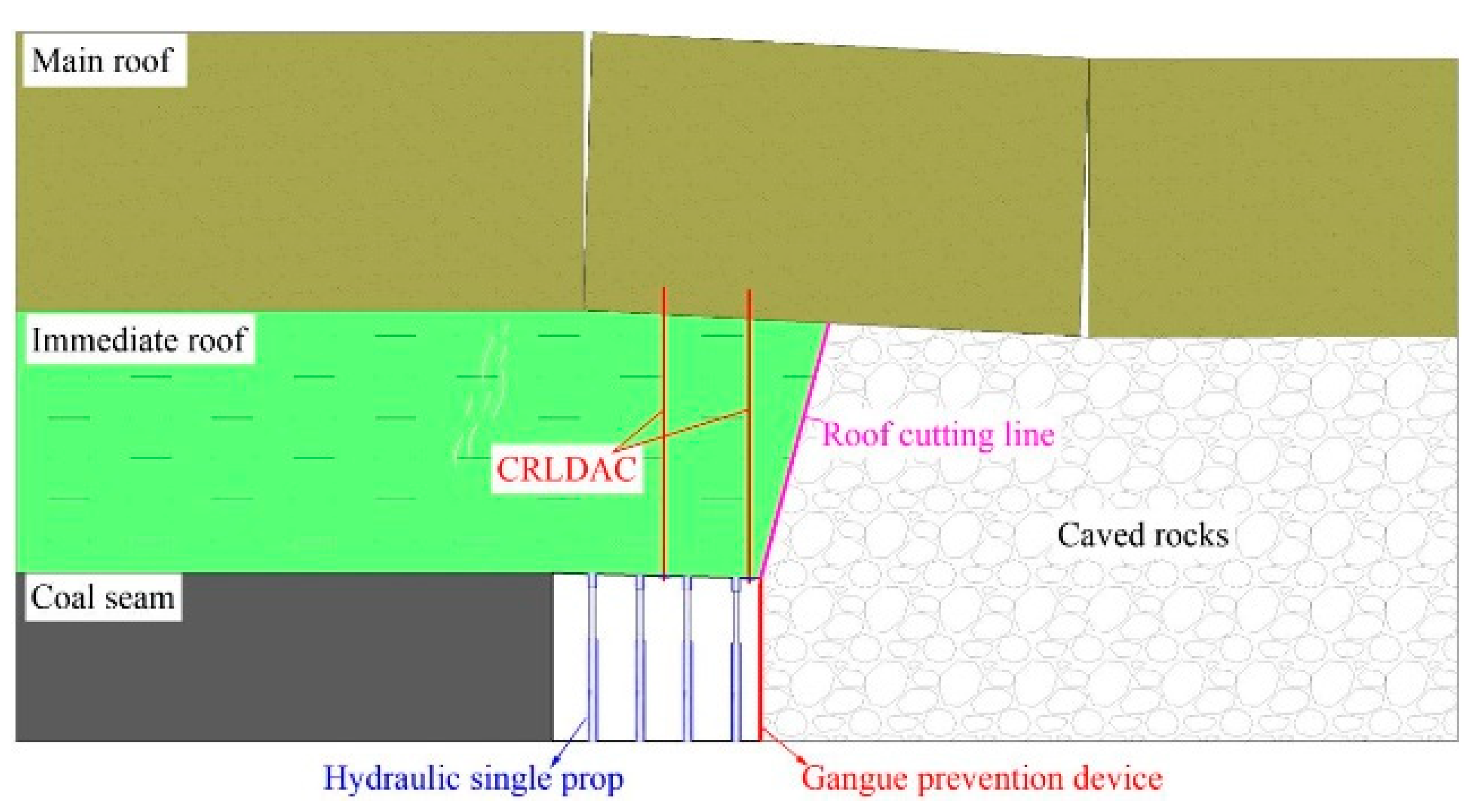
  • The key technology of RGERC is roof cutting. Roof cutting can actively change the structure and roadway roof conditions. Through numerical simulation, it was found that roof cutting makes the side abutment pressure transfer away from the blasting fracture and form an obvious triangle pressure-relief area in front of the working face. The stress environment of roadway surrounding rock is greatly improved.
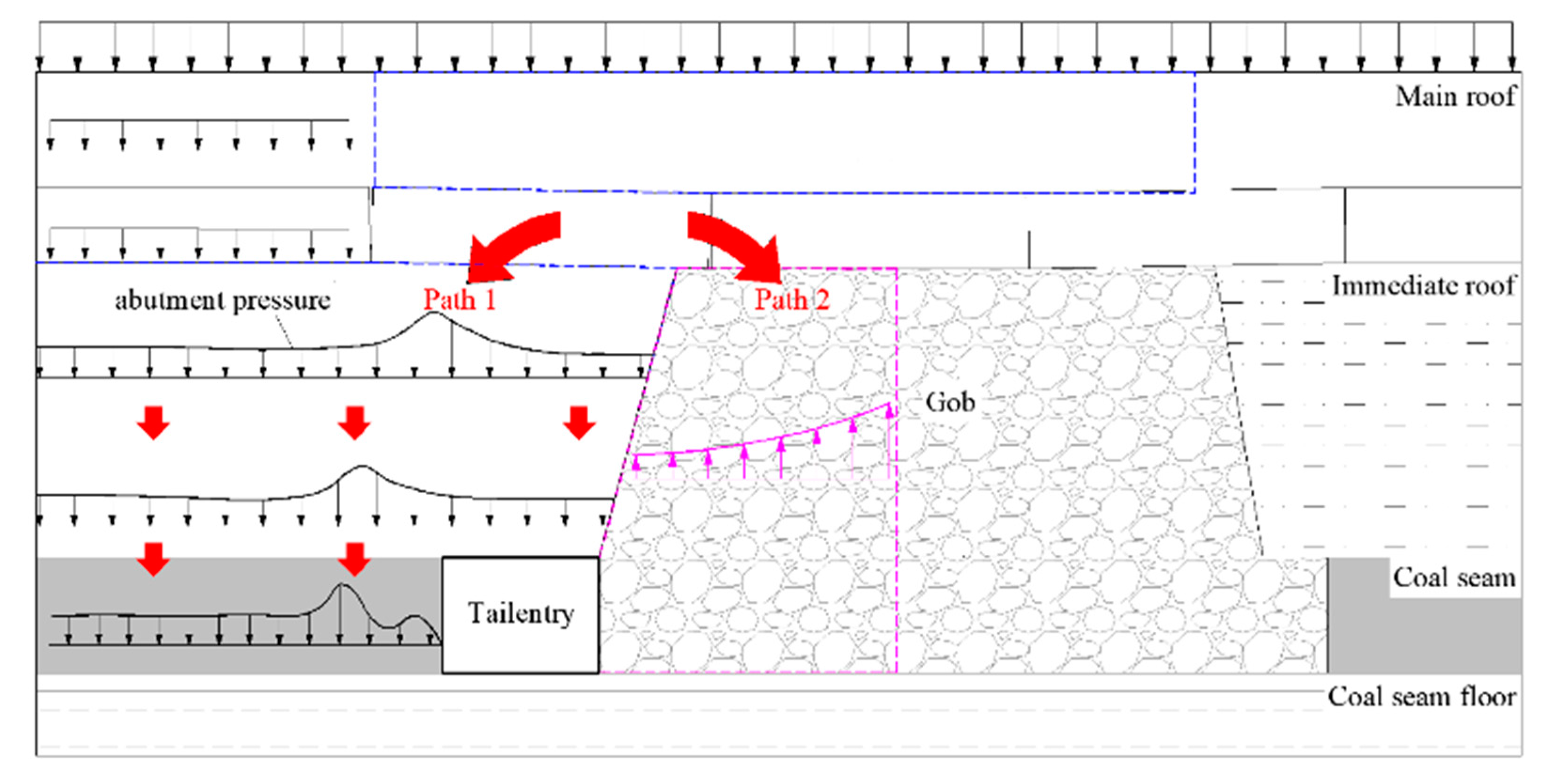
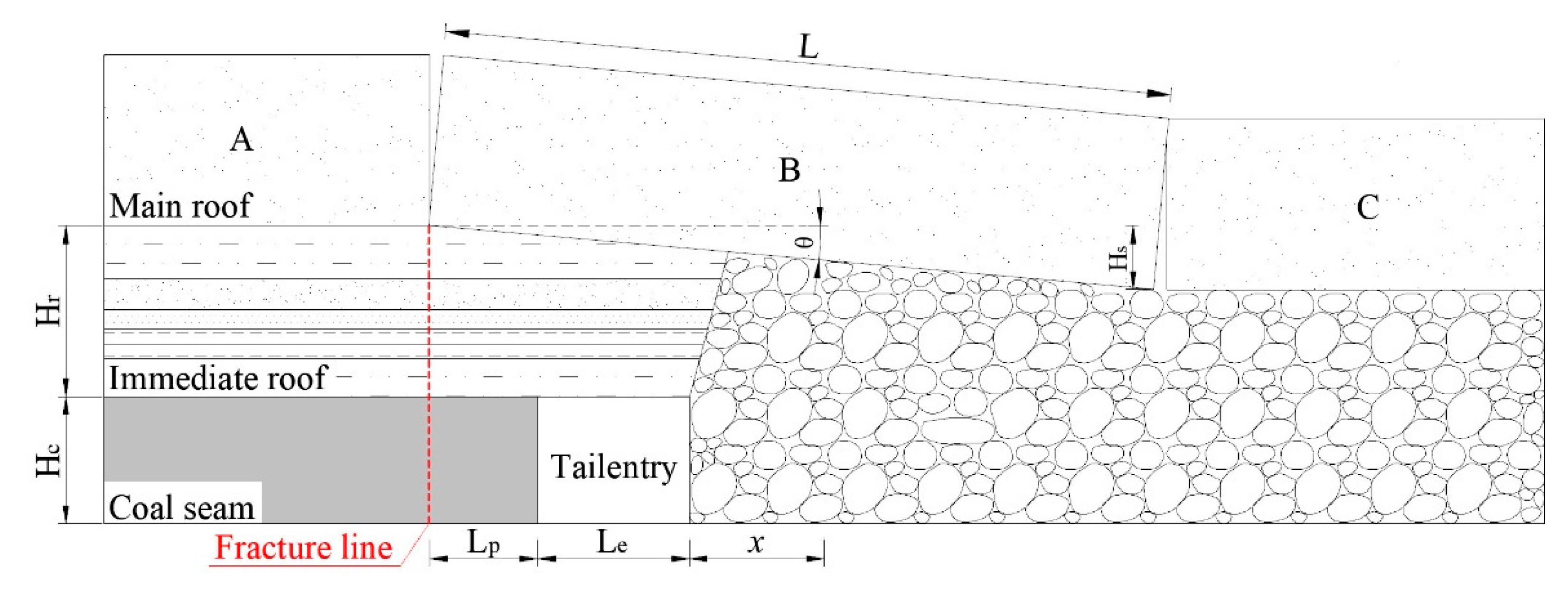
  • After the panel is mined, the structural asymmetry of the rock mass on both sides of the blasting fracture results in the asymmetrical distribution of the stress transferred from the overlying strata to the lower coal-rock mass, and the stress transfer changes with time. In the early stage of overburden movement, due to the small bearing capacity of caved rocks, the overburden load is mainly transferred to the roadway immediate roof, resulting in the stress concentration and severe deformation of the roadway surrounding rock. With additional movement of the overlying strata, the caved rocks are continuously compressed and its bearing capacity is restored. The stress transferred from the overburden load to the caved rocks also gradually increases. Based on the structural model of lateral roof strata, field monitoring and regression analysis of the bulking factor of caved rocks, the theoretical solution of the stress transferred to the gob was derived, and the distribution characteristics of the internal stress of caved rocks and its influencing factors were analyzed.
  • The shallow and deep strata of the roadway roof can be anchored into a whole by a CRLDAC so as to improve the overall strength of the roadway roof and the ability to transfer continuous stress. The temporary support in the retained roadway can control the rotation and subsidence of roadway roof with high support strength and establish the stress connection between the roadway surrounding rocks. The mechanical models of the immediate roof and the main roof were established, and then the critical roadside support force of RGERC was derived on the premise that the relative dislocation between key rock blocks A and B does not occur.
  • By monitoring the field stress and deformation of the surrounding rock of a retained roadway, it was concluded that the lateral pressure coefficient of the caved rocks at the roadway gangue side is 0.36. The stress transfer between the surrounding rocks and between the surrounding rock and the support structure were verified, as well as the relationship between the rotation subsidence of the main roof block and the variation of the bulking factor of caved rocks. It was also inferred that the deformation of the surrounding rock, especially the roof and floor, is mainly controlled by the temporary support in the retained roadway during the dynamic pressure influence period, and the CRLDAC can meet the roof support requirements in service life due to its enough deformation allowance.

Author Contributions

All the authors contributed to this paper. Z.G. conceived and designed the research. H.W. and Z.M. performed the theoretical analysis and field tests. X.K. and X.Z. assisted in the field monitoring process. P.W. performed the English editing and review. All authors have read and agreed to the published version of the manuscript.

Funding

This work is supported by the National Natural Science Foundation of China (No. 51674265, 51804209) and the State Key Research Development Program of China (No. 2016YFC0600900), which are gratefully acknowledged.

Data Availability Statement

The data is available from the authors upon request.

Conflicts of Interest

The authors declare no conflict of interest.

References

  1. Zhang, Z.; Bai, J.; Chen, Y.; Yan, S. An innovative approach for gob-side entry retaining in highly gassy fully-mechanized longwall top-coal caving. Int. J. Rock Mech. Min. Sci. 2015, 80, 1–11. [Google Scholar] [CrossRef]
  2. Han, C.L.; Zhang, N.; Li, B.Y.; Si, G.Y.; Zheng, X.G. Pressure relief and structure stability mechanism of hard roof for gob-side entry retaining. J. Cent. South Univ. 2015, 22, 4445–4455. [Google Scholar] [CrossRef]
  3. Gong, P.; Ma, Z.; Ni, X.; Zhang, R.R. Floor Heave Mechanism of Gob-Side Entry Retaining with Fully-Mechanized Backfilling Mining. Energies 2017, 10, 2085. [Google Scholar] [CrossRef] [Green Version]
  4. Wang, Q.; He, M.; Yang, J.; Gao, H.; Jiang, B.; Yu, H. Study of a no-pillar mining technique with automatically formed gob-side entry retaining for longwall mining in coal mines. Int. J. Rock Mech. Min. Sci. 2018, 110, 1–8. [Google Scholar] [CrossRef]
  5. He, M.; Gong, W.; Wang, J.; Qi, P.; Tao, Z.; Du, S.; Peng, Y. Development of a novel energy-absorbing bolt with extraordinarily large elongation and constant resistance. Int. J. Rock Mech. Min. Sci. 2014, 67, 29–42. [Google Scholar] [CrossRef]
  6. Zhang, G.F.; Wang, E.Y.; Xu, L.Y. Mechanical characteristics of high constant resistance and large deformation anchor rope in coal mines. Chin. J. Rock Mech. Eng. 2016, 35, 2033–2043. [Google Scholar]
  7. Zhang, X.Y.; Ronald, Y.S.; Gao, Y.B.; Liu, C.K.; Zhang, C.; Yang, J.; He, M.C. Field experiment on directional roof presplitting for pressure relief of retained roadways. Int. J. Rock Mech. Min. Sci. 2020, 134, 104436–104448. [Google Scholar] [CrossRef]
  8. Hu, J.; He, M.; Wang, J.; Ma, Z.; Wang, Y.; Zhang, X. Key Parameters of Roof Cutting of Gob-Side Entry Retaining in a Deep Inclined Thick Coal Seam with Hard Roof. Energies 2019, 12, 934. [Google Scholar] [CrossRef] [Green Version]
  9. Yang, X.; Liu, C.; Sun, H.; Yue, S.; Ji, Y.; Zhang, X.; Hou, L. Research on the Deformation Mechanism and Directional Blasting Roof Cutting Control Measures of a Deep Buried High-Stress Roadway. Shock. Vib. 2020, 2020, 6742504. [Google Scholar] [CrossRef]
  10. Gao, Y.B.; Yang, J.; He, M.C.; Wang, Y.J.; Gao, Q. Mechanism and control techniques for gangue rib deformations in gob-side entry retaining formed by roof fracturing in thick coal seams. Chin. J. Rock Mech. Eng. 2017, 36, 2492–2502. [Google Scholar]
  11. Ma, Z.; Wang, J.; He, M.; Gao, Y.; Hu, J.; Wang, Q. Key Technologies and Application Test of an Innovative Noncoal Pillar Mining Approach: A Case Study. Energies 2018, 11, 2853. [Google Scholar] [CrossRef] [Green Version]
  12. Ma, X.G.; He, M.C.; Li, Z.; Liu, Y.X.; Yu, G.Y.; Du, H.R. Key parameters of gob-side entry retaining automatically formed by roof cutting and blasting in compound roof condition. J. China Univ. Min. Technol. 2019, 48, 236–246. [Google Scholar]
  13. Chen, S.Y.; Zhao, F.; Wang, H.J.; Yuan, G.X.; Guo, Z.B.; Yang, J. Determination of key parameters of gob-side entry retaining by cutting roof and its application to a deep mine. Rock Soil Mech. 2019, 40, 332–342. [Google Scholar]
  14. Hu, C.W.; Wang, J.H.; He, M.C.; Wang, X.L.; Wang, J.Z.; Zhang, Z. Key parameters of Gob-side Entry Retaining by Roof Cutting in Medium-thick Coal Seam. Coal Sci. Tech. 2020. [Google Scholar]
  15. Zhang, G.F.; He, M.C.; Yu, X.P.; Huang, Z.G. Research on the Technique of No-Pillar Mining with Gob-Side Entry Formed by Advanced Roof Caving in the Protective Seam in Baijiao Coal Mine. J. Min. Saf. Eng. 2011, 28, 511–516. [Google Scholar]
  16. Zhen, E.; Gao, Y.; Wang, Y.; Wang, S. Comparative Study on Two Types of Nonpillar Mining Techniques by Roof Cutting and by Filling Artificial Materials. Adv. Civ. Eng. 2019, 2019, 5267240. [Google Scholar] [CrossRef] [Green Version]
  17. Wang, Y.; Gao, Y.; Wang, E.; He, M.; Yang, J. Roof Deformation Characteristics and Preventive Techniques Using a Novel Non-Pillar Mining Method of Gob-Side Entry Retaining by Roof Cutting. Energies 2018, 11, 627. [Google Scholar] [CrossRef]
  18. Li, L.F.; Li, G.; Gong, W.L.; Wang, J.; Deng, H.L. Energy evolution pattern and roof control strategy in non-pillar mining method of gob-side entry retaining by roof cutting—A case study. Sustainability 2019, 11, 7029. [Google Scholar] [CrossRef] [Green Version]
  19. Liu, J.; He, M.; Wang, Y.; Huang, R.; Yang, J.; Tian, X.; Ming, C.; Guo, S. Stability Analysis and Monitoring Method for the Key Block Structure of the Basic Roof of Noncoal Pillar Mining with Automatically Formed Gob-Side Entry. Adv. Civ. Eng. 2019, 2019, 5347683. [Google Scholar] [CrossRef]
  20. Gao, Y.B.; Guo, Z.B.; Yang, J.; Wang, J.; Wang, Y.J. Steady analysis of gob-side entry retaining formed by roof fracturing and control techniques by optimizing mine pressure. J. China Coal Soc. 2017, 42, 1672–1681. [Google Scholar]
  21. Liu, H.; Dai, J.; Jiang, J.; Wang, P.; Yang, J. Analysis of Overburden Structure and Pressure-Relief Effect of Hard Roof Blasting and Cutting. Adv. Civ. Eng. 2019, 2019, 1354652. [Google Scholar] [CrossRef] [Green Version]
  22. He, M.C.; Gao, Y.B.; Yang, J.; Guo, Z.B.; Wang, E.Y.; Wang, Y.J. An energy-gathered roof cutting technique in no-pillar mining and its impact on stress variation in surrounding rocks. Chin. J. Rock Mech. Eng. 2017, 36, 1314–1325. [Google Scholar]
  23. He, M.C.; Chen, S.Y.; Guo, Z.B.; Yang, J.; Gao, Y.B. Control of surrounding rock structure for gob-side entry retaining by cutting roof to release pressure and its application. J. China Univ. Min. Technol. 2017, 46, 959–969. [Google Scholar]
  24. Li, P.; Lai, X.P.; Gong, P.L.; Su, C.; Suo, Y.L. Mechanisms and applications of pressure relief by roof cutting of a deep-buried roadway near gobs. Energies 2020, 13, 5732. [Google Scholar] [CrossRef]
  25. Wang, Y.J.; He, M.C.; Zhang, K.X.; Yang, J.; Zhen, E.Z.; Zhu, Z.; Gao, Y.B.; Ma, Z.M. Strata behavior characteristics and control countermeasures for the gateroad surroundings in innovative non-pillar mining method with gateroad formed automatically. J. Min. Saf. Eng. 2018, 35, 677–685. [Google Scholar]
  26. Zhang, Y.; Xu, H.; Song, P.; Sun, X.; He, M.; Guo, Z. Stress Evolution Law of Surrounding Rock with Gob-Side Entry Retaining by Roof Cutting and Pressure Release in Composite Roof. Adv. Mater. Sci. Eng. 2020, 2020, 1961680. [Google Scholar] [CrossRef]
  27. Qian, M.G.; Shi, P.W.; Xu, J.L. Mining Pressure and Strata Control; China University of Mining and Technology Press: Xuzhou, China, 2010; pp. 137–145. [Google Scholar]
  28. Zhang, N.; Han, C.L.; Kan, J.G.; Zheng, X.G. Theory and practice of surrounding rock control for pillarless gob-side entry retaining. J. China Coal Soc. 2014, 39, 1635–1641. [Google Scholar]
  29. Yavuz, H. An estimation method for cover pressure re-establishment distance and pressure distribution in the gob of longwall coal mines. Int. J. Rock. Mech. Min. Sci. 2004, 41, 193–205. [Google Scholar] [CrossRef]
  30. Li, Y.F.; Hua, X.Z.; Cai, R.C. Mechanics analysis on the stability of key block in the gob-side entry retaining and engineering application. J. Min. Saf. Eng. 2012, 29, 357–364. [Google Scholar]
  31. Han, C.L.; Zhang, N.; Qian, D.Y.; Xue, B. Optimization analysis of span-depth ratio for roof safety control in gob-side entry retaining under large mining height. J. Min. Saf. Eng. 2013, 30, 348–354. [Google Scholar]
  32. Han, C.L.; Zhang, N.; Li, G.C.; Li, B.Y.; Wu, H. Stability analysis of compound bearing structure of gob-side entry retaining with large mining height. Chin. J. Geotech. Eng. 2014, 36, 969–976. [Google Scholar]
  33. Fu, Y.K.; Ju, W.J.; Wu, Y.Z.; Chen, J.Q.; Jiao, J.K.; Liu, K.L. Mechanism and practice of energy absorption and anti-scour of bolt (cable) in deep mining roadway. J. China Coal Soc. 2020. [Google Scholar] [CrossRef]
  34. Hou, C.J.; Ma, N.J. Stress in in-seam roadway sides and limit equilibrium zone. J. China Coal Soc. 1989, 14, 21–29. [Google Scholar]
  35. Feng, G.; Wang, P.; Chugh, Y.P. Stability of Gate Roads Next to an Irregular Yield Pillar: A Case Study. Rock Mech. Eng. 2018, 52, 2741–2760. [Google Scholar] [CrossRef]
  36. Feng, G.; Wang, P. Stress environment of entry driven along gob-side through numerical simulation incorporating the angle of break. Int. J. Min. Sci. Technol. 2020, 30, 189–196. [Google Scholar] [CrossRef]
  37. Feng, G.; Wang, P. Simulation of recovery of upper remnant coal pillar while mining the ultra-close lower panel using longwall top coal caving. Int. J. Min. Sci. Technol. 2020, 30, 55–61. [Google Scholar] [CrossRef]
Figure 1. Schematic diagram of RGERC.
Energies 14 01237 g001
Figure 2. Mechanical schematic of CRLDAC and roof pre-split blasting: (a) mechanical properties and supporting principle of CRLDAC and (b) 3D profile of roof cutting in RGERC.
Energies 14 01237 g002
Figure 3. Location of Zhaogu No.1 coal mine.
Energies 14 01237 g003
Figure 4. Roadway support and roof cutting scheme of the 16011 tail entry: (a) roadway support scheme of the roadway cross section and (b) roof support and cutting scheme.
Energies 14 01237 g004
Figure 5. Influence of roof cutting on the roadway roof structure.
Energies 14 01237 g005
Figure 6. Influence of roof cutting on the stress transfer of roadway surrounding rock: (a) no roof cutting and (b) roof cutting.
Energies 14 01237 g006
Figure 7. Layout of the abutment pressure monitoring line.
Energies 14 01237 g007
Figure 8. Distribution of front abutment pressure on the strike: (a) no roof cutting and (b) roof cutting.
Energies 14 01237 g008
Figure 9. Distribution of side abutment pressure in front of the working face: (a) no roof cutting and (b) roof cutting.
Energies 14 01237 g009
Figure 10. Abutment pressure distribution of roof strata in front of the working face: (a) no roof cutting and (b) roof cutting.
Energies 14 01237 g010
Figure 11. Mechanism of stress transfer between roadway surrounding rock after mining.
Energies 14 01237 g011
Figure 12. Lateral structure model of roof strata during RGERC.
Energies 14 01237 g012
Figure 13. Field observation and regression analysis on the bulking factor of the caved rocks at the roadway mining side.
Energies 14 01237 g013
Figure 14. Internal stress distribution of the caved rocks on the strike and dip: (a) on the strike and (b) on the dip.
Energies 14 01237 g014
Figure 15. Internal stress distribution of the caved rocks influenced by the parameters of the initial compressive strength and the support strength of the roadway coal side: (a) initial compressive strength and (b) support strength of the roadway coal side.
Energies 14 01237 g015
Figure 16. Mechanical model of the roadway immediate roof.
Energies 14 01237 g016
Figure 17. Mechanical model of key rock block B of the main roof.
Energies 14 01237 g017
Figure 18. Force monitoring curve of the CRLDAC.
Energies 14 01237 g018
Figure 19. Lateral pressure monitoring of roadway gangue side: (a) the layout of the monitor and (b) the installation of the monitor.
Energies 14 01237 g019
Figure 20. Monitoring curve of the lateral gangue pressure.
Energies 14 01237 g020
Figure 21. Deformation of the roadway surrounding rock and the supporting structure: (a) deformation of the roadway roof and floor and (b) deformation of the roof strata and CRLDAC.
Energies 14 01237 g021
Table 1. Lithology and rock mechanical parameters.
LithologyDensity
(kg/m3)
Bulk Modulus
(103 MPa)
Shear Modulus
(103 MPa)
Friction Angle (°)Cohesion
(MPa)
Tensile Strength (MPa)
Overlying strata23003.21.6331.60.7
Sandy mudstone25503.71.8322.21.2
Fine sandstone24302.51.7302.41.4
Medium sandstone26803.91.9382.21.6
Coal seam 2-113301.90.6240.80.5
Publisher’s Note: MDPI stays neutral with regard to jurisdictional claims in published maps and institutional affiliations.

