Article

Hybrid Output Voltage Modulation (PWM-FSHE) for a Modular Battery System Based on a Cascaded H-Bridge Inverter for Electric Vehicles Reducing Drivetrain Losses and Current Ripple †

1
Department of Electrical Engineering, Chalmers University of Technology, Hörsalsvägen 11, 41258 Gothenburg, Sweden
2
Department of Electrical Engineering, Bundeswehr University Munich, Werner-Heisenberg-Weg 39, 85579 Neubiberg, Germany
*
Author to whom correspondence should be addressed.
This article is a post conference article of the paper (Output Voltage Synthesis of a Modular Battery System based on a Cascaded H-Bridge Multilevel Inverter Topology for Vehicle Propulsion: Multilevel Pulse Width Modulation vs. Fundamental Selective Harmonic Elimination. In Proceedings of the 2020 IEEE Transportation Electrification Conference Expo (ITEC), Chicago, IL, USA, 23–26 June 2020), published at the IEEE ITEC 2020, Chicago, USA.
Energies 2021, 14(5), 1424; https://doi.org/10.3390/en14051424
Submission received: 25 January 2021 / Revised: 13 February 2021 / Accepted: 22 February 2021 / Published: 5 March 2021
(This article belongs to the Special Issue Building Automation and Special Electrical Systems)

Abstract

:
This paper shows a preliminary study about the output voltage modulation of a modular battery system based on a seven-level cascaded H-bridge inverter used for vehicle propulsion. Two generally known modulation techniques, pulse width modulation (PWM) and fundamental selective harmonic elimination (FSHE), are extensively compared for such an innovative modular battery system inverter considering EVs’ broad torque-speed range. The inverter and the battery losses, as well as the inverter-induced current THD, are modeled and quantified using simulations. At low speeds, if the modulation index M is below 0.3, FSHE induces a high current THD (>>5%) and, thus, cannot be used. At medium speeds, FSHE reduces the drivetrain losses (including the battery losses), while operating at higher speeds, it even reduces the current THD. Thus, an individual boundary between multilevel PWM and FSHE can be determined using weightings for efficiency and current quality. Based on this, a simple hybrid modulation technique is suggested for modular battery system inverters, improving the simulated drive cycle efficiency by a maximum of 0.29% to 0.42% for a modeled small passenger vehicle. Furthermore, FSHE’s high speed dominance is demonstrated using a simple experimental setup with an inductive load.

1. Introduction

The two-level inverter topology is predominantly used in today’s electric vehicles (EVs) [1,2]. A classical traction battery pack, as schematically depicted in Figure 1a, consists of a large number of series and parallel connected battery cells in order to meet the vehicle’s energy and power requirements [3,4,5,6]. To operate each cell within its safe operating boundaries, passive balancing is most commonly used [7,8], dissipating excessive charge using bleeding resistors when charging. Since no charge exchange is taking place between series cell strings during discharging, the usable capacity of the battery pack is constrained by the parallel cell strand with the lowest capacity (bottle neck). On the one hand, active balancing [9] or dynamic reconfiguration topologies [10] could increase the energy utilization and the battery lifetime, whereas the system costs would be significantly increased as well. On the other hand, a modular battery system, as depicted in Figure 1b, in combination with a multilevel inverter (MLI) topology can cost-effectively combine traction inverter and battery management functionality [11] without individual cells acting as bottle necks.
Employing a cascaded H-bridge converter topology, the battery packs in each phase can be drained by their individual capacity [12,13], sometimes referred to as proactive balancing, and zero sequence currents can be used at standstill to effectively transfer charges between modules of different phases, similar as described in [14]. For each small battery pack, passive balancing should be applied. Additionally, using a multilevel converter topology reduces the conducted emissions [13,15] and allows for a limp home mode [16,17]. A major drawback of MLI topologies is that these increase the ohmic battery losses, since the battery packs are stressed with strong current pulses ranging from DC up to a couple of k Hz . It has been controversially discussed whether these current pulses cause an additional rapid aging of the battery cells, but this controversy has been proven wrong, except for the increased rms current [18,19,20].
As described in [21], there are multiple techniques to modulate the output voltage of an MLI. Thus, the question arises, which method is the best when operating a modular battery inverter system? In [11,22,23,24] the authors have investigated the energy efficiency of multilevel propulsion inverters using only multilevel PWM for the entire operating range of a vehicle (considering variable output frequency and also low modulation indices). Besides multilevel PWM or space vector modulation (SVM) [21], fundamental frequency switching techniques as nearest-level control [25] or selective harmonic elimination (SHE) [26] are used to synthesize MLIs’ desired output voltage. These reduce the switching losses, but induce low-order voltage harmonics. Thus, fundamental switching techniques do not seem suitable for low modulation indices. Consequently, it might be beneficial to combine both SHE and PWM for EV’s broad torque-speed range. For example, selective harmonic elimination PWM (SHE-PWM) is such a combined approach. A predefined number of pulse transition angles is used to mitigate a selection of low order harmonics [27]. Nonetheless, due to the increased number of switching angles, the SHE-PWM optimization problem is more intricate, often resulting in discontinuities of the switching angles relative to the modulation index [27,28]. Hence, the available literature [21,25,26,27,28,29,30,31,32,33] is only covering grid-tied converter applications, operating with constant output frequency and modulation indices M higher than 0.65. Since standard PWM typically shows a better dynamic performance over a broad modulation index range than FSHE or SHE-PWM, the authors of [34] were the first to suggest to use FSHE at higher speeds ( M 0.5 ) and PWM at lower speeds ( M < 0.5 ) for a seven-level inverter to achieve an improved output current quality with reduced switching losses in comparison to using only PWM. Since the method in [34] describes how to balance the charges of the individual DC sources and the FSHE optimization problem can be easily solved, it seems very suitable for a CHB drivetrain with individual battery packs. However, no quantification/analysis of the reduced energy losses or the improved current THD in comparison when using only PWM for the broad torque-speed range of a vehicle has been provided in [34] and, further, the optimal boundary (M ≈ 0.5) between PWM and FSHE was not verified.

Research Objective

The objective of this paper’s preliminary study is to show if the energy efficiency and the current quality of an EV with a modular battery system inverter can be actually enhanced when using PWM at lower speeds and FSHE at higher speeds. Furthermore, the possible enhancement should be quantified for a small passenger vehicle.
In extension to [1], the analysis of this paper considers the ohmic battery losses, the drive cycle losses are quantified and FSHE’s high speed dominance is demonstrated using a simple experimental setup with an inductive load.

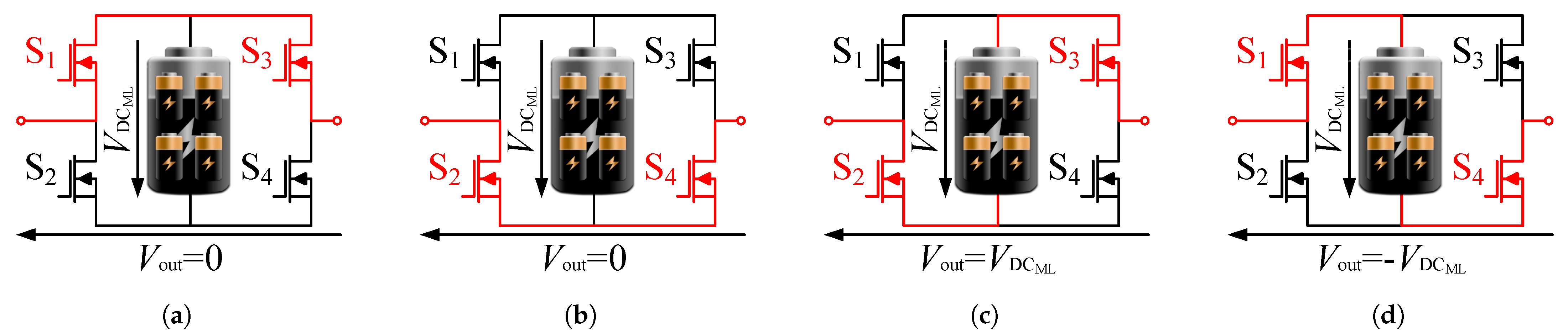
2. Cascaded H-Bridge Inverter Topology and Its Output Voltage Modulation

The cascaded H-bridge inverter topology can be used to realize a modular battery system. Each of the modularized battery packs is equipped with an individual H-bridge converter. As shown in Figure 2, the four switches of an H-bridge are operated in pairs, resulting in four valid switching combinations.
Consequently, each H-bridge can generate three valid output voltage levels according to
V out = { + V DC ML , V DC ML , 0 } .
Connecting a number of n H-bridges per phase in series, a cascaded H-bridge converter topology can be formed. As can be seen from the analyses presented in [11,23,35,36], a number of three submodules per phase is often selected for vehicles’ drivetrain, achieving a seven-level inverter, as depicted in Figure 3.
The instantaneous phase voltage can be calculated by the superposition of the output voltages of the individual H-bridge modules according to
v ph = v az = j = 1 n V out , j .
For the time duration of one electrical period, the individual battery packs are unevenly drained/charged. Thus, to keep the battery packs balanced during motor operation, the controller makes sure to use the battery pack with the highest and lowest voltage to the largest and smallest extent, respectively. This simple approach is independent of the modulation technique and it can be applied vice versa during generator mode. A more advanced approach should be used when balancing also the battery temperatures [37].

2.1. Multilevel Pulse Width Modulation

Different variants of PWM methods are used to modulate the desired three-phase output voltages [21,25]. Using a multilevel PWM technique, the desired three-phase reference voltages are compared with several high frequency triangular carriers, yielding the switching pattern for the inverter’s semiconductor switches. The number of triangular carriers usually corresponds to the number of output voltage levels L minus one. Within the scope of this paper, phase-disposition PWM (PD-PWM) is considered. This means, that the individual carrier waves of all half-bridges are just level-shifted, but their phase angles are constant. In comparison to other PWM methods (phase opposition disposition (POD) or alternative phase opposition disposition (APOD)), PD-PWM introduces the lowest current harmonic distortion by shifting a large portion of the harmonic energy content into the common mode carrier harmonics [21]. Figure 4 shows the output voltage modulation for a seven-level converter using PD-PWM for a modulation index M = 0.9 and a relative fundamental frequency of f 1 / f sw = 0.04 .

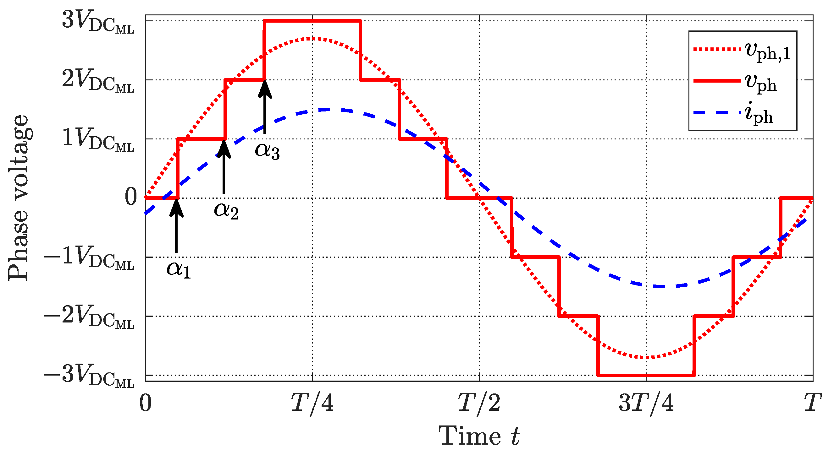
2.2. Fundamental Selective Harmonic Elimination

Another category of techniques to synthesize the desired three-phase output voltages is fundamental frequency switching [21,25,26]. Each battery module is activated in forward and reverse direction at most once per fundamental period. With the help of the insertion angles or pulse transition angles
α = α 1 α 2 α n T
the output voltages of the individual H-bridges can be described as
V out , j ( α j ) = + V DC ML ; if α j ω t π α j V DC ML ; if π + α j ω t 2 π α j 0 ; else
with j = 1 , 2 , , n .
Figure 5 shows the output voltage synthesis for a seven-level inverter using fundamental frequency switching for a modulation index M = 0.9 . Nearest-level control (NLC), as described in [25], is typically used for a large number of output levels. However, when using only seven output voltage levels, low-order harmonic components are introduced. Thus, a smart mitigation/elimination of a selection of low-order harmonics is desired. According to [21], the staircase shaped output voltage waveform shown in Figure 5 shows an odd quarter-wave symmetry. Thus, the harmonic components of the output voltage of an L-level cascaded H-bridge converter can be expressed as
V ph , h = V az , h = 4 V DC ML h π cos ( h α 1 ) + + cos ( h α ( L 1 ) / 2 )
with
h = 1 , 3 , 5 , 7 ,
For a seven-level inverter ( L = 7 ), up to two selected harmonics can be eliminated for a predetermined modulation index M [21]. Since the motor in a vehicle acts as an inductance and any zero sequence components do not create currents in an ungrounded three-phase system, the harmonic content should be minimized with a precedence on the 5th and the 7th harmonic. With the help of the pulse transition angles an optimization problem relative to the modulation index M can be described as
minimize α 7 · | V ph , 5 ( α ) | + 5 · | V ph , 7 ( α ) | subject to V ph , 1 = 4 V DC ML π cos ( α 1 ) + + cos ( α 3 ) V ph , 1 = 3 V DC ML M 0 α 1 α 2 α 3 π 2
Figure 6 shows the obtained solutions of the optimization.
It can be seen that the 5th and the 7th harmonic can be eliminated, if the modulation index is between 0.487 and 1.07. If the modulation index is between 0.25 and 0.487, only one of the selected harmonics is eliminated. Furthermore, it can be seen that there is a high low-order harmonic content for low and high modulation indices.

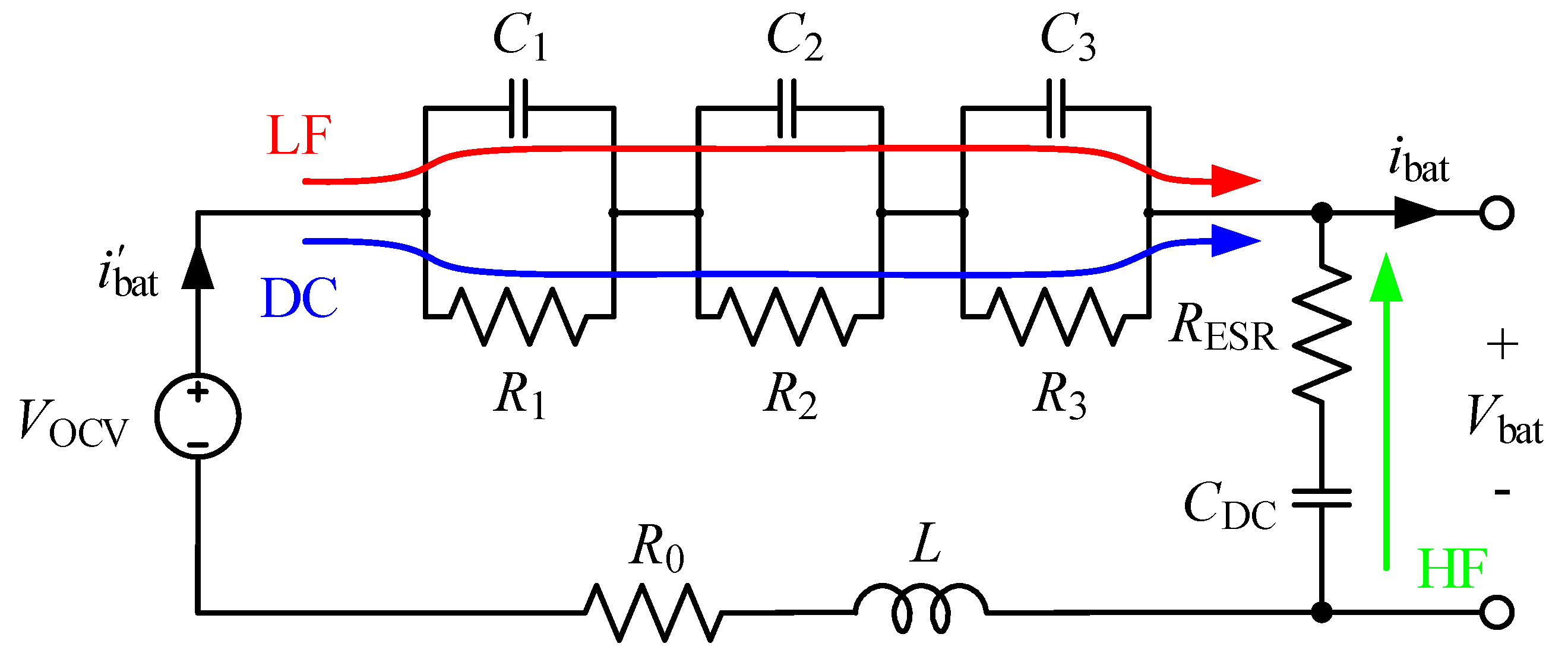
2.3. Battery Harmonics and Modeling of Battery Losses

The battery packs in a cascaded H-bridge inverter are intermittently conducting the corresponding phase current, which is illustrated in Figure 7a for the third converter module when using multilevel PWM and FSHE as depicted in Figure 4 and Figure 5, respectively. The corresponding frequency components of the battery current are depicted in Figure 7b. As already described in [13], the battery packs are subject to a large amount of low order harmonics components. The second harmonic component, for single phase converters referred to as double line frequency (DLF) pulsation [38], is dominant for both multilevel PWM and FSHE. Due to the intermittent rectification of the phase current, the fourth harmonic is notably strong pronounced as well. Comparing the distinct harmonics, multilevel PWM typically creates side band harmonics around multiples of the switching frequency f sw , whereas FSHE creates a series of low-frequency harmonics.
To properly estimate the ohmic losses of the battery system, a dynamic battery model for the entire torque-speed range of the drivetrain, covering a broad frequency range, should be chosen according to [39]. Therefore, the three-time constant Randles model, including a DC-link capacitance, as depicted in Figure 8 is chosen.
As illustrated, the DC, low-frequency (LF) and high-frequency (HF) components are conducted through different paths. The ohmic battery losses can be estimated using simulations according to
P Loss = j = 0 3 R j i R j 2 + R ESR i R ESR 2 .

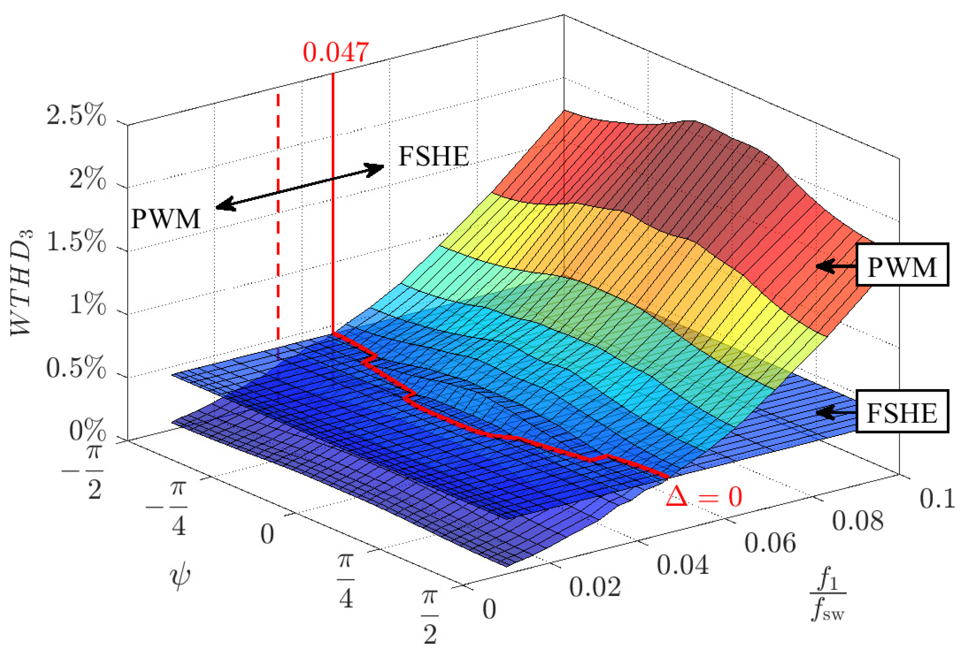
2.4. Concept of the Weighted THD (WTHD)

Besides the drivetrain losses, the torque ripple of a vehicle’s electric machine is another important performance factor. To completely assess the torque ripple, the mechanical load, including its resonant characteristics, and the slot harmonics need to be considered [40,41]. Nonetheless, when comparing different modulation techniques, the part of the torque ripple induced by the inverter’s output voltage harmonics is of foremost interest. Depending on the rotational direction (±), a voltage harmonic V ph , h with the frequency f h appears in the dq-frame as a sinusoidal oscillation with a similar magnitude and a frequency f dq , h relative to the fundamental frequency f 1 according to
f dq , h = f h ± f 1 X dq , h = 2 π f dq , h · L dq .
For example, assuming constant dq-inductance values and neglecting the stator resistance, the resulting dq-current harmonic in an interior permanent magnet machine at steady state can be expressed as
i d , h i q , h = X q , h 1 0 0 X d , h 1 · ± V h cos ( ω 1 ( h ± 1 ) t π 2 ) ± V h sin ( ω 1 ( h ± 1 ) t π 2 ) .
Consequently, the ripple torque’s magnitude induced by the voltage harmonic V ph , h becomes
T e , h ( t ) = 3 n p 2 [ ( L d L q ) i d , h i q , h + Ψ m i q , h ] .
Neglecting the induced reluctance torque ripple ( ( L d L q ) i d , h i q , h < < Ψ m i q , h ), it can be concluded that the induced torque ripple’s magnitude is proportional to the voltage harmonic’s magnitude according to
Δ T e , h ( t ) = 3 n p 2 [ Ψ m I q , h ] V ph , h .
Thus, the output current quality ( T H D I ), distorted by the converter’s voltage harmonics, is a performance factor related to the induced ripple torques [21].
The value of the Weighted Total Harmonic Distortion (WTHD), as introduced in [21], can be used to assess and compare the probable current quality of different voltage waveforms, e.g., created using different modulation techniques. To derive the concept of the WTHD, it is reasonable to start from the voltage THD expression, which can be described as
T H D V = V rms V 1 , rms 2 1 .
Without a DC component, the voltage THD expression becomes
T H D V = h = 2 V h V 1 2 .
Similar as in (14), the current THD can be expressed as
T H D I = h = 2 I h I 1 2 .
Assuming that the voltage is applied to a lossless inductive load, the current harmonics can be calculated with the help of the voltage harmonics according to
I h V h h ω 1 L with h = { 2 , 3 , 4 } .
Inserting (16) in the current THD expression given in (16), the weighted THD as a function of the voltage harmonics can be obtained according to
W T H D = 1 V 1 h = 2 V h h 2 .
Considering the phase voltage V ph of a floating three-phase system, the triplen harmonics and the common mode carrier harmonics do not create any currents. Thus, to assess the current quality, the WTHD of the line voltage waveform V ll should rather be considered according to
W T H D 3 = 1 V ll , h h = 2 V ll , h h 2 .
For a set modulation index of M = 1 , Figure 9 shows the simulated W T H D 3 using PWM relative to the ratio of the fundamental f 1 and the switching frequency f sw as well as the phase shift angle ψ , representing the phase shift of the high frequency carriers and the reference voltages.
Since the W T H D 3 using FSHE does not change with the fundamental frequency, its W T H D 3 is depicted as an equipotential surface. As can be seen, when exceeding a relative fundamental frequency of 0.047, the W T H D 3 value using PWM becomes higher than when using FSHE and, thus, the current quality ( T H D I ) or the converter induced torque ripple using FSHE should be theoretically improved for higher fundamental frequencies, e.g., high speed.

3. Simulation Case Setup and Results

To analyze the effectiveness of the two output voltage modulation techniques, multilevel PWM and FSHE, relative to the broad operating range of an electric vehicle, a reference drivetrain is simulated and the power losses are weighted using different driving cycles.
A small passenger car driven by an 84 k W rated interior permanent magnet machine with a battery capacity of about 45 k W h is considered. For the inverter model, data of an Infineon OptiMOS TM -5 Power-Transistor IAUT300N10S5N015 [42] with B V DS = 100 V, R DS , on = 1.5 mΩ, I D , nom = 300 A and T j , max = 175 °C is used. The switching losses are modeled as described in [43], while the conduction losses are modeled considering the reverse conduction of the MOSFETs similar as described in [44]. For simplicity, the junction temperature of the MOSFETs is defined as constant according to T j = T coolant = 70 °C. The battery packs are modeled based on the impedance of a reference battery cell, given in Table 1.
The chosen cylindrical 18650 high energy cell is manufactured by LG Chem. It has a nominal voltage of 3.72 V and a rated capacity of 2800 m A h, which corresponds to about 10.42 W h [45]. Each battery pack comprises a capacity of about 5 k W h consisting of 18 and 27 cells in series and parallel, respectively. Additionally, each H-bridge module is equipped with a small DC-link capacitor of about 20 m F . Since the electric machine is operated at fundamental frequencies up to almost 1 k Hz , the switching frequency, when using PWM, is set to 10 k Hz [25,46]. A full description of the modeled vehicle’s power train, including the inverter and battery modeling and their parameter extraction, can be found in [11]. As described in [11], the costs for the MLI’s semiconductor switches in comparison to a two-level IGBT inverter with a similar apparent power rating are significantly reduced from 341.54 to 121.32. The costs for the additional gate drivers are presumably increased in comparison to a two-level inverter, whereas the MLI inherently acts as a part of the battery management system and individual modules can be used as low-voltage auxiliary supplies [12,47]. Therefore, the designed reference drivetrain is a cost-effective solution in comparison to a two-level IGBT inverter with a 400 V battery system.
Matlab Simulink in combination with PLexim’s PLECS blockset package is used for all simulations. Using a fixed motor speed and the current controller described in [17], a couple of hundred steady state operating points within the motor’s torque-speed boundaries are simulated, similar as in [22]. At each steady state operating point, the drivetrain losses and the current THD are determined. Within the frame of this paper’s preliminary study, the influence of the temperature and the SOC on the battery impedance or the inverter losses are neglected.

3.1. Simulated Output Current Quality— T H D I

The obtained current T H D I for the entire torque-speed range of the vehicle’s drivetrain is depicted in Figure 10a,b for multilevel PWM and FSHE, respectively.
As expected, at low speed, e.g., low modulation indices ( M < 0.3 ), the current T H D I is significantly increased ( > > 5%) when using FSHE, since none of the low-order harmonic components can be eliminated, as shown in Figure 6b. Calculating the absolute difference of the T H D I between multilevel PWM and FSHE, as shown in Figure 11, it can be seen that FSHE achieves a slightly worse current quality around medium speed.
Nonetheless, it becomes obvious, that FSHE becomes superior at higher speeds in comparison to multilevel PWM. The boundary is emphasized in Figure 11 by the black dashed line.
Hence, the simulated boundary between multilevel PWM and FSHE with respect to the current T H D I at a modulation index of M = 1 can be roughly expressed in terms of the relative fundamental frequency ( f 1 / f sw ) as:
f 1 f sw 0.048 FSHE f 1 f sw < 0.048 multilevel PWM
This result is close to the simulated W T H D 3 boundary of 0.047, depicted in Figure 9.

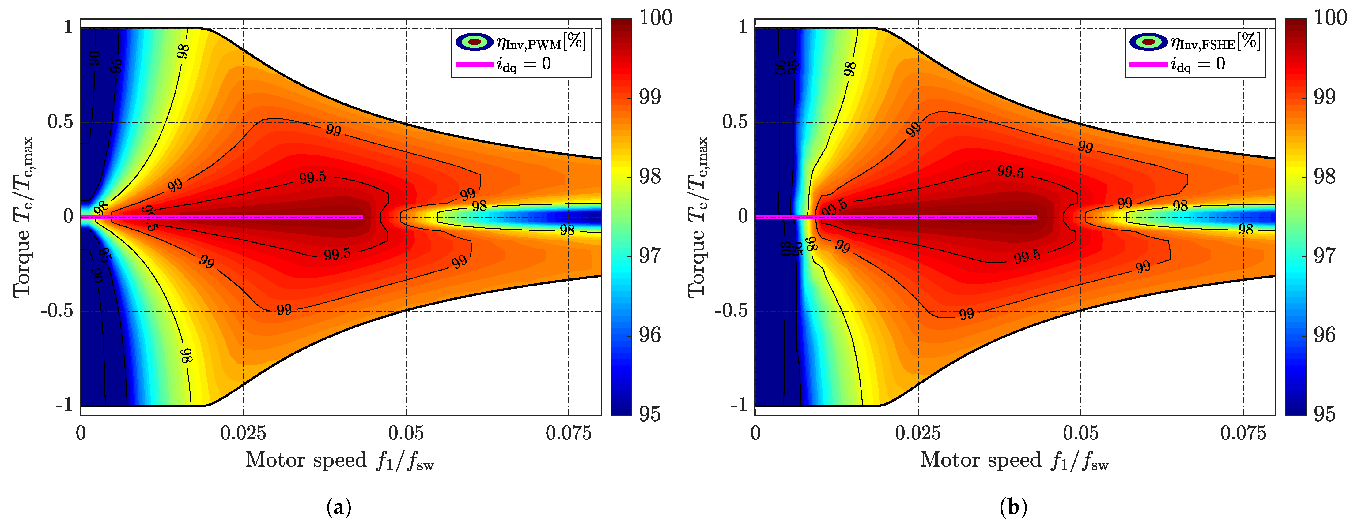
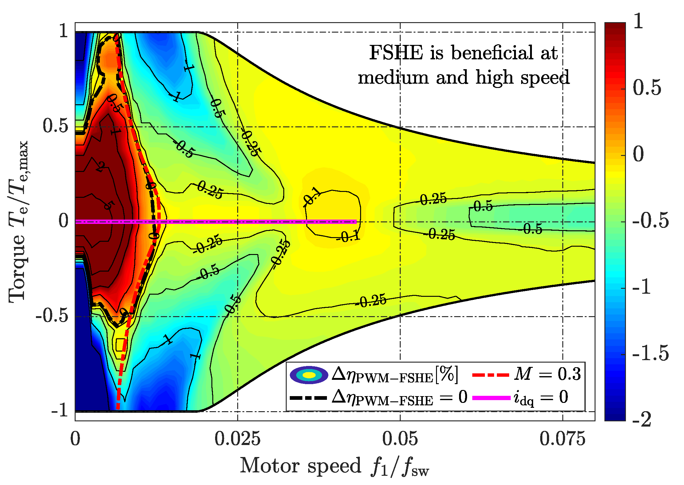
3.2. Simulated Inverter and Battery Efficiency— η Inv & η Bat

The simulated inverter efficiency for the entire torque-speed range of the drivetrain is depicted in Figure 12a,b for multilevel PWM and FSHE, respectively. At standstill and low speed, PWM is more efficient than FSHE, since the low-order current harmonics using FSHE significantly increases the conduction losses. Exceeding lower speeds, FSHE, eliminating a selection of low-order harmonics, becomes more efficient, since the conduction losses become fairly equal, while the switching losses are reduced. As can be seen, the inverter efficiency improvement using FSHE is not that obvious, since the conduction losses of the MOSFETs are dominant in comparison to the switching losses for the chosen switching frequency of 10 kHz.
The simulated battery system’s efficiency for the entire torque-speed range of the drivetrain is depicted in Figure 13a,b for multilevel PWM and FSHE, respectively. It can be seen that the battery efficiency is improved for a wide operating range, especially at low speeds. However, since FSHE cannot be applied at low speeds due to significantly increased current THD, only the medium and high speed range should be considered, showing an absolute efficiency improvement of up to 1%.
Taking a look at the absolute difference of the combined battery and inverter efficiency η Inv η Bat , as shown in Figure 14, it can be seen that FSHE achieves an improvement almost throughout the entire operating range. The zero boundary is emphasized with the black dashed line. Throughout the medium speed range, the absolute improvement of the drivetrain efficiency is up to about 1.5%. At low speed, FSHE cannot be applied due to the high current THD. Hence, the drivetrain efficiency boundary between multilevel PWM and FSHE can be roughly described as:
M 0.3 FSHE M < 0.3 multilevel PWM

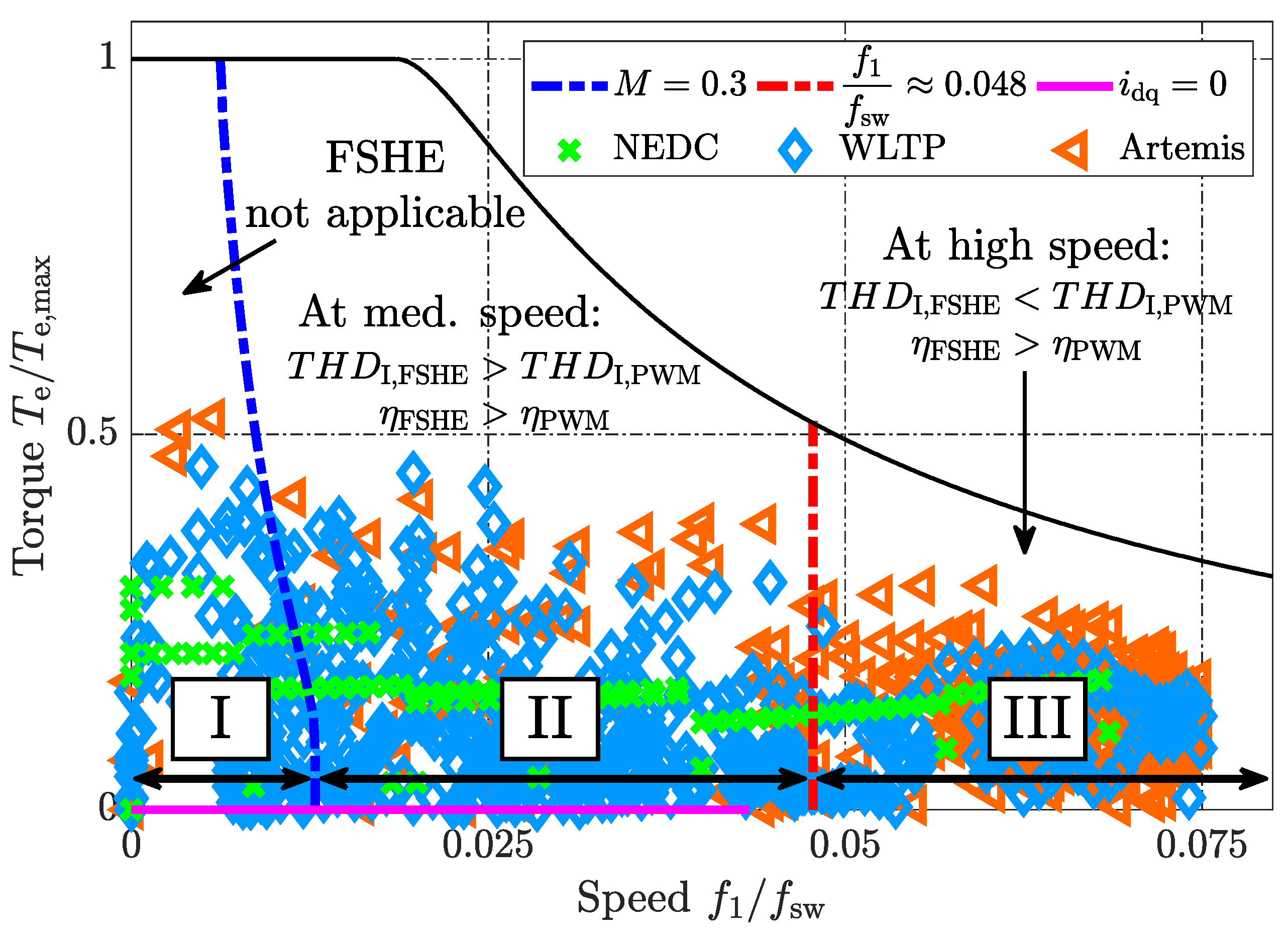
3.3. Drive Cycle Losses Using Simple Optimal Hybrid Modulation Technique—PWM-FSHE

Figure 15 depicts the beneficial operating regions using FSHE in comparison to multilevel PWM. Additionally, the operating points of the small passenger car, as described in [11], are calculated according to [22] for three different driving cycles. As seen from (19) and (20), depicted in Figure 15, it seems reasonable to operate the CHB inverter with a hybrid modulation technique, using multilevel PWM at low and FSHE at medium and high speeds. The boundary between multilevel PWM and FSHE should be selected in a manner to meet a simple optimization relative to the individual current T H D I and the drivetrain efficiency η Inv η Bat requirements according to
minimize T e T max , f 1 f sw K Eff · η Inv η Bat + K THD · T H D I subject to M 0.3
To quantify the effectiveness of the suggested hybrid technique, the energy consumption of the reference vehicle in [11] is simulated using only multilevel PWM and the suggested hybrid technique in (21) with K THD = 0 (if M 0.3 , FSHE is applied). The obtained results can be seen in Table 2, which are compared with the results of the two-level IGBT converter in [11], utilizing the FS400R07A3E3 HybridPACK TM module [48] from Infineon Technologies AG with a blocking capability of B V CES = 700 V and a nominal collector current of I C , nom = 400 A. As can be seen from the obtained results, the two-level inverter (2-L IGBT) achieves a better battery efficiency, whereas the MOSFET multilevel inverter, operated with PWM (CHB-PWM) and the suggested hybrid technique (CHB-Opt), yields a better inverter efficiency. Considering the total efficiency, the MOSFET multilevel inverter operated with only PWM achieves an absolute efficiency enhancement of 0.17% to 0.53% in comparison to the IGBT inverter. Using the suggested optimized hybrid modulation technique, the efficiency enhancement is improved even further to 0.46% to 0.85%.
When actually implementing the suggested hybrid technique, a narrow dual threshold boundary (hysteris) should be considered. In this manner, the controller would not constantly change the modulation technique when operating at or close to the defined PWM-FSHE boundary.

4. Experimental Case Setup

Due to the large number of voltage sources and the presumably small energy difference, which is typically prone to large errors, the efficiency of the battery and the inverter system is not measured. Nonetheless, to validate the effectiveness of FSHE in comparison to multilevel PWM at higher speeds, the current THD can be easily measured using a small scale setup. Since the current THD relates to the current’s RMS value, an improved current THD corresponds to reduced inverter conduction losses. Thus, if FSHE achieves a better current THD, the inverter efficiency is inherently improved as well.
Figure 16a shows one of the used IGBT H-bridge modules including one 48 V battery pack. The H-bridge modules utilize the sixpack IGBT power modules PSS15S92F6-AG/PSS15S92E6-AG ( B V CES = 400   V and I C , nom = 15   A ) from Mitsubishi Electronics [49]. Additionally, each H-bridge is equipped with a capacitor bank of 4 m F . The battery packs consists of 13 series and 4 parallel connected battery cells, resulting in a nominal voltage of about 48 V . The complete inverter setup, consisting of 6 H-bridge modules, can be seen in Figure 16b.
Just two phases, comprising 3 converter modules each, are operated with a phase shift of 120 . The used R L -load has an inductance and a resistance value of about 52 m H and 2.4 Ω , respectively. The load is connected between both phases representing a motor-load in delta connection. A dSPACE system is used to operate the gate signals of the inverter.
Figure 17 depicts the measured line voltage, including its FFT, and the line current when operating the inverter with multilevel PWM and FSHE. The battery packs are charged to about 50 V and the modulation index M is about 1. The fundamental frequency f 1 and the switching frequency f sw are chosen to be 500 Hz and 10 k Hz , respectively, to emphasize the effectiveness of FSHE at high speed. As can be seen, the voltage drop across the IGBTs and the antiparallel diodes, depending on the current direction, distorts the voltage waveform. This effect would be significantly reduced when using MOSFETs, as intended for a real application, instead of IGBTs. The FFT of the line voltage, displayed up to 150 k Hz (supraharmonic band [50,51]), indicates a reduction of possible conducted emissions. Using FSHE, the highest occurring line voltage harmonic, the 17th, is reduced by a factor of four in comparison to the highest sideband harmonic when using multilevel PWM. Further, Figure 17c shows the measured load current. Despite the reduced number of switching events, the current THD using FSHE in comparison to multilevel PWM, is reduced from 1.59% to 1.13%.
Furthermore, Figure 18 depicts the measured current THD relative to the modulation index M when operating the CHB inverter with multilevel PWM and FSHE ( f 1 = 500 Hz and f sw = 10 kHz).
Additionally, the simulated W T H D 3 is shown. Both measurement series follow the trend of each simulation. Moreover, the measured current THD difference, using FSHE in comparison to multilevel, seems enhanced. As can be seen from Figure 17c, at each switching event a displacement current [52] is triggered, which distorts the current waveform. Since multilevel PWM inherently utilizes more switching events than FSHE, the difference between the simulation and the measurements is larger. Thus, FSHE actually shows a better current quality over a wider modulation index range in comparison to multilevel PWM.

5. Conclusions

This paper has dealt with the output voltage modulation of a modular battery inverter system, based on a cascaded H-bridge converter topology, when used for vehicle propulsion. Two generally-known modulation techniques, PD-PWM and FSHE, have been considered and extensively compared when used for such an innovative drivetrain/battery architecture. To assess the effectiveness of each method relative to the torque-speed range of a small passenger vehicle, the drivetrain losses (battery and inverter losses) and the current THD have been used as benchmark parameters. Furthermore, a small-scale laboratory setup has been operated with multilevel PWM and FSHE to verify FSHE’s current THD improvement at higher speeds.
It has been seen that FSHE cannot be applied at standstill and low speed. If the modulation index M is below 0.3, FSHE causes a high current THD ( > > 5%), resulting in higher drivetrain losses in comparison to PWM. Nonetheless, exceeding a modulation index of 0.3, FSHE improves the drivetrain efficiency and at higher speeds ( f 1 f sw > 0.048 ) it even reduces the current THD in comparison to multilevel PWM. Thus, it has been concluded that it is the most beneficial to operate the CHB inverter with a hybrid output voltage modulation technique. At low speed and stand still, the drivetrain must be operated with multilevel PWM, whereas at higher speeds, FSHE should be selected. The boundary between multilevel PWM and FSHE is dependent on the modulation index M and the relative fundamental frequency f 1 f sw . It should be selected in a manner to meet an optimization relative to the individual current T H D I and drivetrain efficiency η Inv η Bat requirements. As another key-result, it has been shown that the absolute, simulated drive cycle efficiency of the modeled small passenger car has been improved by 0.29% to 0.42% when using a simple optimized hybrid technique in comparison to using only PWM. Furthermore, using a small-scale laboratory setup, FSHE’s improved performance could be verified using the measured current THD values. In addition, the measurements showed that FSHE’s waveform is less affected by the IGBT dead-times and the parasitic displacement currents, due to the reduced number of switching events.

Author Contributions

Conceptualization, A.K., M.K. and T.T.; methodology, A.K., M.K. and T.T.; software, A.K. and M.K.; validation, A.K.; formal analysis, A.K. and M.K.; investigation, A.K. and M.K.; resources, A.K. and T.T.; data curation, A.K. and M.K.; writing—original draft preparation, A.K. and M.K.; writing—review and editing, A.K. and M.K.; visualization, A.K. and M.K.; supervision, T.T.; project administration, T.T.; funding acquisition, T.T. All authors have read and agreed to the published version of the manuscript.

Funding

The financial support provided by the Swedish Energy Agency is gratefully acknowledged.

Conflicts of Interest

The authors declare no conflict of interest. The funders had no role in the design of the study; in the collection, analyses, or interpretation of data; in the writing of the manuscript, or in the decision to publish the results

References

  1. Kersten, A.; Baum, L.; Han, W.; Thiringer, T.; Bongiorno, M. Output Voltage Synthesis of a Modular Battery System based on a Cascaded H-Bridge Multilevel Inverter Topology for Vehicle Propulsion: Multilevel Pulse Width Modulation vs. Fundamental Selective Harmonic Elimination. In Proceedings of the 2020 IEEE Transportation Electrification Conference Expo (ITEC), Chicago, IL, USA, 23–26 June 2020; pp. 296–302. [Google Scholar] [CrossRef]
  2. Grunditz, E.A.; Thiringer, T. Performance Analysis of Current BEVs Based on a Comprehensive Review of Specifications. IEEE Trans. Transp. Electrif. 2016, 2, 270–289. [Google Scholar] [CrossRef]
  3. Maiser, E. Battery packaging-Technology review. AIP Conf. Proc. Am. Inst. Phys. 2014, 1597, 204–218. [Google Scholar]
  4. Arora, S.; Shen, W.; Kapoor, A. Review of mechanical design and strategic placement technique of a robust battery pack for electric vehicles. Renew. Sustain. Energy Rev. 2016, 60, 1319–1331. [Google Scholar] [CrossRef]
  5. Mareev, I.; Becker, J.; Sauer, D.U. Battery dimensioning and life cycle costs analysis for a heavy-duty truck considering the requirements of long-haul transportation. Energies 2018, 11, 55. [Google Scholar] [CrossRef] [Green Version]
  6. Mohamadi, B.; Noshahr, J.B.; Adelmanesh, B.; Shidare, E.; Kermani, M. Optimal Battery Energy Storage Sizing in Microgrids by using Artificial Flora Algorithm. In Proceedings of the 2020 IEEE International Conference on Environment and Electrical Engineering and 2020 IEEE Industrial and Commercial Power Systems Europe (EEEIC/I CPS Europe), Madrid, Spain, 9–12 June 2020; pp. 1–6. [Google Scholar] [CrossRef]
  7. Vitols, K. Efficiency of LiFePO4 battery and charger with passive balancing. In Proceedings of the 2015 IEEE 3rd Workshop on Advances in Information, Electronic and Electrical Engineering (AIEEE), Riga, Latvia, 13–14 November 2015; pp. 1–4. [Google Scholar]
  8. Wei, X.; Zhu, B. The research of vehicle power Li-ion battery pack balancing method. In Proceedings of the 2009 9th International Conference on Electronic Measurement Instruments, Beijing, China, 16–19 August 2009; pp. 498–502. [Google Scholar]
  9. Lee, W.C.; Drury, D.; Mellor, P. Comparison of passive cell balancing and active cell balancing for automotive batteries. In Proceedings of the 2011 IEEE Vehicle Power and Propulsion Conference, Chicago, IL, USA, 6–9 September 2011; pp. 1–7. [Google Scholar]
  10. Han, W.; Wik, T.; Kersten, A.; Dong, G.; Zou, C. Next-Generation Battery Management Systems: Dynamic Reconfiguration. IEEE Ind. Electron. Mag. 2020, 14, 20–31. [Google Scholar] [CrossRef]
  11. Kersten, A.; Kuder, M.; Grunditz, E.; Geng, Z.; Wikner, E.; Thiringer, T.; Weyh, T.; Eckerle, R. Inverter and Battery Drive Cycle Efficiency Comparisons of CHB and MMSP Traction Inverters for Electric Vehicles. In Proceedings of the 2019 21st European Conference on Power Electronics and Applications (EPE ’19 ECCE Europe), Genova, Italy, 3–5 September 2019; pp. 1–12. [Google Scholar]
  12. Helling, F.; Kuder, M.; Singer, A.; Schmid, S.; Weyh, T. Low Voltage Power Supply in Modular Multilevel Converter based Split Battery Systems for Electrical Vehicles. In Proceedings of the 2018 20th European Conference on Power Electronics and Applications (EPE’18 ECCE Europe), Riga, Latvia, 17–21 September 2018; pp. 1–10. [Google Scholar]
  13. Kersten, A.; Theliander, O.; Grunditz, E.A.; Thiringer, T.; Bongiorno, M. Battery Loss and Stress Mitigation in a Cascaded H-Bridge Multilevel Inverter for Vehicle Traction Applications by Filter Capacitors. IEEE Trans. Transp. Electrif. 2019, 5, 659–671. [Google Scholar] [CrossRef]
  14. Vasiladiotis, M.; Rufer, A. Balancing control actions for cascaded H-bridge converters with integrated battery energy storage. In Proceedings of the 2013 15th European Conference on Power Electronics and Applications (EPE), Lille, France, 2–6 September 2013; pp. 1–10. [Google Scholar]
  15. Kersten, A.; Oberdieck, K.; Gossmann, J.; Bubert, A.; Loewenherz, R.; Neubert, M.; Thiringer, T.; De Doncker, R. Measuring and Separating Conducted Three-Wire Emissions from a Fault-Tolerant, NPC Propulsion Inverter with a Split-Battery using Hardware Separators based on HF Transformers. IEEE Trans. Power Electron. 2020, 36, 378–390. [Google Scholar] [CrossRef]
  16. Laumen, M.; Schubert, M.; Bubert, A.; Lamprecht, A.; De Doncker, R.W. Optimized space vector modulation for DC-link balancing in three-level neutral-point-clamped inverters for electric drives. In Proceedings of the 2017 IEEE 12th International Conference on Power Electronics and Drive Systems (PEDS), Honolulu, HI, USA, 12–15 December 2017; pp. 1135–1140. [Google Scholar]
  17. Kersten, A.; Oberdieck, K.; Bubert, A.; Neubert, M.; Grunditz, E.; Thiringer, T.; De Doncker, R.W. Fault Detection and Localization for Limp Home Functionality of Three-Level NPC Inverters with Connected Neutral Point for Electric Vehicles. IEEE Trans. Transp. Electrif. 2019, 5, 416–432. [Google Scholar] [CrossRef]
  18. Chang, F.; Roemer, F.; Lienkamp, M. Influence of Current Ripples in Cascaded Multilevel Topologies on the Aging of Lithium Batteries. IEEE Trans. Power Electron. 2020, 35, 11879–11890. [Google Scholar] [CrossRef]
  19. Bessman, A.; Soares, R.; Wallmark, O.; Svens, P.; Lindbergh, G. Aging effects of AC harmonics on lithium-ion cells. J. Energy Storage 2019, 21, 741–749. [Google Scholar] [CrossRef]
  20. Brand, M.J.; Hofmann, M.H.; Schuster, S.S.; Keil, P.; Jossen, A. The Influence of Current Ripples on the Lifetime of Lithium-Ion Batteries. IEEE Trans. Veh. Technol. 2018, 67, 10438–10445. [Google Scholar] [CrossRef]
  21. Holmes, D.G.; Lipo, T.A. Pulse width Modulation for Power Converters: Principles and Practice; John Wiley & Sons: Hoboken, NJ, USA, 2003; Volume 18. [Google Scholar]
  22. Kersten, A.; Grunditz, E.; Thiringer, T. Efficiency of Active Three-Level and Five-Level NPC Inverters Compared to a Two-Level Inverter in a Vehicle. In Proceedings of the 2018 20th European Conference on Power Electronics and Applications (EPE’18 ECCE Europe), Riga, Latvia, 17–21 September 2018; pp. 1–9. [Google Scholar]
  23. Korte, C.; Specht, E.; Hiller, M.; Goetz, S. Efficiency evaluation of MMSPC/CHB topologies for automotive applications. In Proceedings of the 2017 IEEE 12th International Conference on Power Electronics and Drive Systems (PEDS), Honolulu, HI, USA, 12–15 December 2017; pp. 324–330. [Google Scholar]
  24. Chang, F.; Ilina, O.; Lienkamp, M.; Voss, L. Improving the Overall Efficiency of Automotive Inverters Using a Multilevel Converter Composed of Low Voltage Si mosfets. IEEE Trans. Power Electron. 2019, 34, 3586–3602. [Google Scholar] [CrossRef]
  25. Sharifabadi, K.; Harnefors, L.; Nee, H.P.; Norrga, S.; Teodorescu, R. Design, Control, and Application of Modular Multilevel Converters for HVDC Transmission Systems; John Wiley & Sons: Hoboken, NJ, USA, 2016. [Google Scholar]
  26. Du, Z.; Tolbert, L.M.; Ozpineci, B.; Chiasson, J.N. Fundamental Frequency Switching Strategies of a Seven-Level Hybrid Cascaded H-Bridge Multilevel Inverter. IEEE Trans. Power Electron. 2009, 24, 25–33. [Google Scholar] [CrossRef] [Green Version]
  27. Fei, W.; Du, X.; Wu, B. A Generalized Half-Wave Symmetry SHE-PWM Formulation for Multilevel Voltage Inverters. IEEE Trans. Ind. Electron. 2010, 57, 3030–3038. [Google Scholar] [CrossRef]
  28. Moeini, A.; Hui, Z.; Wang, S. High efficiency, hybrid Selective Harmonic Elimination phase-shift PWM technique for Cascaded H-Bridge inverters to improve dynamic response and operate in complete normal modulation indices. In Proceedings of the 2016 IEEE Applied Power Electronics Conference and Exposition (APEC), Long Beach, CA, USA, 20–24 March 2016; pp. 2019–2026. [Google Scholar] [CrossRef]
  29. Lesnicar, A.; Marquardt, R. An innovative modular multilevel converter topology suitable for a wide power range. In Proceedings of the 2003 IEEE Bologna Power Tech Conference Proceedings, Bologna, Italy, 23–26 June 2003. [Google Scholar]
  30. Behrouzian, E.; Bongiorno, M.; Teodorescu, R. Impact of Switching Harmonics on Capacitor Cells Balancing in Phase-Shifted PWM-Based Cascaded H-Bridge STATCOM. IEEE Trans. Power Electron. 2017, 32, 815–824. [Google Scholar] [CrossRef]
  31. Pulikanti, S.R.; Agelidis, V.G. Hybrid Flying-Capacitor-Based Active-Neutral-Point-Clamped Five-Level Converter Operated With SHE-PWM. IEEE Trans. Ind. Electron. 2011, 58, 4643–4653. [Google Scholar] [CrossRef]
  32. Haw, L.K.; Dahidah, M.S.A.; Almurib, H.A.F. SHE–PWM Cascaded Multilevel Inverter With Adjustable DC Voltage Levels Control for STATCOM Applications. IEEE Trans. Power Electron. 2014, 29, 6433–6444. [Google Scholar] [CrossRef]
  33. Law, K.H.; Dahidah, M.S.A.; Konstantinou, G.S.; Agelidis, V.G. SHE-PWM cascaded multilevel converter with adjustable DC sources control for STATCOM applications. In Proceedings of the 7th International Power Electronics and Motion Control Conference, Harbin, China, 2–5 June 2012; Volume 1, pp. 330–334. [Google Scholar] [CrossRef]
  34. Tolbert, L.A.; Peng, F.Z.; Cunnyngham, T.; Chiasson, J.N. Charge balance control schemes for cascade multilevel converter in hybrid electric vehicles. IEEE Trans. Ind. Electron. 2002, 49, 1058–1064. [Google Scholar] [CrossRef] [Green Version]
  35. Josefsson, O.; Thiringer, T.; Lundmark, S.; Zelaya, H. Evaluation and comparison of a two-level and a multilevel inverter for an EV using a modulized battery topology. In Proceedings of the IECON 2012—38th Annual Conference on IEEE Industrial Electronics Society, Montreal, QC, Canada, 25–28 October 2012; pp. 2949–2956. [Google Scholar]
  36. Josefsson, O.; Lindskog, A.; Lundmark, S.; Thiringer, T. Assessment of a Multilevel Converter for a PHEV charge and traction application. In Proceedings of the The XIX International Conference on Electrical Machines—ICEM 2010, Rome, Italy, 6–8 September 2010; pp. 1–6. [Google Scholar] [CrossRef]
  37. Altaf, F.; Egardt, B.; Johannesson Mårdh, L. Load Management of Modular Battery Using Model Predictive Control: Thermal and State-of-Charge Balancing. IEEE Trans. Control. Syst. Technol. 2017, 25, 47–62. [Google Scholar] [CrossRef] [Green Version]
  38. Zhao, H.; Shen, Y.; Ying, W.; Ghosh, S.S.; Ahmed, M.R.; Long, T. A Single- and Three-Phase Grid Compatible Converter for Electric Vehicle On-Board Chargers. IEEE Trans. Power Electron. 2020, 35, 7545–7562. [Google Scholar] [CrossRef]
  39. Theliander, O.; Kersten, A.; Kuder, M.; Han, W.; Grunditz, E.A.; Thiringer, T. Battery Modeling and Parameter Extraction for Drive Cycle Loss Evaluation of a Modular Battery System for Vehicles Based on a Cascaded H-Bridge Multilevel Inverter. IEEE Trans. Ind. Appl. 2020, 56, 6968–6977. [Google Scholar] [CrossRef]
  40. Fukuda, S.; Suzuki, K. Using harmonic distortion determining factor for harmonic evaluation of carrier-based PWM methods. In Proceedings of the IAS ’97. Conference Record of the 1997 IEEE Industry Applications Conference Thirty-Second IAS Annual Meeting, New Orleans, LA, USA, 5–9 October 1997; Volume 2, pp. 1534–1541. [Google Scholar] [CrossRef]
  41. Zhang, D.; Liu, T.; Zhao, H.; Wu, T. An Analytical Iron Loss Calculation Model of Inverter-Fed Induction Motors Considering Supply and Slot Harmonics. IEEE Trans. Ind. Electron. 2019, 66, 9194–9204. [Google Scholar] [CrossRef]
  42. Infineon Technologies AG. Datasheet: OptiMOSTM Power-MOSFET IAUT300N10S5N015. Available online: https://www.infineon.com/dgdl/Infineon-IAUT300N10S5N015-DS-v01_00-EN.pdf?fileId=5546d4625ee5d4cd015f2469d7203245 (accessed on 26 July 2019).
  43. Graovac, D.; Purschel, M.; Kiep, A. MOSFET power losses calculation using the data-sheet parameters. Infineon Appl. Note 2006, 1, 1–23. [Google Scholar]
  44. Acquaviva, A.; Rodionov, A.; Kersten, A.; Thiringer, T.; Liu, Y. Analytical Conduction Loss Calculation of a MOSFET Three-Phase Inverter Accounting for the Reverse Conduction and the Blanking Time. IEEE Trans. Ind. Electron. 2020. [Google Scholar] [CrossRef]
  45. LG Chem. Product Description: ICR18650 C2 2800mAh. Available online: https://datasheetspdf.com/pdf-file/861571/LG/ICR18650-C2/1 (accessed on 26 July 2019).
  46. Harnefors, L. Control of Variable-Speed Drives; Applied Signal Processing and Control, Department of Electronics, Mälardalen University: Västerås, Sweden, 2002. [Google Scholar]
  47. Kuder, M.; Schneider, J.; Kersten, A.; Thiringer, T.; Eckerle, R.; Weyh, T. Battery Modular Multilevel Management (BM3) Converter applied at Battery Cell Level for Electric Vehicles and Energy Storages. In Proceedings of the PCIM Europe Digital Days 2020, International Exhibition and Conference for Power Electronics, Intelligent Motion, Renewable Energy and Energy Management, Berlin, Germany, 7–8 July 2020; pp. 1–8. [Google Scholar]
  48. Infineon Technologies AG. Datasheet: HybridPACKTM IGBT Module FS400R07A3E3. Available online: https://www.infineon.com/dgdl/Infineon-FS400R07A3E3-DS-v03_00-EN.pdf?fileId=5546d46262b31d2e016301933f7933a6 (accessed on 28 July 2019).
  49. Mitsubishi Electric Corporation. Datasheet: Power Module PSS15S92F6- AG/PSS15S92E6-AG. Available online: https://www.mitsubishielectric-mesh.com/products/pdf/PSS15S92F6-AG_N.pdf (accessed on 28 July 2019).
  50. Grevener, A.; Meyer, J.; Rönnberg, S.; Bollen, M.; Myrzik, J. Survey of supraharmonic emission of household appliances. CIRED Open Access Proc. J. 2017, 2017, 870–874. [Google Scholar] [CrossRef]
  51. Noshahr, J.B.; Kermani, M.; Bagheri, M. The Behavior of Capacitance Component of Loads in Frequency Range 2–150 kHz (Supra-Harmonic). In Proceedings of the 2019 IEEE International Conference on Environment and Electrical Engineering and 2019 IEEE Industrial and Commercial Power Systems Europe (EEEIC/I CPS Europe), Genova, Italy, 11–14 June 2019; pp. 1–5. [Google Scholar] [CrossRef]
  52. Tang, Y.; Wang, B.; Chen, Y. Mechanism and Model Analysis of IGBT Displacement Current. In Proceedings of the 2020 3rd International Conference on Advanced Electronic Materials, Computers and Software Engineering (AEMCSE), Shenzhen, China, 24–26 April 2020; pp. 778–782. [Google Scholar]
Figure 1. (a) Overview of a generic battery pack utilizing passive balancing and (b) modular battery system consisting of small, generic battery packs.
Energies 14 01424 g001
Figure 2. Valid switching combinations of each individual H-bridge converter. In (a,b) the battery module is bypassed. In (c,d) the battery module is inserted in forward and reverse direction, respectively.
Energies 14 01424 g002
Figure 3. Topology of a seven-level CHB inverter forming a modular battery system used for variable speed drive applications such as vehicle propulsion.
Energies 14 01424 g003
Figure 4. Output voltage modulation using PD-PWM for M = 0.9 and f 1 / f sw = 0.04 .
Energies 14 01424 g004
Figure 5. Output voltage modulation using FSHE for M = 0.9 .
Energies 14 01424 g005
Figure 6. (a) Optimized pulse transition angles and (b) resulting output voltage components.
Energies 14 01424 g006
Figure 7. (a) Drained battery currents when using multilevel PWM and FSHE according to Figure 4 and Figure 5; (b) Corresponding harmonic components.
Energies 14 01424 g007
Figure 8. Randles model of a battery pack, using three time constants, including DC capacitor.
Energies 14 01424 g008
Figure 9. W T H D 3 boundary between multilevel PWM and FSHE for a seven-level inverter operated at a modulation index M = 1 .
Energies 14 01424 g009
Figure 10. Simulated current THDI for the entire drivetrain operating range for (a) multilevel PWM and (b) FSHE.
Energies 14 01424 g010
Figure 11. Obtained simulated, absolute difference in current T H D I between multilevel PWM and FSHE, Δ T H D I , PWM FSHE .
Energies 14 01424 g011
Figure 12. Simulated inverter efficiency ηInv for the entire drivetrain operating range for (a) multilevel PWM and (b) FSHE.
Energies 14 01424 g012
Figure 13. Simulated battery efficiency ηBat for the entire drivetrain operating range for (a) multilevel PWM and (b) FSHE.
Energies 14 01424 g013
Figure 14. Obtained simulated, absolute difference in combined inverter and battery efficiency η Inv η Bat between multilevel PWM and FSHE, Δ η PWM FSHE .
Energies 14 01424 g014
Figure 15. Obtained beneficial operating regions for multilevel PWM and FSHE relative to the normalized torque and relative fundamental frequency considering the current T H D I and the drivetrain efficiency η = η Inv η Bat .
Energies 14 01424 g015
Figure 16. (a) H-bridge module with 48 V battery pack; (b) Small-scale CHB inverter setup, including battery packs, with control and measurement equipment.
Energies 14 01424 g016
Figure 17. Measured (a) output voltage waveforms; including their (b) harmonic components; and (c) line current when operating the CHB inverter with multilevel PWM and FSHE for a modulation index of M ≈ 1 (f1 = 500 Hz and fsw = 10 kHz).
Energies 14 01424 g017
Figure 18. Measured current THD relative to the modulation index M and simulated W T H D 3 when operating the CHB inverter with multilevel PWM and FSHE ( f 1 = 500 Hz and f sw = 10 kHz).
Energies 14 01424 g018
Table 1. Battery cell parameters of LG Chem CR18650 C2 2800 m A h.
R 0 [m Ω ] R 1 [m Ω ] R 2 [m Ω ] R 3 [m Ω ] C 1 [mF] C 2 [mF] C 3 [F]L [nH]
41.535.027.323.2375.44339.53.625590.8
Table 2. Drive cycle evaluation.
2-L IGBT 1 CHB-PWMCHB-Opt
(a) WLTP—Electrical road load E Load = 2.76 kWh
E Loss , Inv [ W h] 70.6 43.5 39.5
E Loss , Bat [ W h] 98.3 118.9 110.0
η Inv [%] 97.51 98.45 98.59
η Bat [%] 96.64 95.93 96.22
η Tot [%] 94.23 94.44 94.86
(b) Artemis 130—Electrical road load E Load = 4.93 kWh
E Loss , Inv [ W h] 102.2 78.0 70.8
E Loss , Bat [ W h] 212.4 227.0 218.4
η Inv [%] 97.97 98.44 98.58
η Bat [%] 95.95 95.66 95.82
η Tot [%] 94.00 94.17 94.46
(c) NEDC—Electrical road load E Load = 1.11 kWh
E Loss , Inv [ W h] 31.5 17.1 15.6
E Loss , Bat [ W h] 32.6 40.2 37.8
η Inv [%] 97.24 98.48 98.61
η Bat [%] 97.25 95.56 96.75
η Tot [%] 94.56 95.09 95.41
1 Results are taken from [11].
Publisher’s Note: MDPI stays neutral with regard to jurisdictional claims in published maps and institutional affiliations.

