
Elevator Regenerative Energy Applications with Ultracapacitor and Battery Energy Storage Systems in Complex Buildings


Abstract
:1. Introduction
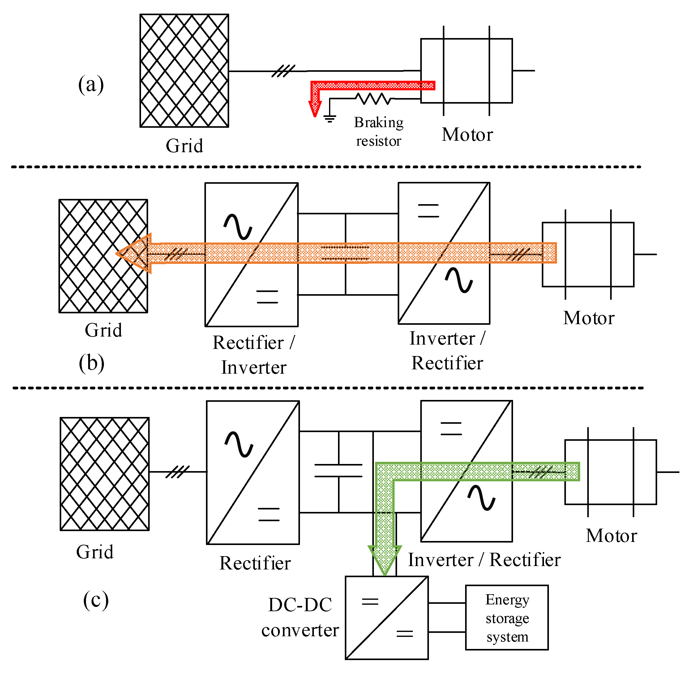
- ➢
- Case a: Dissipate regenerative energy in the resistor bank (conventional elevators).
- ➢
- Case b: Return the regenerated energy to the main grid through a backup converter.
- ➢
- Case c: Apply energy storage systems (ESSs) to utilize the regenerated energy for the elevator’s motor operation or other issues.
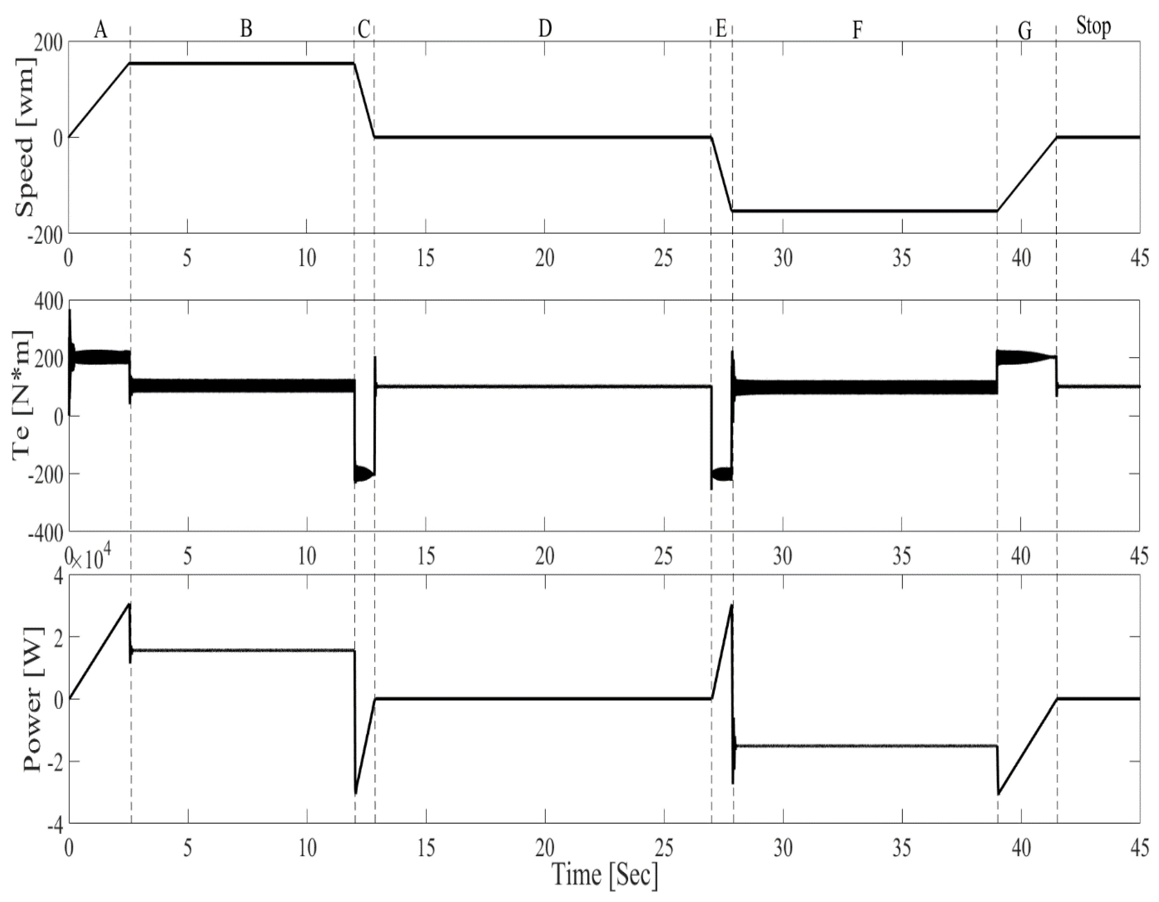
2. Elevator Operation
- -
- Motoring mode: This means that the motor is applying force and torque to lift, which is the heavy side of the balance system (e.g., raising the full load cabin).
- -
- Generating mode: For this mode, the motor does not generate positive torque, but the system shifts with its weight (e.g., lowering the full load cabin).
3. Elevator Parameters Characteristics
- Supply the motor with frequency ω, based on Equations (2) and (3) following the formula: .
- If λqr = 0 then λ = λdr, which must be kept constant by the control system so that the changes in magnetic flux are zero.
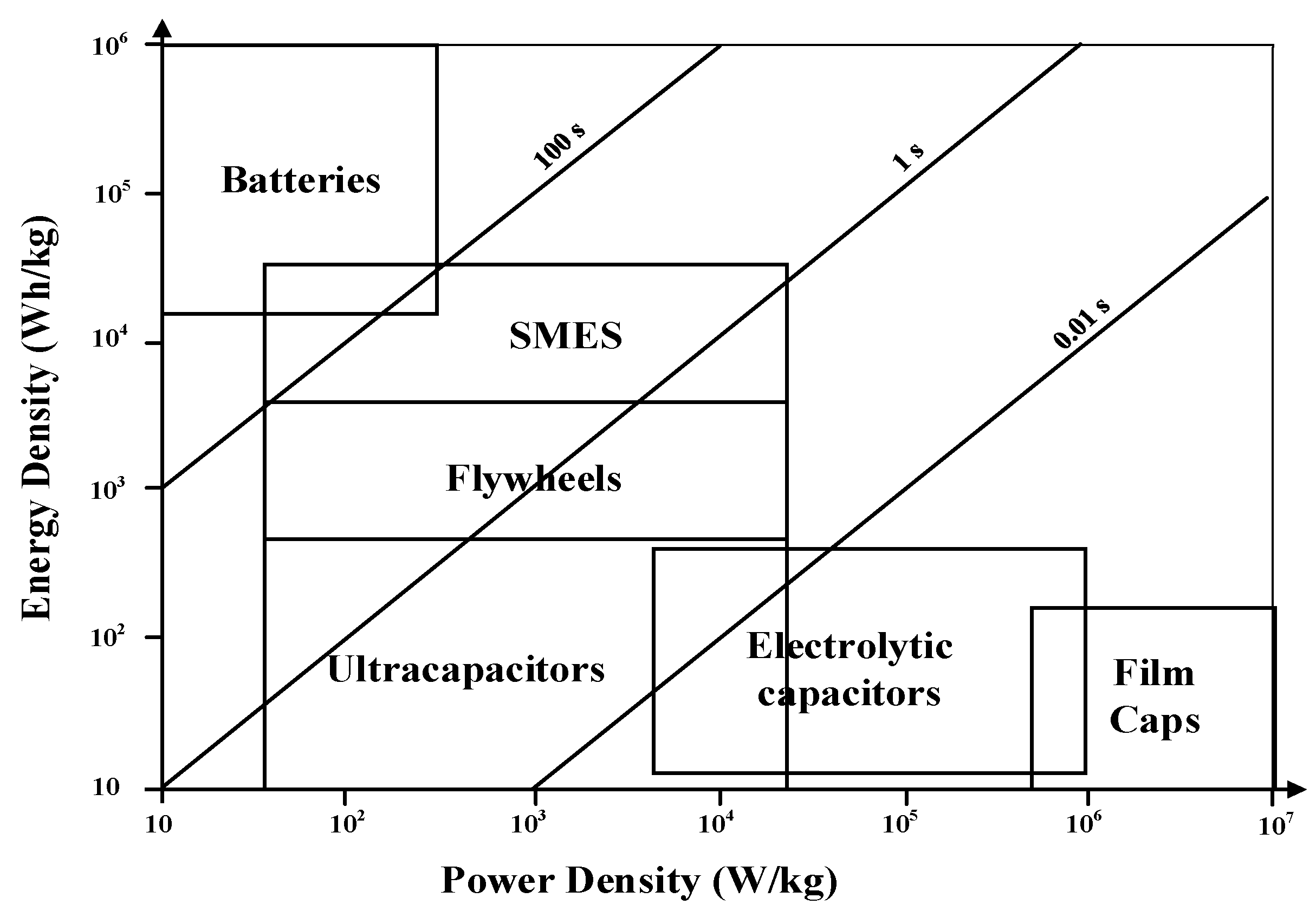
4. ESSs Selection for Elevators
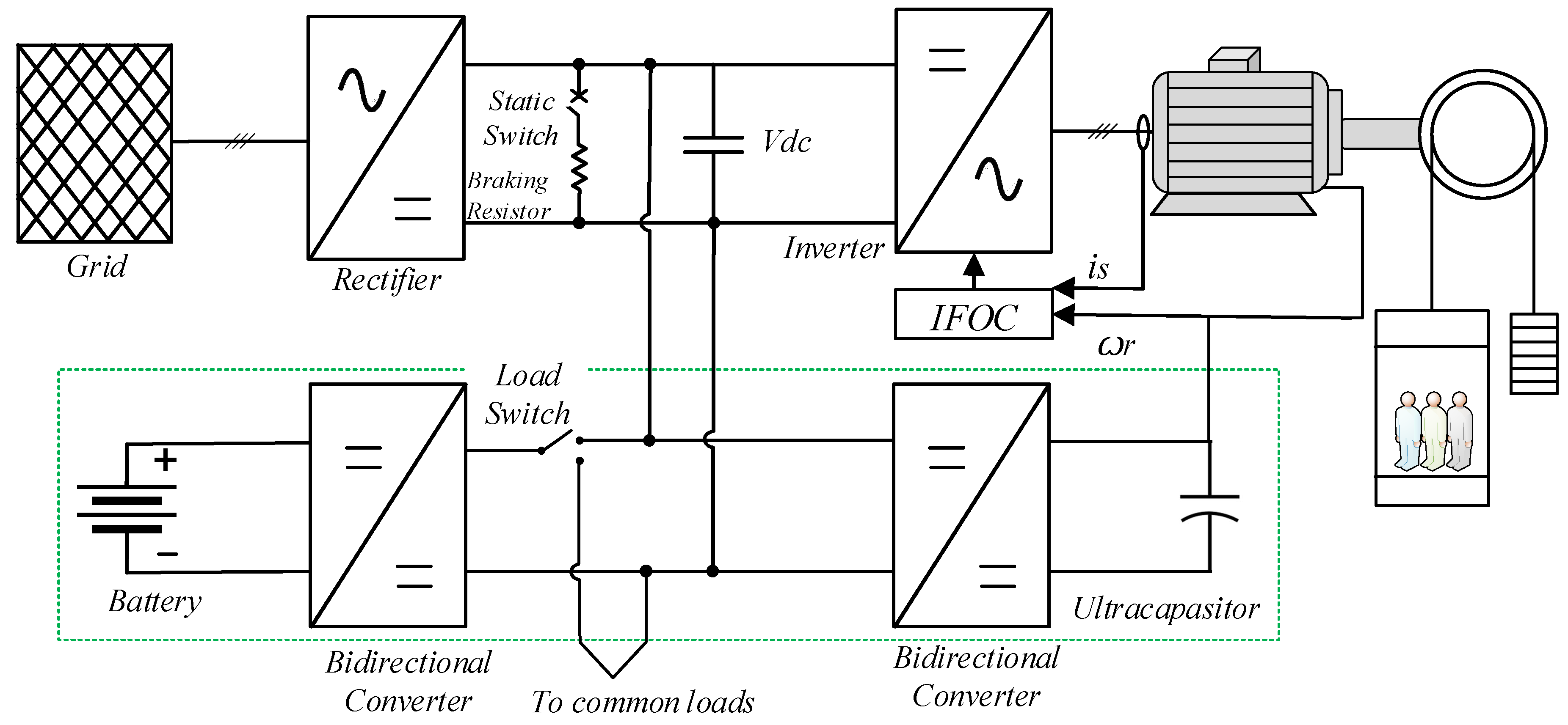
5. Control Strategies for the Case Study
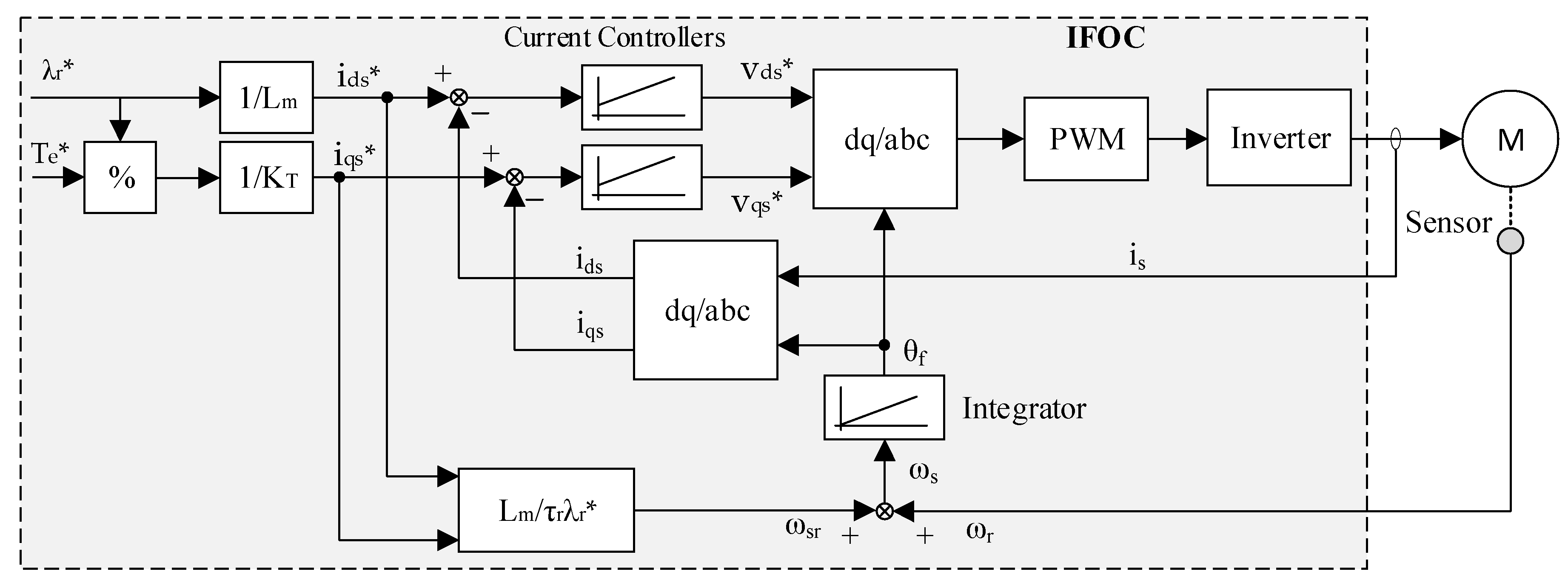
5.1. IFOC Strategy
5.2. HESS Control Strategy
- -
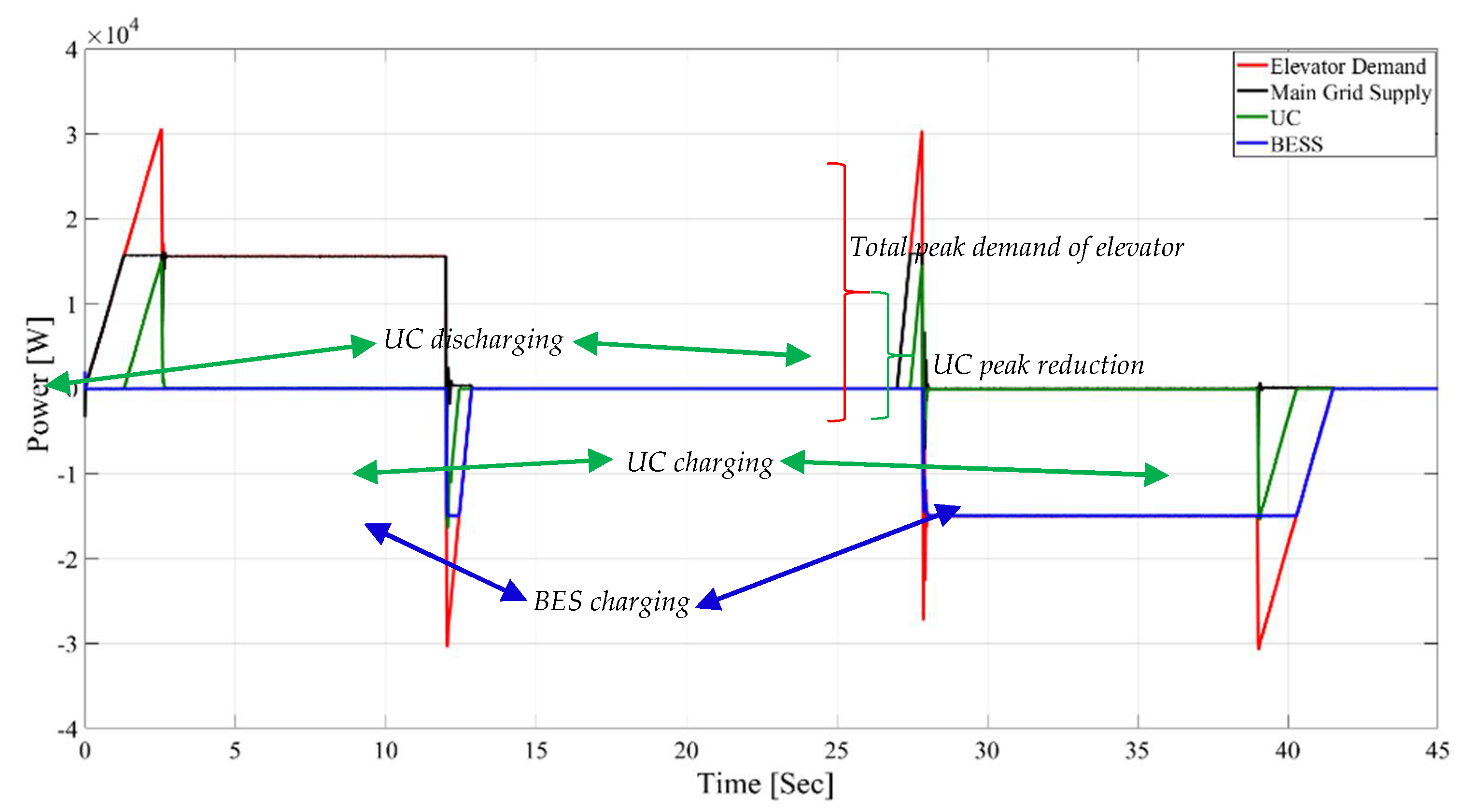
- Mode A: According to Figure 7a, when the system is faced with a high load demand, the BES is the first ESS to discharge. UCES will discharge if the BES current reaches a threshold current (IBES, th1). However, in charging mode, which happens in the case of a low load demand, both ESSs charge together and at the same time. UCES charging current was dynamically obtained according to BES charging current.
- -
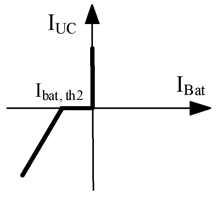
- Mode B: As is shown in Figure 7b, both UCES and BES discharge at the same time in the case of high-power demand. Nevertheless, the BES receives its charge first and when its charging current reaches another threshold (IBES, th2), the UCES begins to charge. Again, the UC current was determined based on the BES current (see Figure 8).
- -
- Mode C: Based on Figure 7c, this mode is composed of modes A and B. When the load demand is high, the BES discharges first, and UCES discharges after the BES discharging current reaches IBES, th1. On the opposite side, in the case of low load demand, the BES is charged first and the UCES starts to charge when the BES charging current reaches IBES, th2.
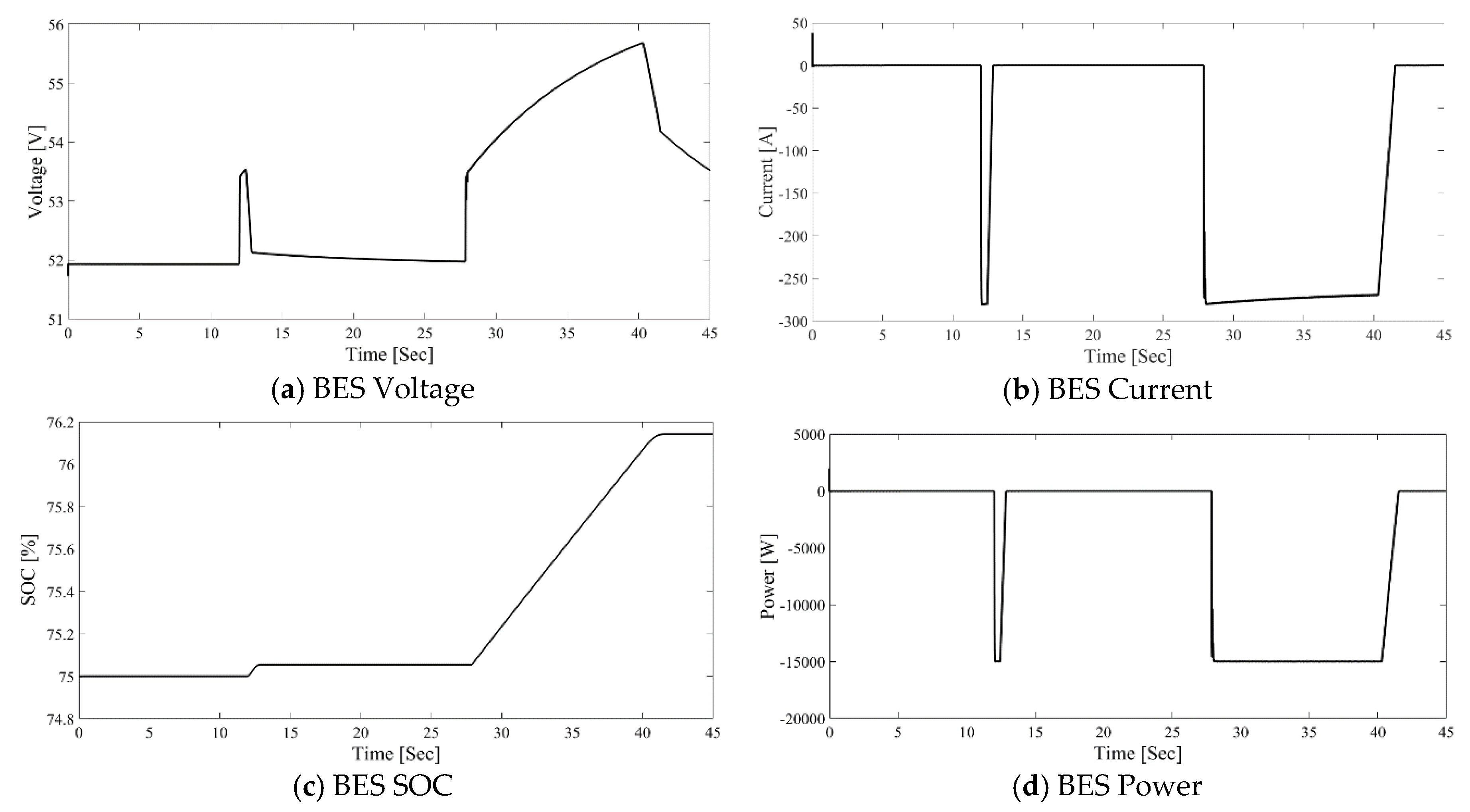
5.2.1. BES Control Strategy
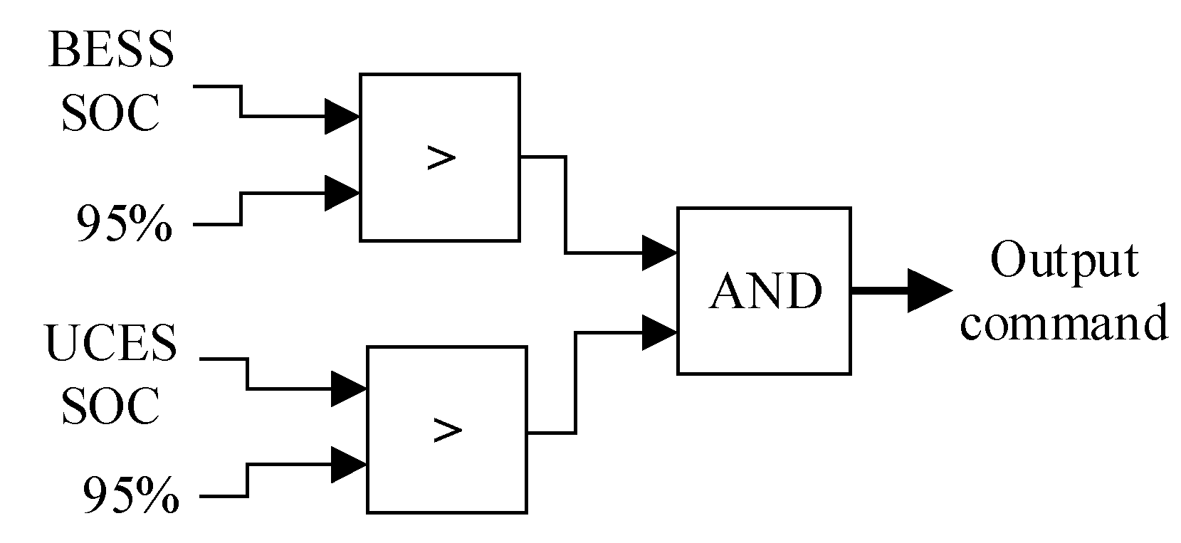
5.2.2. UCES Control Strategy
5.3. Braking Chopper Control Strategy
6. UCES and BES Sizing and Cost Evaluation
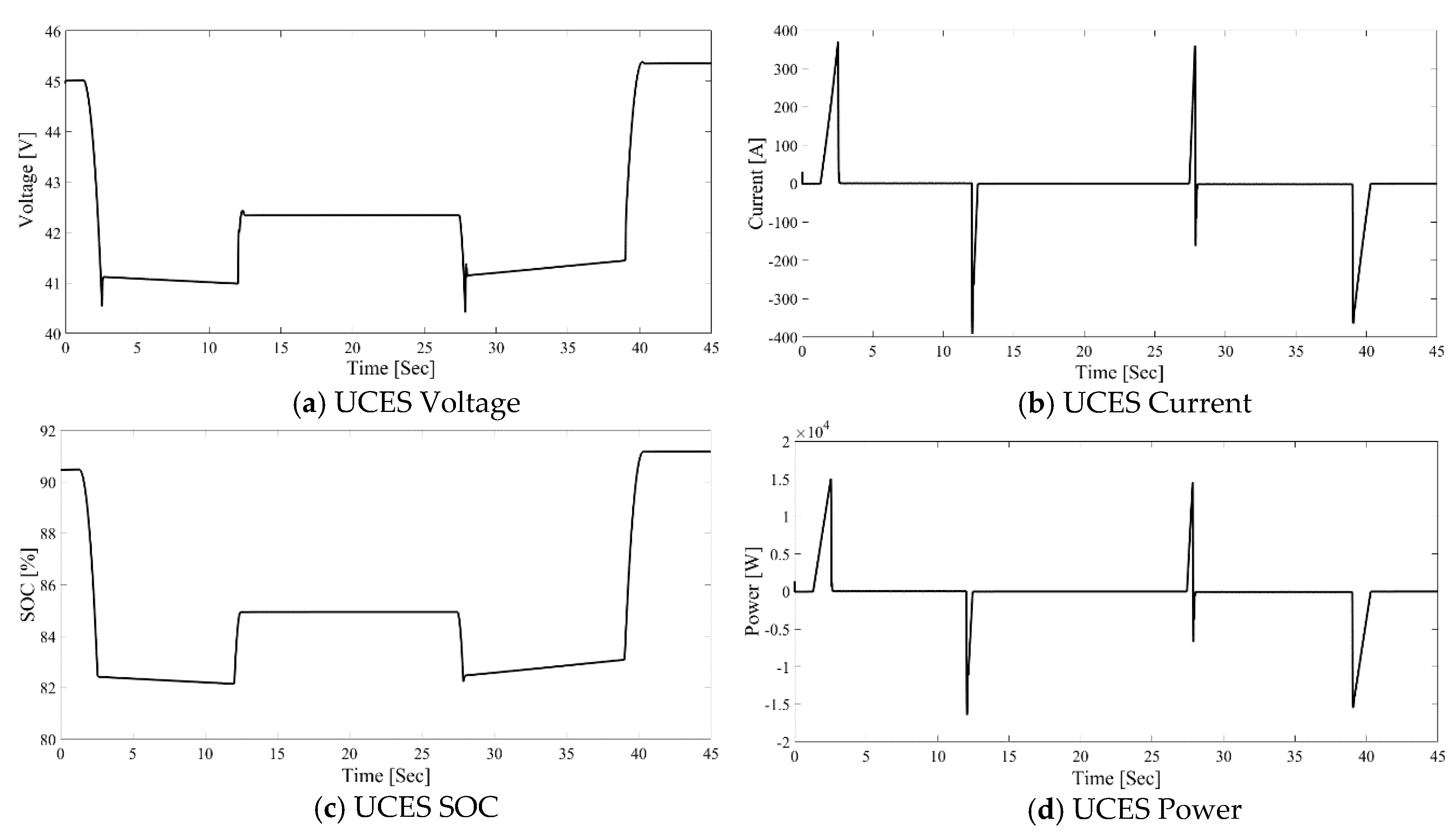
7. Results
8. Conclusions
Author Contributions
Funding
Institutional Review Board Statement
Informed Consent Statement
Data Availability Statement
Conflicts of Interest
Abbreviations
| BES | Battery Energy Storage |
| FOC | Field Oriented Control |
| FES | Flywheel Energy Storage |
| HESS | Hybrid Energy Storage System |
| IFOC | Indirect Field Oriented Control |
| SCADA | Supervisory Control and Data Acquisition |
| SOC | State of Charge |
| UCES | Ultracapacitor Energy Storage |
References
- Cao, X.; Dai, X.; Liu, J. Building energy-consumption status worldwide and the state-of-the-art technologies for zero-energy buildings during the past decade. Energy Build. 2016, 128, 198–213. [Google Scholar] [CrossRef]
- Goudarzi, H.; Mostafaeipour, A. Energy saving evaluation of passive systems for residential buildings in hot and dry regions. Renew. Sustain. Energy Rev. 2017, 68, 432–446. [Google Scholar] [CrossRef]
- Huang, H.; Chen, L.; Hu, E. A new model predictive control scheme for energy and cost savings in commercial buildings: An airport terminal building case study. Build. Environ. 2015, 89, 203–216. [Google Scholar] [CrossRef]
- Yoon, J.H.; Bladick, R.; Novoselac, A. Demand response for residential buildings based on dynamic price of electricity. Energy Build. 2014, 80, 531–541. [Google Scholar] [CrossRef]
- Alfieri, S.; Piccini, S.; Kermani, M. Feasibility study of Nearly Zero Energy Building in a real Microgrid case study. In Proceedings of the 2019 IEEE International Conference on Environment and Electrical Engineering and 2019 IEEE Industrial and Commercial Power Systems Europe (EEEIC/I&CPS Europe) IEEE, Genoa, Italy, 11–14 June 2019; pp. 1–6. [Google Scholar]
- Kermani, M.; Adelmanesh, B.; Shirdare, E.; Sima, C.A.; Carnì, D.L.; Martirano, L. Intelligent energy management based on SCADA system in a real Microgrid for smart building applications. Renew. Energy 2021, 171, 1115–1127. [Google Scholar] [CrossRef]
- Martirano, L.; Rotondo, S.; Kermani, M.; Massarella, F.; Gravina, R. Power Sharing Model for Energy Communities of Buildings. IEEE Trans. Ind. Appl. 2021, 57, 170–178. [Google Scholar] [CrossRef]
- Kermani, M.; Carnì, D.L.; Rotondo, S.; Paolillo, A.; Manzo, F.; Martirano, L. A Nearly Zero-Energy Microgrid Testbed Laboratory: Centralized Control Strategy Based on SCADA System. Energies 2020, 13, 2106. [Google Scholar] [CrossRef]
- Nipkow, J.; Schalcher, M. Energy consumption and efficiency potentials of lifts. Hospitals 2006, 2, 3. [Google Scholar]
- Jabbour, N.; Mademlis, C. Improved Control Strategy of a Supercapacitor-Based Energy Recovery System for Elevator Applications. IEEE Trans. Power Electron. 2016, 31, 1. [Google Scholar] [CrossRef]
- Rufer, A.; Barrade, P. A supercapacitor-based energy-storage system for elevators with a soft commutated inter-face. IEEE Trans. Ind. Appl. 2002, 38, 1151–1159. [Google Scholar] [CrossRef]
- Kafalis, K.; Karlis, A.D. Comparison of flywheels and supercapacitors for energy saving in elevators. In Proceedings of the 2016 IEEE Industry Applications Society Annual Meeting, IEEE, Portland, OR, USA, 2–6 October 2016; pp. 1–8. [Google Scholar]
- Pham, T.H.; Prodan, I.; Genon-Catalot, D.; Lefevre, L. Efficient energy management for an elevator system under a constrained optimization framework. In Proceedings of the 2015 19th International Conference on System Theory, Control and Computing (ICSTCC), Cheile Gradistei, Romania, 14–16 October 2015; pp. 613–618. [Google Scholar]
- Liu, H.-P.; Liu, K.; Sun, B.-N. Analysis of energy management strategy for energy-storage type elevator based on supercapacitor. In Proceedings of the 2017 11th IEEE International Conference on Compatibility, Power Electronics and Power Engineering (CPE-POWERENG), Cadiz, Spain, 4–6 April 2017; pp. 175–180. [Google Scholar]
- Kubade, P.; Umathe, S.K. Enhancing an elevator efficiency by using supercapacitor. In Proceedings of the 2017 Third Inter-national Conference on Advances in Electrical, Electronics, Information, Communication, and Bio-Informatics (AEEICB), Chennai, India, 27–28 February 2017; pp. 502–505. [Google Scholar]
- Jabbour, N.; Mademlis, C. Supercapacitor-Based Energy Recovery System with Improved Power Control and Energy Management for Elevator Applications. IEEE Trans. Power Electron. 2017, 32, 9389–9399. [Google Scholar] [CrossRef]
- Ferreira, F.J.; Almeida, A. Reducing Energy Costs in Electric-Motor-Driven Systems: Savings Through Output Power Reduction and Energy Regeneration. IEEE Ind. Appl. Mag. 2017, 24, 84–97. [Google Scholar] [CrossRef]
- Zeb, K.; Ali, Z.; Saleem, K.; Uddin, W.; Javed, M.A.; Christofides, N. Indirect field-oriented control of induction motor drive based on adaptive fuzzy logic controller. Electr. Eng. 2016, 99, 803–815. [Google Scholar] [CrossRef]
- Kermani, M.; Parise, G.; Martirano, L.; Parise, L.; Chavdarian, B. Power Balancing in STS group Cranes with Flywheel Energy Storage based on DSM Strategy. In Proceedings of the 2018 IEEE 59th International Scientific Conference on Power and Electrical Engineering of Riga Technical University (RTUCON), Riga, Latvia, 12–14 November 2018; pp. 1–5. [Google Scholar]
- Kermani, M.; Parise, G.; Martirano, L.; Parise, L.; Chavdarian, B. Optimization of Peak Load Shaving in STS Group Cranes Based on PSO Algorithm. In Proceedings of the 2018 IEEE International Conference on Environment and Electrical Engineering and 2018 IEEE Industrial and Commercial Power Systems Europe (EEEIC/I&CPS Europe), Palermo, Italy, 11–14 June 2018; pp. 1–5. [Google Scholar]
- Uddin, M.; Romlie, M.F.; Abdullah, M.F.; Abd Halim, S.; Kwang, T.C. A review on peak load shaving strategies. Renew. Sustain. Energy Rev. 2018, 82, 3323–3332. [Google Scholar] [CrossRef]
- Gür, T.M. Review of electrical energy storage technologies, materials and systems: Challenges and prospects for large-scale grid storage. Energy Environ. Sci. 2018, 11, 2696–2767. [Google Scholar] [CrossRef]
- Grbovic, P.J. Ultra-Capacitors in Power Conversion Systems: Applications, Analysis, and Design from Theory to Practice; John Wiley & Sons: West Sussex, UK, 2013. [Google Scholar]
- Arani, A.K.; Karami, H.; Gharehpetian, G.; Hejazi, M. Review of Flywheel Energy Storage Systems structures and applications in power systems and microgrids. Renew. Sustain. Energy Rev. 2017, 69, 9–18. [Google Scholar] [CrossRef]
- Divya, K.C.; Østergaard, J. Battery energy storage technology for power systems—An overview. Electr. Power Syst. Res. 2009, 79, 511–520. [Google Scholar] [CrossRef]
- Grbovic, P.J.; Delarue, P.; Le Moigne, P.; Bartholomeus, P. The Ultracapacitor-Based Controlled Electric Drives with Braking and Ride-Through Capability: Overview and Analysis. IEEE Trans. Ind. Electron. 2010, 58, 925–936. [Google Scholar] [CrossRef]
- Kermani, M.; Parise, G.; Martirano, L.; Parise, L.; Chavdarian, B. Utilization of Regenerative Energy by Ultracapacitor Sizing for Peak Shaving in STS Crane. In Proceedings of the 2019 IEEE International Conference on Environment and Electrical Engineering and 2019 IEEE Industrial and Commercial Power Systems Europe (EEEIC/I&CPS Europe), Genoa, Italy, 11–14 June 2019; pp. 1–5. [Google Scholar]
- Li, T.; Huang, L.; Liu, H. Energy management and economic analysis for a fuel cell supercapacitor excavator. Energy 2019, 172, 840–851. [Google Scholar] [CrossRef]
- Sirmelis, U.; Zakis, J.; Grigans, L. Optimal supercapacitor energy storage system sizing for traction substations. In Proceedings of the 2015 IEEE 5th International Conference on Power Engineering, Energy and Electrical Drives (POWERENG), Riga, Latvia, 11–13 May 2015; pp. 592–595. [Google Scholar]
- Fathima, A.H.; Palanisamy, K. Battery energy storage applications in wind integrated systems—a review. In Proceedings of the 2014 International Conference on Smart Electric Grid (ISEG), Guntur, India, 19–20 September 2014; pp. 1–8. [Google Scholar]
- Ghorbanzadeh, M.; Astaneh, M.; Golzar, F. Long-term degradation based analysis for lithium-ion batteries in off-grid wind-battery renewable energy systems. Energy 2019, 166, 1194–1206. [Google Scholar] [CrossRef]
- Yang, Y.; Bremner, S.; Menictas, C.; Kay, M. Battery energy storage system size determination in renewable energy systems: A review. Renew. Sustain. Energy Rev. 2018, 91, 109–125. [Google Scholar] [CrossRef]
- Alsaidan, I.; Khodaei, A.; Gao, W. A Comprehensive Battery Energy Storage Optimal Sizing Model for Microgrid Applications. IEEE Trans. Power Syst. 2018, 33, 3968–3980. [Google Scholar] [CrossRef]
- Mohamadi, B.; Noshahr, J.B.; Adelmanesh, B.; Shidare, E.; Kermani, M. Optimal Battery Energy Storage Sizing in Microgrids by using Artificial Flora Algorithm. In Proceedings of the 2020 IEEE International Conference on Environment and Electrical Engineering and 2020 IEEE Industrial and Commercial Power Systems Europe (EEEIC/I&CPS Europe), Madrid, Spain, 9–12 June 2020; pp. 1–6. [Google Scholar]
- Bayati, N.; Baghaee, H.R.; Hajizadeh, A.; Soltani, M. Localized protection of radial DC microgrids with high penetration of constant power loads. IEEE Syst. J. 2020, 1–12. [Google Scholar] [CrossRef]
- Theliander, O.; Kersten, A.; Kuder, M.; Han, W.; Grunditz, E.A.; Thiringer, T. Battery Modeling and Parameter Ex-traction for Drive Cycle Loss Evaluation of a Modular Battery System for Vehicles Based on a Cascaded H-Bridge Multilevel Inverter. IEEE Trans. Ind. Appl. 2020, 56, 6968–6977. [Google Scholar] [CrossRef]
- Zhang, Y.; Jiang, Z.; Yu, X. Control Strategies for Battery/Supercapacitor Hybrid Energy Storage Systems. In Proceedings of the 2008 IEEE Energy 2030 Conference, Atlanta, Georgia, 17–18 November 2008; pp. 1–6. [Google Scholar]
- Oudalov, A.; Cherkaoui, R.; Beguin, A. Sizing and Optimal Operation of Battery Energy Storage System for Peak Shaving Application. In 2007 IEEE Lausanne Power Tech; IEEE: Lausanne, Switzerland, 2007; pp. 621–625. [Google Scholar]
- Kermani, M.; Parise, G.; Chavdarian, B.; Martirano, L. Ultracapacitors for port crane applications: Sizing and tech-no-economic analysis. Energies 2020, 13, 2091. [Google Scholar] [CrossRef]
- Available online: https://www.byd.com/en/NewEnergy.html (accessed on 20 September 2020).
- Available online: https://www.maxwell.com/products/ultracapacitors/modules (accessed on 20 June 2020).


| Parameters | Values | Parameters | Values |
|---|---|---|---|
| Rated Power | 15 kW | Friction Factor | 0.01 N·m·s |
| Voltage | 380 V | Stator Resistance | 0.087 Ω |
| Number of Phases | 3 | Rotor Resistance | 0.228 Ω |
| Frequency | 60 Hz | Stator Inductance | 0.8 mH |
| Number of Pole Pairs | 2 | Rotor Inductance | 0.8 mH |
| Inertia | 1.662 Kg·m2 | Mutual Inductance | 34.7 mH |
| Energy Storage Type | Nominal Voltage (V) | Maximum Power (kW) | Nominal Capacity (Wh) |
|---|---|---|---|
| BES | 51 | 15.36 | 15,400 |
| UCES | 7.2–16.2 | 16.4 | 18.2 |
| Energy Storage Type | Stored Energy by the ESS (Wh) | Annual Earning Profit (EUR) |
|---|---|---|
| BES | 14,223 | 1297.7 |
| UCES | 1000 | 91.3 |
| HESS | 15,223 | 1389 |
| Energy Storage Type | Life Cycles | No. of Cycles per Day | Lifetime (Years) |
|---|---|---|---|
| BES | 5000 | 1 | 14 |
| UCES | 500,000 | 65 | 21 |
| DC/DC converter | 30 years | 70 | 30 |
Publisher’s Note: MDPI stays neutral with regard to jurisdictional claims in published maps and institutional affiliations. |
© 2021 by the authors. Licensee MDPI, Basel, Switzerland. This article is an open access article distributed under the terms and conditions of the Creative Commons Attribution (CC BY) license (https://creativecommons.org/licenses/by/4.0/).
Share and Cite
Kermani, M.; Shirdare, E.; Abbasi, S.; Parise, G.; Martirano, L. Elevator Regenerative Energy Applications with Ultracapacitor and Battery Energy Storage Systems in Complex Buildings. Energies 2021, 14, 3259. https://doi.org/10.3390/en14113259
Kermani M, Shirdare E, Abbasi S, Parise G, Martirano L. Elevator Regenerative Energy Applications with Ultracapacitor and Battery Energy Storage Systems in Complex Buildings. Energies. 2021; 14(11):3259. https://doi.org/10.3390/en14113259
Chicago/Turabian StyleKermani, Mostafa, Erfan Shirdare, Saram Abbasi, Giuseppe Parise, and Luigi Martirano. 2021. "Elevator Regenerative Energy Applications with Ultracapacitor and Battery Energy Storage Systems in Complex Buildings" Energies 14, no. 11: 3259. https://doi.org/10.3390/en14113259