
Three-Dimensional Electro-Thermal Analysis of a New Type Current Transformer Design for Power Distribution Networks †


School of Electrical Engineering and Automation, Hefei University of Technology, Hefei 230009, China
*
Author to whom correspondence should be addressed.
†
This paper is an extended version of our paper published in 2020 IEEE International Conference on High Voltage Engineering and Application (ICHVE), Beijing, China, 6–10 September 2020; pp.1–4.
Energies 2021, 14(6), 1792; https://doi.org/10.3390/en14061792
Submission received: 5 January 2021
/
Revised: 13 February 2021
/
Accepted: 22 February 2021
/
Published: 23 March 2021
(This article belongs to the Special Issue Selected Papers from 2020 IEEE International Conference on High Voltage Engineering (ICHVE 2020))
Abstract
:In recent years, the new type design of current transformer with bushing structure has been widely used in the distribution network system due to its advantages of miniaturization, high mechanical strength, maintenance-free, safety and environmental protection. The internal temperature field distribution is an important characteristic parameter to characterize the thermal insulation and aging performance of the transformer, and the internal temperature field distribution is mainly derived from the joule heat generated by the primary side guide rod after flowing through the current. Since the electric environment is a transient field and the thermal environment changes slowly with time as a steady field under the actual conditions, it is more complex and necessary to study the electrothermal coupling field of current transformer (CT). In this paper, a 3D simulation model of a new type design of current transformer for distribution network based on electric-thermal coupling is established by using finite element method (FEM) software. Considering that the actual thermal conduction process of CT is mainly by conduction, convection and radiation, three different kinds of boundary conditions such as solid heat transfer boundary condition, heat convection boundary condition and surface radiation boundary condition are applied to the CT. Through the model created above, the temperature rise process and the distribution characteristics of temperature gradient of the inner conductor under different current, different ambient temperatures and different core diameters conditions are studied. Meanwhile, the hottest temperature and the maximum temperature gradient difference are calculated. According to this, the position of weak insulation of the transformer is determined. The research results can provide a reference for the factory production of new type design of current transformer.
1. Introduction
The new type design of current transformer for distribution network used epoxy resin as the shell of secondary coil, compared with the traditional transformer, has high mechanical strength, miniaturization, maintenance-free advantages [1,2]. In addition to this, the new casting type current transformer internal using air as medium compared with the traditional oil-immersed, SF6 type, it is friendly to the environment.
Insulation performance affects the reliable operation of transformers to a large extent, and it is related to the temperature field distribution under the actual operating condition of the transformer [3,4]. Transformer internal overheating, uneven temperature distribution not only accelerate insulation degradation, reduce its operating life but also makes water molecules in the air inside the transformer to migrate and form condensation, which endangers equipment safety and causes transformer faults [5]. So, this article main studied the new casting type current transformer’s electrical and thermal coupling performance, which used in distribution network. Under the actual working conditions, the temperature field calculation of the transformer mainly depends on the ohmic heating of the primary guide rod and the Joule heat generated by each part of the structure, which indicates that the calculation of electrical and thermal environment is a coupled solution process [6,7,8].
In recent years, scholars have mainly studied the temperature field distribution of electric power equipment through numerical calculation and experimental measurement [9,10]. In some studies, the backward induction method is mostly used to determine the loss. Although it has certain reference value, it is somewhat different from the loss caused by the actual primary heat source due to the deviation of reasonable electrothermal coupling [11,12,13]. Aiming at SF6 CT, Xiuguang calculated the thermal field distribution characteristics of it by calculating the heat source which generated by the primary guide rod under different external ambient temperatures. It pointed out that after the thermal environment reaches steady-state, the overheating of the CT will be around 35 °C which is independent of the external ambient temperature. However, this model ignores the difference in heat dissipation capacity between different structure positions of the transformer, which is inconsistent with the actual working conditions [14]. Lan established a three-dimensional model of the dry-type transformer by ANSYS commercial software. The model considers three heat dissipation modes, namely conduction, convection and radiation, and sets different convection coefficients for the transformer after taking the on-site installation of the dry-type transformer into consideration. The hottest spot area of the transformer is studied, and the distribution of temperature field of the transformer from bottom to top presents a low-high-low distribution law [15]. Arjona established an axisymmetric model of dry type transformer with load and no load cases by finite element method. The research considers the convection, conduction and radiation effect, accurately predict the steady-state thermal process of dry type transformer and provides the reference for improving equipment heat dissipation performance, the model can also be applied to the transformer under the operation condition of the forced convection heat [16]. Hui took the 110 kV SF6 current transformer as the research object, studied the internal temperature field distribution of the transformer under different external ambient temperatures, and emphatically analyzed the influence of the abrupt decrease of ambient temperature on the transformer. The study shows that, the internal overheating of the transformer remains the same, which has no obvious difference under different external ambient temperatures. Such uneven temperature distribution and the sharp decrease of ambient temperature are very easily to lead to local condensation inside the transformer, thus causing transformer faults [17]. Liu used a quasi-3D electro-thermal field coupling method to study the distribution characteristics of transformer temperature field. In this study, a simplified 3D model was established for the calculation of core loss, a 2D model was established for the calculation of coil loss, and both of them were regarded as heat sources in the form of sequential coupling to study the overall temperature rise of the model [18].
In this paper, a new type design of current transformer for distribution network is studied. According to the actual operation condition, the load is applied to the transformer. Based on the calculation principle of electro-thermal coupled multi-physical field, the finite element calculation software is used to analyzed the electro-thermal coupling field distribution characteristics of transformer under the different current, the different environment temperature and the different guide rod core diameter. The weak links of thermal insulation in the actual operation process of the transformer are obtained, more importantly the research results can provide reference for the design of new casting type current transformer factory production.
2. Electro-Thermal Coupling Model of New Current Transformer
The new current transformer model adopts the pouring casing structure and designed as a coaxial cylinder. It is a complex configuration containing metal guide rod, air, semiconductor materials, ceramics, epoxy resin and other media. The aluminum rod, as the primary coil, is located in the geometric center of the transformer and flows through hundreds or even thousands of amperes. It is the main heat source of the transformer. The structural parameters and physical properties of each part of the CT are shown in Table 1 and Table 2, Figure 1 representing the transformer elements.
Before conducting the electro-thermal coupling simulation, in order to simplify the calculation, the following assumptions were made for the new current transformer electro-thermal coupling model [19,20].
- Skin effect is not considered for the transformer under the operating environment of power frequency.
- The new current transformer has an internal quasi-stable field, and the influence of displacement current is not considered in the analysis process.
- In the model, the relative dielectric constant and conductivity of different materials are constant.
- The air area inside the transformer is incompressible gas.
2.1. The Coupling Calculation Flow of the Electro-Thermal Coupling Model
In this paper, the Newton iterative calculation method is used in the finite element simulation software to realize the electro-thermal coupling calculation of the transformer. Firstly, the 3D geometry model of the new current transformer is established in the calculation environment, and the physical parameters of the electro-thermal coupling are determined according to the materials of each part of the transformer. The unit volume loss of the current conductor was calculated through the current field module, and then the Joule heat loss caused by the primary guide rod was used as the excitation source in the temperature field calculation environment for simulation solution. After that the overall temperature field distribution of the transformer was calculated and thermal parameters such as hot temperature and temperature gradient in the transformer were extracted. Such calculated iteratively until the two calculated results meet the requirements of control accuracy. Figure 2 shows the coupling calculation process of the new current transformer’s electro-thermal coupling model.
2.2. Physical Modeling
Based on the above assumptions, the governing equation of the new current transformer electro-thermal coupling model is as follows:
where: ρ is the material density, kg/m3; Cp is the heat capacity at constant pressure of each part of material of the transformer, J/(kg·K); q is the conductive heat flux vector; u is the fluid velocity vector; T is temperature K; k is thermal conductivity, W/(m·k); Q is the volumetric Joule heat (W/m3) generated by the guide rod.
ρCpu·∇T + ∇·q = Q
q = −k∇T
q = −k∇T
Considering the new current transformer normal operation in the 35 kV power distribution network system, then the frequency of China’s distribution network is 50 Hz. In order to get close to the actual operating conditions and calculate the actual thermal field distribution characteristics of the transformer accurately, the transient AC current field is used to simulate the actual electrical environment. The guide rod as a large current input, its frequency choice for AC 50 Hz, and transformer thermal environment parameters changing with time is relatively slow, which can be considered as steady field. Since the transformer is located in the distribution network switch cabinet, the external environment basically remains unchanged. Therefore, it can be assumed that all boundary temperatures contacted by the transformer and the external environment remain constant.
2.3. Take Meshes
The new current transformer structure is a complex 3D model, in order to guarantee both calculation accuracy and can control the time needed for the simulation calculation, this article adopts the method of differential meshes subdivision, using different size precision tetrahedral meshes to the new current transformer model. The meshes’ maximum size is 110 mm, and minimum size is 13.7 mm. The model consists of 115,882 tetrahedral units, 48,562 triangular units, 12,911 edge units and 900 vertex units. The mesh generation of the transformer model in this paper is shown in Figure 3.
3. Heat Source and the Modes of Heat Transfer
3.1. The Analysis of Heat Generation
New current transformer temperature rise is mainly from the loss of the transformer operation, it will be converted into heat energy lifting transformer temperature distribution. Heat energy in the form of conduction, radiation and convection diffusion, when heat production and heat dissipation reach equilibrium, transformer temperature will be stable [21]. The heat sources in the new current transformer are guide rod and secondary coil. The guide rod can pass through hundreds of amps in normal operation, and the current can reach up to thousands of amps. However, the current of the secondary coil is usually within 5 A, so the loss generated by the secondary coil can be ignored, and only the Joule heat generated after the flow of the guide rod can be considered.
Besides, there are some additional losses in the CT, mainly including eddy current loss, circulation loss and stray loss. These additional losses are not considered in this paper because they are relatively small and difficult to calculate.
3.2. Heat Transfer Analysis of CT
The heat transfer of the new current transformer mainly consists of conduction heat transfer, convection heat transfer and radiation heat transfer. Among them, the heat conduction mainly occurs in the guide rod and insulating bushing, and the heat is transferred from the higher temperature to the place with lower temperature. Convective heat transfer occurs mainly in outer insulation umbrella skirt, and hardware, and the surface of the carbon steel shell in contact with air. In order to calculate the actual condition of the transformer temperature field distribution characteristics more accurately, in this paper, considering the actual ventilation in the high voltage cabinet where the transformer is located, the convection heat transfer coefficient h of the upper and lower fittings and the outer insulation umbrella skirt of the transformer are respectively set in a differentiated way. Radiant heat transfer occurs mainly on the wall in contact with air, radiating heat to the surrounding fluid, and the main influencing factor is surface emissivity ε [22].
4. Results and Analysis
According to the actual operation and ventilation conditions of the transformer, the differential convection heat transfer coefficient h was set for the upper and lower ends of the transformer and the outer insulation umbrella skirt. Considering that the transformer was installed in the high voltage cabinet, the ventilation condition was that the external cold air flowed from the bottom of the cabinet, and after the transformer, the hot air flowed out from the top of the cabinet. Based on this, in the case of natural convection, the lower end of the transformer was at the cold air inlet, and the convection heat transfer coefficient was the largest, which was 13 W/(m2·K). The upper fixture was located at the hot air outlet, and the convection heat transfer coefficient was the smallest, 10 W/(m2·K). The insulated umbrella skirt was in direct contact with the surrounding air, which was the main channel for natural cooling. Its convective heat dissipation intensity was less than that at the entrance of the bottom, but larger than that at the exit of the top. It was set at 12 W/(m2·K). The external surface of the transformer was always radiative heat transfer with the air environment, and its surface emissivity ε was set at 0.3.
When the external environment temperature was 293.15 K and the current of the guidance rod connected to the primary side bus was 2000 A, the overall temperature field distribution under the final steady-state condition is shown in Figure 4.
In order to observe the temperature distribution characteristics of various parts of the structure of the new current transformer more intuitively, the temperature field distribution cloud map of Y-Z section was selected, which is shown in Figure 5, and the temperature gradient distribution cloud map of the transformer is shown in Figure 6. As can be seen from Figure 5, the overall temperature field distribution rule of the new current transformer was high in the middle and low at the end, high inside and low outside. Assuming the total height of the transformer was H, then the hottest point of the transformer was located 0.4 h away from the bottom, and the hottest point temperature reached 334 K, the maximum overheating was 41 K.
It can be seen from Figure 6 that after the current passed through the transformer, the internal and external temperature gradient difference iwass large, the maximum temperature gradient difference could reach 2111 K/m, and the heat was mostly concentrated in the secondary coil wrapping. The reason is that the heat dissipation mode at the secondary coil of the transformer was mainly convection heat transfer with the external environment, but the heat dissipation performance was poor because of the airway was narrow there. In contrast, the head and tail ends were located in the vent and had sufficient convective heat transfer with the air, so the heat dissipation was obviously better than the middle part of the transformer.
4.1. The Temperature Field Distribution Characteristics with Different Current
The internal guide rod of the new current transformer was connected to the primary side bus through the upper tool. The current usually passed through hundreds of amps or even thousands of amps, which was the main heat source of the transformer. In order to study the overall temperature of the transformer under different current loads, the electromagnetic environment of the transformer was controlled at the power frequency of 50 Hz and the external environment temperature remained unchanged at 293.15 K. Figure 7 shows the temperature rise curve of the guide rod. The external insulation umbrella skirt temperature rise curve of the new current transformer under different current load is shown in Figure 8.
As shown in Figure 7, the overall temperature rise curve of the guide rod was in the form of “parabola”, and the peak temperature occurred at the axial center of the guide rod, that is at 0.5 H. The maximum temperature of the guide rod was up to 334 K, when passing through 2000 A, and the difference was 34 K compared with 800 A. At 2000 A, the maximum overheating could reach 23 K, which was 5.75 times of the maximum overheating at 800 A. It can be seen from Figure 8 that, under different current loads, the minimum temperature of the external insulation umbrella skirt was consistent. This is because the umbrella skirt was in contact with the external environment, and its minimum temperature remained consistent with the external environment temperature after reaching equilibrium between heat generation and heat dissipation.
It can be seen from Figure 9 and Figure 10 that the hot spot temperature and the maximum temperature gradient of the new current transformer increased with the increase of the current load, and increased almost linearly. After data fitting, the growth rate k1 of the hotspot temperature of the transformer was 0.029, and its determination coefficient R12 was 0.984. The growth rate K2 of the maximum temperature gradient of the transformer was a rate of 1.480, and its determination coefficient R22 was 0.987. It can be seen that the trend line of the transformer after fitting of the hot temperature and the maximum temperature gradient was more reliable, and compared with the hot temperature, the maximum temperature gradient changed with the current load more significantly.
4.2. The Characteristics of Temperature Distribution Field Under Different External Ambient Temperature
Since the CT was located in the high voltage cabinet and the internal environment of the CT is closed, different external environment boundary temperatures were set to simulate the temperature field distribution characteristics of the CT when it reached steady-state under different external environment temperatures. As shown in Figure 11 and Figure 12 and Table 3 and Table 4, the maximum overheating and maximum temperature gradient of the new current transformer occurred when the external environment temperatures were 273 K, 283 K, 293 K and 306 K respectively in this study.
It can be seen from Figure 11 and Table 3 that regardless of the external ambient temperature, the maximum internal overheating of the new current transformer was between 40 and 41 K. The hot spot temperature and overall temperature rise distribution of the CT were positively correlated with the external ambient temperature. According to the Figure 12 and Table 4, with the gradual increase of the external ambient temperature, the maximum temperature gradient of the transformer gradually decreased, but the decrease was small and both remained above 2100 K/m. When the external ambient temperature was 306 K, the maximum temperature gradient dropped by only 1.2% compared with 273 K. So the maximum overheating and maximum temperature gradient of the new current transformer both had no obvious relation with the external environment temperature. However, due to the uneven distribution of internal temperature of the transformer under various external ambient temperatures, water molecules in the air inside the transformer may have migrated, and the material in the lower temperature area had a strong ability to absorb water molecules, which may form condensation so that it would endanger the safe and reliable operation of the transformer equipment.
4.3. Distribution Characteristics of Temperature Field Under Different Core Diameter Guide Rod
The metal guide rod connected to the primary side bus could pass through hundreds of amps or even thousands of amps during normal operation, which was the most important heat source of the new current transformer. Guide rods with different core diameters had different current carrying and heat conduction capacities. In order to obtain the distribution law of thermal parameters and realize the optimal design of the new type current transformer, it was necessary to study the temperature field distribution characteristics of the guide rods with different core diameters.
It can be seen from Figure 13 that, with the increase of the core diameter of the new current transformer, its hot spot temperature ws negatively correlated with it. When the guide rod core diameter was 15 mm, its hot spot temperature was 407 K, which increased by 26% when compared with the guide rod core diameter was 22 mm. After fitting, the data of hot spot temperature could be approximately regarded as a linear relationship, with its determination coefficient R2 = 0.939. The hot spot temperature decreased with the increase of the core diameter, and the rate of decline was 12.1.
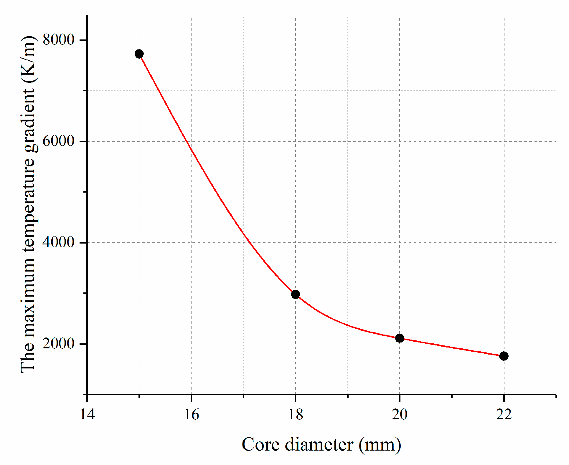
As shown in Figure 14, the maximum temperature gradient of the new current transformer could be approximately regarded as an exponential decrease with the increase of core diameter. When the diameter of guide rod was 15~18 mm, the maximum temperature gradient decreased rapidly, while the decrease tended to be moderate in the range of 18–22 mm. The maximum temperature gradient at 18 mm core diameter was 2978 K/m, which was 61.5% lower than that at 7726 k /m at 15 mm core diameter. The maximum temperature gradient at 22 mm core diameter was 1759 K/m, which was only 40.9% lower than the maximum temperature gradient at 18 mm core diameter.
It is not difficult to see that when the core diameter of the new current transformer was 18–20 mm, the change rate of hotspot temperature and maximum temperature gradient of the transformer tended to be saturated and both are in a reasonable range of values.
5. Conclusions
In this paper, a new type design of current transformer for distribution network is taken as the research object. Based on the finite element multi-physical field coupling method, the thermal field distribution law of the current transformer when it reaches the thermal steady state in the actual electromagnetic environment is calculated and analyzed, and the following conclusions are drawn:
- The temperature distribution of the main heat source guide rod of the new current transformer is in a “parabola” form. The hot temperature and the maximum temperature gradient of the transformer change linearly under different current.
- Under different external ambient temperatures, the overall maximum overheating of the transformer remains unchanged between 40 and 41 K. Although the maximum temperature gradient decreases gradually with the increase of external ambient temperature, the decline can be ignored. Due to the uneven distribution of temperature, water molecules in the internal may migrate and form condensation, which will harm the safe operation of the current transformer.
- For the guide rod, which is the main heat source of the transformer, in the case of different core diameters, its hot spot temperature and maximum temperature gradient decrease with the increase of core diameter. Among them, the maximum temperature gradient decreases exponentially with the increase of core diameter, and the rate of change tends to saturation at 18–20 mm. At this point the core diameter size is the most reasonable.
Author Contributions
Conceptualization and Formal analysis, B.D.; Writing—Original draft, Y.G.; Writing—Review & editing, C.G., Z.Z., T.W. and K.L. All authors have read and agreed to the published version of the manuscript.
Funding
This research was funded by State Grid Corporation of China, grant number W2020JSKF0677.
Data Availability Statement
Data sharing not applicable. No new data were created or analyzed in this study. Data sharing is not applicable to this article.
Conflicts of Interest
The authors declare no conflict of interest.
References
- Guo, L.; Yu, Z.; Bo, L.; Tao, D.; Yongyi, Z. Optimal design of insulation of current transformers cast by epoxy resin at high altitude. High Volt. Electr. Appl. 2010, 46, 57–60. [Google Scholar]
- Yu, G.; Dong, B.; Zhang, Z.; Xiang, N.; Bin, D.; Zhu, Z. Simulation calculation and analysis on three-dimensional electro-thermal coupling of a new type of current transformer for distribution network. In Proceedings of the 2020 IEEE International Conference on High Voltage Engineering and Application (ICHVE), Beijing, China, 6–10 September 2020; pp. 1–4. [Google Scholar]
- Shling, Z.; Zongren, P.; Peng, L.; Wei, H.; Haoran, W. The electrothermal coupling model is applied to the calculation of radial temperature and electric field distribution of high voltage dry DC bushing. Chin. J. Electr. Eng. 2013, 22, 191–200. [Google Scholar]
- Shiling, Z.; Yongsheng, H.; Naiyi, L.; Zongren, P. Finite element simulation analysis of SF6 gas insulated composite bushing structure for 1100 kV GIS. Insul. Mater. 2019, 52, 50–56. [Google Scholar]
- Pengyuan, L. Study on the Influence of Ambient Temperature Change on SF6 CT Operation Performance and Countermeasures. Ph.D. Thesis, North China Electric Power University, Beijing, China, 2016. [Google Scholar]
- Zhang, S. Evaluation of thermal transient and overload capability of high voltage bushings with ATP. IEEE Trans. Power Deliv. 2009, 24, 1295–1301. [Google Scholar] [CrossRef]
- Ramu, T.S.; Reddy, C.C. On the computation of electric field and temperature distribution in HVDC cable insulation. IEEE Trans. Dielectr. Electr. Insul. 2006, 13, 1236–1244. [Google Scholar]
- Jyothi, N.S.; Ramu, T.S.; Mandlik, M. Temperature distribution in resin impregnated paper insulation for transformer bushing. IEEE Trans. Dielectr. Electr. Insul. 2010, 17, 931–938. [Google Scholar] [CrossRef]
- Rachek, M.; Nait Larbi, S. Magnetic Eddy-Current and Thermal Coupled Models for the Finite-Element Behavior Analysis of Underground Power Cables. IEEE Trans. Magn. 2008, 44, 4739–4746. [Google Scholar] [CrossRef]
- Eslamian, M.; Vahidi, B.; Eslamian, A. Thermal analysis of cast-resin dry-type transformers. Energy Convers. Manag. 2011, 52, 2479–2488. [Google Scholar] [CrossRef]
- Azizian, D.; Bigdeli, M.; Fotuhi-Firuzabad, M. A Dynamic Thermal Based Reliability Model of Cast-Resin Dry-Type Transformers. In Proceedings of the 2010 International Conference on Power System Technology, HangZhou, China, 24–28 October 2010; pp. 1–7. [Google Scholar]
- Jang, S.-M.; Park, H.C.; Cho, S.K.; Lee, S.-H.; Cho, H.W. Thermal Analysis of Induction Heating Roll With Heat Pipes. IEEE Trans. Magn. 2003, 39, 3244–3246. [Google Scholar] [CrossRef]
- Lee, M.; Patel, D.; Abdullah, H.A.; Jofriet, J.C.; Fahrioglu, M. Air temperature effect on thermal models for ventilated dry-type transformers. Electr. Power Syst. Res. 2011, 81, 783–789. [Google Scholar] [CrossRef]
- Xiuguang, L. Finite element analysis of temperature field of SF6 CT. High Volt. Electr. Appl. 2015, 51, 121–124. [Google Scholar]
- lan, X.; Yanlong, Z.; Zikang, Y.; Daojuun, S.; Chaohui, X.; Wei, H. Analysis and calculation of temperature rise of resin cast dry transformer. High Volt. Technol. 2013, 39, 265–271. [Google Scholar]
- Arjona, M.A.; Hernandez, C.; Escarela-Perez, R.; Melgoza, E. Thermal analysis of a dry-type distribution power transformer using FEA. In Proceedings of the 2014 International Conference on Electrical Machines (ICEM), Berlin, Germany, 2–5 September 2014; pp. 2270–2274. [Google Scholar]
- Hui, J.; Hao, W.; Zhiyong, L.; Xin, W.; Peng, Z. Research on the influence of ambient temperature change on SF6 CT operation performance. Power Grid Clean Energy 2017, 33, 65–69. [Google Scholar]
- Ruan, J.; Liu, C.; Gong, R.; Liao, C. Temperature rise of a dry-type transformer with quasi-3D coupled-field method. IET Electr. Power Appl. 2016, 10, 598–603. [Google Scholar]
- Yang, Z.; Naiqiu, S.; Xiaoqing, L. Numerical calculation and analysis of temperature rise of direct-buried gas-insulated transmission lines based on finite element method. J. Wuhan Univ. 2015, 48, 820–825, 830. [Google Scholar]
- Wen, X.; Zhang, J.; Lu, H. Automatic J–A Model Parameter Tuning Algorithm for High Accuracy Inrush Current Simulation. Energies 2017, 10, 480. [Google Scholar] [CrossRef] [Green Version]
- Guojian, L.; Fenghua, W. Calculation and analysis of temperature field distribution of resin cast dry transformer. High Volt. Electr. Appl. 2016, 52, 83–89. [Google Scholar]
- Yongchun, L.; Qiaoling, W.; Caihong, Y.; Jin, Z.; Yanming, L.; Jinyuan, W. Application of three-dimensional finite element method in the calculation of temperature field and carrying capacity of locally buried cable through pipe. High Volt. Technol. 2011, 37, 2911–2917. [Google Scholar]
Figure 1.
The transformer elements.
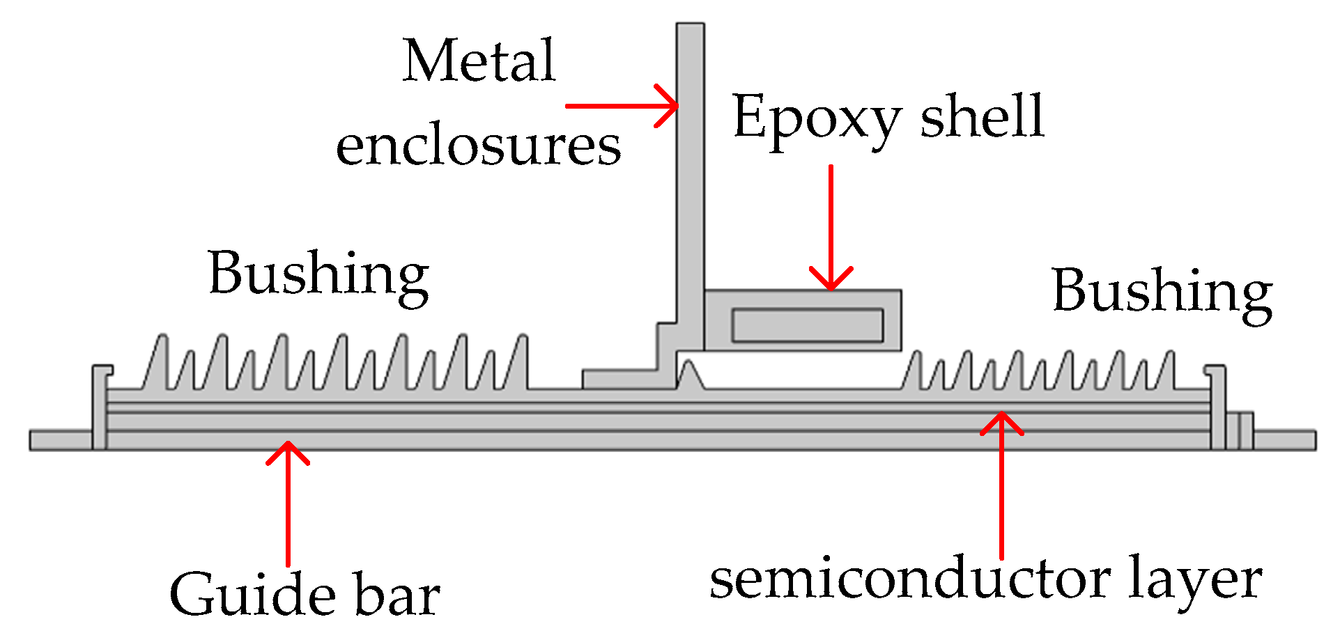
Figure 2.
Flow chart of electro-thermal coupling calculation.
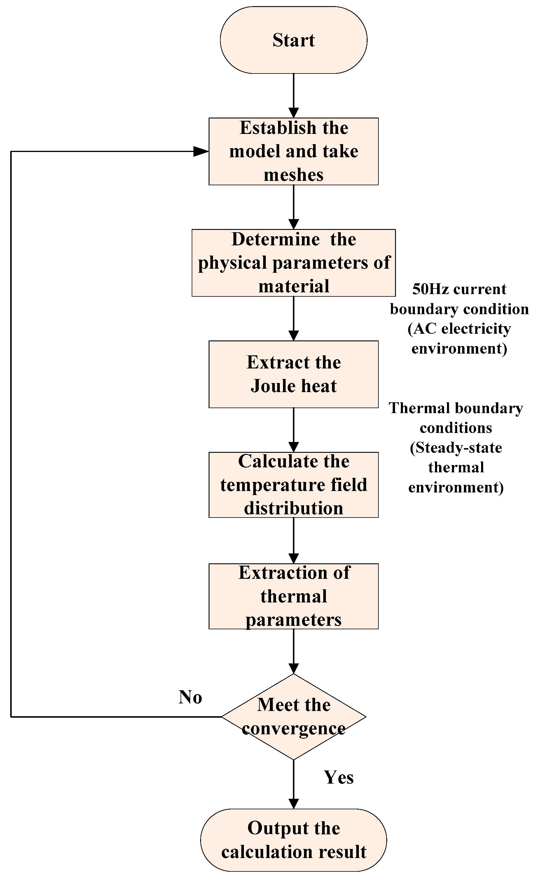
Figure 3.
The new current transformer meshes.
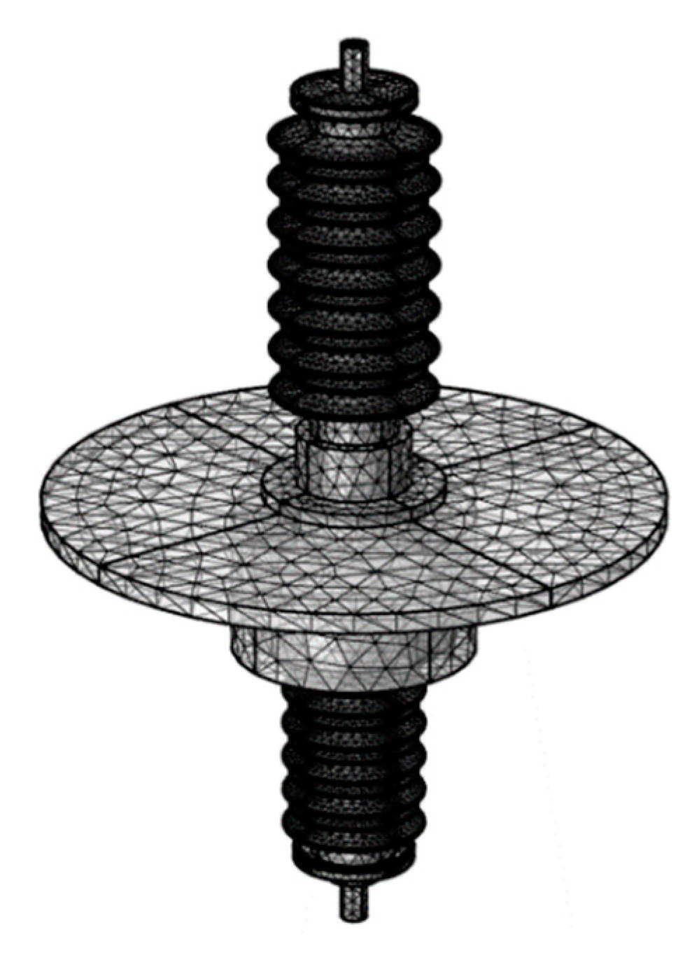
Figure 4.
Overall temperature distribution field map.
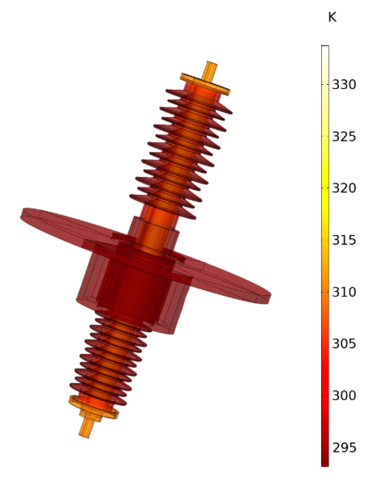
Figure 5.
Y-Z temperature distribution field map.
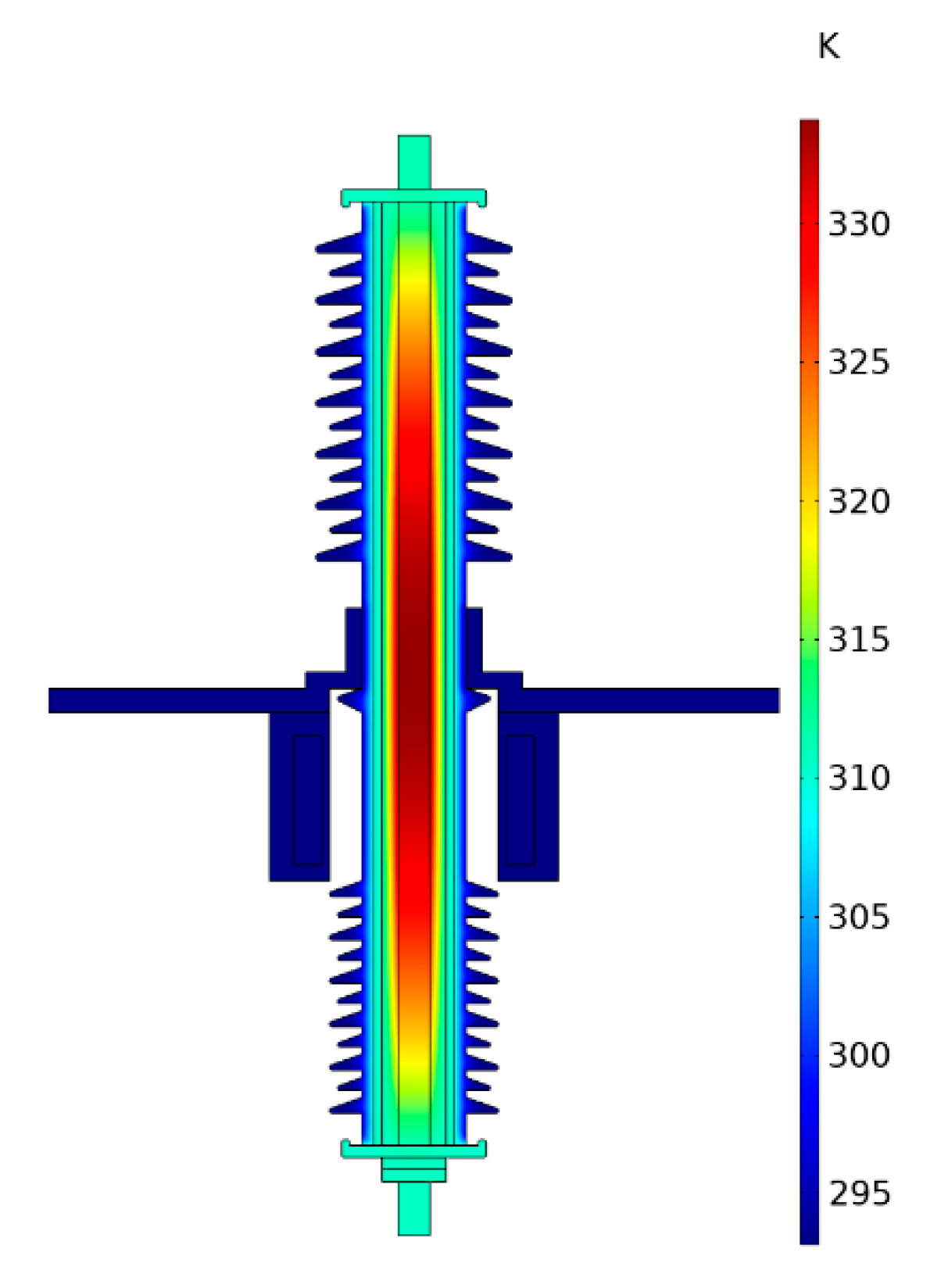
Figure 6.
Y-Z temperature gradient field map.

Figure 7.
The temperature curves of guide rod at different currents.

Figure 8.
The temperature curves of skirt under different currents.

Figure 9.
Hot spot temperatures at different currents.

Figure 10.
Maximum temperature gradients at different currents.
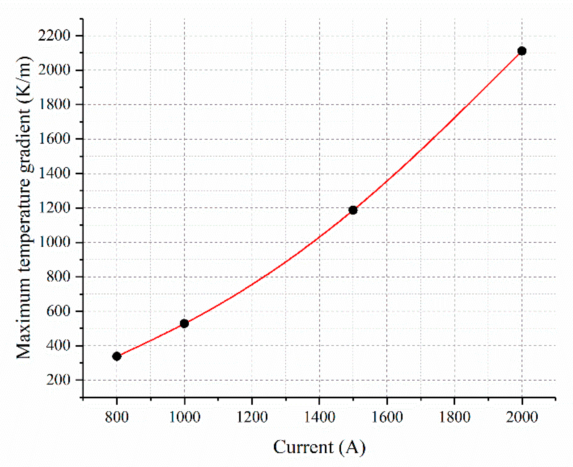
Figure 11.
Maximum overheating at different external environment temperatures.

Figure 12.
Maximum temperature gradient at different external environment temperatures.
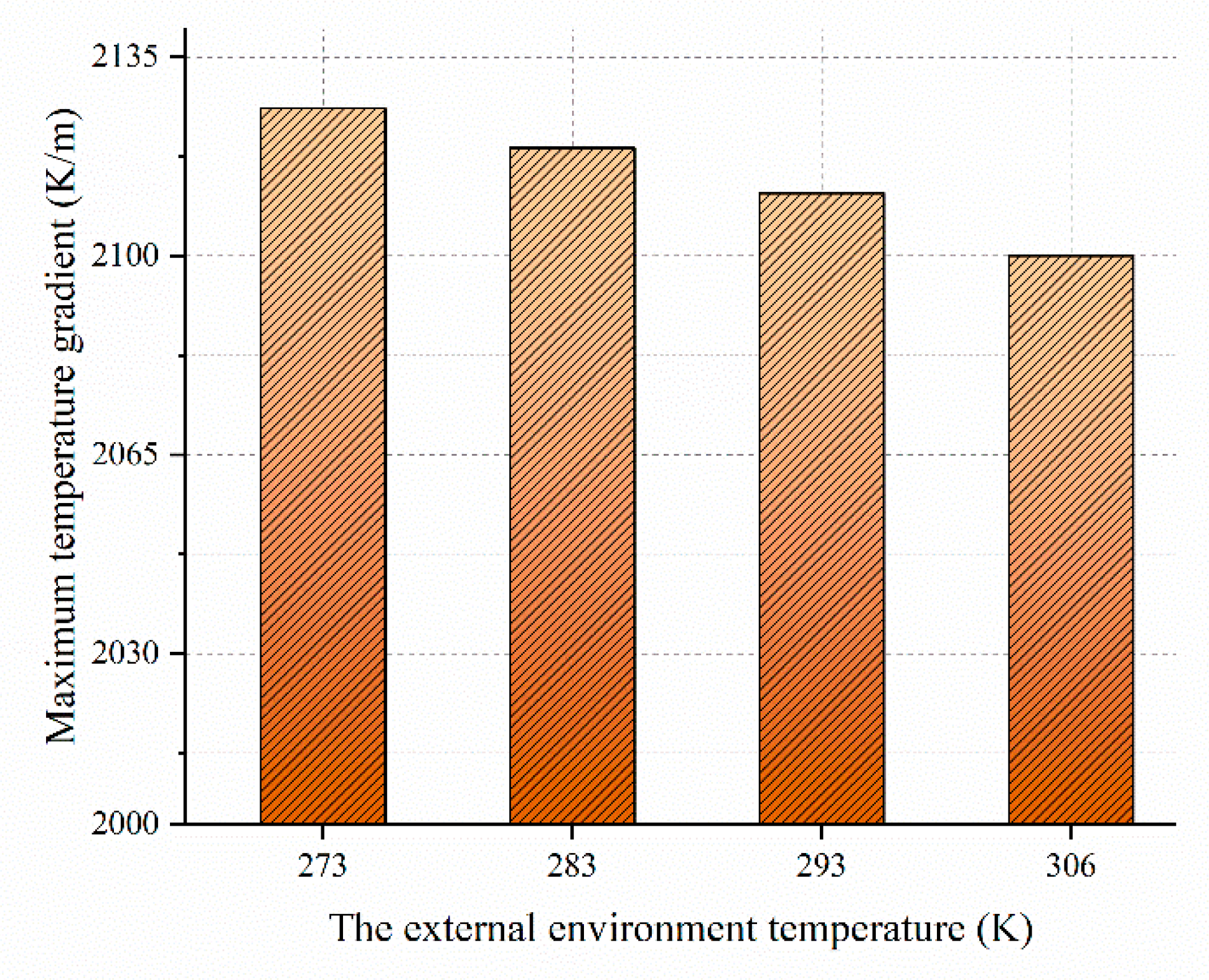
Figure 13.
Hot spot temperature at different core diameters.

Figure 14.
Maximum temperature gradient at different core diameters.

Table 1.
Structural parameter.
| Parameters | Guide Bar | The Semiconductor Layer | Epoxy Shell | Bushing | Metal Enclosures |
|---|---|---|---|---|---|
| Axial length (mm) | 1177 | 1177 | - | 410 + 290 | - |
| Radial length (mm) | 20 | 10 | 110 | - | 350 |
Table 2.
Physical property parameter.
| Parameters | Material | Conductivity (S/M) | Relative Permittivity | Heat Capacity At Constant Pressure (J/Kg·K) | Density (Kg/M3) | Thermal Conductivity (W/M·K) |
|---|---|---|---|---|---|---|
| Hardware | Copper | 5.998 × 10⁷ | - | 385 | 8700 | 400 |
| Guide rod | Aluminum | 3.774 × 10⁷ | - | 900 | 2700 | 238 |
| Bushing | Ceramic | 1.0 × 10⁻⁸ | 5.5 | 426 | 1750 | 0.06 |
| Coil shell | Epoxy-resin | 2.0 × 10⁻¹⁴ | 4.5 | 1400 | 980 | 0.276 |
Table 3.
Maximum overheating of CT under different external environment.
| The External Environment Temperature (K) | 273 | 283 | 239 | 306 |
|---|---|---|---|---|
| Hot Spot Temperature (K) | 314 | 324 | 334 | 346 |
| Temperature Difference (K) | 41 | 41 | 41 | 40 |
Table 4.
Maximum temperature gradient of CT under different external environment.
| The External Environment Temperature (K) | 273 | 283 | 239 | 306 |
|---|---|---|---|---|
| Maximum Temperature Gradient (K/M) | 2126 | 2119 | 2111 | 2100 |
Publisher’s Note: MDPI stays neutral with regard to jurisdictional claims in published maps and institutional affiliations. |
© 2021 by the authors. Licensee MDPI, Basel, Switzerland. This article is an open access article distributed under the terms and conditions of the Creative Commons Attribution (CC BY) license (http://creativecommons.org/licenses/by/4.0/).
Share and Cite
MDPI and ACS Style
Dong, B.; Gu, Y.; Gao, C.; Zhang, Z.; Wen, T.; Li, K. Three-Dimensional Electro-Thermal Analysis of a New Type Current Transformer Design for Power Distribution Networks. Energies 2021, 14, 1792. https://doi.org/10.3390/en14061792
AMA Style
Dong B, Gu Y, Gao C, Zhang Z, Wen T, Li K. Three-Dimensional Electro-Thermal Analysis of a New Type Current Transformer Design for Power Distribution Networks. Energies. 2021; 14(6):1792. https://doi.org/10.3390/en14061792
Chicago/Turabian StyleDong, Bingbing, Yu Gu, Changsheng Gao, Zhu Zhang, Tao Wen, and Kejie Li. 2021. "Three-Dimensional Electro-Thermal Analysis of a New Type Current Transformer Design for Power Distribution Networks" Energies 14, no. 6: 1792. https://doi.org/10.3390/en14061792
Note that from the first issue of 2016, this journal uses article numbers instead of page numbers. See further details here.