Article

An Experimental Study of the Heat Storage and the Discharge Performance and an Economic Performance Analysis of a Flat Plate Phase Change Material (PCM) Storage Tank

School of Urban Planning and Municipal Engineering, Xi’an Polytechnic University, Xi’an 710048, China
*
Author to whom correspondence should be addressed.
Energies 2022, 15(11), 4023; https://doi.org/10.3390/en15114023
Submission received: 26 April 2022 / Revised: 26 May 2022 / Accepted: 27 May 2022 / Published: 30 May 2022
(This article belongs to the Special Issue Phase Change Materials for Thermal Energy Storage Applications 2022)

Abstract

:
Solar heating technology has the advantages of being high efficiency, energy-saving, and environment protecting; however, the instability of solar energy and its mismatch with the variation characteristics of building heat load have caused great difficulties in the design and the efficient operation strategy of a solar system. A heat storage tank is an important part of a solar hot water system. In order to improve system efficiency, this paper proposes a flat plate PCM storage tank, establishes a mathematical model, and conducts experimental verification under different working conditions. Experiments show that in the heat storage process, the phase change material (PCM) only accounts for less than 20% of the space of the PCM storage tank, and its heat storage can reach 50% of the total heat storage of the tank. In the discharge process, the water temperature of the ordinary tank decreases by 20 °C within 1.5 h, and the phase change process lasts approximately 3 h, with the water temperature remaining at 45~50 °C during this period. In the natural cooling process, the heat discharge of the two water tanks at night was similar, while the temperature of the ordinary water tank decreased by 12 °C and that of the phase change water tank decreased by 7 °C. By simulating the dynamic simulation model of the composite solar phase change thermal storage combined with an air-cooled heat pump system, the results show that the solar heating system with a PCM storage tank (SHS-PCM) saves 34% more energy than a solar heating system with a common tank (SHS-without PCM), and the volume of the PCM storage tank is reduced to 1/5 of the ordinary tank. The investment payback period method of energy saving reconstruction is used to analyze the economy of the SHS-PCM and the SHS-without PCM, the initial investment cost of the SHS-PCM is CNY 9858 higher than the SHS-without PCM, but the annual operation cost is saved by CNY 12,100, and the project investment payback period is 0.81 years, which has energy-saving potential and economic benefits.

1. Introduction

As the global fossil energy situation is becoming increasingly tight and environmental problems are becoming more prominent, solar energy as a typical clean energy source has received more attention, and the development and the application of solar thermal technology has become a solution to energy problems [1]. However, solar energy utilization is intermittent and unstable, so auxiliary heat sources (AHS) and thermal storage tanks are usually required in solar collector systems to accommodate load fluctuations and hot water storage [2]. The thermal storage tank is an essential component in the solar heating system [3], and the traditional heat storage tank has a simple structure, small storage capacity per unit volume, large floor space, and a low effective utilization rate of water as a thermal storage medium, while the PCM is studied and applied for its characteristics of high thermal storage density and stable thermal storage [4], and the phase change thermal storage tank achieves maximum thermal storage by adding phase change thermal storage modules. Some scholars have found that the thermal conductivity of the PCM can be effectively improved by filling PCMs into porous materials such as metal foam [5,6] and using a fin structure surface [7,8] so as to enhance the thermal storage performance of the phase change water tank and system.
In an experimental study of the thermal characteristics of a PCM storage tank, Li et al. [9] proposed a multi-cell square tank with PCM, and they concluded through experimental studies that in the whole release process, the transient residual heat and the transient heating capacity of the PCM multi-cell square tank were significantly improved compared with those of the conventional water tank (CWT), its effective heat release time could be effectively extended, and the cooling rate of water temperature could be reduced, indicating that its heat release performance was obviously better than that of the CWT. Hu et al. [10] conducted experimental research on the embedded spiral coil heat exchanger with PCM. It was found that with the increase of the heat transfer fluid (HTF) flow rate, the heat storage time and the heat release time decreased in turn, which can provide constant heat output by increasing the flow rate. Xie et al. [11] experimentally investigated the thermal storage performance of the PCM storage tank, and they obtained the water flow and the spacing of heat storage plates under the best working conditions in the heat storage process. Koželj et al. [12] tested and analyzed the heat storage performance of a heat storage tank with encapsulated PCM for building heating, and they found that the heat storage capacity of a PCM heat storage tank is significantly higher than that of CWT under a certain temperature difference between the initial temperature and the final temperature; the main source of heat is PCM. Bessani et al. [13] placed the heat exchanger in a water tank, and the water and commercial paraffin circulated on both sides of the heat exchanger, respectively. The heat storage performance was experimentally studied, which increased by 65% compared to a volumetric equivalent storage tank.
In terms of the energy efficiency of systems using phase change tanks, Pop et al. [14] based on a public swimming pool project to establish a system consisting of a solar collector system and coupled with a gas-fueled boiler, showed that on the basis of the same amount of heat compared with the CWT, the volume, fuel consumption, and CO2 emissions of the PCM storage tank could be effectively reduced. Zhu et al. [15] established a solar evaporative heat pump system with a PCM storage tank, and they concluded through experimental research and system simulation analysis that the heating power consumption and daily operation cost of the system were significantly lower than those of a single heat pump heating system, the average system performance coefficient (COP) reached 3.79, and the utilization rate of solar energy was significantly improved. Ding et al. [16] proposed a typical PCM storage tank, and they established a mathematical model. The results showed that the application of PCM in a solar water heating system (SWHS) can effectively reduce the power consumption of electric auxiliary heaters (EAH), for example, the system can save up to 31% when applied to Lhasa and up to 9.9% when applied to Guangzhou, which indicates that the application of PCM in SWHS could save more electricity in areas with richer solar energy resources.
The heat, strength, temperature, and other performance of the tank during the heat storage and discharge process of the PCM storage tank with various structures are studied respectively, but in the experimental research in this field, the heat loss of the phase change water tank during the natural cooling process is less considered, which leads to inaccurate heat statistics in the actual operation. Meanwhile, for the solar heating system with a PCM storage tank, the improvement of comprehensive energy saving effect and economy is the fundamental goal, but this research is rare. For addressing these research gaps, a mathematical model is developed for the PCM storage tank using a two-dimensional transient model with a single phase change temperature in this paper, and the model is discretely solved by MATLAB software, which is useful for guiding the engineering design of this type of PCM storage tank. The focus of this paper is to experimentally investigate the effect of heat storage and discharge, the control of water temperature under the storage–discharge conditions, and the less explored natural cooling conditions of the PCM storage tank and the common tank, respectively, and to compare them with the theoretical data to verify the correctness of the mathematical model. In order to further confirm the comprehensive energy saving effect of the system, the energy saving effect is studied on the basis of the dynamic coupling model of the solar phase change heat storage heating system established by the research group, and the economic performance analysis of the energy saving reconstruction of the heat storage tank is carried out based on the actual construction project in Lhasa, which provides reference for its engineering application and promotion.

2. Mathematical Model

A mathematical model is proposed to predict the heat storage and the release performance of the flat phase change water tank, including five main steps: (1) selecting specific phase change heat storage units according to the internal heat transfer of the flat phase change water tank for research; (2) establishing an energy conservation equation of HTF and PCM based on a phase change heat storage unit; (3) introducing the dimensionless parameters to dimensionlessize the equation to obtain more essential heat transfer characteristics; (4) discretizing the equation, then solving it by MATLAB software; and (5) verifying the accuracy of the model through experimental research.
Figure 1 shows a flat plate PCM storage tank. The PCM was packed in a specially made metal box to form a phase change thermal storage unit, which is stacked in the tank. The heat exchange fluid is between each two phase change heat plates, and there are four cases of heat exchange between the HTF and the phase change plate: (1) when the cold fluid flows through, the PCM in the plate continuously discharges heat and solidifies, and most of the heat is released in the form of latent heat to the fluid; (2) when the hot fluid flows through, the PCM in the plate absorbs heat and melts continuously, storing most of the heat in the form of latent heat in the PCM; (3) when the fluid is stationary in the PCM storage tank, the hot fluid is continuously cooled to below the phase change temperature due to the external heat dissipation, and the PCM in the plate keeps discharge heat and solidifies, releasing most of the heat to the fluid in the form of latent heat; and (4) when the fluid is heated in the plate PCM storage tank, the internal heat source keeps heating the fluid to above the phase change temperature, and the thermal fluid transfers the heat to the PCM in the plate, which continues to absorb heat and melt, storing most of the heat in the form of latent heat.
In the study of heat transfer in the flat plate PCM storage tank, half of the PCM plate and half of the fluid channel are taken for research. Figure 2 shows a flat plate phase change heat storage unit model with upper and lower symmetry, and the upper and the lower boundaries can be considered as adiabatic surfaces.
Several kinds of heat transfer occurred in the mathematical model: (1) when the HTF is flows, forced convection heat transfer occurs with the plate wall, and when the HTF is stationary, this can be regarded as conducting heat to the plate wall at a constant wall temperature (natural convective heat transfer); (2) the heat conduction from the plate wall to the PCM; (3) the PCM carries on phase change heat storage; and (4) thermal conduction occurs inside the PCM.

2.1. Energy Conservation Equation

The HTF transfers heat to the PCM through the flat plate wall. At a given moment, the latent heat of the PCM is released (absorbed) and then solidified (melted), gradually forming the lower solid phase (liquid phase) region and the upper liquid phase (solid phase) region with the phase change interface as the dividing line.
PCM:
H m ρ m A m ( x , t ) t = K f m p T f ( x , t ) T m
In Equation (1), A m is the cross-sectional area of the phase-changed part of the PCM, K f m is the heat transfer coefficient, p is the wet circumference, T f is the fluid temperature, and T m is the PCM temperature.
HTF:
m f C p f T f ( x , t ) x = K f m p T f ( x , t ) T m
K f m = h f β
β ( x , t ) = R f R f + R p + R m ( x , t )
In Equation (4), R f is the convective thermal resistance of the HTF, R p is the conductive thermal resistance of package plate wall, R m is the conductive thermal resistance of the phase-changed part of the PCM.
R f = 1 / h f , R m = l m / K m , R p = l p / K p
Initial conditions: A m ( x , t = 0 ) = A m , 0 ( x ) , T f ( x , t = 0 ) = T f , 0
Boundary conditions: T f ( x = 0 , t ) = T f , i n ( t )

2.2. Dimensionless

In order to analyze the heat transfer characteristics of the phase change heat storage unit in a more general and essential way, dimensionless parameters are introduced to nondimensionalize the variables:
θ f = T f T m T f , i n T m , A ¯ m = A m A max , F O = a m t l max 2 , N T U = h f A max m f c p f , X = x L , S t e = C p m T m T i n H m , B i = h f l max K m
Among them: a m = K m ρ m C p m , l max = A max p , l m = A m p , m f = ρ f v f A f
Transforming Formulas (1) and (2) into a dimensionless equation as follows:
A m X , F o F o = S t e B i β X , F o θ f X , F o
θ f ( X , F o ) X = N T U β ( X , F o ) θ f ( X , F o )
Initial conditions: A m ( X , F o = 0 ) = A m , 0 ( X ) , θ f ( X , F o = 0 ) = θ f , 0 ( X )
Boundary conditions: T f ( X = 0 , F o ) = T f , i n ( F o )
For the flat plate phase change heat storage unit used in this paper, l m = y m , l m a x = y m a x , p = W , R m = y m / k m , y ¯ m = y m / y max . In addition, when the phase change plate encapsulated container is made of a material such as metal, the conductive thermal resistance can be negligible compared with the PCM, so there is:
β ( x , t ) = R f R f + R p + R m ( x , t ) R f R f + R m ( x , t ) = 1 1 + B i y ¯ m
Substituting the structural parameters into the mathematical model of the phase change heat transfer unit in the Equations (4) and (5):
y ¯ m X , F o F o = S t e B i 1 1 + B i y ¯ m X , F o θ f X , F o
θ f ( X , F o ) X = N T U 1 1 + B i y ¯ m ( X , F o ) θ f ( X , F o )
Initial conditions: y ¯ m ( X , F o = 0 ) = 0
Boundary conditions: θ f ( X = 0 , F o ) = 1
When the phase change interface reaches y m a x , that is, y ¯ m = 1 , the phase change interface no longer rises, therefore, after a point y ¯ m = 1 , if the phase change plate is continuously heated (cooled), the point remains y ¯ m = 1 .
The equations need to be solved by iterative calculation, so the differential equation is discretized and solved by MATLAB software. The phase change interface curve and the fluid outlet temperature after a certain period of time as well as the change of phase change interface and fluid temperature at a certain point can be obtained.

3. Experimental Research

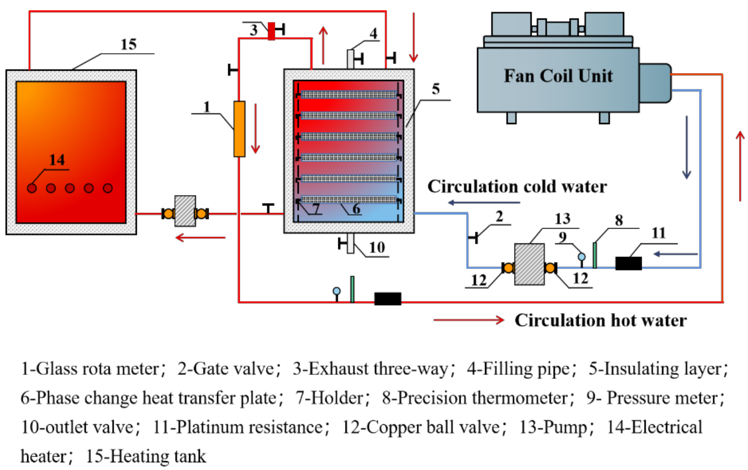
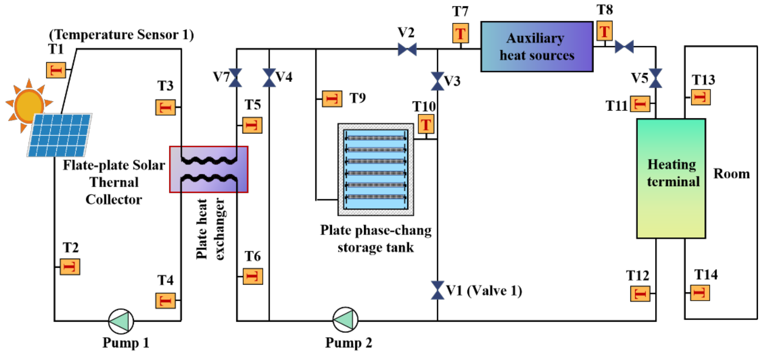
3.1. Experimental Principle

In order to compare and to test the heat storage and release of the PCM storage tank and the common tank, the heating system of the heat storage tank was built in this experiment. The organic paraffin with a phase change temperature of 50 °C, which has the advantages of good thermal stability, no subcooling, and low price was selected as the experimental PCM, and the specific thermal properties are shown in Table 1. The electric heater tank was used to replace the solar collector, and the terminal was connected to a fan coil unit (FCU) to heat the room. The experimental schematic diagram is shown in Figure 3. The water is heated to the specified temperature by an electric heater and sent to the PCM storage tank, and then the heat is sent to the room through the fan coil.
By testing the temperature change of phase change materials and heat transfer fluid under the operating conditions of heating and heating and stopping, the actual operation of the system is tested and compared with the calculated value of the theoretical model to discuss the accuracy of the theoretical model and the experimental error; the temperature change curve of an ordinary water tank system under the same operating conditions is compared to discuss the difference between a phase change thermal storage tank and an ordinary water tank in terms of heat storage and discharge capacity, etc. The differences between the phase change thermal storage tank and the common tank in terms of heat storage and discharge capacity are discussed. Three representative working conditions as shown in Table 2 are selected for the experiments.

3.2. Test Bench Construction

In order to monitor the parameters of the phase change thermal storage tank system in real time, the test bench was set up in the fan coil laboratory of Chongqing University. The automatic control measurement method of microcomputer management was adopted in the laboratory measurement and control system, and the computer measures the system parameters and controls the heating, fan coil inlet, outlet, and flow rate of the system through sensors, thus making the experiment controllable and highly operable. The main installations of the test-bed are shown in Figure 4.
The heat storage plate is a 400 mm × 400 mm × 30 mm package plate filled with paraffin wax at a phase change temperature of 50 °C. Due to the low thermal conductivity of paraffin, 10 layers × 20 × 20 grid 380 mm × 380 mm aluminum skeleton are embedded in each heat storage plate to enhance the thermal conductivity. The temperature probes are arranged inside the PCM storage tank and the common tank, and the measurement points are shown in Figure 5a,b, respectively.

3.3. Data Processing

Water heat storage/release in PCM storage tank:
Q w = C p w · M w · Δ T
In Formula (9), Q w is the heat storage (release) of the water body, kJ; C p w is the constant pressure specific heat capacity of the water body, which is 4.2 kJ/(kg·°C); M w is the mass of the water body, kg; Δ T is the temperature variation within the specified time period.
Heat storage/release of the PCM:
Q m = M m C p f · T f , 2 T m + C p s · T m T s , 1 + H m
In Formula (10), Q m is the PCM storage (release) heat, kJ; M m is the quality of PCMs, kg; C p f is the PCM liquid constant pressure specific heat capacity, kJ/(kg·°C) −1; C p s is the specific heat capacity of solid PCM at constant pressure, kJ/(kg·°C)1; T s , 1 is the solid low-temperature temperature when the PCM absorbs heat (release heat), °C; T f , 2 is the liquid low-temperature temperature when the PCM absorbs heat (release heat), °C; T m is the phase change temperature of the PCM, °C; and H m is the latent heat of the PCM, kJ/kg.

3.4. Results and Discussion

After processing the data of the three working conditions described in Table 1, the temperature curves and heat accumulation curves of each part are obtained, respectively.
(1)
Working condition 1: only open 1.5 kW heater, static heating process
Figure 6a,b shows the temperature change between the PCM storage tank and the common tank during heating, the rising trend of the water body temperature of the PCM storage tank becomes slow after about 50 °C, while the water body temperature of the common tank increases linearly, indicating that the phase change temperature of the PCM is reached, the PCM absorbs more heat and begins to undergo phase change. According to Figure 6c,d, for the PCM storage tank, from 16:30 to 18:30, the water body of the PCM storage tank absorbs 2500 kJ heat, while the water body of the common tank absorbs 5000 kJ heat, indicating that 50% of the heat in the PCM storage tank is absorbed by the PCM. It can be seen from Figure 6e that the PCM is in the phase change process from 16:30 to 18:00, and its phase change interval is 45–50 °C. The latent heat regions of each phase change plate are different due to different locations and stratification in the tank. Figure 6f is mainly based on the formula for calculating the sensible and latent heat of PCM, and it is calculated that the PCM absorbs 670 kJ/block of heat within the phase change temperature, and the heat storage of the phase change plate is 7620 kJ in total, accounting for 53.6% of the overall heat storage of the tank, while the volume of PCM is small, 0.004 m3 × 6 = 0.024 m3 in total, and the effective volume of the tank is 0.135 m3, and the phase change paraffin wax only accounts for 17.8% of the volume. It can be seen that the volume of the water tank can be effectively reduced after adding phase change wax.
Figure 6a,f gives the same parameter conditions using theoretical values compared with the measured values. The theoretical calculation in Figure 6a assumes that the phase change temperatures are 45 °C and 50 °C, respectively, and the temperature of the PCM remains unchanged during the phase change process, and the sensible heat is excluded. Therefore, before 16:00 and after 17:40, the temperature of the water in the tank changes obviously, while the water temperature basically maintains at the phase change temperature in the phase change process. In fact, the phase change interval of the PCM varies between 45 °C and 50 °C. When the water body is heated, the temperature rises evenly, but the average heating rate of the theoretical value and the experimental value are basically the same. In the curve of the theoretical value in Figure 6f, the theoretical value of the heat storage of the PCM only increases during the phase change process due to the exclusion of sensible heat, but the overall agreement between the theoretical and the experimental values is good.
(2)
Working condition 2: only open LOW gear position of FCU, system heating operation process
When the FCU is turned on to dissipate heat, the effect of turbulence in the water tank is obvious, and the heat exchange rate is faster than that of natural cooling. Compared with Figure 7a,b, it takes 5 h for the PCM storage tank to decrease from 55 °C to 32 °C, while it takes only 1 h and 50 min for the common tank. It can be seen that compared with water, the PCM can store more heat, it has a more lasting operation state in the heat discharge process, and the temperature is relatively constant and maintains the phase change temperature for a long time during heat release, which is conducive to maintaining the smooth operation of the system, and it will not cause the indoor temperature to be too high when the solar radiation is strong. Working for longer periods when solar power is in short supply can reduce the time that auxiliary heating units turn on. Working for longer periods constantly when solar power is in short supply, thus reduces the turn-on time of auxiliary heating. Compared with Figure 7c,d, for example, in one of the layers, the water body of the PCM storage tank releases about 2000 kJ heat from 14:00 to 19:20 in 5.5 h, while the water body of the common tank loses 2000 kJ heat from 15:00 to 15:50 in only 50 min, which shows the PCM can effectively maintain the ambient temperature at a constant value. Figure 7e also shows that the rate of temperature reduction of the phase change plate decreases significantly after the phase change temperature of 50 °C, which shows that the heat of phase change of the PCM is many times larger than the heat stored in the same mass of water. The theoretical values in Figure 7a,f are in good agreement with the experimental values.
(3)
Working condition 3: natural cooling process
The natural cooling condition is a simulation of the heat discharge process in the heat storage tank when the heating system stops operating at night. Comparing Figure 8a,b, the water temperature of the PCM storage tank drops from 51 °C to 44 °C (without considering under the heater) in 12 h when all the operating units of the system are stationary, with a temperature drop of 7 °C, while the temperature drop of the common tank drops by 12 °C. Figure 8c,d show that the temperature of the lower part of the tank temperature drops rapidly; the heat release of water in both the PCM storage tank and the common tank is relatively large; and the heat release of water in the lower part of the common tank is larger than that of the PCM storage tank because the outlet pipe is at the lower part of the water tank, and the measuring point is close to the outlet point, and the heat exchange with the outside is obvious. For the PCM storage tank, other parts of the water temperature and heat release are basically the same, there is no obvious stratification; for the common tank, the heat release order: lower > middle > upper indicates that the heat is mainly dissipated from the upper part. Figure 8e shows that the internal temperature of PCM mainly has three stages: uniform drop stage (22:00~3:00), slightly rise stage, and gradually drop stage. From 22:00 to 3:00 the next day, the temperature of the PCM drops by 5 °C, then it begins to discharge heat due to the phase change reaction. As can be seen in Figure 8a, the PCM releases heat to the water body after 3:00, the temperature drop of the water body becomes slower, and it also discharges continuously in the following hours so that the internal temperature has some fluctuations. By 12:00 noon, after 12 h of the discharge process, except for plate 1, the temperature of other phase change plates is below 47 °C, having basically discharged completely, the PCM storage tank heat release is more than 8000 kJ (plate 1 is not completely discharged) and the common tank heat release is 8186 kJ by calculating after 12 h of natural cooling. The above analysis shows that after 12 h of natural cooling, the water body temperature of the PCM storage tank drops from 51 °C to nearly 44 °C, while that of the common tank drops from 54 °C to 42 °C. It can be seen that the constant temperature characteristics of the water tank are obviously strengthened after adding the PCM, which is significant in practical engineering. After one night of natural heat discharge, if the temperature meets the heating requirements, the PCM storage tank can be directly heated; and, if not, it needs only a short time of heating before it can be put into use, shortening the waiting time for heating caused by the next day and also saving a lot of heat. The curve of the theoretical value in Figure 8a shows that when the phase change temperature is 50 °C, the phase change process is entered at 00:00 am, while when the phase change temperature is 45 °C, the phase change process is entered after 12:00 noon the next day. In reality, the phase change discharge stage enters after approximately 2:00 a.m., and the discharge rate is greater than the theoretical calculation value.

4. Energy Saving Comparative Analysis

In order to compare the influence of the PCM storage tank and the common tank on energy consumption of SHS, the author proposed a composite solar phase change heat storage combined with an air-cooled heat pump heating system (as shown in Figure 9), established a dynamic simulation model [17], and solved the model with the design parameters of an office building in Lhasa as input values [18].
The structure forms of the inlet water tank of the SHS-PCM and the SHS-without PCM are different, and other components and design parameters of the system are consistent. The selection of the ordinary water tank is calculated based on the “Technical Code for Solar Heating System” [19]. When the corresponding phase change thermal storage tank is selected, only the latent heat storage of PCM is considered, and the latent heat storage of the PCM storage tank is the same as the storage of common tank. The design parameters of the two kinds of water tanks are displayed in Table 3.
Figure 10a shows the statistical comparison chart of daily heat delivered by the AHS of the SHS-PCM and the SHS-without PCM, as well as the daily heat consumption of the building during the whole heating season. The average daily heating capacity of the AHS of SHS-without PCM is 3964 MJ/day, the average daily heating capacity of the AHS of SHS-PCM is 2202 MJ/day, and the average daily heat consumption of the building is 5225 MJ/day. It can be seen from the figure that part of the daily heating capacity of the SHS-without PCM is higher than that of the building, which is due to the serious heat dissipation of the common tank, at this time, the AHS should not only provide indoor heating but also supplement the heat dissipation loss of the common tank.
Figure 10b shows the proportion of heat delivered by AHS, heat storage tank, and solar collector in the SHS-without PCM and the SHS-PCM during the whole heating season. It can be seen from the diagram that the AHS, the common tank, and the solar collector in the SHS-without PCM provide 76%, 14%, and 10% heat, respectively, and the energy efficiency rate is 24%. The auxiliary heat source, phase change water tank, and solar collector in the SHS-PCM provide 42%, 5%, and 53% heat, respectively, and the energy efficiency rate is 58%.
Based on Figure 10, the energy-saving effect of the SHS-PCM is more obvious, which saves 34% of the energy compared with the SHS-without PCM. Additionally, the PCM storage tank volume reduced to 1/5 of the common tank. However, it is worth mentioning that in the SHS-PCM, solar energy is more directly supplied to the indoor end by the solar collector, and the contribution rate of the PCM storage tank to the end heating is low, which is caused by the low thermal conductivity of the selected PCM. Therefore, further optimization of the PCM storage tank is the key point of future work.

5. Economic Analysis

Economic performance of energy saving retrofit of water tank in solar heating system.

5.1. Water Tank Initial Investment Analysis

The tank of the SHS-PCM is different from that of the SHS-without PCM only in the structure of the water tank, and other parts of the system and design parameters are consistent. Therefore, only the initial investment cost of the ordinary water tank and the PCM storage tank shall be analyzed on the basis of the same storage heat. The initial investment of this project is mainly the equipment cost, and the installation, construction, and debugging cost are not be taken into account. Refer to Table 3 for specific dimensions and specifications. The price of a water tank shall be CNY 10,600 for a 6-ton capacity water tank and CNY 31,000 for a 30-ton capacity water tank according to the market price and in consideration of the surface area and other factors. The estimated price of other relevant materials is calculated according to the following indicators [20,21]:
Stainless steel unit quality cost: CNY 17.1/kg.
Paraffin wax unit quality cost: CNY 7.6/kg.
Table 4 shows that the initial investment of the SHS-PCM is increased by CNY 9858, which is approximately 31.8% when compared with the SHS-without PCM on the basis of the same amount of heat storage. However, after the PCM storage tank is used, the tank volume is reduced to 1/5 of the common tank, which is convenient for installation and maintenance.

5.2. Energy Saving Analysis in Operation of SHS

Based on an office building in Lhasa, heating in winter lasts 136 days from 4 November to 19 March the following year. The heating operation time is set to 9:00–19:00 every day. The heat is supplied by a combination system of a solar collector, a heat storage water tank and an air source heat pump.
The rated heat production capacity of the air source heat pump selected in this project is 70 KW, the rated power is 29.1 kW, and the COP under the rated working condition is 2.4. The total heat load in the heating season is 98.672 MW through DeST software simulation calculation, and the total power consumption of the air source heat pump is 71.05 MW·h according to its energy consumption system simulation calculation. The civil electricity price in Lhasa is CNY 0.4993/kW·h [22], and the operation cost of the SHS-without PCM in heating season is CNY 35,500/year. It can be concluded from Figure 10 that the energy saving effect of the SHS-PCM is more remarkable than the SHS-without PCM, which saves 34% more energy. Therefore, the total power consumption of SHS-PCM is 46.893 MW·h, and the total operating cost is CNY 23,400/year. In summary, the SHS-PCM saves CNY 12,100/year compared to the SHS-without PCM.

5.3. Analysis of Payback Period of Energy Saving Reconstruction Investment

The reconstruction investment payback analysis of this project is based on the energy saving of the system, such as water, coal and gas saving, and cycle electricity saving. It is a common measure to convert energy saving into a corresponding amount and compare it with investment. The payback period “N” for system investment is the increased initial investment in the construction of the SHS-PCM divided by the operating costs saved during the heating season, as shown in Formula (11):
N = I P I C M C M P
In Formula (11), I P is the initial investment costs of the SHS-PCM, CNY; I C is the initial investment costs of the SHS-without PCM, CNY; M P is the operating cost of the SHS-PCM, CNY; M C is the operating cost of the SHS-without PCM, CNY.
Compared with the SHS-without PCM, the initial investment of the SHS-PCM increases by CNY 9858, but the annual operating cost is saved by CNY 12,100. According to the formula calculation, it can be concluded that the payback period of the energy saving reconstruction investment of a water tank in SHS is 0.81 years.

6. Conclusions

In this paper, the mathematical model of the flat plate PCM storage tank is established, and the experimental results under different working conditions show that the theoretical values are in good agreement with the experimental values. The energy saving effect of SHS-PCM is discussed by dynamic coupling simulation, and its application value is discussed by economic performance analysis of energy saving reconstruction. The specific conclusions are as follows:
(1)
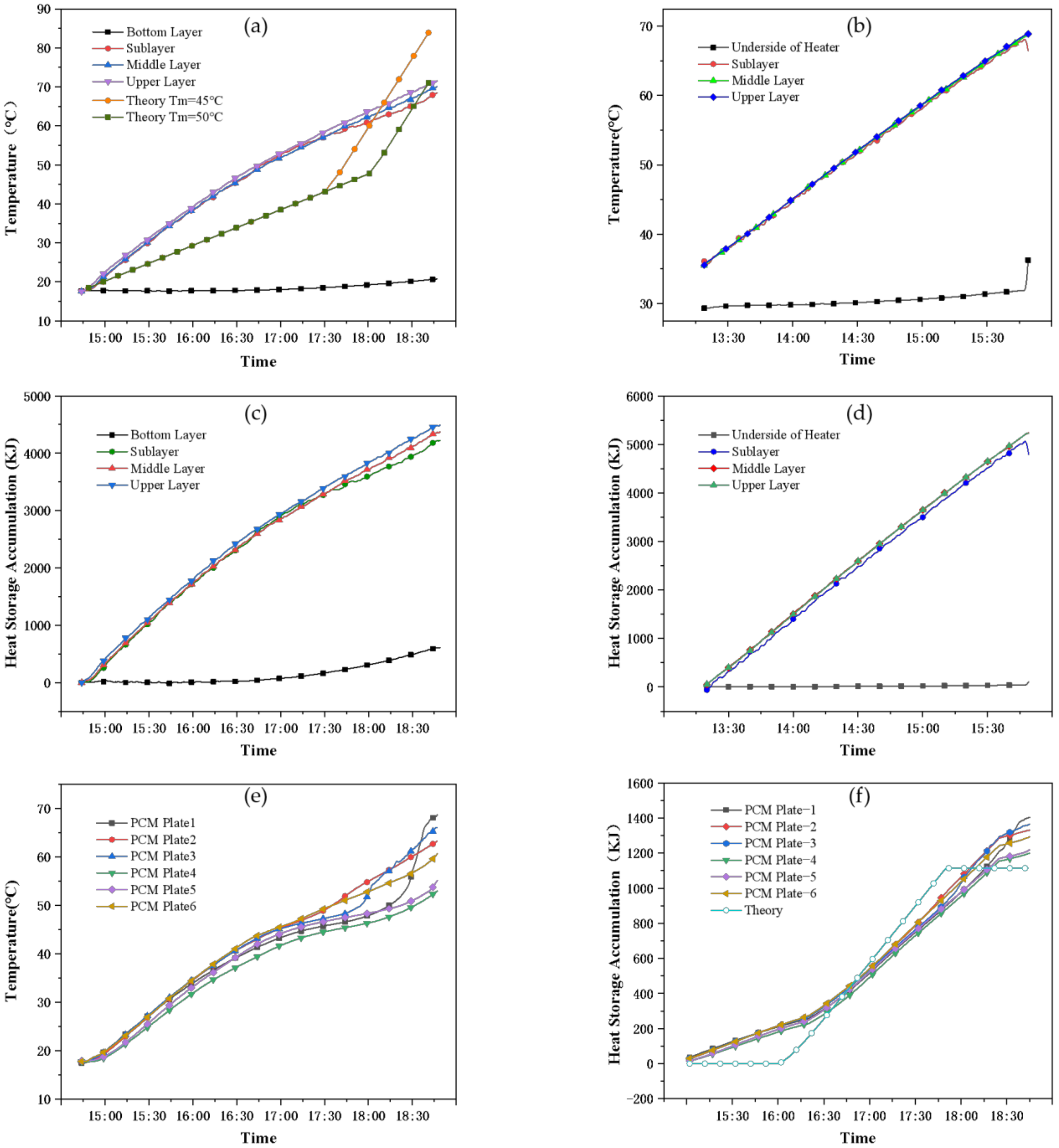
Experimental condition 1: in the heat storage process, the PCM only occupy less than 20% of the space of the PCM storage tank, but the heat storage can reach 50% of the total heat storage. Under the premise of absorbing equal heat, within two hours, the temperature of the common tank is increased by 35 °C, the temperature of the PCM storage tank is only increased by 25 °C, and the period of the phase change is approximately 1.5 h.
(2)
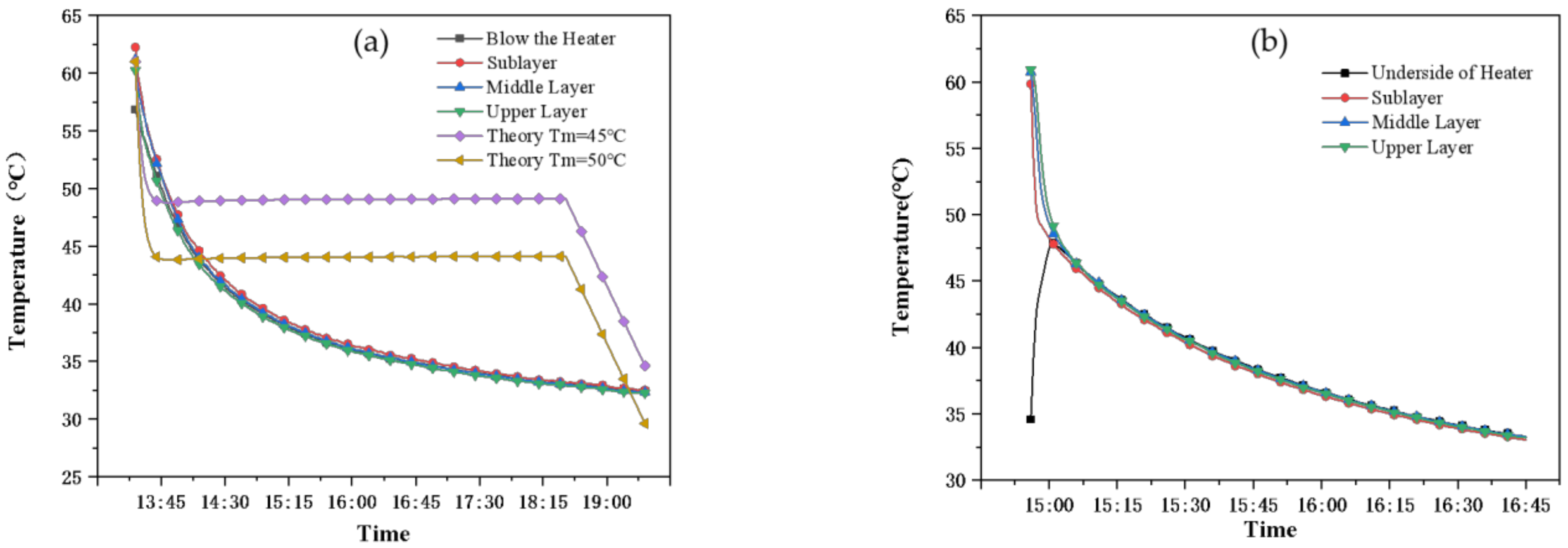
Experimental condition 2: in the heat discharge process, the water temperature of the common tank decreased by 20 °C for 1.5 h, while the PCM storage tank required 5 h for the same temperature drop, and the internal disturbance was strengthened to strengthen the thermal conductivity. The phase change process lasted for approximately 3 h throughout the heat discharge process so that the water temperature was basically maintained at 45–50 °C during this period. The heat release of the PCM was 4800 kJ, accounting for 42.5% of the total heat release of the water tank.
(3)
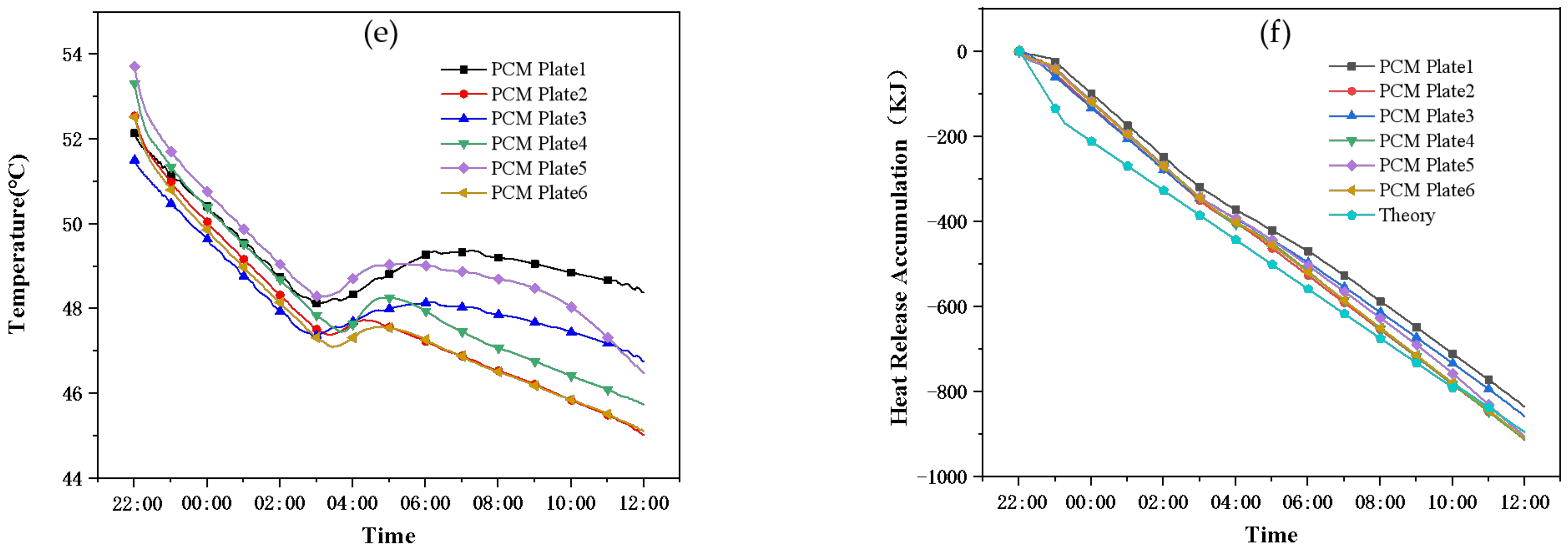
Experimental condition 3: in the natural cooling process, after 12 h of heat discharge at night, the total heat discharge of the PCM storage tank is 8000 kJ, among which the heat discharge of the PCM is 4800 kJ (accounting for 60%), the heat discharge of the common tank is 8186 kJ. The heat discharge of the two water tanks is similar, while the temperature of the common tank dropped by 12 °C and that of the PCM storage tank only dropped by 7 °C, which can effectively reduce the temperature drop and it is conducive to reducing the auxiliary energy opening time of the next day and saving energy.
(4)
Through system simulation, it is found that the SHS-PCM saves 34% more energy than the SHS-without PCM, and the volume of the water tank is reduced to 1/5 of common water tank.
(5)
Through economic analysis, it is found that compared with the SHS-without PCM, the initial investment cost of the SHS-PCM increases by CNY 9858, the annual operation cost saves CNY 12,100, and the payback period for energy saving renovation projects is 0.81 years, which possesses certain energy saving potential and economic benefits.
The single temperature method model established in this study requires a lot of time in data processing. In addition, the experimental study and an energy-saving economic analysis are carried out on the PCM storage tank itself. In a subsequent study, the mathematical model of temperature, flow, and other parameters changing with time will be explored so as to simplify the calculation time, and a series of studies on the dynamic coupling of the PCM storage tank integrated in the system will be considered.

Author Contributions

Conceptualization, J.Z.; methodology, J.Z. and J.G.; software, J.L. and Y.B.; validation, T.Q. and J.Z.; formal analysis, J.G., B.Z. and Y.B.; resources, J.Z.; data curation, J.L.; writing—original draft preparation, J.Z., J.G. and B.Z.; writing—review and editing, J.G.; visualization, J.G.; supervision, T.Q.; project administration, J.Z.; funding acquisition, Xi’an Polytechnic University. All authors have read and agreed to the published version of the manuscript.

Funding

This research was funded by Xi’an Polytechnic University, grant number 107020491.

Informed Consent Statement

Not applicable.

Conflicts of Interest

The authors declare no conflict of interest.

Nomenclature

A area (m2)
a weld size (m)
B i Biot number
C p constant pressure specific heat (J·kg−1·K−1)
F o Fourier number
H height (m)
h convection heat transfer coefficient (W·m−2·K−1)
K heat transfer coefficient (W·m−2·K−1)
L phase change plate length (m)
l length (m)
m mass flow (kg·s−1)
N T U heat transfer unit number
p wet perimeter (m)
R thermal resistance (m2·K·W−1)
S t e Stanton number
t t calculation step (s)
W phase change plate width (m)
X dimensionless length
x phase change distance (m)
y dimensionless thickness
Greek symbols
ρ Density (kg·m−3)
λ thermal conductivity (W·m−1·K−1)
θ dimensionless temperature
β dimensionless thermal resistance
υ specific volume (m3·kg−1)
Subscripts
f fluid
i n input
m phase change material
m a x maximum
p package plate wall
Abbreviation
AHSauxiliary heat source
COPcoefficient of performance
CWTconventional water tank
EAHelectric auxiliary heater
FCUfan coil unit
HTFheat transfer fluid
PCMphase change material
SHSsolar heating system
SHS-PCMsolar heating system with PCM storage tank
SHS-without PCMsolar heating system with common tank
SWHSsolar water heating system

References

  1. Chen, H.; Ji, J.; Pei, G.; Yang, J.; Zhang, Y. Experimental and numerical comparative investigation on a concentrating photovoltaic system. J. Clean. Prod. 2018, 174, 1288–1298. [Google Scholar] [CrossRef]
  2. Chen, H.; Wang, Y.; Li, J.; Cai, B.; Zhang, F.; Lu, T.; Yang, J.; Jiang, L.; Zhang, Y.; Zhou, J. Experimental research on a solar air-source heat pump system with phase change energy storage. Energy Build. 2020, 228, 110451. [Google Scholar] [CrossRef]
  3. Teamah, H.; Lightstone, M.; Cotton, J. An alternative approach for assessing the benefit of phase change materials in solar domestic hot water systems. Sol. Energy 2017, 158, 875–888. [Google Scholar] [CrossRef]
  4. Wang, Z.; Zhang, H.; Dou, B.; Zhang, G.; Wu, W. Influence of inlet structure on thermal stratification in a heat storage tank with PCMs: CFD and experimental study. Appl. Therm. Eng. 2019, 162, 114151. [Google Scholar] [CrossRef]
  5. Ghahremannezhad, A.; Xu, H.; Salimpour, M.R.; Wang, P.; Vafai, K. Thermal performance analysis of phase change materials (PCMs) embedded in gradient porous metal foams. Appl. Therm. Eng. 2020, 179, 115731. [Google Scholar] [CrossRef]
  6. Iasiello, M.; Mameli, M.; Filippeschi, S.; Bianco, N. Simulations of paraffine melting inside metal foams at different gravity levels with preliminary experimental validation. In Proceedings of the 37th UIT Heat Transfer Conference, Journal of Physics: Conference Series, Padova, Italy, 24–26 June 2020; Volume 1599. [Google Scholar] [CrossRef]
  7. Bianco, N.; Busiello, S.; Iasiello, M.; Mauro, G.M. Finned heat sinks with phase change materials and metal foams: Pareto optimization to address cost and operation time. Appl. Therm. Eng. 2021, 197, 117436. [Google Scholar] [CrossRef]
  8. Tang, J.; Xie, Y.; Chang, S.; Yan, Z.; Wu, H.; Zhang, H. Performance analysis of acceleration effect on paraffin melting in finned copper foam. Appl. Therm. Eng. 2021, 202, 117826. [Google Scholar] [CrossRef]
  9. Li, J.; Zhang, Y.; Ding, P.; Long, E. Experimental and simulated optimization study on dynamic heat discharge performance of multi-units water tank with PCM. Indoor Built Environ. 2020, 30, 1531–1545. [Google Scholar] [CrossRef]
  10. Hu, M.-H.; Xu, T.; Chiu, J.N. Experimental analysis of submerged coil and encapsulated slab latent heat storage. Appl. Therm. Eng. 2022, 209, 118259. [Google Scholar] [CrossRef]
  11. Xie, L.; Lv, Y.; Lu, J.; Li, Y.; Liu, S.; Zou, Q.; Wang, X. Heating storage performance of a water tank–combined phase change material:An experimental case study. Adv. Mech. Eng. 2017, 9, 1687814017724071. [Google Scholar] [CrossRef] [Green Version]
  12. Koželj, R.; Mlakar, U.; Zavrl, E.; Stritih, U.; Stropnik, R. An experimental and numerical analysis of an improved thermal storage tank with encapsulated PCM for use in retrofitted buildings for heating. Energy Build. 2021, 248, 111196. [Google Scholar] [CrossRef]
  13. Besagni, G.; Croci, L. Experimental study of a pilot-scale fin-and-tube phase change material storage. Appl. Therm. Eng. 2019, 160, 114089. [Google Scholar] [CrossRef]
  14. Pop, O.G.; Balan, M.C. A numerical analysis on the performance of DHW storage tanks with immersed PCM cylinders. Appl. Therm. Eng. 2021, 197, 117386. [Google Scholar] [CrossRef]
  15. Zhu, C.; Li, B.; Yan, S.; Luo, Q.; Li, C. Experimental research on solar phase change heat storage evaporative heat pump system. Energy Convers. Manag. 2021, 229, 113683. [Google Scholar] [CrossRef]
  16. Ding, Z.; Wu, W.; Chen, Y.; Li, Y. Dynamic simulation and parametric study of solar water heating system with phase change materials in different climate zones. Sol. Energy 2020, 205, 399–408. [Google Scholar] [CrossRef]
  17. Zhao, J.; Ji, Y.; Yuan, Y.; Zhang, Z.; Lu, J. Seven Operation Modes and Simulation Models of Solar Heating System with PCM Storage Tank. Energies 2017, 10, 2128. [Google Scholar] [CrossRef] [Green Version]
  18. Zhao, J.; Ji, Y.; Yuan, Y.; Zhang, Z.; Lu, J. Energy-Saving Analysis of Solar Heating System with PCM Storage Tank. Energies 2018, 11, 237. [Google Scholar] [CrossRef] [Green Version]
  19. GB 50495-2019; Technical Standard for Solar Heating System. Ministry of Housing and Urban-Rural Development of the People’s Republic of China, China Architecture & Building Press: Beijing, China, 2019.
  20. Network, G.I. Latest Price Inquiry of Paraffin. Available online: https://www.cngold.org/shila/c7889490.html (accessed on 10 December 2021).
  21. Shaanxi Iron and Steel Co. Ltd. (China). Steel Benchmark Price Index. Available online: https://www.shaangang.com/info/2015061510/201507291415245127/202112210327219393.shtml (accessed on 21 December 2021).
  22. People’s Government of Tibet Autonomous Region. Notification of the People’s Government of Tibet Autonomous Region on Adjusting the Sale Electricity Price of the Region. Available online: http://www.xizang.gov.cn/zwgk/xxgk_424/zxxxgk/201902/t20190223_63441.html (accessed on 1 July 2014).
Figure 1. (a) Front view of the PCM storage tank; (b) 1-1 cross sectional of the PCM storage tank.
Energies 15 04023 g001
Figure 2. Mathematical model of phase change heat storage unit.
Energies 15 04023 g002
Figure 3. Schematic diagram of PCM storage tank heating system.
Energies 15 04023 g003
Figure 4. Main installations of the test-bed: (a) PCM storage tank; (b) Fan coil unit; (c) Phase change heat storage plates.
Energies 15 04023 g004
Figure 5. (a)Test points of temperature in the PCM storage tank; (b)Test points of temperature in the common tank.
Energies 15 04023 g005
Figure 6. In working condition 1: (a) Water temperature curve of the PCM storage tank; (b) Water temperature curve of the common tank; (c) Heat storage accumulation curve of the PCM storage tank; (d) Heat storage accumulation curve of the common tank; (e) Temperature curve of the PCM plate; (f) Heat storage accumulation curve of the PCM plate.
Energies 15 04023 g006
Figure 7. In working condition 2: (a) Water temperature curve of the PCM storage tank; (b) Water temperature curve of the common tank; (c) Heat release accumulation curve of the PCM storage tank; (d) Heat release accumulation curve of the common tank; (e) Temperature curve of the PCM plate; (f) Heat release accumulation curve of the PCM plate.
Energies 15 04023 g007aEnergies 15 04023 g007b
Figure 8. In working condition 3: (a) Water temperature curve of the PCM storage tank; (b) Water temperature curve of the common tank; (c) Heat release accumulation curve of the PCM storage tank; (d) Heat release accumulation curve of the common tank; (e) Temperature curve of the PCM plate; (f) Heat release accumulation curve of the PCM plate.
Energies 15 04023 g008aEnergies 15 04023 g008b
Figure 9. Schematic diagram of composite solar phase change heat storage combined with air-cooled heat pump heating system.
Energies 15 04023 g009
Figure 10. (a) Daily heat delivered by the AHS of the SHS-PCM and the SHS-without PCM, as well as daily heat consumption of the building; (b) the proportion of heat delivered by AHS, heat storage tank, and solar collector in the SHS-without PCM and the SHS-PCM.
Energies 15 04023 g010
Table 1. Thermal properties of paraffin for test.
PCMLatent HeatLiquid Specific Heat CapacitySolid Specific Heat CapacityDensityThermal Conductivity
kJkJ/(kg·°C)kJ/(kg·°C)kg/m3W/(m·K)
Paraffin2002.93.20.87 × 1030.4
Table 2. Working condition selection.
Working ConditionProcess DescriptionHeater Power FCU Gear PositionPump Switching State
1Heat storage process1.5 kWStopOff
2Heat discharge process0 kWLowOn
3Natural cooling process0 kWStopOff
Table 3. Design parameters for common tank and PCM storage tank.
UnitCommon TankPCM Storage Tank
Heat storage capacityGJ0.630.63
Volume of tankm33 × 2.5 × 43 × 2.5 × 0.8
Volume of PCM platem33 × 2.5 × 0.08
Number of PCM plate 6
PCM paraffin wax
Phase change temperature°C47
Terminal form FCUFCU
Supply and return heating temperature°C45/4045/40
Table 4. Initial investment comparison of tank.
PCM Storage Tank
MaterialQuantityUnit Price/CNYTotal Price/CNY
Insulation Water Tank110,60010,600
Package Plate610766456
Paraffin Plate63,96723,802
Total 40,858
Common Tank
Insulation Water Tank131,00031,000
Total 31,000
Publisher’s Note: MDPI stays neutral with regard to jurisdictional claims in published maps and institutional affiliations.

