Article

Capacitor Voltage Balancing of a Grid-Tied, Cascaded Multilevel Converter with Binary Asymmetric Voltage Levels Using an Optimal One-Step-Ahead Switching-State Combination Approach †

1
Department of Electrical Engineering, Bundeswehr University Munich, Werner-Heisenberg-Weg 39, 85579 Neubiberg, Germany
2
Department of Electrical Engineering, Chalmers University of Technology, Hörsalsvägen 11, 41258 Gothenburg, Sweden
*
Author to whom correspondence should be addressed.
This article is a post conference article of the paper, “Sensorless Capacitor Voltage Balancing of a Grid-Tied, Single-Phase Hybrid Multilevel Converter with Asymmetric Capacitor Voltages Using Dynamic Programming”, Published at the IECON 2020, Singapore.
Energies 2022, 15(2), 575; https://doi.org/10.3390/en15020575
Submission received: 16 November 2021 / Revised: 21 December 2021 / Accepted: 5 January 2022 / Published: 13 January 2022
(This article belongs to the Special Issue Building Automation and Special Electrical Systems)

Abstract

:
This paper presents a novel capacitor voltage balancing control approach for cascaded multilevel inverters with an arbitrary number of series-connected H-Bridge modules (floating capacitor modules) with asymmetric voltages, tiered by a factor of two (binary asymmetric). Using a nearest-level reference waveform, the balancing approach uses a one-step-ahead approach to find the optimal switching-state combination among all redundant switching-state combinations to balance the capacitor voltages as quickly as possible. Moreover, using a Lyapunov function candidate and considering LaSalle’s invariance principle, it is shown that an offline calculated trajectory of optimal switching-state combinations for each discrete output voltage level can be used to operate (asymptotically stable) the inverter without measuring any of the capacitor voltages, achieving a novel sensorless control as well. To verify the stability of the one-step-ahead balancing approach and its sensorless variant, a demonstrator inverter with 33 levels is operated in grid-tied mode. For the chosen 33-level converter, the NPC main-stage and the individual H-bridge modules are operated with an individual switching frequency of about 1 kHz and 2 kHz, respectively. The sensorless approach slightly reduced the dynamic system response and, furthermore, the current THD for the chosen operating point was increased from 3.28 to 4.58 in comparison with that of using the capacitor voltage feedback.

1. Introduction

Multilevel converters (MLC) are commonly used for high voltage applications in power systems [1,2] or, sometimes, these are even suggested for large electric drives [3,4]. Lately, multilevel inverters are gaining in interest for low voltage applications ( V < 1 k V ) due to their advantages in comparison to two-level converters, such as fault-tolerant operation capability [5,6], reduced common mode noise emissions [7,8] and the application of cheap, energy efficient low-voltage MOSFETs [9,10,11].
In [12,13,14], the topology of a cascaded H-bridge or a hybrid MLC (NPC mainstage) is shown. The additional series-connected H-bridges should help to lower the amount of output voltage harmonics and, thus, to reduce the size of the passive components, such as the grid or EMI-filter, or to improve the output current quality. To properly operate an MLC with capacitor modules, the capacitor voltages must be balanced. Therefore, several balancing algorithms can be found for symmetric MLCs [15,16,17,18,19]. As for example described in [15], self-balancing is typically achieved when using phase-shifted PWM, which introduces additional differential mode harmonics, lowering the current THD. Using asymmetric DC link voltage levels for the series-connected H-bridges can increase the output waveform’s quality, whereas the possibility to balance the capacitor voltages is compromised [14,20,21]. As stated in [14,21], the charge balance control for an asymmetric inverter with a voltage ratio of three cannot be achieved. To overcome this problem, only isolated voltage sources, charged from the mains, such as described in [22], or supplied by additional DC converters, as shown in [23], could be used. This approach requires a rectifier stage or a DC converter for each H-bridge module, introducing additional system costs. The authors of [24] suggest to replace only a limited selection of capacitor modules by additional isolated voltage sources, acting as charge buffers. Similarly, in [14,25,26] it is suggested to combine a number of redundant high and low resolution cells, which help to maintain the capacitor charge balance, whereas the number of output levels is reduced.
In contrast, to maintain a high number of output levels and to properly balance the individual capacitor voltages, an asymmetric voltage grading by a factor of two (binary asymmetric) is suggested as a compromise in [12,27,28,29,30]. As described in [12,28], a predetermined switching scheme relative to the modulation index and the displacement power factor can be used to maintain the capacitor charge balance when using a voltage grading ratio of two. However, in [28] only one capacitor module is considered and a predetermined switching scheme, as in [12], requires a large memory for the lookup table. In [31,32,33] it is shown that a predetermined switching pattern can be even used to operate the inverter without measuring the capacitor voltages. Nonetheless, in [31,32,33] only a symmetric MLC is considered. In contrast, the authors of [29] suggest a self-balancing modulation scheme for binary asymmetric MLCs without measuring (sensorless) the floating capacitors’ voltages. The suggested modulation scheme in [29] alternatively utilizes redundant switching-sate combinations, referred to as cell-voltage combinations. When using the approach in [29] with nearest-level control, the capacitors’ charges are balanced over several electrical fundamental periods and, thus, according to [30], big capacitors are required. Therefore, in [29] the binary asymmetric inverter is operated with PWM and, thus, the provided solution actually resembles a generic self-balancing approach, typically achieved phase-shifted PWM [15].

Research Contribution and Scope

As an extended post-conference article of [34], the research contribution of this paper is two-fold. First, a novel balancing algorithm for the capacitor voltages of a binary asymmetric cascaded multilevel inverter is derived. The suggested algorithm uses an optimal, one-step-ahead switching-state combination approach to balance the capacitor voltages as quickly as possible. In comparison to that of the methods available in [14,15,16,17,18,24,28,29,30], the presented algorithm utilizes a low switching frequency (couple of k Hz ) and it achieves a quick dynamic response without requiring any additional hardware. Moreover, it can be easily applied to higher level asymmetric MLCs operated with nearest-level control (NLC). Second, with the help of a Lyapunov function, based on the energy stored in the grid filter and the capacitor modules, and considering LaSalle’s invariance principle, it is shown that an offline calculated trajectory of optimal switching-state combinations for each discrete output voltage level can be used to operate (asymptotically stable) the inverter without measuring any of the capacitor voltages, achieving a novel self-balancing approach as well. In comparison to that of the sensorless approach in [29], the capacitance requirement according to [30] for NLC is reduced and only a small lookup table is required.
To experimentally verify the effectiveness of the optimal, one-step-head switching-state combination approach and its sensorless variant, a demonstrator inverter from Imperix Ltd. and a simple, inductive grid filter is used. The setup is operated in grid-tied operation feeding active power to the grid. Within the scope of this paper, the converter and the grid filter design is not considered, since the major focus lies on the voltage balancing algorithm.

2. Asymmetric Cascaded Multilevel Converter Basics

The topology of a grid-connected, asymmetric, hybrid multilevel converter based on an NPC main stage and n cascaded H-bridges, can be seen in Figure 1. Due to the voltage grading of adjacent converter modules, this topology is referred to as exponential modular multilevel converter (EMMC) in [27]. Using an NPC mainstage configuration, the depicted single-phase EMMC can be easily extended to a three-phase converter. The 800 V NPC mainstage could be replaced by a 400 V H-bridge stage. Then, the converter would resemble a generic cascaded H-bridge converter with asymmetric capacitor voltages. Therefore, the presented theory can be easily applied to different variants of cascaded or hybrid multilevel inverters.
For simplicity, a lossy L-filter with an inductance L filter and a series resistance R filter is chosen as a grid-filter within the scope of this paper’s analysis. Alternatively to a pure inductive filter, an LCL-filter could be chosen, as for example described in [35,36]. The DC link voltage V DC must be larger than the peak value of the grid voltage ( V AC , pk = 2 × 230 V ) to control both the active and the reactive power flow. For example, for a sufficient control margin, it might be suitable to chose a DC link voltage of V DC = 350 V . To charge up the capacitors to the their desired reference voltages, a charging resistor R charging is initially used. During normal operation, the charging resistor R charging is bypassed.

2.1. Switching-States

The semiconductor switches of the main stage (NPC module) are operated in pairs and only adjacent switches should be activated at the same time. If three switches in series are activated, as for example S 1 , NPC , S 2 , NPC and S 3 , NPC , one DC source is short-circuited. Therefore, the switching-state of the NPC main stage relative to the individual switches’ states can be expressed as
S NPC = { 1 , 0 , 1 } = S 1 , NPC S 2 , NPC S 3 , NPC S 4 , NPC
and, thus, the output voltage of the NPC stage becomes
v NPC = V DC S NPC .
The nominal reference voltages of the series-connected H-bridges are tiered by a factor of two. Similar to the NPC module, the switches of each H-bridge are operated in pairs. If the two upper ( S 1 , HB i and S 3 , HB i ) or the two lower switches ( S 2 , HB i and S 4 , HB i ) are activated, the voltage source (capacitor module) is bypassed. If the switches are operated diagonally, the corresponding voltage source (capacitor module) is inserted in forward ( S 2 , HB i and S 3 , HB i ) and reverse ( S 1 , HB i and S 4 , HB i ) direction into the phase strand, respectively. Consequently, the switching-state of each H-bridge relative to the individual switches’ states, can be expressed as
S HB i = { 1 , 0 , 1 } = S 2 , HB i S 3 , HB i S 1 , HB i S 4 , HB i
which can be used to express the output voltage of each H-bridge according to
v H B i = V DC 2 i S H B i
with i = 1 , 2 , , n . Using (2) and (4) the output voltage of the asymmetric MLC can be expressed as
v out = V DC S NPC + i = 2 n S HB i V DC 2 i
while the switching-state vector can be defined as
S MLC = S NPC S HB 1 S HB n .
With n H-bridge modules, the number of output voltage levels L can be expressed as
L = 2 n + 1 + 1 .

2.2. Nearest-Level Control

A simple approach to modulate the desired sinusoidal output voltage waveform is nearest-level control (NLC), as described in [13]. The fundamental component can be approximated with the help of the modulation index M according to
V ^ out , 1 V DC M with V DC = 2 V DC L 1 .
With the help of the pulse transition angle vector
α = α 1 α 2 α L 1 2 T
the staircase-shaped output voltage waveform can be expressed as
v out , ref ( ω t ) = j = 1 L 1 2 V DC Γ j ( ω t )
with
Γ j ( ω t ) = + 1 ; if α j ω t π α j 1 ; if π + α j ω t 2 π α j 0 ; else .
If the modulation index is low, not all voltage levels are needed. With respect to α , the number of needed pulse transition angles can be calculated according to
k = M ( L 1 ) 2
where the operator indicates to round up the result of the fraction to the nearest integer value. The value of the pulse transition angles can be calculated according to
( j 0.5 ) V DC = ( 2 j 1 ) V DC L 1 = V DC M sin ( α n )
which results in
α j = arcsin 2 j 1 ( L 1 ) M .
Consequently, the pulse transition angle vector α becomes
α = α 1 = arcsin 1 ( L 1 ) M α k = arcsin 2 k 1 ( L 1 ) M α k + 1 = π 2 α L 1 2 = π 2 .
For example, Figure 2 depicts the modulated staircase-shaped output voltage (phase voltage) waveform using NLC for a 17-level converter ( n = 3 according to Figure 1) and a modulation index M = 0.95 .
Under nominal operating conditions, a single-phase, grid-connected inverter with a DC link voltage of 350 V is typically operated with a modulation index in the range of 0.85 to 0.95. Nonetheless, according to the IEEE Std. 2030 [37], “IEEE Guide for Smart Grid Interoperability of Energy Technology and Information Technology Operation with the Electric Power System (EPS),, End-Use Applications, and Loads”, grid-feeding converters shall be able to continue their operation during certain fault conditions, such as a low-voltage ride-through condition. Therefore, grid-connected converters, when operated in grid-feeding mode, must be able to operate with low modulation indices in the range from 0.15 to 0.25 [38]. Therefore, it is reasonable to employ a large number (>30) of output voltage levels for MLIs operated with NLC.

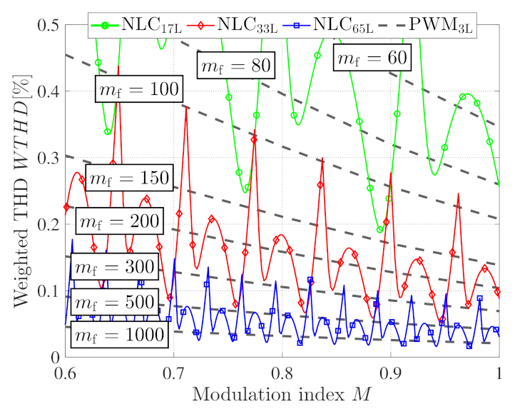
3. Weighted Total Harmonic Distortion of Higher Level NLC Waveform in Comparison to Three-Level PWM

This section should briefly quantify the quality of higher level NLC waveforms in relation to a three-level PWM waveform and its switching frequency.
The concept of the Weighted Total Harmonic Distortion (WTHD), as explained in [13], is a measure to compare the probable current quality of different voltage waveforms. To derive the expression of the WTHD, it is reasonable to start from the voltage THD expression, which can be described as
T H D V = V rms V 1 , rms 2 1 .
Without a DC component, the voltage THD expression becomes
T H D V = h = 2 V h V 1 2 .
Similar as in (17), the current THD can be expressed as
T H D I = h = 2 I h I 1 2 .
Assuming that the voltage is applied to a lossless inductive load, the current harmonics can be calculated with the help of the voltage harmonics according to
I h V h h ω 1 L with h = { 2 , 3 , 4 } .
Inserting (19) in the current THD expression given in (19), the weighted THD as a function of the voltage harmonics can be obtained according to
W T H D = 1 V 1 h = 2 V h h 2 .
According to [13], using NLC, the output harmonic components relative to the pulse transition angles can be expressed as
V out , h = 8 V DC ( L 1 ) h π cos ( h α 1 ) + + cos ( h α L 1 2 )
with only odd harmonic components occurring, corresponding to h = { 1 , 3 , 5 , } . In comparison, when operating only the NPC main stage, the output voltage components using three-level, naturally sampled, sine-triangle PWM can be described according to [13] as
V out , 1 = V DC M
and
V out , h = 4 V DC π c = 1 b = λ λ 1 2 c J 2 b 1 ( c π M ) cos ( [ c + b 1 ] π )
with
h = 2 c m f + ( 2 b 1 ) .
The expression J 2 b 1 ( c π M ) denotes the Bessel functions of the first kind with c representing the order of the carrier harmonic and b representing the order of the corresponding sideband harmonic. The number/boundary of the considered sideband harmonics is λ , which is dependent on the carrier ratio
m f = f sw f 1 ,
which is usually considered to be an integer value. In practice, also to avoid overlapping, λ is typically selected to be less than 10, because of the rapid roll-off in magnitude of the Bessel function J 2 b 1 ( c π M ) [13].
With the help of (21) and (23) the weighted THD W T H D , as described in (20), can be determined for NLC and three-level PWM relative to the modulation index M, as depicted in Figure 3. A grid-tied, 33-level inverter operated with NLC theoretically achieves a similar current quality as a three-level inverter operated with a switching frequency f sw of 5 k Hz to 25 k Hz .

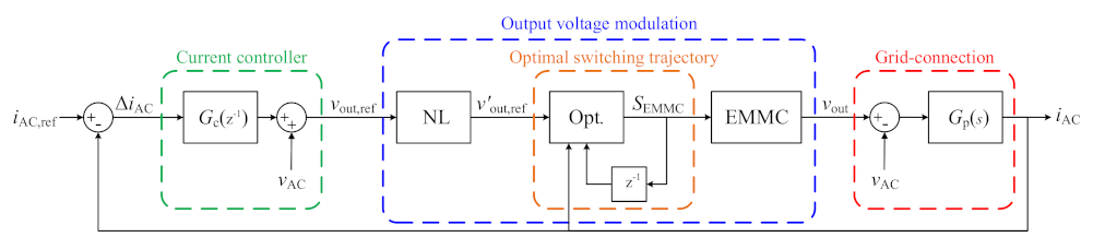
4. Current Control and Voltage Balancing of the Asymmetric Cascaded Multilevel Converter

This section gives a brief description of the current control of a grid-tied, asymmetric cascaded MLC, as shown in Figure 1. Furthermore, as a main contribution of this paper, the novel capacitor voltage balancing approach and its sensorless variant are derived.
Typically, the apparent power at the grid side, can be determined as
P AC + j Q AC = V AC · I AC .
Thus, the desired reference current for a certain apparent power can be calculated as
I AC , ref = P AC , ref j Q AC , ref V AC .
A phase-locked loop (PLL) based on a second order generator, as described in [39], shall be used to to synchronize the voltage reference frame of the inverter with the grid voltage V AC .

4.1. Current Control Using a Proportional-Resonant Controller

The suggested control scheme of the output current i AC for the grid-tied, asymmetric cascaded MLC (shown in Figure 1) is depicted in Figure 4 and explained in the following.
The derivative of the output current i AC can be expressed as
d i AC d t = R filter L filter i AC + 1 L filter ( v out v AC )
with v out as described in (5). Using the Laplace transform of (28), the current i AC in relation to the output voltage v out can be expressed in transfer-function form as
G p ( s ) = i AC v out v AC = 1 s L filter + R filter .
To control a sinusoidal single-phase current through the grid filter, a Proportional-Resonant (PR) controller, as described in [40] and emphasized in green in Figure 4, can be used. Its gain can be mathematically expressed as
G c ( s ) = v out , ref v AC Δ i AC = K p + K i s s 2 + ω 0 2
which corresponds to
G c ( s ) = K p + K i 1 s 1 + ω 0 2 1 s 1 s .
As described in [41], to discretize the controller in (31), both the forward Euler method according to
1 s T s 1 z 1
as well as the backward Euler method according to
1 s T s z z 1
can be used to implement the integrator terms and preserve the properties of the continuous PR-controller. Thus, as suggested in [41], a combination of both methods is used: forward Euler for the integrator term in the numerator and the first integrator in the denominator, and backward for the second integrator term in the denominator. The resulting controller gain G c ( s ) transformed into the z-domain is
G c ( z ) = K p + K i T s z 1 z 2 z ( 2 ω 0 2 T s 2 ) + 1 .
When using PWM, the sample time T s is typically the inverse of the switching frequency f sw at which the entire converter leg is operated. The controller parameters K i and K p can be parametrized in a similar manner as for a PI-controller, for example as described in [42,43]. To improve the performance of the current controller, the measured grid voltage v AC was used in here as a feedforward term, as can be seen in Figure 4. Hence, the current controller determines the required output voltage v out , ref , which should be modulated by the nearest discrete output voltage level v out , ref . Then, an optimal switching-state combination should be chosen and applied to actually output the required voltage.

4.2. Capacitor Voltage Balancing Using a One-Time-Step Model Predictive Control Approach

To properly control the current, the capacitor voltages must be balanced according to their nominal rating by the alternate selection of optimal switching-state combinations, as highlighted in orange in Figure 4. In the following, a model predictive control (MPC) approach with a prediction horizon of one time step, which is often referred to as one-step ahead approach [44,45], is introduced to find the optimal switching-state vector to mitigate the capacitors’ voltage imbalance within the next switching interval as much as possible.
The dynamics of the capacitors’ voltages, according to Figure 1, can be described as
d v Cap i d t = 1 C i S HB i i AC
with i = 1 , 2 , , n . The deviation of the capacitors’ voltages relative to their nominal reference voltages can be expressed as
Δ v Cap = v Cap 1 v Cap 2 v Cap n V Cap 1 , ref V Cap 2 , ref V Cap n , ref .
For each output voltage level of the EMMC, there are m switching-state combinations according to
S MLC m = S NPC , 1 S HB 1 , 1 S HB n , 1 S NPC , m S HB 1 , m S HB n , m .
Thus, considering just the switching-states of the H-bridges comprising the capacitor modules, S MLC m can be reduced to
S HB m = S HB 1 , 1 S HB n , 1 S HB 1 , m S HB n , m .
Consequently, the weighting vector W, relative to the direction of the current, to assess the effectiveness of each individual switching-state combination can be calculated as
W = + S HB m · Δ v Cap for i AC 0 S HB m · Δ v Cap for i AC < 0 .
Thus, the switching combination achieving the maximum value of W yields the optimal switching-state combination according to
max ( W ) S opt .
To understand the suggested approach better, a short example is given in the following. The output voltage v out should be V DC 2 4 and the current is positive according to i AC 0 . The number of H-bridge modules is n = 4 . This results in m = 5 possible switching-state combinations as stated in Table 1.
Presumably, the first two capacitor modules are balanced, whereas the third and fourth show a deviation of 1   V and 2 V , respectively. Thus, the weighting vector can be calculated as
W = 1 1 1 1 1 1 1 1 0 1 1 1 0 0 1 1 0 0 0 1 · 0 V 0 V 1 V 2 V
which results in
W = 1 V 1 V 1 V 3 V 2 V .
Finally, the optimal switching-state combination becomes
S opt = [ 0 0 0 0 1 ] .
A simple approach to properly dimension the capacitor sizes is given in [30]. As described in [30], the maximum voltage deviation of the converter’s output voltage occurs when all modules are inserted and it can be approximated according to
Δ V out , max = I ^ AC T s i = 1 n 1 C i
with I ^ AC and C i being the phase current’s amplitude and capacitance of the individual H-bridge modules, respectively. Thus, in comparison to the NLC approach in [30], the in here suggested approach can reduce the capacitor requirement according to (44), because the algorithm updates the switching-state combination with respect to the sample time T s and not only when step-wise changes in the output voltage occur. Since the switching-state combination is not necessarily changed after each sample period, the suggested algorithm can be categorized as an MPC approach with variable switching time instants [46].

4.3. Sensorless Capacitor Voltage Balancing Using a Dynamic Programming Approach

Considering the suggested approach in Section 4.2, a series of offline calculated, optimal switching-state combinations for each discrete output voltage level and a series of current values, positive and negative, could be used to operate the inverter with a lookup table approach without measuring the actual capacitor voltages. Thus, the offline calculated optimal switching-state combinations are sequentially applied ( z 1 ), as shown in orange in Figure 4. This approach is referred to as dynamic programming.
To keep the capacitor voltages balanced, the optimal switching-state sequences simply need to drive the average capacitor currents, sometimes referred to as current-second areas (charge), to zero. Thus, considering a variation of the converter’s displacement power factor and current amplitude, a large, intricate array of switching-state sequences would be required in theory. Although, when considering the illustration of the cell-voltage combinations in [24] [Figure 4], it becomes obvious that both the current-second and the applied voltage-second areas at steady state for any discrete output voltage become zero, if the EMMC itself is operated with a unity displacement power factor. Therefore, to reduce the required computational effort and the memory for the lookup table, the output current should be controlled to be in phase with the converter’s output voltage, as depicted in Figure 5 for grid-feeding mode, which slightly reduces the actual power factor cos( φ ). Nonetheless, this approach could affect the voltage stability when operating in grid-forming mode [47]. Consequently, an optimal switching-state sequence for each discrete voltage level when loaded with a DC current, achieving that the applied voltage-second areas of the H-bridge modules become zero, can be generated offline. The selected DC current value should preferably be as close as possible to the instantaneous current when the corresponding discrete level would be actually activated for the considered operating point. Nonetheless, if a different DC current is arbitrarily but reasonably chosen, the current-second areas become zero as well and, thus, only the capacitor voltages’ ripples are marginally affected. The suggested sensorless approach is only suitable for MLCs operated with only active power capability. Due to symmetry reasons, it is sufficient to calculate the optimal switching-state combinations for only half of the discrete output levels, e.g., for the ones creating a positive output voltage. The switching-state combinations for the negative output levels can be obtained through the multiplication of the switching-state combinations for the positive output levels and minus one. For further simplifications, in here it is suggested to use the average absolute value of the selected operating point’s AC current for all considered output levels when offline creating the switching-state combinations.
For example, Figure 6a shows the simulated capacitor voltages and the output voltage, corresponding to the fifth positive output voltage level, for a 33-level EMMC while balancing the capacitors for a certain DC current considering the approach described in Section 4.2. Thus, the switching-state combinations obtained for Figure 6a should be stored in a lookup table, and the approach should be repeated for all remaining positive voltage levels. When operating the inverter and generating an AC output voltage, a switching-state combination is sequentially chosen from the stored lookup tables for each of the desired reference voltage levels v out , ref . For example, assuming ideally balanced capacitor voltages, Figure 6b shows the output voltages of the asymmetric MLC and the individual converter stages corresponding to a fundamental output voltage of V out , 1 = 330   V .
For the depicted switching pattern, the average switching frequency of the NPC main stage corresponds to about f ¯ sw , NPC 950 Hz , while the switching frequency of the individual H-bridges is about twice the switching frequency of the NPC module according to f ¯ sw , HB 2 f ¯ sw , NPC . Since the converter allows for bidirectional power flow, the described approach can be applied in a similar way when operating the converter as an electronic load.

5. Stability of the Sensorless, Dynamic Programming Approach

It is assumed that for some desired steady state current trajectory i AC , ref the required switching-state sequences S NPC ( des ) and S HB i ( des ) , for achieving the necessary output voltage v out = V DC S NPC ( des ) + i = 1 n S HB i ( des ) v Cap i , can be accurately generated. This may eventually require a fine time resolution (or a relative high switching frequency). The developed converter system experimentally displays the following behavior: when driven by such an optimal switching-state sequence, independent of the initial state, the system eventually reaches the desired current trajectory. The goal of this section is proving such observed behavior.
The system considered is described by the current i AC and n capacitor voltages v Cap i , which represent together the state vector. The deviation between the actual state and the desired reference trajectory is described by
Δ i AC = i AC i AC , ref
and
Δ v Cap i = v Cap i v Cap i , ref .
The dynamics of the actual and the reference current, both driven by the same optimal switching-state sequences S NPC ( des ) and S HB i ( des ) , are given by
d i AC d t = R filter L filter i AC + 1 L filter ( V DC S NPC ( des ) + i = 1 n S HB i ( des ) v Cap i v AC )
and
d i AC , ref d t = R filter L filter i AC , ref + 1 L filter ( V DC S NPC ( des ) + i = 1 n S HB i ( des ) v Cap i , ref v AC )
respectively, such that the current error’s dynamics become
d Δ i AC d t = R filter L filter Δ i AC + 1 L filter i = 1 n S HB i ( des ) Δ v Cap i .
Analogously, the dynamics of the actual and the reference capacitor voltages, both again driven by the same optimal switching-state sequences S NPC ( des ) and S HB i ( des ) , are respectively given by
d v Cap i d t = 1 C i S HB i ( des ) i AC
and
d v Cap i , ref d t = 1 C i S HB i ( des ) i AC , ref
leading to the following dynamics for the capacitors’ voltage errors
d Δ v Cap i d t = 1 C i S HB i ( des ) Δ i AC .
The proof of the observed experimental behavior mentioned at the beginning of this section is easily shown by introducing the following Lyapunov function V = V ( Δ i AC , Δ v Cap i ) according to
V = L filter 2 ( Δ i AC ) 2 + i = 1 n C i 2 ( Δ v Cap i ) 2
analogous in form to the total energy stored in the inductor and capacitors of the system, although now referred to the deviations from the desired trajectory. This Lyapunov function V is strictly positive as long as the errors Δ i AC and/or Δ v Cap i do not vanish. As a result of the dynamics (49) and (52) function V is a nonincreasing function with time
d V d t = R filter Δ i AC 2 .
This time derivative is nevertheless only negative semidefinite, since the Lyapunov function V = V ( Δ i AC , Δ v Cap i ) depends on all the n + 1 dynamic variables, but its time derivative does only depend on one single variable ( Δ i AC ). Consequently, the original Lyapunov theorem is of no use for proving the asymptotic stability behavior Δ i AC , Δ v Cap i t 0 and the more general Krassowski–LaSalle invariance principle [48,49] is required. According to this latter principle, the dynamics asymptotically converge to some trajectory of the considered equations of motion (49) and (52), which simultaneously satisfied d V / d t = 0 ; however, a constant stationary point of the equations of motion is also a (trivial) trajectory remaining on the same value during the whole time evolution. A vanishing time derivative of the Lyapunov function yields
d V d t = R filter Δ i AC 2 = 0 Δ i AC = 0 ,
which according to (49) leads to i = 1 n S HB i ( des ) Δ v Cap i = 0 , although not to the separated vanishing of each single Δ v Cap i . Since nevertheless the switching-state sequence values S HB i ( des ) change all the time, once Δ i AC = 0 is achieved, the probability of satisfying condition i = 1 n S HB i ( des ) Δ v Cap i = 0 with varying S HB i ( des ) (and also changing Δ v Cap i ) is very low, particularly for a relative high number of capacitor modules: the only solution of condition i = 1 n S HB i ( des ) Δ v Cap i = 0 under these conditions is therefore Δ v Cap i = 0 for each single capacitor. Since this only solution Δ i AC = 0 = Δ v Cap i is also a trajectory of the equations of motion, the Krassowski–LaSalle invariance principle shows that the system cannot get “stuck” at any other trajectory than such stationary point. Hence, when driving the converter system with the optimal switching-state sequences corresponding to some desired reference trajectory, such trajectory is asymptotically reached
i AC t i AC , ref and v Cap i t v Cap i , ref .
The main ingredient in the previous proof is the existence of a nonvanishing (positive) resistance R filter which constantly dissipates power, and thus, ensures the decreasing of the Lyapunov function value.

6. Measurements

To verify the effectiveness and the stability of the derived one-step ahead balancing algorithm and its sensorless variant (described above), a laboratory, 33-level converter is used, as can be seen in Figure 7. It is based on the commercially available converter modules from Imperix Ltd. and it comprises an NPC main stage [50] and four H-bridge modules [51]. The entire control and balancing algorithm is implemented in the B-Box RCP control unit [52] of Imperix Ltd. The DC inputs of the NPC module and each of the H-bridges are attached with a 517 μ F and a 5 m F capacitor bank (electrolytic), respectively. The selected DC link voltage rating is V DC = 350   V , using unidirectional power supplies, and the chosen grid filter’s inductance rating is about 30 m H ( L filter = 28.8   mH , R filter = 0.2   Ω and I rat , rms = 30   A ). Here, the design of the converter and the grid filter is not part of this paper’s scope. Especially, the size of the grid filter seems rather large, but it is chosen for simplicity. The inductance rating for an LCL-filter ( 60 d B damping per decade) with a similar damping effect could be about 100 times smaller, corresponding to about 300 μ H . The used charging resistors have a total resistance of R charging = 80   Ω . The entire converter leg is operated with a sampling frequency of f s = 5   kHz , which results in an actual average switching frequency, similar as described in Section 4.3, of about f ¯ sw , NPC 950 Hz and f ¯ sw , HB 2 f ¯ sw , NPC for the NPC stage and the H-bridges, respectively. For the experimental verification, all waveforms are captured with an oscilloscope.

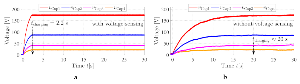
6.1. Capacitor Precharging

Before operating the converter in grid-feeding mode, the capacitors must be charged up using the suggested charging resistance R charging . During the charging process, the reference output voltage v out , ref should be set to v AC . When already using the current controller, the reference current i AC , ref should be set to zero. Figure 8a,b show the start-up charging of the H-bridges’ capacitors when operating the inverter with and without the voltage sensing, respectively.
Since the sensorless approach utilizes a switching-pattern, which was generated only for the actual operating point of I ^ AC = 10   A , it takes about 20 s until the capacitors have reached their nominal reference voltages. This in turn verifies the stability described in Section 5. On the contrary, when using the capacitor voltages as a feedback, the nominal reference voltages are already reached after about 2.2   s . Hence, the dynamic response, using the sensorless approach, is compromised.

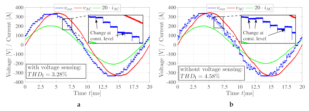
6.2. Operation in Grid-Feeding Mode

When the H-bridges’ capacitors are completely charged up, the charging resistor R charging can be bypassed via the contactor. Subsequently, the converter can be operated according to Figure 5, feeding active power to the grid. Figure 9a,b show the grid voltage v AC , the converter output voltage v out and the output current i AC for one electrical period with and without the sensing of the capacitor voltages, respectively. The current’s magnitude is controlled to be I ^ AC = 10   A , which results in a fundamental output voltage of about V out , 1 = 330   V . Thus, the converter is feeding about 1.65   k W to the grid. The phase shift angle φ between the grid voltage V AC and I AC is about 16.5   , leading (over excited). This corresponds to a power factor of about cos ( φ ) = 0.96 . Figure 9a shows that, due to the feedback of the capacitor voltages, the discrete output voltage levels are properly modulated while altering the switching-state combinations. Thus, the current THD becomes about 3.28 . On the contrary, when using the sensorless approach, the capacitor voltages slightly deviate during the operation. This is due to the fact that the nonlinear effects, such as the voltage drop across the IGBTs, the different self-discharge rates or the dead-time, are neglected during the offline generation of the optimal switching-state combinations. Thus, the discrete output voltage levels are slightly distorted while altering the switching-state combinations. This in turn results in an increased current THD of about 4.58 .
As described in the IEEE standard 519-2014 [53], “IEEE Recommended Practice and Requirements for Harmonic Control in Electric Power Systems”, a maximum current THD of up to 20 (depending on the connection point’s Thévnin impedance) and up to 5 is recommended for power consuming loads and power generating units, respectively. Consequently, the suggested control approach, including its sensorless variant, achieved a power-system-compliant current THD quality (< 5 ).
Moreover, Figure 10a,b depict the harmonic components of the in Figure 9a,b depicted voltage and current waveforms, respectively. The depicted inset-figures in Figure 10a,b depict the harmonic components of the voltage and current waveforms in relation to their corresponding fundamental component and, in addition, the permissible, relative limits of the current harmonics according to the IEEE standard 519-2014 [53] are depicted by the green dashed line. All measured current harmonics comply with the specified limits. For both cases, with and without the sensing of the capacitor voltages, the third harmonic current component is the largest. Thus, the current THD value T H D I is mainly driven by the third harmonic, which is caused by the third harmonic component of the inverter output voltage. Consequently, to improve the current quality further, it might be reasonable to implement a harmonic reduction technique, such as presented in [54,55] or [56], to decrease the third harmonic current component. Furthermore, triplen harmonics, such as the third harmonic, would not cause any currents if the inverter would be operated in an ungrounded three-phase system.

7. Conclusions

Based on the concept of the weighted THD of MLIs’ output voltage waveform, it was shown that a grid-tied ( 50 Hz ) MLI with 33 discrete output voltages levels, operated with NLC, can presumably achieve a similar current THD as a single-phase H-bridge converter operated with a switching frequency of 25 k Hz (three-level PWM). To utilize this advantage, binary asymmetric voltage levels can be used for MLIs’ floating capacitor modules to reduce the number of required H-bridge modules.
This paper presented a novel capacitor voltage balancing approach applicable for cascaded multilevel converters with only one DC supply per phase and asymmetric capacitor voltages, tiered by a factor of two (binary asymmetric). Using a simple one-step ahead MPC approach, an optimal switching-state combination is mathematically determined among all redundant switching combinations to balance the capacitor voltages as quickly as possible. Furthermore, using the suggested optimal one-step ahead MPC approach, a series of offline calculated switching-state sequences for each discrete output voltage level can be used as lookup tables to operate the MLC without actually measuring (sensorless) the capacitor voltages. Using a Lyapunov function candidate, which is based on the energy stored in the grid filter’s inductor and the H-bridges’ capacitors, and considering LaSalle’s invariance principle, the proposed sensorless control approach is asymptotically stable, and thus, the capacitor voltages and the grid current converge over time to their desired references.
To experimentally verify the effectiveness and the stability of the presented one-step ahead balancing algorithm and its sensorless variant, a laboratory converter with four H-bridge stages, ideally achieving 33 discrete output voltage levels, was operated in grid-tied mode. Using a charging resistor during startup, the capacitor voltages converge to their desired reference levels, whereas the required charging time was increased from 2.2   s to 20 s when using the suggested sensorless control approach. The converter was operated with a sampling frequency of 5 k Hz , which resulted in an actual switching frequency of 950 Hz and 2 k Hz for the NPC stage and the individual H-bridge modules, respectively. For the chosen operating point ( I ^ AC = 10   A ) of the setup, the presented sensorless approach achieved a current THD T H D I of about 4.58%, which is slightly increased in comparison to 3.28% when operating the converter with the voltage sensors. Nonetheless, it was verified that the suggested sensorless approach is asymptotically stable and can be used in practice, although the dynamic response of the system and the output current quality is enhanced when using the voltage sensors.
So far, only the active power capability of the sensorless approach was considered. Thus, in a future work, the algorithm could be extended to control also the reactive power.

Author Contributions

Conceptualization, M.K., A.K., J.-L.M.-L., T.W. and R.E.; methodology, M.K., A.K., J.-L.M.-L., J.E., J.B., F.S., T.T., A.L., R.M., T.W. and R.E.; software, M.K., A.K., J.E., J.B., F.S.; validation, M.K., A.K., J.E., J.B., F.S.; formal analysis, M.K., A.K., J.-L.M.-L., J.E., J.B., F.S., T.T., A.L., R.M., T.W. and R.E.; investigation, M.K., A.K., J.-L.M.-L., J.E., J.B., F.S., T.T., A.L., R.M., T.W. and R.E.; resources, M.K., T.T., T.W. and R.E.; writing—original draft preparation, M.K., A.K., J.E., J.B.; writing—review and editing, M.K., A.K., J.-L.M.-L., J.E., J.B., F.S., T.T., A.L., R.M., T.W. and R.E.; visualization, M.K., A.K., J.E., J.B., F.S.; supervision, T.T., R.M., T.W. and R.E.; project administration, M.K., A.L., T.T., T.W. and R.E.; funding acquisition, M.K., T.T., T.W. and R.E. All authors have read and agreed to the published version of the manuscript.

Funding

This research is funded by MORE/ELAPSED as part of dtec.bw - Digitalization and Technology Research Center of the Bundeswehr which we gratefully acknowledge. Furthermore, the financial support provided by the Swedish Energy Agency (Energimyndigheten) is gratefully acknowledged as well.

Conflicts of Interest

The authors declare no conflict of interest. The funders had no role in the design of the study; in the collection, analyses, or interpretation of data; in the writing of the manuscript, or in the decision to publish the results.

References

  1. Lesnicar, A.; Marquardt, R. An innovative modular multilevel converter topology suitable for a wide power range. In Proceedings of the 2003 IEEE Bologna Power Tech Conference Proceedings, Bologna, Italy, 23–26 June 2003; Volume 3, p. 6. [Google Scholar]
  2. Behrouzian, E.; Bongiorno, M. Investigation of Negative-Sequence Injection Capability of Cascaded H-Bridge Converters in Star and Delta Configuration. IEEE Trans. Power Electron. 2017, 32, 1675–1683. [Google Scholar] [CrossRef]
  3. Tolbert, L.M.; Peng, F.Z.; Habetler, T.G. Multilevel converters for large electric drives. IEEE Trans. Ind. Appl. 1999, 35, 36–44. [Google Scholar] [CrossRef] [Green Version]
  4. Corzine, K.; Familiant, Y. A new cascaded multilevel H-bridge drive. IEEE Trans. Power Electron. 2002, 17, 125–131. [Google Scholar] [CrossRef]
  5. Ma, M.; Hu, L.; Chen, A.; He, X. Reconfiguration of Carrier-Based Modulation Strategy for Fault Tolerant Multilevel Inverters. IEEE Trans. Power Electron. 2007, 22, 2050–2060. [Google Scholar] [CrossRef]
  6. Kersten, A.; Oberdieck, K.; Bubert, A.; Neubert, M.; Grunditz, E.; Thiringer, T.; De Doncker, R.W. Fault Detection and Localization for Limp Home Functionality of Three-Level NPC Inverters with Connected Neutral Point for Electric Vehicles. IEEE Trans. Transp. Electrif. 2019, 5, 416–432. [Google Scholar] [CrossRef]
  7. Kersten, A.; Oberdieck, K.; Gossmann, J.; Bubert, A.; Loewenherz, R.; Neubert, M.; Thiringer, T.; De Doncker, R. Measuring and Separating Conducted Three-Wire Emissions from a Fault-Tolerant, NPC Propulsion Inverter with a Split-Battery using Hardware Separators based on HF Transformers. IEEE Trans. Power Electron. 2020, 36, 378–390. [Google Scholar] [CrossRef]
  8. Zhang, H.; Yang, L.; Wang, S.; Puukko, J. Common-Mode EMI Noise Modeling and Reduction With Balance Technique for Three-Level Neutral Point Clamped Topology. IEEE Trans. Ind. Electron. 2017, 64, 7563–7573. [Google Scholar] [CrossRef]
  9. Chang, F.; Ilina, O.; Lienkamp, M.; Voss, L. Improving the Overall Efficiency of Automotive Inverters Using a Multilevel Converter Composed of Low Voltage Si mosfets. IEEE Trans. Power Electron. 2019, 34, 3586–3602. [Google Scholar] [CrossRef]
  10. Kersten, A.; Grunditz, E.; Thiringer, T. Efficiency of Active Three-Level and Five-Level NPC Inverters Compared to a Two-Level Inverter in a Vehicle. In Proceedings of the 2018 20th European Conference on Power Electronics and Applications (EPE’18 ECCE Europe), Riga, Latvia, 17–21 September 2018; pp. P.1–P.9. [Google Scholar]
  11. Kersten, A.; Kuder, M.; Grunditz, E.; Geng, Z.; Wikner, E.; Thiringer, T.; Weyh, T.; Eckerle, R. Inverter and Battery Drive Cycle Efficiency Comparisons of CHB and MMSP Traction Inverters for Electric Vehicles. In Proceedings of the 2019 21st European Conference on Power Electronics and Applications (EPE ’19 ECCE Europe), Genova, Italy, 3–5 September 2019; pp. P.1–P.12. [Google Scholar] [CrossRef]
  12. Zhang, Y.; Adam, G.P.; Lim, T.C.; Finney, S.J.; Williams, B.W. Hybrid Multilevel Converter: Capacitor Voltage Balancing Limits and its Extension. IEEE Trans. Ind. Inform. 2013, 9, 2063–2073. [Google Scholar] [CrossRef]
  13. Holmes, D.G.; Lipo, T.A. Pulse Width Modulation for Power Converters: Principles and Practice; John Wiley & Sons: Hoboken, NJ, USA, 2003; Volume 18. [Google Scholar]
  14. Ruderman, A.; Schlosberg, S. A hybrid asymmetric cascaded multilevel inverter comprising high resolution and symmetric low resolution parts. In Proceedings of the 2008 IEEE 25th Convention of Electrical and Electronics Engineers in Israel, Eilat, Israel, 3–5 December 2008; pp. 21–25. [Google Scholar] [CrossRef]
  15. Thielemans, S.; Ruderman, A.; Reznikov, B.; Melkebeek, J. Improved Natural Balancing With Modified Phase-Shifted PWM for Single-Leg Five-Level Flying-Capacitor Converters. IEEE Trans. Power Electron. 2012, 27, 1658–1667. [Google Scholar] [CrossRef] [Green Version]
  16. Ruderman, A.; Reznikov, B.; Thielemans, S. Four-level H-bridge flying capacitor converter voltage balance dynamics analysis. In Proceedings of the 2009 35th Annual Conference of IEEE Industrial Electronics, Porto, Portugal, 3–5 November 2009; pp. 498–503. [Google Scholar] [CrossRef]
  17. Mariethoz, S. Systematic Design of High-Performance Hybrid Cascaded Multilevel Inverters With Active Voltage Balance and Minimum Switching Losses. IEEE Trans. Power Electron. 2013, 28, 3100–3113. [Google Scholar] [CrossRef]
  18. Mademlis, G.; Liu, Y.; Saadat, N. Combined voltage balancing techniques of the DC link in five-level medium voltage NPC back-to-back converters for offshore renewable generation. In Proceedings of the 2017 19th European Conference on Power Electronics and Applications (EPE’17 ECCE Europe), Warsaw, Poland, 11–14 September 2017; pp. P.1–P.10. [Google Scholar]
  19. He, L.; Sun, J.; Lin, Z.; Cheng, B. Capacitor-Voltage Self-Balance Multilevel Inverter with Unequal Amplitude Carrier-Based APODPWM. IEEE Trans. Power Electron. 2021, 36, 14002–14013. [Google Scholar] [CrossRef]
  20. Wheeler, P.W.; Empringham, L.; Gerry, D. Improved output waveform quality for multi-level H-bridge chain converters using unequal cell voltages. In Proceedings of the 2000 Eighth International Conference on Power Electronics and Variable Speed Drives (IEE Conf. Publ. No. 475), London, UK, 18–19 September 2000; pp. 536–540. [Google Scholar]
  21. Babaei, E.; Hosseini, S.H. Charge balance control methods for asymmetrical cascade multilevel converters. In Proceedings of the 2007 International Conference on Electrical Machines and Systems (ICEMS), Seoul, Korea, 8–11 October 2007; pp. 74–79. [Google Scholar]
  22. Veenstra, M.; Rufer, A. Control of a hybrid asymmetric multilevel inverter for competitive medium-voltage industrial drives. IEEE Trans. Ind. Appl. 2005, 41, 655–664. [Google Scholar] [CrossRef]
  23. Fuentes, C.D.; Rojas, C.A.; Renaudineau, H.; Kouro, S.; Perez, M.A.; Meynard, T. Experimental Validation of a Single DC Bus Cascaded H-Bridge Multilevel Inverter for Multistring Photovoltaic Systems. IEEE Trans. Ind. Electron. 2017, 64, 930–934. [Google Scholar] [CrossRef]
  24. Monteiro, A.P.; Jacobina, C.B.; Méllo, J.P.R.A.; de Freitas, N.B.; Matias, R.R. Capacitor Voltage Balancing for Single-Phase Asymmetric Cascaded H-Bridge Inverters. IEEE Trans. Ind. Appl. 2020, 56, 5129–5141. [Google Scholar] [CrossRef]
  25. Zambra, D.A.B.; Rech, C.; Pinheiro, J.R. Comparison of Neutral-Point-Clamped, Symmetrical, and Hybrid Asymmetrical Multilevel Inverters. IEEE Trans. Ind. Electron. 2010, 57, 2297–2306. [Google Scholar] [CrossRef]
  26. Mariethoz, S. Design and Control of High-Performance Modular Hybrid Asymmetrical Cascade Multilevel Inverters. IEEE Trans. Ind. Appl. 2014, 50, 4018–4027. [Google Scholar] [CrossRef]
  27. Kuder, M.; Kersten, A.; Bergmann, L.; Eckerle, R.; Helling, F.; Weyh, T. Exponential Modular Multilevel Converter for Low Voltage Applications. In Proceedings of the 2019 21st European Conference on Power Electronics and Applications (EPE ’19 ECCE Europe), Genova, Italy, 3–5 September 2019; pp. P.1–P.11. [Google Scholar] [CrossRef]
  28. Zygmanowski, M.; Michalak, J.; Grzesik, B. DC-link voltage balancing method for a hybrid asymmetric multilevel converter. In Proceedings of the 2013 15th European Conference on Power Electronics and Applications (EPE), Lille, France, 2–6 September 2013; pp. 1–10. [Google Scholar] [CrossRef]
  29. Vasu, R.; Chattopadhyay, S.K.; Chakraborty, C. Asymmetric Cascaded H-Bridge Multilevel Inverter With Single DC Source per Phase. IEEE Trans. Ind. Electron. 2020, 67, 5398–5409. [Google Scholar] [CrossRef]
  30. Ziaeinejad, S.; Sangsefidi, Y.; Mehrizi-Sani, A. A Generalized Switching Strategy and Capacitor Sizing Algorithm for Granular Multilevel Converters. IEEE Trans. Ind. Electron. 2018, 65, 4443–4453. [Google Scholar] [CrossRef]
  31. Moeini, A.; Wang, S. A DC Link Sensor-Less Voltage Balancing Technique for Cascaded H-Bridge Multilevel Converters with Asymmetric Selective Harmonic Current Mitigation-PWM. IEEE Trans. Power Electron. 2018, 33, 7571–7581. [Google Scholar] [CrossRef]
  32. Vahedi, H.; Al-Haddad, K. Single-DC-source five-level CHB inverter with sensor-less voltage balancing. In Proceedings of the IECON 2015—-41st Annual Conference of the IEEE Industrial Electronics Society, Yokohama, Japan, 9–12 November 2015. [Google Scholar] [CrossRef]
  33. Vahedi, H.; Labbé, P.; Al-Haddad, K. Sensor-Less Five-Level Packed U-Cell (PUC5) Inverter Operating in Stand-Alone and Grid-Connected Modes. IEEE Trans. Ind. Inform. 2016, 12, 361–370. [Google Scholar] [CrossRef]
  34. Kersten, A.; Kuder, M.; Marques-Lopez, J.L.; Schwitzgebel, F.; Thiringer, T.; Marquardt, R.; Weyh, T.; Eckerle, R. Sensorless Capacitor Voltage Balancing of a Grid-Tied, Single-Phase Hybrid Multilevel Converter with Asymmetric Capacitor Voltages using Dynamic Programming. In Proceedings of the IECON 2020 the 46th Annual Conference of the IEEE Industrial Electronics Society, Singapore, 18–21 October 2020; pp. 4288–4293. [Google Scholar] [CrossRef]
  35. Haghbin, S.; Thiringer, T.; Alatalo, M.; Karlsson, R. An LCL filter with an active compensation for a fast charger station. In Proceedings of the 2017 IEEE International Conference on Environment and Electrical Engineering and 2017 IEEE Industrial and Commercial Power Systems Europe (EEEIC/I CPS Europe), Milan, Italy, 6–9 June 2017; pp. 1–5. [Google Scholar]
  36. Liserre, M.; Blaabjerg, F.; Hansen, S. Design and control of an LCL-filter-based three-phase active rectifier. IEEE Trans. Ind. Appl. 2005, 41, 1281–1291. [Google Scholar] [CrossRef]
  37. IEEE. IEEE Guide for Smart Grid Interoperability of Energy Technology and Information Technology Operation with the Electric Power System (EPS), End-Use Applications, and Loads; IEEE Std 519-2014 (Revision of IEEE Std 519-1992); IEEE: Piscataway, NJ, USA, 2014; pp. 1–126. [CrossRef]
  38. Lee, C.T.; Hsu, C.W.; Cheng, P.T. A Low-Voltage Ride-Through Technique for Grid-Connected Converters of Distributed Energy Resources. IEEE Trans. Ind. Appl. 2011, 47, 1821–1832. [Google Scholar] [CrossRef]
  39. Ciobotaru, M.; Teodorescu, R.; Blaabjerg, F. A new single-phase PLL structure based on second order generalized integrator. In Proceedings of the 2006 37th IEEE Power Electronics Specialists Conference, Jeju, Korea, 18–22 June 2006; pp. 1–6. [Google Scholar] [CrossRef]
  40. Cha, H.; Vu, T.K.; Kim, J.E. Design and control of Proportional-Resonant controller based Photovoltaic power conditioning system. In Proceedings of the 2009 IEEE Energy Conversion Congress and Exposition, San Jose, CA, USA, 20–24 September 2009; pp. 2198–2205. [Google Scholar]
  41. Richter, S.A.; De Doncker, R.W. Digital proportional-resonant (PR) control with anti-windup applied to a voltage-source inverter. In Proceedings of the 2011 14th European Conference on Power Electronics and Applications, Birmingham, UK, 30 August–1 September 2011; pp. 1–10. [Google Scholar]
  42. Harnefors, L. Control of Variable-Speed Drives; Applied Signal Processing and Control, Department of Electronics, Mälardalen University: Västerås, Sweden, 2002. [Google Scholar]
  43. Sharifabadi, K.; Harnefors, L.; Nee, H.P.; Norrga, S.; Teodorescu, R. Design, Control, and Application of Modular Multilevel Converters for HVDC Transmission Systems; John Wiley & Sons: Hoboken, NJ, USA, 2016. [Google Scholar]
  44. Kim, S.K.; Park, C.R.; Lee, Y.I. One-step ahead model predictive controller of three-phase inverter for uninterruptible power supply applications. In Proceedings of the 2014 IEEE Applied Power Electronics Conference and Exposition-APEC 2014, Fort Worth, TX, USA, 16–20 March 2014; pp. 2735–2740. [Google Scholar] [CrossRef]
  45. Benzaquen, J.; Fateh, F.; Shadmand, M.B.; Mirafzal, B. One-Step-Ahead Adaptive Control Scheme for Active Rectifiers in Wild Frequency Applications. In Proceedings of the 2019 IEEE Applied Power Electronics Conference and Exposition (APEC), Anaheim, CA, USA, 17–21 March 2019; pp. 588–593. [Google Scholar] [CrossRef]
  46. Karamanakos, P.; Liegmann, E.; Geyer, T.; Kennel, R. Model Predictive Control of Power Electronic Systems: Methods, Results, and Challenges. IEEE Open J. Ind. Appl. 2020, 1, 95–114. [Google Scholar] [CrossRef]
  47. Kermani, M. Transient voltage and frequency stability of an isolated microgrid based on energy storage systems. In Proceedings of the 2016 IEEE 16th International Conference on Environment and Electrical Engineering (EEEIC), Florence, Italy, 7–10 June 2016; pp. 1–5. [Google Scholar] [CrossRef]
  48. LaSalle, J. The extent of asymptotic stability. Proc. Natl. Acad. Sci. USA 1960, 46, 363. [Google Scholar] [CrossRef] [Green Version]
  49. Chen, F.C.; Khalil, H.K. Adaptive control of nonlinear systems using neural networks. Int. J. Control 1992, 55, 1299–1317. [Google Scholar] [CrossRef]
  50. Imperix Ltd. PEN8018-NPC Building Block. Available online: https://cdn.imperix.com/wp-content/uploads/document/PEN8018.pdf (accessed on 29 September 2020).
  51. Imperix Ltd. PEH2015-Full Bridge Building Block. Available online: https://cdn.imperix.com/wp-content/uploads/document/PEH2015.pdf (accessed on 29 September 2020).
  52. Imperix Ltd. B-Box RCP-RAPID Prototyping Controller. Available online: https://cdn.imperix.com/wp-content/uploads/document/B-Box_Datasheet.pdf (accessed on 12 November 2020).
  53. IEEE. IEEE Recommended Practice and Requirements for Harmonic Control in Electric Power Systems; IEEE Std 519-2014 (Revision of IEEE Std 519-1992); IEEE: Piscataway, NJ, USA, 2014; pp. 1–29. [Google Scholar] [CrossRef]
  54. Marzoughi, A.; Imaneini, H. An optimal selective harmonic mitigation for cascaded H-bridge converters. In Proceedings of the 2012 11th International Conference on Environment and Electrical Engineering, Venice, Italy, 18–25 May 2012; pp. 752–757. [Google Scholar] [CrossRef]
  55. Kersten, A.; Kuder, M.; Singer, A.; Han, W.; Thiringer, T.; Weyh, T.; Eckerle, R. Elimination/Mitigation of Output Voltage Harmonics for Multilevel Converters Operated at Fundamental Switching Frequency using Matlab’s Genetic Algorithm Optimization. In Proceedings of the 2020 22nd European Conference on Power Electronics and Applications (EPE’20 ECCE Europe), Lyon, France, 7–11 September 2020; pp. 1–12. [Google Scholar] [CrossRef]
  56. Du, Z.; Tolbert, L.M.; Ozpineci, B.; Chiasson, J.N. Fundamental Frequency Switching Strategies of a Seven-Level Hybrid Cascaded H-Bridge Multilevel Inverter. IEEE Trans. Power Electron. 2009, 24, 25–33. [Google Scholar] [CrossRef] [Green Version]
Figure 1. Grid-connected, single-phase asymmetric MLC arrangement, using an NPC module as main stage and n series-connected H-bridges, with charging resistor R charging .
Energies 15 00575 g001
Figure 2. Desired, modulated reference voltage waveform v out , ref using nearest-level control for a 17-level converter and a modulation index M = 0.95 .
Energies 15 00575 g002
Figure 3. Weighted THD W T H D relative to the modulation index M when using NLC, computed for 17, 33, and 65 output voltage levels, and three-level PWM for different carrier frequency ratios m f .
Energies 15 00575 g003
Figure 4. Current control scheme of asymmetric MLC.
Energies 15 00575 g004
Figure 5. Vector diagram of controlled current I AC relative to converter voltage V out and grid voltage V AC when operating converter in grid-feeding mode without capacitor voltage sensing.
Energies 15 00575 g005
Figure 6. Switching-state sequence generation: (a) simulated capacitor voltage oscillations using the suggested one-time-step MPC approach for one discrete output voltage level and (b) generated switching-state sequence for one electrical period.
Energies 15 00575 g006
Figure 7. (a) Converter modules and grid filter. (b) Actual laboratory arrangement of the 33-level, grid-tied asymmetric MLC.
Energies 15 00575 g007
Figure 8. Measured charging of H-bridges’ capacitors during converter startup using additional charging resistance R charging = 80   Ω (a), with sensing and (b) without sensing of the capacitor voltages.
Energies 15 00575 g008
Figure 9. Measured operation of 33-level asymmetric MLC, controlling a grid current of I ^ AC = 10   A , (a) with and (b) without sensing of the capacitor voltages.
Energies 15 00575 g009
Figure 10. Harmonic components of measured voltage and current waveforms given in Figure 9, (a) with and (b) without sensing of the capacitor voltages.
Energies 15 00575 g010
Table 1. Switching-state combinations for v out = V DC 2 4 and n = 4 , which gives m = 5 possible combinations.
S NPC V DC 2 0 S HB 1 V DC 2 1 S HB 2 V DC 2 2 S HB 3 V DC 2 3 S HB 4 V DC 2 4
1−1−1−1−1
01−1−1−1
001−1−1
0001−1
00001
Publisher’s Note: MDPI stays neutral with regard to jurisdictional claims in published maps and institutional affiliations.

