
Frequency and Voltage Control Techniques through Inverter-Interfaced Distributed Energy Resources in Microgrids: A Review


Abstract
:1. Introduction
2. Communication-Based Control Strategies for Parallel Inverters
2.1. Concentrated Control
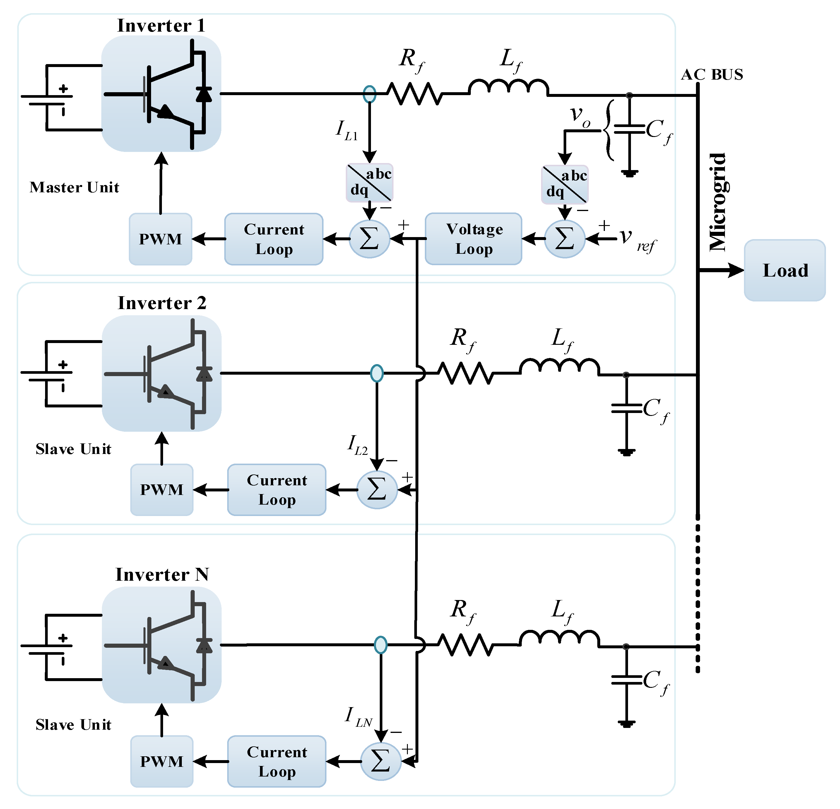
2.2. Master–Slave Method
2.3. Current Distribution Control
- (1)
- (2)
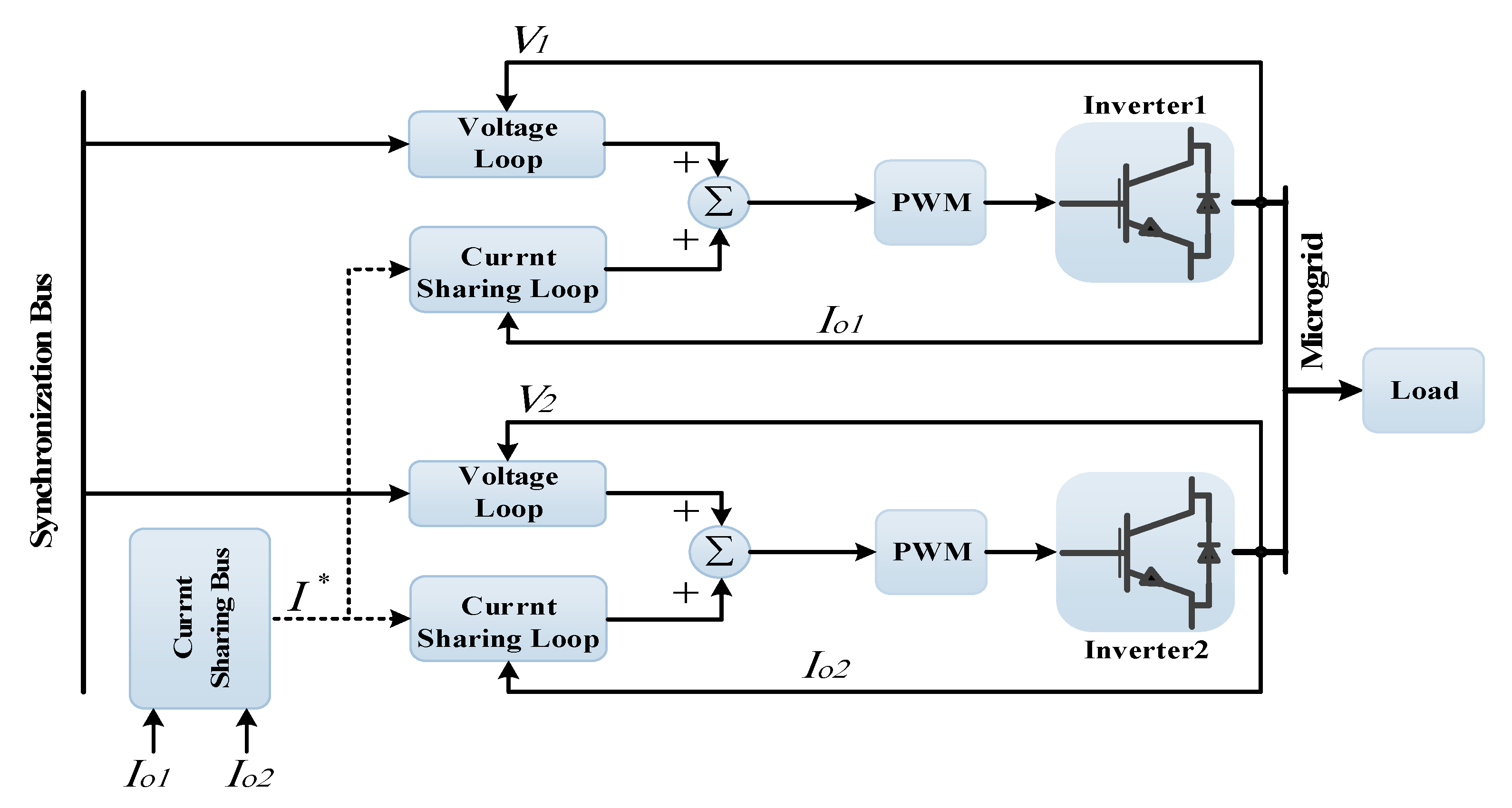
- The average and instantaneous current control techniques are based on inter-unit communication, in contrast to the master–slave control method. This technique requires reference synchronization for the voltage and current at the point of common coupling (PCC) to have better current sharing and voltage regulation. Figure 5 shows the structure of this control method. Yet, this technique reduces the flexibility and reliability of the system [16].
- (3)
- The one-cycle control method combines a vector and bipolar operation with an extra simple communication link among the parallel inverters. Thus, the circulating current among parallel inverters can be reduced. This control technique has advantages, such as constant switching frequency, no reference calculation, simple system wiring, and lack of need for multipliers, while providing more flexibility [4,57].
- (4)
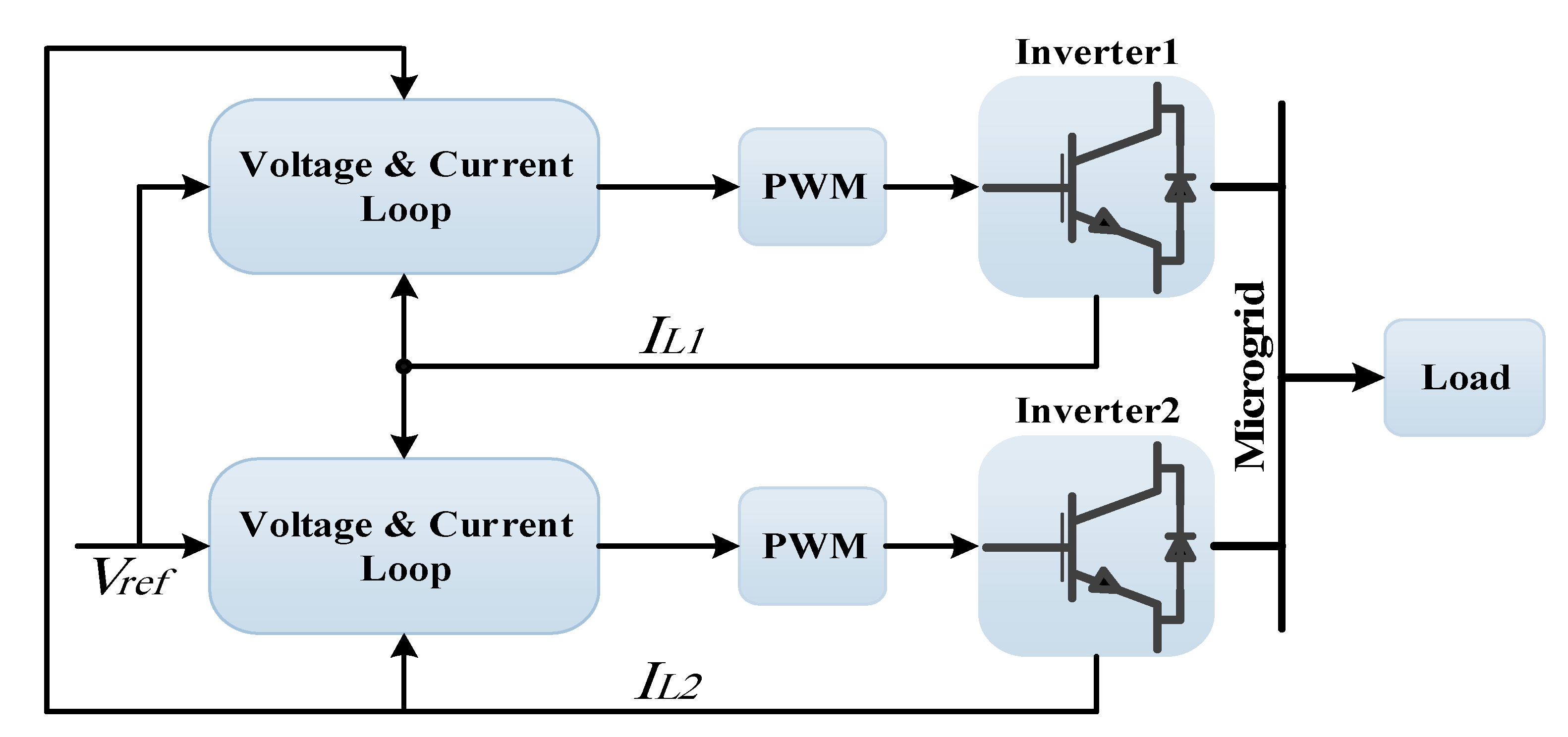
- The circular chain control method, which is also known as the 3C method, is illustrated in Figure 6. In this technique, each unit is connected in a circular configuration that uses internal current control to track the inductor current of consecutive parallel inverter units for achieving equal current distribution among the parallel inverters [31,44].
- (5)
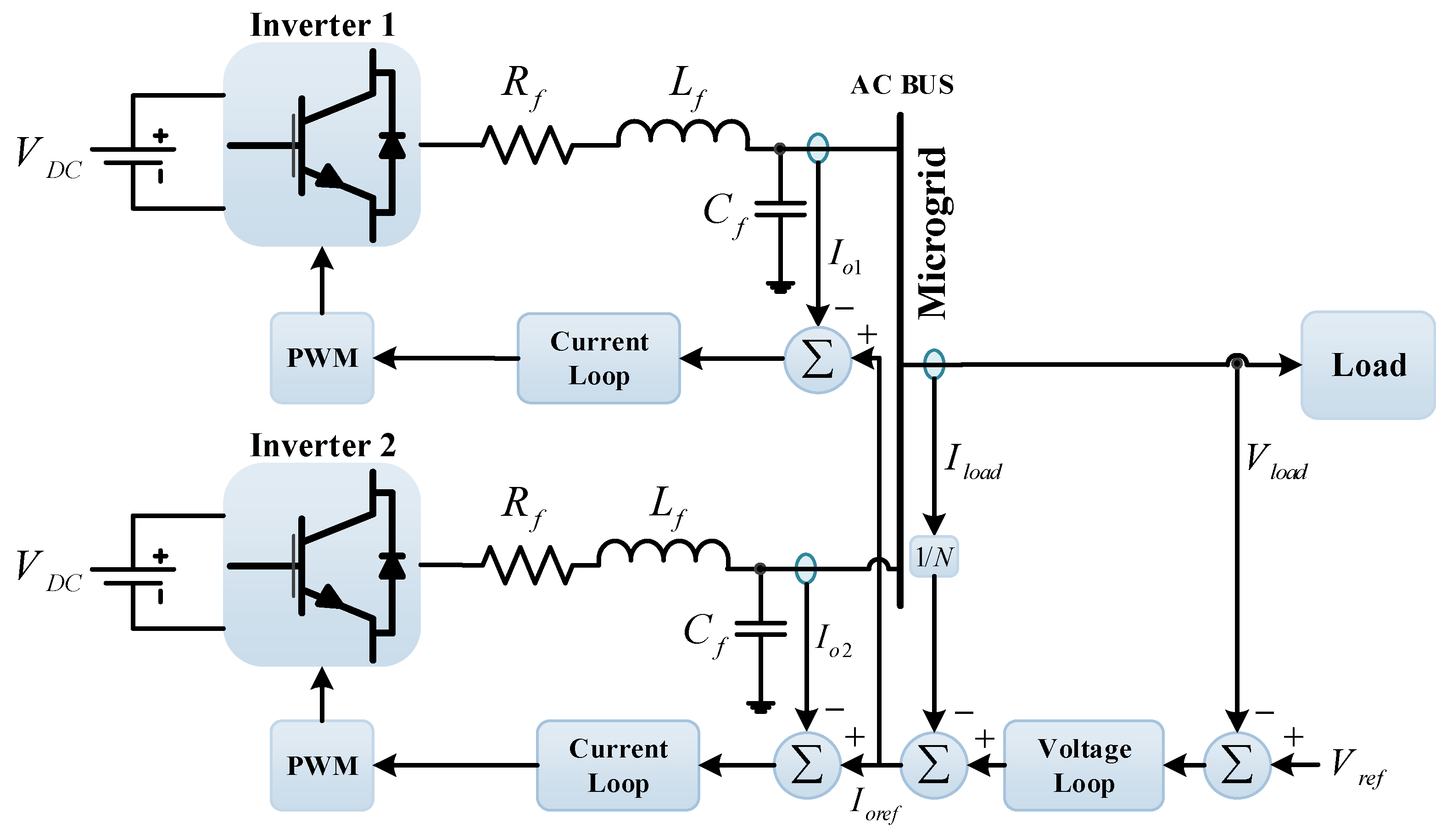
- The weighting current distribution control technique has been proposed to achieve current sharing among inverters with different power ratings. It gets a weighted output current by simply adding a simple circuit for each inverter. In this technique, each inverter has current and voltage controllers for a fast dynamic response, stability, and an improved weighted current controller for achieving current sharing among the inverters [45,58].
2.4. Summary of Communication-Based Control Strategies
3. Non-Communication-Based Control Strategies for IIDGs in Autonomous MGs
3.1. and Droop Controllers
3.2. Reverse Droop Control
3.3. Modified Droop Control
- Power angle droop control
- Virtual flux-based technique
- Voltage-based technique
- Complex droop control technique
3.3.1. Power Angle Droop Control
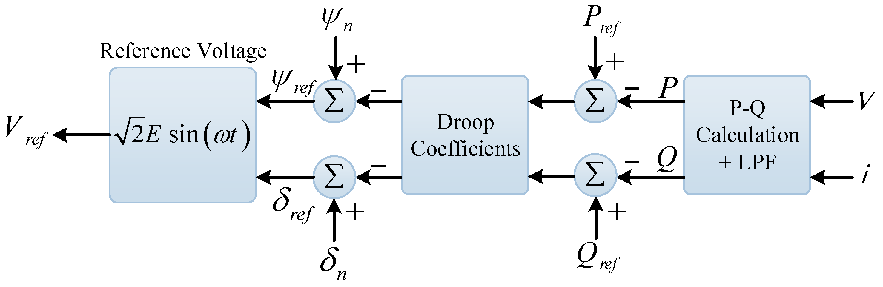
3.3.2. Virtual Flux-Based Technique
3.3.3. Current and DC Voltage-Based Droop

3.3.4. Complex Droop Control
3.4. Summary of Decentralized Droop-Based Control Techniques
4. Construction and Compensation Droop Control Method
4.1. Common Variable
4.2. Signal Injection Loop
4.3. Power Compensation Loop
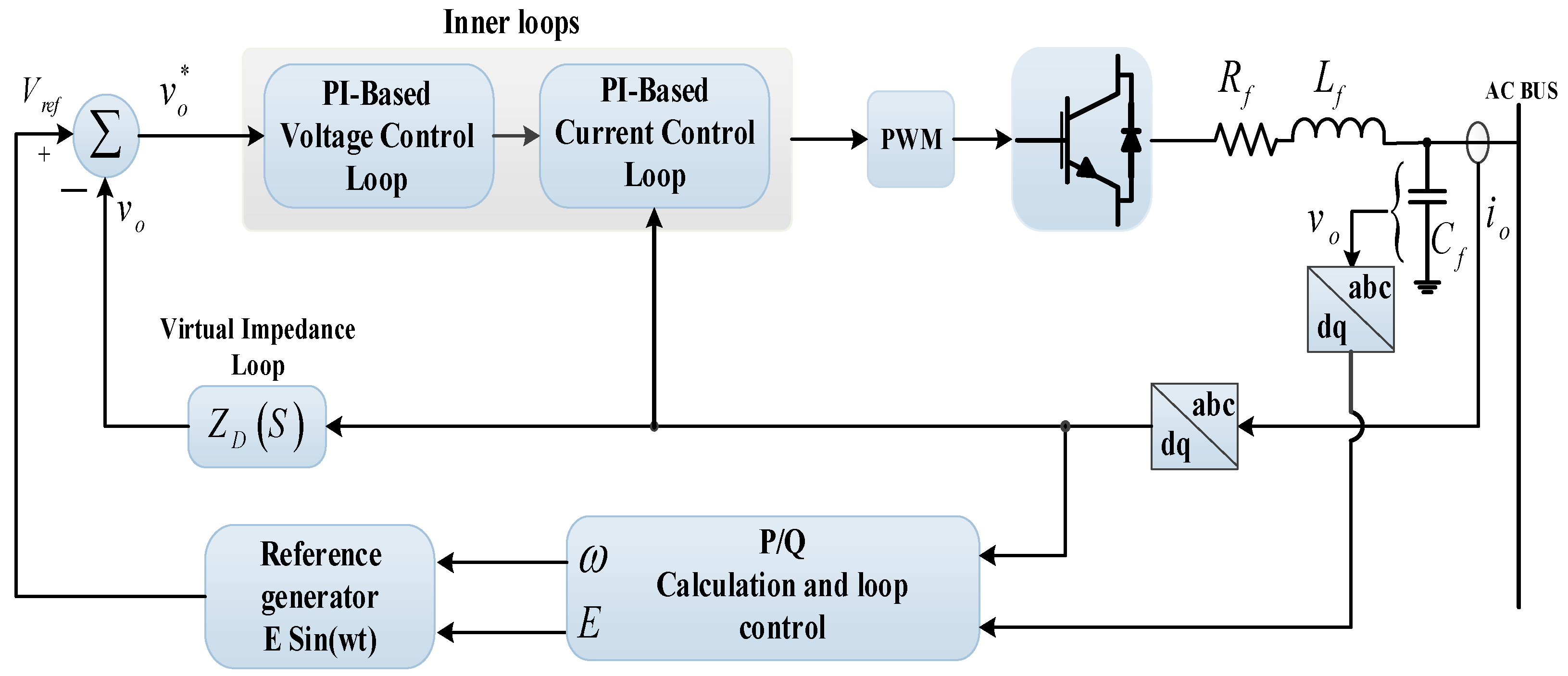
4.4. Virtual Impedance Loop
5. Advanced Control Strategies for Inverter-Based IIDGs
- Distorted/imbalanced conditions and weak grid connection: Inefficiency of classical control techniques under these conditions and eliminating/countering the uncertainties generated in the upstream grid.
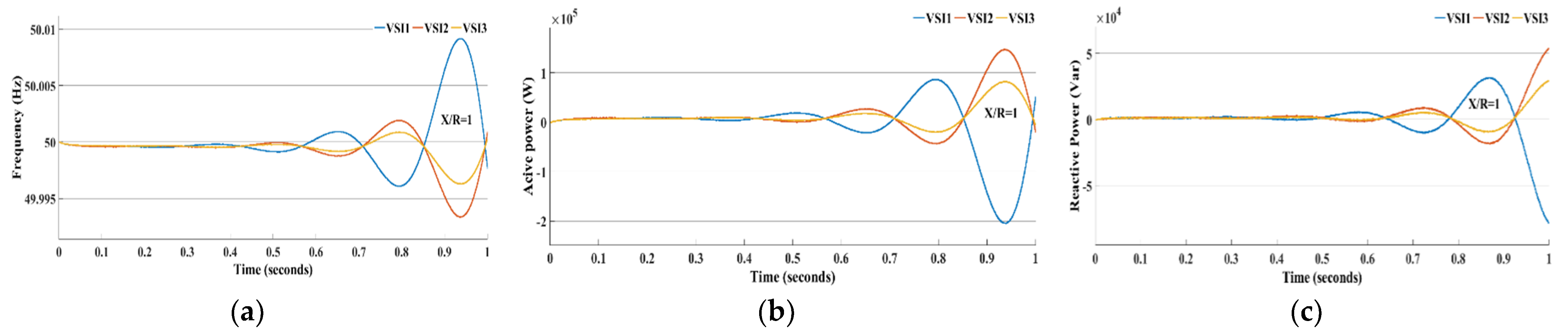
- The effect of the line impedance on power-sharing accuracy: Ineffectiveness of droop-based control methods and interaction of PI-based control loops under low X/R ratio line impedance conditions.
- Non-linear loads: In MGs, loads are topologically unknown and parametrically uncertain, and can be a source of unknown dynamics that cannot be accurately modeled by classical controllers.
- Lack of flexibility for impedance shaping of IIDGs: The GFM and GFD voltage source converters require different impedance characteristics for stable operation under different grid conditions; however, there is a lack of a sufficient degree of freedom for impedance shaping in conventional methods.
5.1. Robust Control
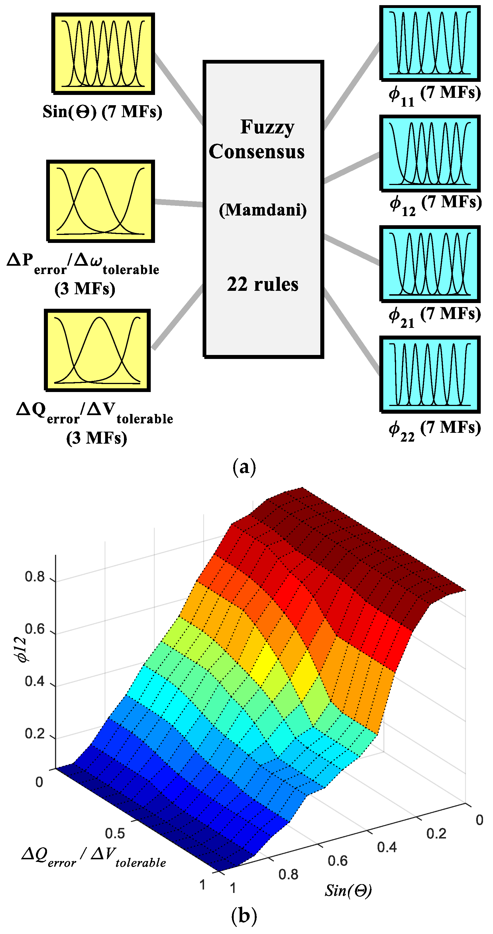
5.2. Fuzzy Control
5.3. Sliding Mode Control
5.4. Impedance Shaping
5.5. Summary Heuristic/Meta-Heuristic Algorithms
6. Future Trends in the High-Performance Inverter-Based Grids
- The contemplation of sensitivity issues with non-linear droop controller-based strategies [153] is necessary.
- Increased reliability in droop control systems based on robust controllers leads to accurate sharing of active and reactive powers among high penetration levels of IIDGs. With the development of research in this field, more solutions can be obtained [154].
- Droop methods with the aim of cost optimization, in which non-linear control methods and droop gains are variable, are open research fields, and the dynamic stability of the MG system under the influence of variable droop gains should be evaluated. Considering that the droop coefficients are adaptively changed based on the cost function using real-time optimization techniques, different computational and traceable optimization techniques are needed to increase the reliability of microgrids [152].
- Impedance shaping has been effective in stability analysis and inverter-based DER control design, including advanced control techniques. Due to the defective performance of virtual inductance loops [143,161], control methods for IIDG units are presented in [143,144]. In these methods, a degree of freedom of the optimal impedance-shaping mechanism is considered. Adaptive impedance shaping considering changes in MG structure due to plug-and-play, load changes, grid reconfiguration, and transients from islanded to grid-connected modes are among the open topics in these methods.
- Considering the different applications of battery energy storage systems (BESS) in MGs, their impact on MG economic dynamics [163,164], the different time scales of BESS application, and their joint dynamic performances in steady state, modified, and advanced droop mechanisms are needed for BESS control.
7. Conclusions
Author Contributions
Funding
Institutional Review Board Statement
Informed Consent Statement
Data Availability Statement
Conflicts of Interest
References
- Moriarty, P.; Honnery, D. Renewable Energy and Energy Reductions or Solar Geoengineering for Climate Change Mitigation? Energies 2022, 15, 7315. [Google Scholar] [CrossRef]
- Moradi, M.H.; Eskandari, M.; Hosseinian, S.M. Operational Strategy Optimization in an Optimal Sized Smart Microgrid. IEEE Trans. Smart Grid 2014, 6, 1087–1095. [Google Scholar] [CrossRef]
- Moradi, M.H.; Eskandari, M. A hybrid method for simultaneous optimization of DG capacity and operational strategy in microgrids considering uncertainty in electricity price forecasting. Renew. Energy 2014, 68, 697–714. [Google Scholar] [CrossRef]
- Mansouri, M.; Eskandari, M.; Asadi, Y.; Siano, P.; Alhelou, H.H. Pre-Perturbation Operational Strategy Scheduling in Microgrids by Two-Stage Adjustable Robust Optimization. IEEE Access 2022, 10, 74655–74670. [Google Scholar] [CrossRef]
- Anttila, S.; Döhler, J.S.; Oliveira, J.G.; Boström, C. Grid Forming Inverters: A Review of the State of the Art of Key Elements for Microgrid Operation. Energies 2022, 15, 5517. [Google Scholar] [CrossRef]
- Lin, X.; Chen, X.; Kang, Y.; Duan, S.; Chen, J. Parallel three-phase UPS inverters with a new control technique. In Proceedings of the 2002 IEEE 33rd Annual IEEE Power Electronics Specialists Conference, Proceedings (Cat. No. 02CH37289), Cairns, Australia, 23–27 June 2002. [Google Scholar] [CrossRef]
- Chandorkar, M.; Divan, D.; Adapa, R. Control of parallel connected inverters in standalone AC supply systems. IEEE Trans. Ind. Appl. 1993, 29, 136–143. [Google Scholar] [CrossRef]
- Karimi, H.; Nikkhajoei, H.; Iravani, M.R. Control of an electronically-coupled distributed resource unit subsequent to an islanding event. IEEE Trans. Power Del. 2008, 23, 493–501. [Google Scholar] [CrossRef]
- Katiraei, F.; Iravani, M.R.; Lehn, P.W. Micro-grid autonomous operation during and subsequent to islanding process. IEEE Trans. Power Del. 2005, 20, 248–257. [Google Scholar] [CrossRef]
- Sayed, K.; Almutairi, A.; Albagami, N.; Alrumayh, O.; Abo-Khalil, A.G.; Saleeb, H. A Review of DC-AC Converters for Electric Vehicle Applications. Energies 2022, 15, 1241. [Google Scholar] [CrossRef]
- Rocabert, J.; Luna, A.; Blaabjerg, F.; Rodríguez, P. Control of Power Converters in AC Microgrids. IEEE Trans. Power Electron. 2012, 27, 4734–4749. [Google Scholar] [CrossRef]
- Wang, G.; Wang, X.; Wang, F.; Han, Z. Research on Hierarchical Control Strategy of AC/DC Hybrid Microgrid Based on Power Coordination Control. Appl. Sci. 2020, 10, 7603. [Google Scholar] [CrossRef]
- Bidram, A.; Davoudi, A. Hierarchical Structure of Microgrids Control System. IEEE Trans. Smart Grid 2012, 3, 1963–1976. [Google Scholar] [CrossRef]
- Olivares, D.E.; Mehrizi-Sani, A.; Etemadi, A.H.; Cañizares, C.A.; Iravani, R.; Kazerani, M.; Hajimiragha, A.H.; Gomis-Bellmunt, O.; Saeedifard, M.; Palma-Behnke, R.; et al. Trends in microgrid control. IEEE Trans. Smart Grid 2014, 5, 1905–1919. [Google Scholar] [CrossRef]
- Yamashita, D.Y.; Vechiu, I.; Gaubert, J.-P. A review of hierarchical control for building microgrids. Renew. Sustain. Energy Rev. 2019, 118, 109523. [Google Scholar] [CrossRef]
- Vasquez, J.C.; Guerrero, J.M.; Miret, J.; Castilla, M.; de Vicuna, L.G. Hierarchical Control of Intelligent Microgrids. IEEE Ind. Electron. Mag. 2010, 4, 23–29. [Google Scholar] [CrossRef]
- Razmi, D.; Lu, T. A Literature Review of the Control Challenges of Distributed Energy Resources Based on Microgrids (MGs): Past, Present and Future. Energies 2022, 15, 4676. [Google Scholar] [CrossRef]
- Marín, L.G.; Sumner, M.; Muñoz-Carpintero, D.; Köbrich, D.; Pholboon, S.; Sáez, D.; Núñez, A. Hierarchical energy man-agement system for microgrid operation based on robust model predictive control. Energies 2019, 12, 4453. [Google Scholar] [CrossRef] [Green Version]
- Zheng, C.; Eskandari, M.; Li, M.; Sun, Z. GA−Reinforced Deep Neural Network for Net Electric Load Forecasting in Microgrids with Renewable Energy Resources for Scheduling Battery Energy Storage Systems. Algorithms 2022, 15, 338. [Google Scholar] [CrossRef]
- Moradi, M.H.; Eskandari, M.; Showkati, H. A hybrid method for simultaneous optimization of DG capacity and opera-tional strategy in microgrids utilizing renewable energy resources. Int. J. Electr. Power Energy Syst. 2014, 56, 241–258. [Google Scholar] [CrossRef]
- Chaudhary, G.; Lamb, J.J.; Burheim, O.S.; Austbø, B. Review of energy storage and energy management system control strategies in microgrids. Energies 2021, 14, 4929. [Google Scholar] [CrossRef]
- Palizban, O.; Kauhaniemi, K. Hierarchical control structure in microgrids with distributed generation: Island and grid-connected mode. Renew. Sustain. Energy Rev. 2015, 44, 797–813. [Google Scholar] [CrossRef]
- Ahmethodzic, L.; Music, M. Comprehensive review of trends in microgrid control. Renew. Energy Focus 2021, 38, 84–96. [Google Scholar] [CrossRef]
- Hu, J.; Shan, Y.; Guerrero, J.M.; Ioinovici, A.; Chan, K.W.; Rodriguez, J. Model predictive control of microgrids—An overview. Renew. Sustain. Energy Rev. 2021, 136, 110422. [Google Scholar] [CrossRef]
- Bevrani, H.; Francois, B.; Ise, T. Microgrid Dynamics and Control; John Wiley & Sons: Hoboken, NJ, USA, 2017. [Google Scholar]
- Sarkar, S.K.; Roni, H.K.; Datta, D.; Das, S.K.; Pota, H.R. Improved Design of High-Performance Controller for Voltage Control of Islanded Microgrid. IEEE Syst. J. 2018, 13, 1786–1795. [Google Scholar] [CrossRef]
- Monica, P.; Kowsalya, M. Control strategies of parallel operated inverters in renewable energy application: A review. Renew. Sustain. Energy Rev. 2016, 65, 885–901. [Google Scholar] [CrossRef]
- Han, Y.; Li, H.; Shen, P.; Coelho, E.A.A.; Guerrero, J.M. Review of Active and Reactive Power Sharing Strategies in Hierarchical Controlled Microgrids. IEEE Trans. Power Electron. 2017, 32, 2427–2451. [Google Scholar] [CrossRef] [Green Version]
- Han, H.; Hou, X.; Yang, J.; Wu, J.; Su, M.; Guerrero, J.M. Review of Power Sharing Control Strategies for Islanding Operation of AC Microgrids. IEEE Trans. Smart Grid 2016, 7, 200–215. [Google Scholar] [CrossRef] [Green Version]
- Das, S.; Nutkani, I.U.; Teixeira, C.A. Decentralized Master–Slave Control for Series-Cascaded Islanded AC Mi-crogrid. IEEE Trans. Ind. Electron. 2021, 69, 5942–5951. [Google Scholar] [CrossRef]
- Sun, X.; Wong, L.-K.; Lee, Y.-S.; Xu, D. Design and analysis of an optimal controller for parallel multi-inverter systems. IEEE Trans. Circuits Syst. II Express Briefs 2006, 53, 56–61. [Google Scholar] [CrossRef]
- Guerrero, J.M.; Chandorkar, M.; Lee, T.-L.; Loh, P.C. Advanced Control Architectures for Intelligent Microgrids—Part I: Decentralized and Hierarchical Control. IEEE Trans. Ind. Electron. 2013, 60, 1254–1262. [Google Scholar] [CrossRef] [Green Version]
- Asadi, Y.; Eskandari, M.; Mansouri, M.; Chaharmahali, S.; Moradi, M.H.; Tahriri, M.S. Adaptive Neural Network for a Stabilizing Shunt Active Power Filter in Distorted Weak Grids. Appl. Sci. 2022, 12, 8060. [Google Scholar] [CrossRef]
- Blaabjerg, F.; Teodorescu, R.; Liserre, M.; Timbus, A.V. Overview of Control and Grid Synchronization for Distributed Power Generation Systems. IEEE Trans. Ind. Electron. 2006, 53, 1398–1409. [Google Scholar] [CrossRef] [Green Version]
- Vandoorn, T.L.; De Kooning, J.D.M.; Meersman, B.; Vandevelde, L. Review of primary control strategies for islanded microgrids with power-electronic interfaces. Renew. Sustain. Energy Rev. 2013, 19, 613–628. [Google Scholar] [CrossRef]
- Kreishan, M.; Zobaa, A. Optimal Allocation and Operation of Droop-Controlled Islanded Microgrids: A Review. Energies 2021, 14, 4653. [Google Scholar] [CrossRef]
- Guerrero, J.M.; Hang, L.; Uceda, J. Control of Distributed Uninterruptible Power Supply Systems. IEEE Trans. Ind. Electron. 2008, 55, 2845–2859. [Google Scholar] [CrossRef] [Green Version]
- Li, C.; Savaghebi, M.; Guerrero, J.M.; Coelho, E.A.A.; Vasquez, J.C. Operation Cost Minimization of Droop-Controlled AC Microgrids Using Multiagent-Based Distributed Control. Energies 2016, 9, 717. [Google Scholar] [CrossRef] [Green Version]
- Kawabata, T.; Sashida, N.; Yamamoto, Y.; Ogasawara, K.; Yamasaki, Y. Parallel processing inverter system. IEEE Trans. Power Electron. 1991, 6, 442–450. [Google Scholar] [CrossRef]
- Thunes, J.; Kerkman, R.; Schlegel, D.; Rowan, T. Current regulator instabilities on parallel voltage-source inverters. IEEE Trans. Ind. Appl. 1999, 35, 70–77. [Google Scholar] [CrossRef]
- Chen, J.-F.; Chu, C.-L. Combination voltage-controlled and current-controlled PWM inverters for UPS parallel operation. IEEE Trans. Power Electron. 1995, 10, 547–558. [Google Scholar] [CrossRef]
- Pogaku, N.; Prodanovic, M.; Green, T.C. Modeling, analysis and testing of autonomous operation of an invert-er-based microgrid. IEEE Trans. Power Electron. 2007, 22, 613–625. [Google Scholar] [CrossRef] [Green Version]
- Holtz, J.; Werner, K.-H. Multi-inverter UPS system with redundant load sharing control. IEEE Trans. Ind. Electron. 1990, 37, 506–513. [Google Scholar] [CrossRef]
- Wu, T.-F.; Chen, Y.-K.; Huang, Y.-H. 3C strategy for inverters in parallel operation achieving an equal current distribution. IEEE Trans. Ind. Electron. 2000, 47, 273–281. [Google Scholar] [CrossRef]
- Liang, H.; Zhuang, W. Stochastic Modeling and Optimization in a Microgrid: A Survey. Energies 2014, 7, 2027–2050. [Google Scholar] [CrossRef] [Green Version]
- Borrega, M.; Marroyo, L.; González, R.; Balda, J.; Agorreta, J.L. Modeling and Control of a Master–Slave PV Inverter With N-Paralleled Inverters and Three-Phase Three-Limb Inductors. IEEE Trans. Power Electron. 2012, 28, 2842–2855. [Google Scholar] [CrossRef]
- Abdelaziz, M.M.A.; Shaaban, M.F.; Farag, H.E.; El-Saadany, E.F. A Multistage Centralized Control Scheme for Islanded Microgrids with PEVs. IEEE Trans. Sustain. Energy 2014, 5, 927–937. [Google Scholar] [CrossRef]
- Alsafran, A.S.; Daniels, M.W. Consensus Control for Reactive Power Sharing Using an Adaptive Virtual Impedance Approach. Energies 2020, 13, 2026. [Google Scholar] [CrossRef]
- Rajesh, K.S.; Dash, S.S.; Rajagopal, R.; Sridhar, R. A review on control of ac microgrid. Renew. Sustain. Energy Rev. 2017, 71, 814–819. [Google Scholar] [CrossRef]
- Espín-Sarzosa, D.; Palma-Behnke, R.; Núñez-Mata, O. Energy Management Systems for Microgrids: Main Existing Trends in Centralized Control Architectures. Energies 2020, 13, 547. [Google Scholar] [CrossRef] [Green Version]
- Yang, Y.; Qin, Y.; Tan, S.-C.; Hui, S.Y.R. Reducing Distribution Power Loss of Islanded AC Microgrids Using Distributed Electric Springs with Predictive Control. IEEE Trans. Ind. Electron. 2020, 67, 9001–9011. [Google Scholar] [CrossRef]
- Jeong, B.-C. Modified Master–Slave Controller for Stable Power Supply of Energy Storage Based Microgrid. Energies 2022, 15, 4245. [Google Scholar] [CrossRef]
- Zhang, C.; Chen, G.; Guo, Z.; Wu, W. An Alternating-master-salve Parallel Control Research for Single Phase Paralleled Inverters Based on CAN Bus. In Proceedings of the 2006 CES/IEEE 5th International Power Electronics and Motion Control Conference, Shanghai, China, 14–16 August 2006. [Google Scholar]
- Tan, J.; Lin, H.; Zhang, J.; Ying, J. A novel load sharing control technique for paralleled inverters. In Proceedings of the IEEE 34th Annual Conference on Power Electronics Specialist, Acapulco, Mexico, 15–19 June 2003. [Google Scholar] [CrossRef]
- Ogasawara, S.; Takagaki, J.; Akagi, H.; Nabae, A. A novel control scheme of a parallel current-controlled PWM inverter. IEEE Trans. Ind. Appl. 1992, 28, 1023–1030. [Google Scholar] [CrossRef]
- Chen, L.; Xiao, L.; Yan, Y. A novel parallel inverter system based on coupled inductors. In Proceedings of the 25th International Telecommunications Energy Conference, Yokohama, Japan, 23 October 2003; pp. 46–50. [Google Scholar]
- Chen, Y.; Smedley, K.M. One-Cycle-Controlled Three-Phase Grid-Connected Inverters and Their Parallel Operation. IEEE Trans. Ind. Appl. 2008, 44, 663–671. [Google Scholar] [CrossRef]
- Wu, T.-F.; Wu, Y.-E.; Hsieh, H.-M.; Chen, Y.-K. Current Weighting Distribution Control Strategy for Multi-Inverter Systems to Achieve Current Sharing. IEEE Trans. Power Electron. 2007, 22, 160–168. [Google Scholar] [CrossRef]
- Sikder, S.H.; Rahman, M.; Sarkar, S.K.; Das, S.K. Fractional Order Robust PID Controller Design for Voltage Control of Islanded Microgrid. In Proceedings of the 2018 4th International Conference on Electrical Engineering and Information & Communication Technology (iCEEiCT), Dhaka, Bangladesh, 13–15 September 2018; pp. 234–239. [Google Scholar] [CrossRef]
- Li, Y.W.; Kao, C.-N. An Accurate Power Control Strategy for Power-Electronics-Interfaced Distributed Generation Units Operating in a Low-Voltage Multibus Microgrid. IEEE Trans. Power Electron. 2009, 24, 2977–2988. [Google Scholar] [CrossRef]
- Natesan, C.; Ajithan, S.; Mani, S.; Kandhasamy, P. Applicability of Droop Regulation Technique in Microgrid—A Survey. Eng. J. 2014, 18, 23–36. [Google Scholar] [CrossRef] [Green Version]
- Zamora, R.; Srivastava, A.K. Controls for microgrids with storage: Review, challenges, and research needs. Renew. Sustain. Energy Rev. 2010, 14, 2009–2018. [Google Scholar] [CrossRef]
- Guerrero, J.M.; Vasquez, J.C.; Matas, J.; Castilla, M.; de Vicuna, L.G. Control Strategy for Flexible Microgrid Based on Parallel Line-Interactive UPS Systems. IEEE Trans. Ind. Electron. 2008, 56, 726–736. [Google Scholar] [CrossRef]
- Hou, X.; Sun, Y.; Yuan, W.; Han, H.; Zhong, C.; Guerrero, J.M. Conventional P-ω/QV droop control in highly resistive line of low-voltage converter-based AC microgrid. Energies 2016, 9, 943. [Google Scholar] [CrossRef] [Green Version]
- Llaria, A.; Curea, O.; Jiménez, J.; Camblong, H. Survey on microgrids: Unplanned islanding and related inverter control techniques. Renew. Energy 2011, 36, 2052–2061. [Google Scholar] [CrossRef]
- Coelho, E.; Cortizo, P.; Garcia, P. Small-signal stability for parallel-connected inverters in stand-alone AC supply systems. IEEE Trans. Ind. Appl. 2002, 38, 533–542. [Google Scholar] [CrossRef]
- Eskandari, M.; Li, L. A novel small signal model of multi-bus microgrids for modeling interaction of droop controllers through the power network. In Proceedings of the 2017 20th International Conference on Electrical Machines and Systems (ICEMS), Sydney, Australia, 11–14 August 2017; pp. 1–6. [Google Scholar]
- Wu, D.; Tang, F.; Vasquez, J.C.; Guerrero, J.M. Control and analysis of droop and reverse droop con-trollers for distributed generations. In Proceedings of the 2014 IEEE 11th International Multi-Conference on Systems, Signals & Devices (SSD14), Barcelona, Spain, 11–14 February 2014; pp. 1–5. [Google Scholar]
- Guerrero, J.M.; Matas, J.; De Vicuñna, L.G.; Castilla, M.; Miret, J. Wireless-Control Strategy for Parallel Operation of Distributed-Generation Inverters. IEEE Trans. Ind. Electron. 2006, 53, 1461–1470. [Google Scholar] [CrossRef]
- Guerrero, J.M.; Vasquez, J.C.; Teodorescu, R. Hierarchical control of droop-controlled DC and AC microgrids—A general approach towards standardization. IEEE Trans. Ind. Electron. 2009, 58, 4305–4310. [Google Scholar] [CrossRef] [Green Version]
- Skea, J.; Anderson, D.; Green, T.; Gross, R.; Heptonstall, P.; Leach, M. Intermittent renewable generation and the cost of maintaining power system reliability. IET Gener. Transm. Distrib. 2008, 2, 82–89. [Google Scholar] [CrossRef]
- Majumder, R.; Chaudhuri, B.; Ghosh, A.; Majumder, R.; Ledwich, G.; Zare, F. Improvement of Stability and Load Sharing in an Autonomous Microgrid Using Supplementary Droop Control Loop. IEEE Trans. Power Syst. 2010, 25, 796–808. [Google Scholar] [CrossRef] [Green Version]
- Solanki, A.; Nasiri, A.; Bhavaraju, V.; Familiant, Y.L.; Fu, Q. A New Framework for Microgrid Management: Virtual Droop Control. IEEE Trans. Smart Grid 2015, 7, 554–566. [Google Scholar] [CrossRef]
- Hu, J.; Zhu, J.; Dorrell, D.G.; Guerrero, J.M. Virtual Flux Droop Method—A New Control Strategy of Inverters in Microgrids. IEEE Trans. Power Electron. 2013, 29, 4704–4711. [Google Scholar] [CrossRef] [Green Version]
- Golsorkhi, M.S.; Lu, D.D.C. A Control Method for Inverter-Based Islanded Microgrids Based on V-I Droop Characteristics. IEEE Trans. Power Deliv. 2014, 30, 1196–1204. [Google Scholar] [CrossRef]
- Vandoorn, T.L.; Meersman, B.; Degroote, L.; Renders, B.; Vandevelde, L. A Control Strategy for Islanded Microgrids With DC-Link Voltage Control. IEEE Trans. Power Deliv. 2011, 26, 703–713. [Google Scholar] [CrossRef]
- Heidari, S.; Hatami, A.; Eskandari, M. An intelligent capacity management system for interface converter in AC-DC hybrid microgrids. Appl. Energy 2022, 316, 119112. [Google Scholar] [CrossRef]
- Auy-Yeung, J.; Vanalme, G.M.A.; Myrzik, J.M.A.; Karaliolios, P.; Bongaerts, M.; Bozelie, J.; Kling, W.L. Development of a Voltage and Frequency Control Strategy for an Autonomous LV Network with Distributed Generators. In Proceedings of the 2009 44th International Universities Power Engineering Conference, Glasgow, UK, 1–4 September 2009. [Google Scholar]
- Guerrero, J.M.; Berbel, N.; Matas, J.; de Vicuna, L.G.; Miret, J. Decentralized Control for Parallel Operation of Distributed Generation Inverters Using Resistive Output Impedance. IEEE Trans. Ind. Electron. 2017, 54, 994–1004. [Google Scholar] [CrossRef]
- Sun, Y.; Zhong, C.; Hou, X.; Yang, J.; Han, H.; Guerrero, J.M. Distributed cooperative synchronization strategy for multi-bus microgrids. Int. J. Electr. Power Energy Syst. 2017, 86, 18–28. [Google Scholar] [CrossRef] [Green Version]
- Yao, W.; Chen, M.; Matas, J.; Guerrero, J.M.; Qian, Z.-M. Design and Analysis of the Droop Control Method for Parallel Inverters Considering the Impact of the Complex Impedance on the Power Sharing. IEEE Trans. Ind. Electron. 2010, 58, 576–588. [Google Scholar] [CrossRef]
- Wang, J.; Song, Y.; Monti, A.; Jing, W. Design of a high performance deadbeat-type current controller for LCL-filtered grid-parallel inverters. In Proceedings of the 2015 IEEE 6th International Symposium on Power Electronics for Distributed Generation Systems (PEDG), Aachen, Germany, 22–25 June 2015; pp. 1–8. [Google Scholar] [CrossRef]
- Guan, Y.; Wu, W.; Guo, X.; Gu, H. An improved droop controller for grid-connected voltage source inverter in microgrid. In Proceedings of the 2nd International Symposium on Power Electronics for Distributed Generation Systems, Hefei, China, 16–18 June 2010; 823–828. [Google Scholar] [CrossRef]
- Mohamed, Y.A.-R.I.; El-Saadany, E.F. Adaptive Decentralized Droop Controller to Preserve Power Sharing Stability of Paralleled Inverters in Distributed Generation Microgrids. IEEE Trans. Power Electron. 2008, 23, 2806–2816. [Google Scholar] [CrossRef]
- Guerrero, J.M.; Vasquez, J.C.; Matas, J.; de Vicuna, L.G.; Castilla, M. Hierarchical Control of Droop-Controlled AC and DC Microgrids—A General Approach Toward Standardization. IEEE Trans. Ind. Electron. 2011, 58, 158–172. [Google Scholar] [CrossRef]
- Guerrero, J.; Matas, J.; de Vicuna, L.; Berbel, N.; Sosa, J. Wireless-control strategy for parallel operation of distributed generation inverters. IEEE Trans. Ind. Electron. 2005, 2, 845–850. [Google Scholar] [CrossRef]
- Hatziargyriou, N.; Jenkins, N.; Strbac, G.; Lopes, J.P.; Ruela, J.; Engler, A.; Oyarzabal, J.; Kariniotakis, G.; Amorim, A. MICROGRIDS—Large Scale Integration of Micro-Generation to Low Voltage Grids; University of Athens: Athens, Greece, 2006; pp. 1–24. [Google Scholar] [CrossRef]
- Lee, C.-T.; Chuang, C.-C.; Chu, C.-C.; Cheng, P.-T. Control strategies for distributed energy resources interface converters in the low voltage Microgrid. In Proceedings of the 2009 IEEE Energy Conversion Congress and Exposition, San Jose, CA, USA, 20–24 September 2009; pp. 2022–2029. [Google Scholar] [CrossRef]
- Guerrero, J.M.; GarciadeVicuna, L.; Matas, J.; Castilla, M.; Miret, J. Output Impedance Design of Parallel-Connected {UPS} Inverters with Wireless Load-Sharing Control. IEEE Trans. Ind. Electron. 2005, 52, 1126–1135. [Google Scholar] [CrossRef]
- Rokrok, E.; Golshan, M. Adaptive voltage droop scheme for voltage source converters in an islanded multibus microgrid. IET Gener. Transm. Distrib. 2010, 4, 562–578. [Google Scholar] [CrossRef] [Green Version]
- Hassanzahraee, M.; Bakhshai, A. Adaptive transient power control strategy for parallel-connected inverters in an islanded microgrid. In Proceedings of the IECON 2012-38th Annual Conference on IEEE Industrial Electronics Society, Montreal, QC, Canada, 25–28 October 2012; pp. 5926–5931. [Google Scholar] [CrossRef]
- Ahn, S.-J.; Park, J.-W.; Chung, I.-Y.; Moon, S.-I.; Kang, S.-H.; Nam, S.-R. Power-Sharing Method of Multiple Distributed Generators Considering Control Modes and Configurations of a Microgrid. IEEE Trans. Power Deliv. 2010, 25, 2007–2016. [Google Scholar] [CrossRef]
- Yu, K.; Ai, Q.; Wang, S.; Ni, J.; Lv, T. Analysis and Optimization of Droop Controller for Microgrid System Based on Small-Signal Dynamic Model. IEEE Trans. Smart Grid 2015, 7, 1–11. [Google Scholar] [CrossRef]
- Díaz, G.; González-morán, C.; Gómez-aleixandre, J.; Diez, A. Scheduling of Droop Coefficients for Frequency and Voltage Regu-lation in Isolated Microgrids. IEEE Trans. Power Syst. 2010, 25, 489–496. [Google Scholar] [CrossRef]
- Maulik, A.; Das, D. Optimal Operation of Droop-Controlled Islanded Microgrids. IEEE Trans. Sustain. Energy 2017, 9, 1337–1348. [Google Scholar] [CrossRef]
- Sahyoun, S.; Djouadi, S.; Shankar, M. Optimal Control of Droop Controlled Inverters in Islanded Microgrids. IFAC-PapersOnLine 2015, 48, 363–368. [Google Scholar] [CrossRef]
- Tuladhar, A.; Jin, H.; Unger, T.; Mauch, K. Parallel operation of single phase inverter modules with no control interconnections. In Proceedings of the APEC 97-Applied Power Electronics Conference, Atlanta, GA, USA, 27 February 1997. [Google Scholar] [CrossRef]
- Perreault, D.J.; Selders, R.L.; Kassakian, J.G. Frequency-based current-sharing techniques for paralleled power converters. IEEE Trans. Power Electron. 1998, 13, 626–634. [Google Scholar] [CrossRef]
- He, J.; Li, Y.W.; Guerrero, J.M.; Blaabjerg, F.; Vasquez, J.C. An Islanding Microgrid Power Sharing Approach Using Enhanced Virtual Impedance Control Scheme. IEEE Trans. Power Electron. 2013, 28, 5272–5282. [Google Scholar] [CrossRef]
- Shafiee, Q.; Vasquez, J.C.; Guerrero, J.M. Distributed secondary control for islanded MicroGrids—A networked control systems approach. In Proceedings of the IECON 2012—38th Annual Conference on IEEE Industrial Electronics Society, Montreal, QC, Canada, 25–28 October 2012; pp. 5637–5642. [Google Scholar]
- Li, Y.; Fan, L. Stability Analysis of Two Parallel Converters with Voltage-Current Droop Control. IEEE Trans. Power Deliv. 2017, 32. [Google Scholar] [CrossRef]
- Vasquez, J.C.; Guerrero, J.M.; Savaghebi, M.; Eloy-Garcia, J.; Teodorescu, R. Modeling, Analysis, and Design of Stationary-Reference-Frame Droop-Controlled Parallel Three-Phase Voltage Source Inverters. IEEE Trans. Ind. Electron. 2012, 60, 1271–1280. [Google Scholar] [CrossRef] [Green Version]
- Neves, R.V.A.; Machado, R.Q.; Oliveira, V.A.; Wang, X.; Blaabjerg, F. Multitask Fuzzy Secondary Controller for AC Microgrid Operating in Stand-Alone and Grid-Tied Mode. IEEE Trans. Smart Grid 2018, 10, 5640–5649. [Google Scholar] [CrossRef]
- Eskandari, M.; Li, L.; Moradi, M.H. Decentralized Optimal Servo Control System for Implementing Instantaneous Reactive Power Sharing in Microgrids. IEEE Trans. Sustain. Energy 2017, 9, 525–537. [Google Scholar] [CrossRef]
- Sao, C.K.; Lehn, P.W. Control and Power Management of Converter Fed Microgrids. IEEE Trans. Power Syst. 2008, 23, 1088–1098. [Google Scholar] [CrossRef]
- Eskandari, M.; Li, L.; Moradi, M.H.; Siano, P.; Blaabjerg, F. Simultaneous reactive power sharing and voltage regulation in an autonomous networked microgrid. IET Gener. Transm. Distrib. 2020, 14, 1366–1377. [Google Scholar] [CrossRef] [Green Version]
- He, J.; Li, Y.W. An Enhanced Microgrid Load Demand Sharing Strategy. IEEE Trans. Power Electron. 2012, 27, 3984–3995. [Google Scholar] [CrossRef]
- He, J.; Li, Y.W. An accurate reactive power sharing control strategy for DG units in a microgrid. In Proceedings of the 8th International Conference on Power Electronics—ECCE Asia, Jeju, Korea, 30 May–3 June 2011; pp. 551–556. [Google Scholar]
- Vasquez, J.C.; Guerrero, J.M.; Member, S.; Luna, A.; Rodríguez, P.; Teodorescu, R. Adaptive Droop Control Applied to Volt-age-Source Inverters Operating in Grid-Connected and Islanded Modes. IEEE Trans. Ind. Electron. 2009, 56, 4088–4096. [Google Scholar] [CrossRef]
- Buraimoh, E.; Aluko, A.O.; Oni, O.E.; Davidson, I.E. Decentralized Virtual Impedance- Conventional Droop Control for Power Sharing for Inverter-Based Distributed Energy Resources of a Microgrid. Energies 2022, 15, 4439. [Google Scholar] [CrossRef]
- Axelrod, B.; Berkovich, Y.; Ioinovici, A. Using Enhanced Virtual Impedance Control Scheme. In Proceedings of the 2003 International Symposium on Circuits and Systems, ISCAS 2003, Bangkok, Thailand, 25–28 May 2003; Volume 3, pp. 5272–5282. [Google Scholar]
- Guerrero, J.M.; Loh, P.C.; Lee, T.-L.; Chandorkar, M. Advanced Control Architectures for Intelligent Microgrids—Part II: Power Quality, Energy Storage, and AC/DC Microgrids. IEEE Trans. Ind. Electron. 2012, 60, 1263–1270. [Google Scholar] [CrossRef] [Green Version]
- Eskandari, M. Intelligent and Robust Control Strategy for Improving Microgrids Operation and Stability. Ph.D. Thesis, OPUS, Open Publications of UTS Scholars, Ultimo, Australia, 2020. [Google Scholar]
- He, J.; Li, Y.W. Analysis, Design, and Implementation of Virtual Impedance for Power Electronics Interfaced Distributed Generation. IEEE Trans. Ind. Appl. 2011, 47, 2525–2538. [Google Scholar] [CrossRef]
- Lyu, Z.; Wei, Q.; Zhang, Y.; Zhao, J.; Manla, E. Adaptive Virtual Impedance Droop Control Based on Consensus Control of Reactive Current. Energies 2018, 11, 1801. [Google Scholar] [CrossRef] [Green Version]
- Li, Y.; Li, Y.W. Virtual frequency-voltage frame control of inverter based low voltage microgrid. In Proceedings of the 2009 IEEE Electrical Power & Energy Conference (EPEC), Montreal, QC, Canada, 22–23 October 2009; pp. 1–6. [Google Scholar] [CrossRef]
- Li, Y.; Li, Y.W. Power Management of Inverter Interfaced Autonomous Microgrid Based on Virtual Frequency-Voltage Frame. IEEE Trans. Smart Grid 2011, 2, 30–40. [Google Scholar] [CrossRef]
- Guerrero, J.; De Vicuna, L.G.; Matas, J.; Miret, J. Steady-state invariant-frequency control of parallel redundant uninterruptible power supplies. In Proceedings of the IEEE 2002 28th Annual Conference of the Industrial Electronics Society, Sevilla, Spain, 5–8 November 2002. [Google Scholar] [CrossRef]
- Panjaitan, S.D.; Kurnianto, R.; Sanjaya, B.W.; Turner, M.C. Control of Parallel Inverters for High Power Quality and Sharing Accuracy in Single-Phase AC Microgrids. In Proceedings of the 2018 UKACC 12th International Conference on Control (CONTROL), Sheffield, UK, 5–7 September 2018; pp. 50–55. [Google Scholar] [CrossRef]
- Mohammadi, F.; Mohammadi-Ivatloo, B.; Gharehpetian, G.B.; Ali, M.H.; Wei, W.; Erdinc, O.; Shirkhani, M. Robust Control Strategies for Microgrids: A Review. IEEE Syst. J. 2021, 16, 2401–2412. [Google Scholar] [CrossRef]
- Sedhom, B.E.; El-Saadawi, M.M.; Hatata, A.Y.; Elhosseini, M.A.; Abd-Raboh, E.E. Robust Control Technique in an Autonomous Microgrid: A Multi-stage H∞ Controller Based on Harmony Search Algorithm. Iran. J. Sci. Technol. Trans. Electr. Eng. 2019, 44, 377–402. [Google Scholar] [CrossRef]
- Ge, P.; Dou, X.; Quan, X.; Hu, Q.; Sheng, W.; Wu, Z.; Gu, W. Extended-State-Observer-Based Distributed Robust Secondary Voltage and Frequency Control for an Autonomous Microgrid. IEEE Trans. Sustain. Energy 2018, 11, 195–205. [Google Scholar] [CrossRef]
- Imran, R.M.; Wang, S.; Flaih, F.M.F. DQ-Voltage Droop Control and Robust Secondary Restoration with Eligibility to Operate During Communication Failure in Autonomous Microgrid. IEEE Access 2018, 7, 6353–6361. [Google Scholar] [CrossRef]
- Eskandari, M.; Savkin, A.V. A Critical Aspect of Dynamic Stability in Autonomous Microgrids: Interaction of Droop Controllers Through the Power Network. IEEE Trans. Ind. Inform. 2021, 18, 3159–3170. [Google Scholar] [CrossRef]
- Hossen, T.; Sadeque, F. On Stability, Ancillary Services, Operation, and Security of Smart Inverters. arXiv 2021, arXiv:2112.06787. [Google Scholar]
- Tuckey, A.; Round, S. Grid-Forming Inverters for Grid-Connected Microgrids: Developing “good citizens” to ensure the continued flow of stable, reliable power. IEEE Electrif. Mag. 2022, 10, 39–51. [Google Scholar] [CrossRef]
- Eskandari, M.; Savkin, A.V. Robust PLL Synchronization Unit for Grid-Feeding Converters in Micro/Weak Grids. IEEE Trans. Ind. Inform. 2022. [Google Scholar] [CrossRef]
- Karimi, A.; Khayat, Y.; Naderi, M.; Dragičević, T.; Mirzaei, R.; Blaabjerg, F.; Bevrani, H. Inertia response improve-ment in AC microgrids: A fuzzy-based virtual synchronous generator control. IEEE Trans. Power Electron. 2019, 35, 4321–4331. [Google Scholar] [CrossRef]
- Hosseinalizadeh, T.; Kebriaei, H.; Salmasi, F.R. Decentralised robust T-S fuzzy controller for a parallel islanded AC microgrid. IET Gener. Transm. Distrib. 2019, 13, 1589–1598. [Google Scholar] [CrossRef]
- Zhang, S.; Mishra, Y.; Shahidehpour, M. Fuzzy-Logic Based Frequency Controller for Wind Farms Augmented with Energy Storage Systems. IEEE Trans. Power Syst. 2016, 31, 1595–1603. [Google Scholar] [CrossRef]
- Andalib-Bin-Karim, C.; Liang, X.; Zhang, H. Fuzzy-Secondary-Controller-Based Virtual Synchronous Generator Control Scheme for Interfacing Inverters of Renewable Distributed Generation in Microgrids. IEEE Trans. Ind. Appl. 2017, 54, 1047–1061. [Google Scholar] [CrossRef]
- Moradi, M.H.; Eskandari, M.; Siano, P. Safe transition from connection mode to islanding mode in Microgrids. In Proceedings of the 2016 24th Iranian Conference on Electrical Engineering (ICEE), Shiraz, Iran, 10–12 May 2016; pp. 1902–1907. [Google Scholar] [CrossRef]
- Han, H.; Liu, Y.; Sun, Y.; Su, M.; Guerrero, J.M. An Improved Droop Control Strategy for Reactive Power Sharing in Islanded Microgrid. IEEE Trans. Power Electron. 2014, 30, 3133–3141. [Google Scholar] [CrossRef] [Green Version]
- Eskandari, M.; Li, L.; Moradi, M.H. Improving power sharing in islanded networked microgrids using fuzzy-based consensus control. Sustain. Energy Grids Netw. 2018, 16, 259–269. [Google Scholar] [CrossRef]
- Mohamed, Y.A.R.I.; El-Saadany, E.F. Robust high bandwidth discrete-time predictive current control with pre-dictive internal model—A unified approach for voltage-source PWM converters. IEEE Trans. Power Electron. 2008, 23, 126–136. [Google Scholar] [CrossRef]
- Delghavi, M.B.; Yazdani, A. Islanded-mode control of electronically coupled distributed-resource units under un-balanced and nonlinear load conditions. IEEE Trans. Power Deliv. 2010, 26, 661–673. [Google Scholar] [CrossRef]
- Cucuzzella, M.; Incremona, G.P.; Ferrara, A. Decentralized Sliding Mode Control of Islanded AC Microgrids With Arbitrary Topology. IEEE Trans. Ind. Electron. 2017, 64, 6706–6713. [Google Scholar] [CrossRef] [Green Version]
- Delghavi, M.B.; Shoja-Majidabad, S.; Yazdani, A. Fractional-Order Sliding-Mode Control of Islanded Distributed Energy Resource Systems. IEEE Trans. Sustain. Energy 2016, 7, 1482–1491. [Google Scholar] [CrossRef]
- Baghaee, H.R.; Mirsalim, M.; Gharehpetian, G.B.; Talebi, H.A. A Decentralized Power Management and Sliding Mode Control Strategy for Hybrid AC/DC Microgrids including Renewable Energy Resources. IEEE Trans. Ind. Inform. 2017, 1. [Google Scholar] [CrossRef]
- Baghaee, H.R.; Mirsalim, M.; Gharehpetian, G.B.; Talebi, H.A. Decentralized Sliding Mode Control of WG/PV/FC Microgrids Under Unbalanced and Nonlinear Load Conditions for On- and Off-Grid Modes. IEEE Syst. J. 2017, 12, 3108–3119. [Google Scholar] [CrossRef]
- Eskandari, M.; Savkin, A.V. On the Impact of Fault Ride-Through on Transient Stability of Autonomous Microgrids: Nonlinear Analysis and Solution. IEEE Trans. Smart Grid 2020, 12, 999–1010. [Google Scholar] [CrossRef]
- Harnefors, L.; Wang, X.; Yepes, A.G.; Blaabjerg, F. Passivity-Based Stability Assessment of Grid-Connected VSCs—An Overview. IEEE J. Emerg. Sel. Top. Power Electron. 2015, 4, 116–125. [Google Scholar] [CrossRef] [Green Version]
- Eskandari, M.; Li, L.; Moradi, M.H.; Siano, P.; Blaabjerg, F. Optimal Voltage Regulator for Inverter Interfaced Distributed Generation Units Part I: Control System. IEEE Trans. Sustain. Energy 2020, 11, 2813–2824. [Google Scholar] [CrossRef]
- Eskandari, M.; Blaabjerg, F.; Li, L.; Moradi, M.H.; Siano, P. Optimal voltage regulator for inverter interfaced dis-tributed generation units part II: Application. IEEE Trans. Sustain. Energy 2020, 11, 2825–2835. [Google Scholar] [CrossRef]
- Vigneysh, T.; Kumarappan, N. Artificial Neural Network Based Droop-Control Technique for Accurate Power Sharing in an Islanded Microgrid. Int. J. Comput. Intell. Syst. 2016, 9, 827–838. [Google Scholar] [CrossRef] [Green Version]
- Zhu, Y.; Zhuo, F.; Wang, F.; Liu, B.; Gou, R.; Zhao, Y. A Virtual Impedance Optimization Method for Reactive Power Sharing in Networked Microgrid. IEEE Trans. Power Electron. 2015, 31, 2890–2904. [Google Scholar] [CrossRef]
- Zhang, L.; Zheng, H.; Hu, Q.; Su, B.; Lyu, L. An Adaptive Droop Control Strategy for Islanded Microgrid Based on Improved Particle Swarm Optimization. IEEE Access 2020, 8, 3579–3593. [Google Scholar] [CrossRef]
- Valedsaravi, S.; El Aroudi, A.; Barrado-Rodrigo, J.A.; Issa, W.; Martínez-Salamero, L. Control Design and Parameter Tuning for Islanded Microgrids by Combining Different Optimization Algorithms. Energies 2022, 15, 3756. [Google Scholar] [CrossRef]
- Hassan, M.A.; Abido, M.A. Optimal Design of Microgrids in Autonomous and Grid-Connected Modes Using Particle Swarm Optimization. IEEE Trans. Power Electron. 2010, 26, 755–769. [Google Scholar] [CrossRef]
- Nair, D.R.; Nair, M.G.; Thakur, T. A Smart Microgrid System with Artificial Intelligence for Power-Sharing and Power Quality Improvement. Energies 2022, 15, 5409. [Google Scholar] [CrossRef]
- Micro Grid Operational Issues and Challenges in Smart Grid Scenario While Heterogeneous Micro Level Generations Are Predominant. Int. J. Innov. Technol. Explor. Eng. 2019, 8, 908–917. [CrossRef]
- Vadi, S.; Padmanaban, S.; Bayindir, R.; Blaabjerg, F.; Mihet-Popa, L. A Review on Optimization and Control Methods Used to Provide Transient Stability in Microgrids. Energies 2019, 12, 3582. [Google Scholar] [CrossRef] [Green Version]
- Wang, R.; Sun, Q.; Gui, Y.; Ma, D. Exponential-function-based droop control for islanded microgrids. J. Mod. Power Syst. Clean Energy 2019, 7, 899–912. [Google Scholar] [CrossRef] [Green Version]
- Bhaduri, R.; Saravana, G.R.; Vaskar, C. Supervisory Controller for Power Management of Microgrid Using Hybrid Technique. Trans. Electr. Electron. Mater. 2019, 21, 30–47. [Google Scholar] [CrossRef]
- Najafi, P.; Viki, A.H.; Shahparasti, M. Evaluation of Feasible Interlinking Converters in a Bipolar Hybrid Microgrid. J. Mod. Power Syst. Clean Energy 2020, 8, 305–314. [Google Scholar] [CrossRef]
- Norouzi, M.; Aghaei, J.; Pirouzi, S.; Niknam, T.; Lehtonen, M. Flexible operation of grid-connected microgrid using ES. IET Gener. Transm. Distrib. 2019, 14, 254–264. [Google Scholar] [CrossRef]
- Begum, M.; Eskandari, M.; Abuhilaleh, M.; Li, L.; Zhu, J. Fuzzy-Based Distributed Cooperative Secondary Control with Stability Analysis for Microgrids. Electronics 2021, 10, 399. [Google Scholar] [CrossRef]
- Eskandari, M.; Li, L.; Moradi, M.H.; Siano, P. A nodal approach based state-space model of droop-based autonomous networked microgrids. Sustain. Energy Grids Netw. 2019, 18, 100216. [Google Scholar] [CrossRef]
- Eskandari, M.; Li, L.; Moradi, M.H.; Wang, F.; Blaabjerg, F. A Control System for Stable Operation of Autonomous Networked Microgrids. IEEE Trans. Power Deliv. 2019, 35, 1633–1647. [Google Scholar] [CrossRef]
- Eskandari, M.; Li, L.; Moradi, M.H.; Siano, P.; Blaabjerg, F. Active Power Sharing and Frequency Restoration in an Autonomous Networked Microgrid. IEEE Trans. Power Syst. 2019, 34, 4706–4717. [Google Scholar] [CrossRef]
- Eskandari, M.; Li, L. Microgrid operation improvement by adaptive virtual impedance. IET Renew. Power Gener. 2018, 13, 296–307. [Google Scholar] [CrossRef]
- Mahamedi, B.; Eskandari, M.; Fletcher, J.E.; Zhu, J. Sequence-Based Control Strategy with Current Limiting for the Fault Ride-Through of Inverter-Interfaced Distributed Generators. IEEE Trans. Sustain. Energy 2018, 11, 165–174. [Google Scholar] [CrossRef]
- Eskandari, M.; Rajabi, A.; Savkin, A.V.; Moradi, M.H.; Dong, Z.Y. Battery energy storage systems (BESSs) and the economy-dynamics of microgrids: Review, analysis, and classification for standardization of BESSs applications. J. Energy Storage 2022, 55. [Google Scholar] [CrossRef]
- Moradi, M.H.; Eskandari, M.; Hosseinian, S.M. Cooperative control strategy of energy storage systems and micro sources for stabilizing microgrids in different operation modes. Int. J. Electr. Power Energy Syst. 2016, 78, 390–400. [Google Scholar] [CrossRef]


| Control Techniques | Merits | Demerits |
|---|---|---|
| Concentrated control |
|
|
| Master–slave control |
|
|
| Current Distribution Control |
|
|
| Configuration | Flexibility | Harmonic Current Sharing | Line Impedance | Dynamic Response | Integration to Renewable Technology | Reactive Power-Sharing |
|---|---|---|---|---|---|---|
| Conventional droop | High | Poor | Affect the performance | Slow | Poor | Good |
| Modified droop | Low | Good | Overcome by virtual impedance | Fast | Good | Better |
| Conventional Power-sharing Techniques | |||
|---|---|---|---|
| Concept | Merits | Demerits | Authors |
| Easy implementation (plug-play) communication less high reliability | Proper power-sharing, voltage and frequency regulation aren’t provided, physical parameters of the system also affected system performance harmonic load sharing, as well as the slow dynamic response | [2,85,86] | |
| Reverse power-sharing droop | |||
| Non-communication easy to implement (plug-and-play), high reliability for the resistive line. | Limitation: low-voltage grid Do not utilize maximum RES Do not provide Q sharing | [78,87] | |
| Modified power-sharing droop | |||
| Angle power-sharing droop with supplementary loop | Constant frequency regulation | Poor Q power-sharing and communication (GPS) singles are required | [61,71,72] |
| Derivative with virtual impedance and conventional power-sharing control Virtual impedance with power transformation frame and conventional sharing. | Minimizing transient time accurate power-sharing Dynamic performance is acceptable and active/reactive power control is also not coupled. | Not easy to proper selection to gain of a filter and the derivative term For all DGs: Not easy the selection of same transformation angle | [60,88,89] |
| Adaptive power-sharing droop with derivative Adaptive power-sharing controller with optimization and algorithm Bifurcation theory and Kura moto Oscillator non-linear model and fuzzy adaptive | suppress circulating current reduced frequency fluctuation and improve transient. System stability and power-sharing are ameliorated. Improve frequency and voltage. stable in certain case | Virtual reactance is necessary, which is based on the internal voltage controller bandwidth for minimizing the circulating current. Therefore, the controlling of output impedance voltage, and the angle is hard, do not have significant improvement and complex control strategy. Complex, applied in limited cases, no hardware implementation, power-sharing. Not easy to implement in multiple DGs | [84,90,91,92,93,94,95,96] |
| Frequency signal-injection droop | Suitable for linear and non-linear loads | Voltage controller cannot control the harmonic problem and not easy to implement | [23,97,98,99] |
| Voltage-based droop | Ideal control for MGs with low voltage levels that are purely resistive, and for power balancing. | Difficulty in practical implementation Voltage varies during load changes | [76,100] |
| Virtual flux control | Simple and ameliorate the frequency loop | The dynamic response is not fast | [73,74] |
| V/I droop control | The dynamic response is improved, suitable for small DGs and PQ sharing is also desired. | Not suitable for the heavy load. Small droop gain create oscillation. | [75,101] |
| Hierarchical power-sharing droop control with multilayer controller | Voltage, frequency deviation and power-sharing performance better. | Communication is required | [85,102,103] |
| Control Method | Control Strategies | Highlights of Control Strategies |
|---|---|---|
| Advanced control strategies based on heuristic/meta-heuristic algorithms |
|
|
Publisher’s Note: MDPI stays neutral with regard to jurisdictional claims in published maps and institutional affiliations. |
© 2022 by the authors. Licensee MDPI, Basel, Switzerland. This article is an open access article distributed under the terms and conditions of the Creative Commons Attribution (CC BY) license (https://creativecommons.org/licenses/by/4.0/).
Share and Cite
Asadi, Y.; Eskandari, M.; Mansouri, M.; Savkin, A.V.; Pathan, E. Frequency and Voltage Control Techniques through Inverter-Interfaced Distributed Energy Resources in Microgrids: A Review. Energies 2022, 15, 8580. https://doi.org/10.3390/en15228580
Asadi Y, Eskandari M, Mansouri M, Savkin AV, Pathan E. Frequency and Voltage Control Techniques through Inverter-Interfaced Distributed Energy Resources in Microgrids: A Review. Energies. 2022; 15(22):8580. https://doi.org/10.3390/en15228580
Chicago/Turabian StyleAsadi, Yousef, Mohsen Eskandari, Milad Mansouri, Andrey V. Savkin, and Erum Pathan. 2022. "Frequency and Voltage Control Techniques through Inverter-Interfaced Distributed Energy Resources in Microgrids: A Review" Energies 15, no. 22: 8580. https://doi.org/10.3390/en15228580