
Combustion Stability Control Based on Cylinder Pressure for High Efficiency Gasoline Engines


IFP Energies Nouvelles, 1-4 Av. du Bois Préau, 92852 Rueil-Malmaison, France
*
Author to whom correspondence should be addressed.
Energies 2022, 15(7), 2530; https://doi.org/10.3390/en15072530
Submission received: 18 February 2022
/
Revised: 25 March 2022
/
Accepted: 28 March 2022
/
Published: 30 March 2022
(This article belongs to the Special Issue Combustion Engine Applications)
Abstract
:Minimizing fuel consumption of passenger car vehicles can be achieved thanks to hybridization of the powertrain associated with innovative engine technologies. To feed the new high compression ratio combustion systems, air system cutting-edge technologies are used to manage air and EGR (Exhaust Gas Recirculation) quantities. Increasing EGR allows us to improve engine consumption in the high efficiency area, but it comes at the cost of a loss of stability. It is then of primary importance to be able to manage the engine near the stability limit to minimize fuel consumption. So far, the stability limit is managed in open-loop thanks to conservative calibration of the EGR quantity, implying efficiency losses. This paper addresses the combustion stability feedback control using in-cylinder pressure sensors. From this information, an indicator of stability is proposed, offering a more robust behavior in transient situations than state-of-the-art indicators. This indicator is then used to feed a controller that adapts the open-loop EGR target to go towards the stability limit. Experimental results obtained on a high efficiency gasoline engine stress the relevance of the approach in minimizing fuel consumption under real driving conditions.
1. Introduction
The transport sector is today responsible for a large part of greenhouse gas emissions and poor air quality in urban areas. Thus, reducing greenhouse gas emissions and improving air quality constitute the main challenges for the transport sector today. To meet this ambition, automotive industry must improve vehicle fuel consumption and pollutant emissions via the development of new technologies.
Electrification is a key solution to this challenge, particularly in hybridized powertrains. The penetration rate of hybrid vehicles is expected to grow in the 2030 horizon and is encouraged to maintain a massive use of combustion engines [1]. According to these trends, gasoline engines will be the most common technology for the combustion engine. Yet efforts can still be made to improve its efficiency. Indeed, it is known that combustion engine efficiency is directly related to the overall hybrid vehicle consumption [2].
A widespread axis of research is to increase the compression ratio. To avoid limitations of the consequent knocking phenomenon, this high compression ratio combustion system can be associated with complex air loop systems including Miller cycle operation and Exhaust Gas Recirculation (EGR). On this kind of engine, a precise control of the engine air filling is essential to manage pollutant emissions (through air-fuel ratio control), and to manage the overall fuel consumption (through air/EGR/ignition control).
EGR control is a major challenge of new high efficient gasoline engines. A high level of EGR is required to minimize the consumption, but crossing a certain limit would compromise the stability of the combustion. The EGR feedback control strategy uses an estimation of the EGR quantity as an input. Nevertheless, EGR estimation is highly scattered due to part to part dispersion and sensor accuracy [3,4]. To prevent excessive EGR filling that would jeopardize combustion stability, a safety margin is added to the EGR target calibration map. Stability is thus ensured but it leads to a fuel consumption increase.
The challenge is to operate the engine near the stability limits to obtain the lowest consumption. A real-time estimation of the combustion stability would be precious information for improving the robustness of the engine control. For a few years, in-cylinder pressure sensors have been spreading among production engines [5,6]. This kind of sensor could be leveraged to obtain the stability information and thus allow feedback control.
Some reference articles deal with the problem of controlling engine combustion. In [7] and [8], the authors model the combustion process thanks to Artificial Neural Networks to control the cycle-to-cycle injected fuel mass. In [9], the Model Predictive Control technique is used as a multi-variable controller to control IMEP and combustion phasing. Those papers deal with combustion control using IMEP or combustion phasing measurements. They do not use any direct estimation of the stability level as feedback information.
In [10], the authors propose an online estimation of combustion stability of a Diesel PPCI (Partially Premixed Compression Ignition) engine. They use the indicator to control injection timing and EGR rate. In [11], a control strategy estimating combustion stability and phasing for a multicylinder engine with fueled prechambers is explored. However, for both references, the proposed estimators rely on a class of Coefficients of Variance () that are highly biased during transient operating conditions. This makes it irrelevant to use these estimators in a real-time control strategy.
The contribution of this paper is a robust estimation of combustion instabilities, based on the in-cylinder pressure sensor signals, even during transient operating conditions. A feedback loop controller can maintain the engine as close as possible to the limit of stability, thus improving the fuel consumption. The strategy is implemented on an ECU and experimental results obtained on a high efficiency gasoline engine stress the relevance of the proposed approach.
This paper is organised as follows. Section 2 presents the compromise between fuel consumption minimization and combustion instabilities. Section 3 presents the proposed combustion instability estimator combined with its feedback loop controller. Section 4 gives some details of the experimental setup and control implementation. Finally, Section 5 shows the experimental results of the proposed controller on a high efficiency gasoline engine performing hybrid real-life typical operations.
2. Engine Stability and Fuel Consumption Compromise
2.1. Stationary Regime
It is well known [12,13] that the engine combustion efficiency increases with EGR rate. Up to a certain limit, excessive EGR rate generates combustion instabilities [14]: Indicated Mean Effective Pressure () fluctuations and misfires. The is derived cycle by cycle from in-cylinder pressure sensor signal processing. Combustion stability can also be derived from an ionization measurement signal. This paper uses a cylinder pressure measurement but interested readers can refer to [15,16,17] for other techniques (the proposed approach can also be used with this alternative measurement). It is well established that the Coefficient of Variation of the defines the cyclic variability of the combustion. Standard estimation of combustion stability is the Coefficient of Variance () of the , given by:
where and are, respectively, the standard deviation and the mean value of the random variable . The estimator of is generally computed with the conventional estimators of the mean value and of the standard deviation . They are estimated with the observations of a window of n consecutive cycles. A typical value for n is several hundreds, such as 300. It is generally estimated on stationary operating conditions on an engine test bench for mapping purposes.
Figure 1 shows the experimental evolution of the corresponding Indicated Specific Fuel Consumption () (Gross IMEP is considered in the experimental results, the impact of pumping losses on the system is out of the scope of the article), and of , both estimated on windows of 300 cycles. It shows a progressive decrease of the fuel consumption (until frequent misfires increase the consumption), while stays constant until it reaches the limit of stability and rapidly increases. The corresponding experimental setup is described in Section 4.
2.2. Standard Engine Calibration
The usual calibration of EGR maps dedicated to open loop controllers involves experimental acquisitions pictured in Figure 1. For a given operating point defined by the engine speed and load, the limit of stability is identified with a gradual increase of EGR rate. An added protection margin prevents overshooting the limit in the case of bad estimation of the EGR rate or unexpected changes due to environmental conditions, as shown in Figure 2. In function of the performance of the EGR estimation, this margin can rise to more than 5% of EGR, and thus limits the efficiency benefit brought by EGR technology.
2.3. Benefit from a Closed Loop Controller
The margin described in Section 2.2 prevents unacceptable instabilities at the expense of combustion efficiency. An online estimation of based on in-cylinder pressure sensor signals could describe the combustion instabilities. A feedback loop controlling the EGR rate could then maintain in the vicinity of its target value (usually set around 3%). It would both remove the conservative margin and avoid unstable operating conditions.
2.4. Estimation Bias in Transient States
The traditional estimation is performed on an engine test bench during several hundred consecutive cycles. However, it would not correspond to the desired dynamics for real-time control applications. Shortening the window size is a first answer to circumventing the problem. In the following sections, the window size n will be set to 30. However, decreasing the window size increases the variance of the estimator . Also, how short the window can be, the proposed estimator is naturally biased during transient states. Indeed, sums up the undesired variability of the around its set-point value with the variability in time of this set-point value. The engine running frequently in rapid transient states, this estimator can not be used in a feedback loop controller. An example of such bias can be seen in Figure 3. It shows a portion of WLTP cycle. The top plot shows the and the bottom plot (blue) shows the estimator . It is particularly biased on the load transients at t = 23 s, 28 s, 45 s and 58 s.
3. Proposition
3.1. Combustion Stability Indicator
The estimator does not adequately reflect the combustion instabilities in transient regimes, even if it stays valid in the stationary regime of the protocol described in Section 2.1.
A straightforward approach would consist of a high-pass filtering of the IMEP signal. A high-pass approach would assume that the discrete time IMEP is the combination of low frequency changes of engine torque (desired), and of high frequency combustion instabilities (undesired), with no overlapping between these two sets. However, such a separation cannot be made in practice: some very fast variations cannot be considered noise since they correspond to desired engine load transient. The existence of an appropriate cutoff frequency being questionable, its calibration in practice is not an easy task. To avoid these drawbacks, we propose another approach.
The measurement of interest is not so much the normalized spread of ; it is the undesired variations of around its moving setpoint target. The proposed solution to overcome the natural bias of lies in the variable X, measurable cycle by cycle, whose appropriately reflects combustion instabilities, while invariant under load changes.
where is the injected mass of fuel and is the engine efficiency given by a map. The implementation proposed in this paper uses an efficiency map function of engine speed and IMEP. However, it could also be function of any other observed or estimated variable. Another writing of X is: , with being the instantaneous efficiency computed online from the measurement and from the injected mass of fuel, and k being a constant given by the engine characteristics (number of cylinders, engine displacement and fuel Lower Heating Value). For the engine configuration and fuel properties described in Section 4.2, .
If the efficiency map had no bias and if there were no combustion instabilities, X would stay constant, during stationary and transient states. If there are some instabilities, would then properly quantify them. Constant multiplicative biases of the map does impact X, but not (since the is invariant under multiplication by a constant). During transient regimes, efficiency map biases could have an impact, but only if the bias significantly changes between operating points within the same estimation window. In this study, the efficiency map is only a function of the two main variables (engine speed and IMEP). Taking into account additional variables would slightly improve the prediction.
The variable X can be seen in the example in Figure 3 (middle plot), and its estimated (bottom plot, red). It shows that X is far less subject to transient variations than , and consequently that is less impacted by the transient regimes.
3.2. Combustion Stability Control
Given that the engine has several cylinders (three in the configuration given Section 4.2), but one air loop, the largest estimated among the different cylinders is used by the controller, corresponding to the most unstable cylinder. This feedback can then be compared to the target value and used in an integral feedback loop to control an EGR offset from the default calibration . The gain K of the controller must be calibrated to avoid entering the unstable regime. The control law is then:
This implementation applies the same offset on all engine operating points. This global correction is the simplest implementation of this control algorithm, tested in this paper. However, a more suitable algorithm would finely tune different offset for the different operating points: it would consist in implementing an adaptive map. This work is out of scope of this paper, but could have a straightforward implementation.
If a misfire is encountered, the stability indicator computation is reset, leading to an adjustable decrease of the offset over the 30 following cycles. The instability estimation features some variability because of the short estimation window (n = 30). However, a small integral gain makes its impact on the controlled EGR setpoint insignificant. The stability estimator target must be carefully calibrated as well for the same reasons. We started from the usual value of 3% and decreased it to 2% according to our experimental results.
4. Experimental Setup
4.1. Engine Setup
The control strategy is validated on a cutting edge prototype engine. A three cylinders internal combustion engine was designed and manufactured [18], based on a PSA EB2ADTS 96 kW engine. The cylinder head was replaced by an IFPEN cylinder head featuring Swumble technology. It was equipped with intake and exhaust Variable Valve Timing systems, featuring a Miller intake lift duration of 140°. Injection pressure was boosted to 350 bar to improve air-fuel mixing and thus reduce particulate emissions. The engine characteristics are given in Table 1.
The air loop was also redesigned. It implements Exhaust Gas Recirculation. EGR is an important lever to reduce the engine knock limitations. These modifications induce strong constraints on the intake pressure and reduce exhaust enthalpy. Therefore, the choice of a variable geometry turbocharger has been made for its versatility and efficiency. Overall, the air loop has been changed for cutting edge performances, Figure 4.
4.2. Test-Bench Setup
In-cylinder pressure is measured for each cylinder with a Kistler 6041B sensor. The fuel consumption is measured with a Coriolis mass flow meter AVL KMA 4000.
A fully open engine control unit was developed using a McLaren TAG400i unit. Cylinder pressure sensors are sent to the ECU via CAN thanks to a rapid-prototyping platform [19].
The fuel used for these tests is standard E10 RON 95 gasoline. Humidity of the air is regulated to 50% of relative humidity and 20 °C at sea level pressure. The measurements were taken in hot engine conditions, at 90 °C for oil and water temperatures. Water Charge Air Coolant coolant temperature is regulated at 25 °C.
4.3. Control Strategy Implementation
The engine control strategy detailed in Section 3 is implemented in the ECU. Figure 5 gives some details of the implementation. computation is performed in the rapid prototyping platform and sent via CAN to the ECU. The variable X given in (2) uses the IMEP, the fuel mass flow coming from the fuel controller and the efficiency computed through a look-up table function of the engine speed and . A buffer is then filled with 30 values of X and its is computed. The difference between the and its target is integrated and is added to the EGR target value provided by a calibration map. This EGR setpoint is then provided to the EGR control that manages the engine actuators.
5. Experimental Results
5.1. Torque Trajectory on WTLP Cycle
In this Section, the controller is tested in typical driving conditions. The trajectory is obtained thanks to hybrid vehicle simulation [22] implementing energy management strategy to split the IMEP request between the engine and the electric motor. Figure 6 presents engine speed and IMEP as a function of time for a part of the WTLP cycle. The right hand side figure presents the engine efficiency as a function of engine speed and . The bubbles highlight the most frequently used operating points. As one can notice, the engine is used in its high efficiency area, taking full advantage of the hybrid architecture. In this area, highest EGR rates are required to optimize the fuel consumption. This is then a very interesting situation to validate the presented strategy.
The engine speed trajectory tracking is ensured by the generator load controller of the test bench. In parallel, the IMEP trajectory setpoint is sent to the ECU.
5.2. Strategy Validation
The estimation window of 30 cycles offers a compromise between precision and estimation speed, required to operate in transient regimes. The integral gain of the controller has to be small enough to filter out the estimation variability (because the size of the window is small, the value of highly depends on the realization of the 30 random variables, the estimator has then a large variance) and to encompass several operating point changes within its filter characteristic time. In fact, the purpose of the proposed controller is not to quickly react to engine transients, but to slowly adapt the prepositioning map . Given all these aspects, the gain K was set at a value of in the experiments. The gain is the same for positive and negative actions but could be differentiated if the application requires it.
Since a small integral gain is selected, the controller needs to be tested on a long duration. A specific pattern of 86 s of the WLTP cycle presented in Section 5.1 has been repeated 21 times. The strategy is deactivated during engine stops. The feedforward map has been deliberately lowered (towards the safety direction) to highlight the behaviour of the controller. The response of the controller during one pattern is shown Figure 7. Every curve is given as a function of the time (one second corresponds to around 70 cycles at 2700 rpm). The controller increases the correction of 0.6% during this pattern. Despite the IMEP dynamics (top plot), (second plot) still provides a relevant estimation of the engine stability. It is not much affected by load transients in themselves, but correctly reflects the variability around its set trajectory such as times 40 s and 72 s. is also plotted in the second figure to stress that is much more robust to IMEP transient variations.
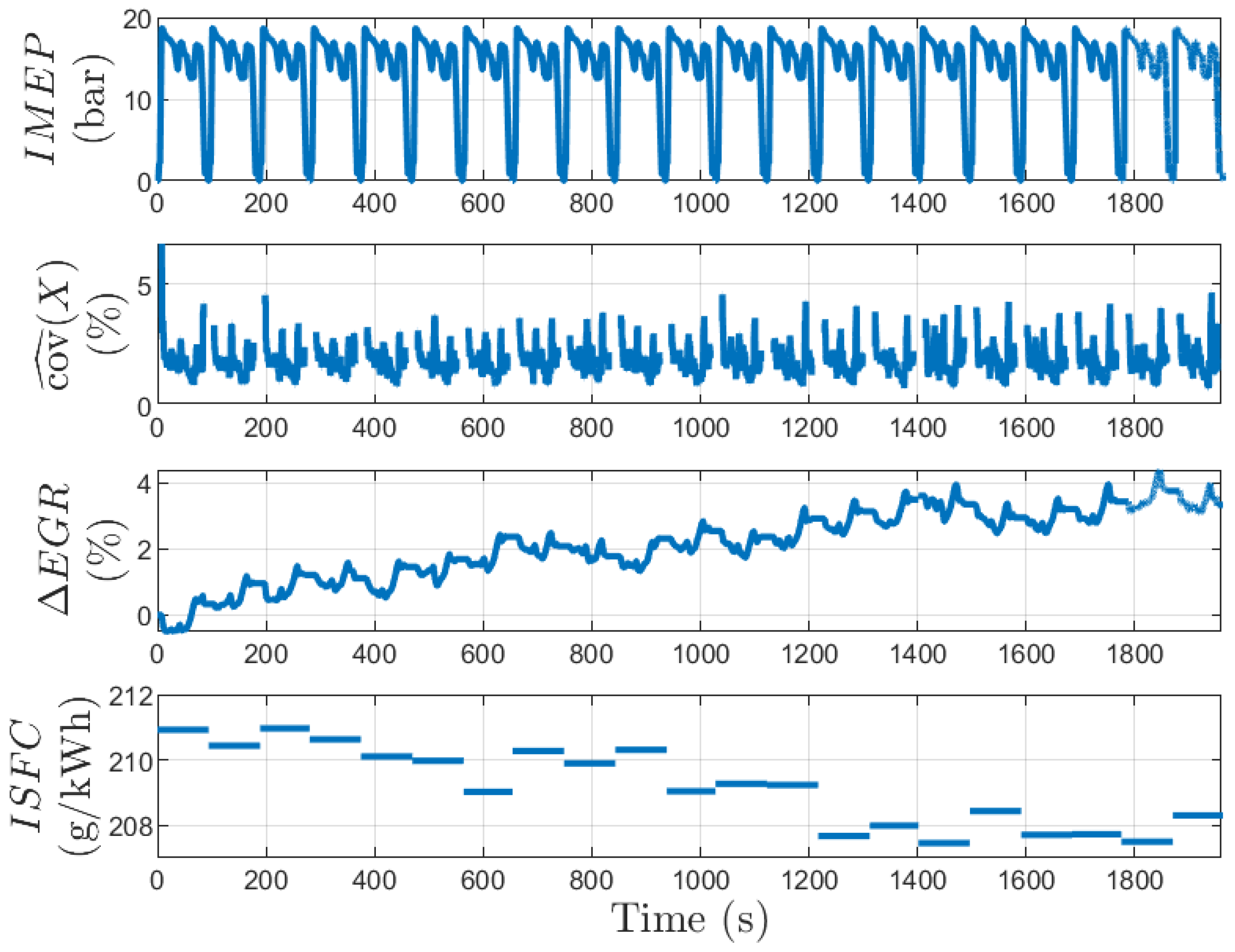
Figure 8 shows the behaviour of the controller during the 21 patterns. At the beginning of the test, EGR setpoint is set to its feedforward mapped value (as discussed previously, this value is derated to take into account estimation uncertainties and variation of environmental conditions). The objective of this experiment is to show the benefit of the feedback loop over consumption. From the first to the 16th cycle, the average along each pattern has increased of 0.1%. After 16 repeated patterns, the controller achieves the stabilisation of the offset at +3.5% (third plot). When the controller converges, there is a 1.7% gain in in regard to the initial conditions. The correction maintains its average value during the next 5 patterns. The experiment shows that the controller can shift a conservative calibration map towards the limit of stability until reaches the target (2%). No misfires were observed during the cycle.
6. Conclusions
This paper presents a first experimental implementation of a feedback loop control of the rate ensuring higher efficiency while avoiding unstable combustion. An online estimation of the Coefficient of Variance of the engine for control purposes has been proposed. It has been used to add a correction to the propositioning map. It allows us to maintain the engine near the limit of stability and alleviates the efficiency losses due to the conservative prepositioning map. The simple implementation proposed in the paper applies a global correction on the map, given by an integral controller and based on the error between the maximum (among the cylinders) estimated Coefficient of Variance and a target value. Further studies could focus on adaptive map implementations.
Experimental results showed, on a repetition of a portion of hybrid WLTP cycle, that the controller moves the engine towards the limit of stability, and that it converges before reaching the unstable domain. The test cycle is relevant since it explores limited areas of high efficiency of the engine operating map. This area is small because it corresponds to a hybridized architecture which limits the transient rates. This algorithm could be easily implemented with no extra costs in engines already equipped with in-cylinder pressure sensors and could improve the engine efficiency by a few percent.
Author Contributions
Conceptualization, M.J. and T.L.; methodology, M.J.; software, P.G.; validation, P.G., M.J. and T.L.; formal analysis, M.J. and P.G.; investigation, M.J. and P.G.; writing-review and editing, M.J., P.G. and T.L.; visualization, M.J. and P.G.; supervision, T.L.; project administration, T.L. All authors have read and agreed to the published version of the manuscript.
Funding
This research received no external funding.
Acknowledgments
The authors would like to acknowledge Adrien Nail, Gérard Martin and Ludovic Nowak for the fine work performed in operating the multicylinder engine.
Conflicts of Interest
The authors declare no conflict of interest.
References
- Kapus, P.; Ellinger, R.; Bogner, E.; Schrank, G.; Teuschl, G.; Sams, C.; Prochazka, W.; Fraidl, G. Passenger car powertrain 4. x–from vehicle level to a cost optimized powertrain system. In Proceedings of the 41st International Vienna Motor Symposium, Vienna, Austria, 22–24 April 2020; pp. 22–24. [Google Scholar]
- Gautrot, X.; Bardi, M.; Leroy, T.; Luca, P.; Nowak, L.; Reveille, B. Swumble In-Cylinder Fluid Motion for High Efficiency Gasoline SI Engines: Development of the second generation. In Proceedings of the SIA Powertrain and Electronics, Rouen, France, 3–4 June 2020. [Google Scholar]
- Kiwan, R.; Stefanopoulou, A.; Martz, J.; Surnilla, G.; Ali, I.; Styles, D. Effects of differential pressure measurement characteristics on low pressure-EGR estimation error in SI-engines. IFAC 2016, 49, 722–729. [Google Scholar]
- Nyerges, A.; Zoldy, M. Verification and Comparison of Nine Exhaust Gas Recirculation Mass Flow Rate Estimation Methods. Sensors 2020, 20, 7291. [Google Scholar] [CrossRef] [PubMed]
- Booven, B.; Schüle, H.; Walder, T.; Rottengruber, H. Potential of Series-Compatible In-Cylinder Pressure Sensors for Gasoline Engines Using the Example of Ignition Angle Control. In Proceedings of the International Conference on Knocking in Gasoline Engines, Berlin, Germany, 12–13 December 2017; pp. 279–296. [Google Scholar]
- Booven, B.; Schüle, H.; Walder, T.; Casal, K.; Rottengruber, H.; Bargende, M. Real-time assessment of in-cylinder pressure for fresh air mass estimation using the example of modern spark-ignited combustion engines. Int. J. Engine Res. 2018, 19, 250–256. [Google Scholar] [CrossRef]
- Maldonado, B.; Stefanopoulou, A.; Kaul, B. Artificial-intelligence-based prediction and control of combustion instabilities in spark-ignition engines. In Artificial Intelligence and Data Driven Optimization of Internal Combustion Engines; Elsevier: Amsterdam, The Netherlands, 2022; pp. 185–212. [Google Scholar]
- Singh, A.; Vance, J.B.; Kaul, B.; Drallmeier, J.; Jagannathan, S. Neural network control of spark ignition engines with high EGR levels. In Proceedings of the 2006 IEEE International Joint Conference on Neural Network Proceedings, Vancouver, BC, Canada, 16–21 July 2006; pp. 4978–4985. [Google Scholar]
- Norouzi, A.; Heidarifar, H.; Shahbakhti, M.; Koch, C.R.; Borhan, H. Model predictive control of internal combustion engines: A review and future directions. Energies 2021, 14, 6251. [Google Scholar] [CrossRef]
- Yao, C.; Hu, Y.; Zhou, T.; Yang, F.; Ouyang, M.; Huang, H. Combustion Stability Control of Dieseline PPCI Based on In-Cylinder Pressure Signals. IFAC PapersOnLine 2016, 49, 333–339. [Google Scholar] [CrossRef]
- Haertl, S.; Kainz, J.; Schuele, H.; Gaderer, M. Experimental Investigation of a Control Strategy Based on Combustion Stability and Combustion Phasing for a Multi-Cylinder Engine with Fueled Pre-Chambers and Cylinder Pressure Transducers; Technical Report, SAE Technical Paper; SAE International: Warrendale, PA, USA, 2021. [Google Scholar]
- Wei, H.; Zhu, T.; Shu, G.; Tan, L.; Wang, Y. Gasoline engine exhaust gas recirculation—A review. Appl. Energy 2012, 99, 534–544. [Google Scholar] [CrossRef]
- Tornatore, C.; Bozza, F.; De Bellis, V.; Teodosio, L.; Valentino, G.; Marchitto, L. Experimental and numerical study on the influence of cooled EGR on knock tendency, performance and emissions of a downsized spark-ignition engine. Energy 2019, 172, 968–976. [Google Scholar] [CrossRef]
- Randolph, E.; Fieseler, K.; Conway, G.; Alger, T.; Chadwell, C. The Effects of EGR Composition on Combustion Performance and Efficiency. SAE Int. J. Adv. Curr. Pract. Mobil. 2020, 3, 250–261. [Google Scholar] [CrossRef]
- Byttner, S.; Rögnvaldsson, T.; Wickström, N. Estimation of Combustion Variability Using in-Cylinder Ionization Measurements; SAE Technical Paper; SAE International: Warrendale, PA, USA, 2001; pp. 1–3485. [Google Scholar]
- Kaiadi, M.; Tunestål, P.; Johansson, B. Closed-Loop Combustion Control Using Ion-Current Signals in a 6-Cylinder Port-Injected Natural-Gas Engine; SAE Technical Paper; SAE International: Warrendale, PA, USA, 2008; pp. 1–2453. [Google Scholar]
- Byttner, S.; Holmberg, U. Closed-loop control of EGR using ion currents. In Proceedings of the 27th IASTED International Conference on Modelling, Identification, and Control, Innsbruck, Austria, 11–13 February 2008; p. 7. [Google Scholar]
- Leroy, T.; Nowak, L.; Odillard, L.; François, D. New Combustion Process for Higher Efficiency of Gasoline Engines. MTZ Worldw. 2021, 82, 16–25. [Google Scholar] [CrossRef]
- Grondin, O.; Duval, L.; Guillemin, F.; Ker, S.; Corde, G.; Vigild, C. Rapid-prototyping multi-sensors processing platform for real time engine control and diagnosis. IFAC 2007, 40, 555–562. [Google Scholar] [CrossRef]
- Vollberg, D.; Wachter, D.; Kuberczyk, T.; Schultes, G. Cylinder pressure sensors for smart combustion control. J. Sens. Sens. Syst. 2019, 8, 75–85. [Google Scholar] [CrossRef]
- Hellemans, A.; Landrevie, L.; Venzal, S.; Walker, E. In-cylinder pressure sensor. MTZ Worldw. EMag. 2011, 72, 42–48. [Google Scholar] [CrossRef]
- Leroy, T.; Nowak, L.; Gautrot, X.; Alvarado, L.M. Swumble 3-Cylinder High Efficiency Gasoline Engine for Future Electrified Powertrains. In Proceedings of the 42nd International Vienna Motor Symposium, Online, 29–30 April 2021. [Google Scholar]
Figure 1.
Evolution of the Indicated Specific Fuel Consumption () and of the estimated engine stability , function of EGR rate.
Figure 1.
Evolution of the Indicated Specific Fuel Consumption () and of the estimated engine stability , function of EGR rate.

Figure 2.
EGR calibration. ➀ Calibration set point. ➁ Optimal value.
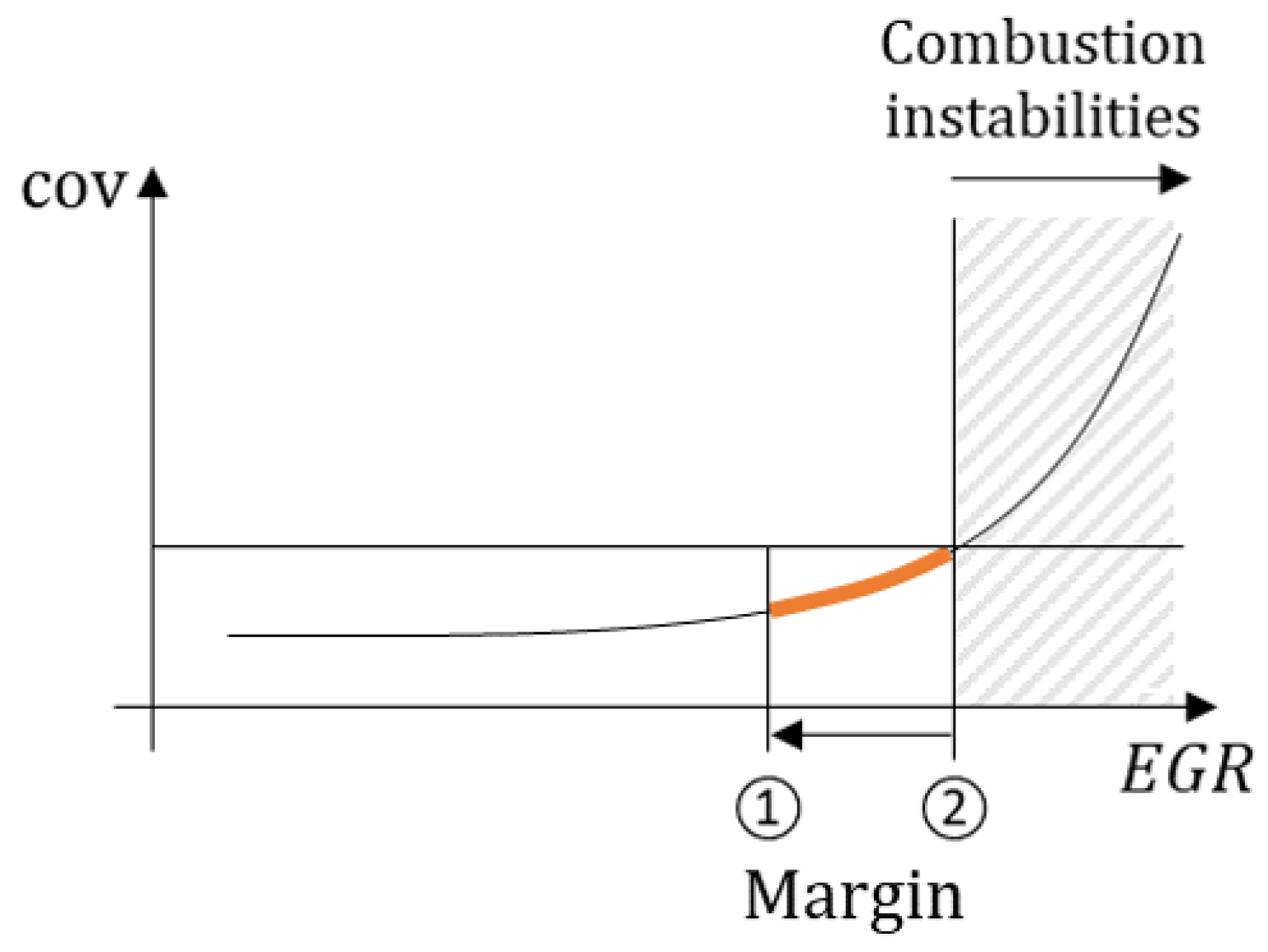
Figure 3.
Portion of WLTP cycle. Top plot: , middle plot: X defined Equation (2), bottom plot: estimators. A clear bias of the first stability estimator can be seen during transient states.
Figure 3.
Portion of WLTP cycle. Top plot: , middle plot: X defined Equation (2), bottom plot: estimators. A clear bias of the first stability estimator can be seen during transient states.
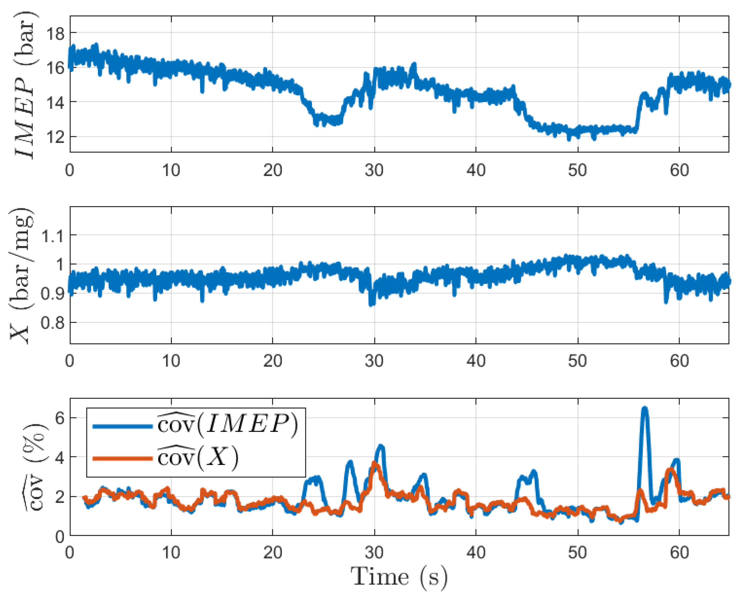
Figure 4.
Prototype engine.

Figure 5.
Engine control architecture.

Figure 6.
Hybrid vehicle typical transient trajectory for strategy validation.
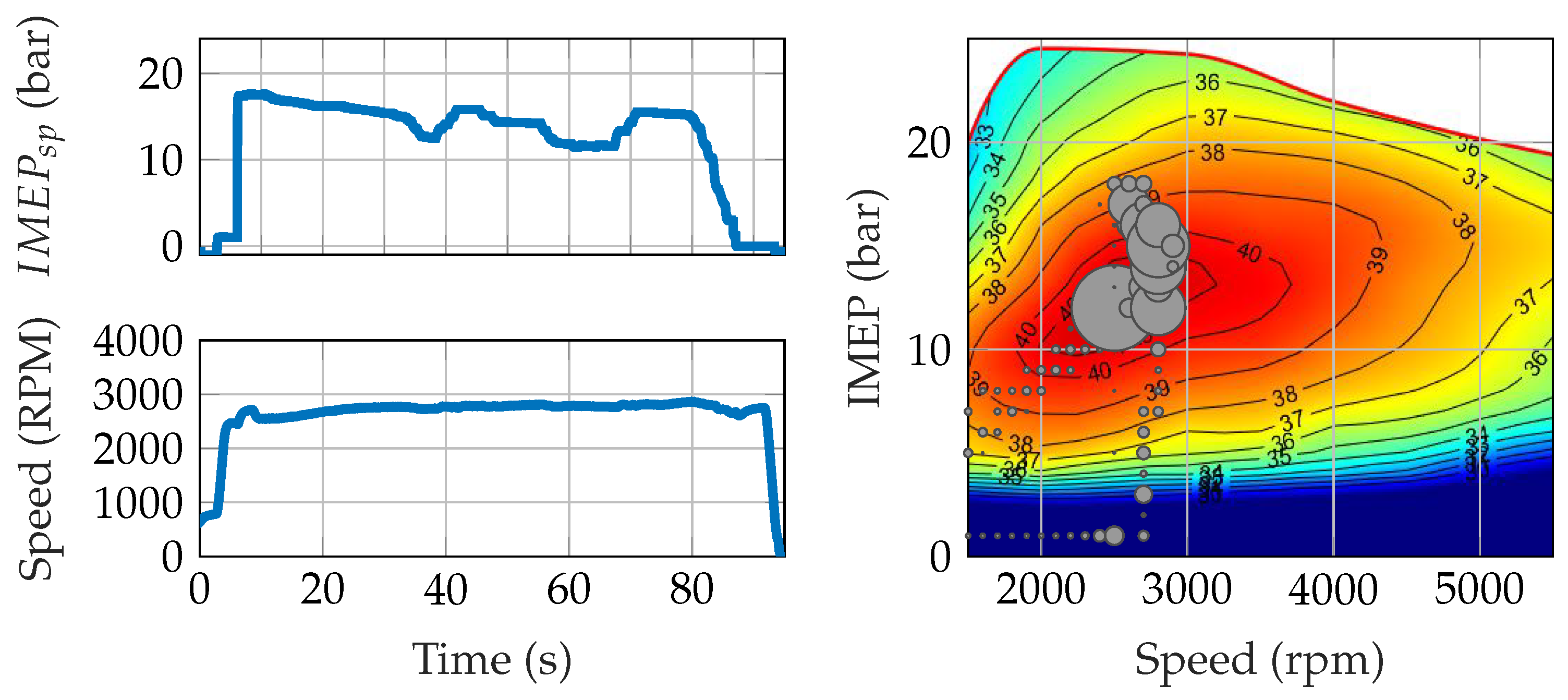
Figure 7.
Control of the offset during one pattern of WLTP cycle. Top plot: of the third cylinder and set point . Middle plot: maximum estimated over the 3 cylinders and its target . Bottom plot: correction .
Figure 7.
Control of the offset during one pattern of WLTP cycle. Top plot: of the third cylinder and set point . Middle plot: maximum estimated over the 3 cylinders and its target . Bottom plot: correction .
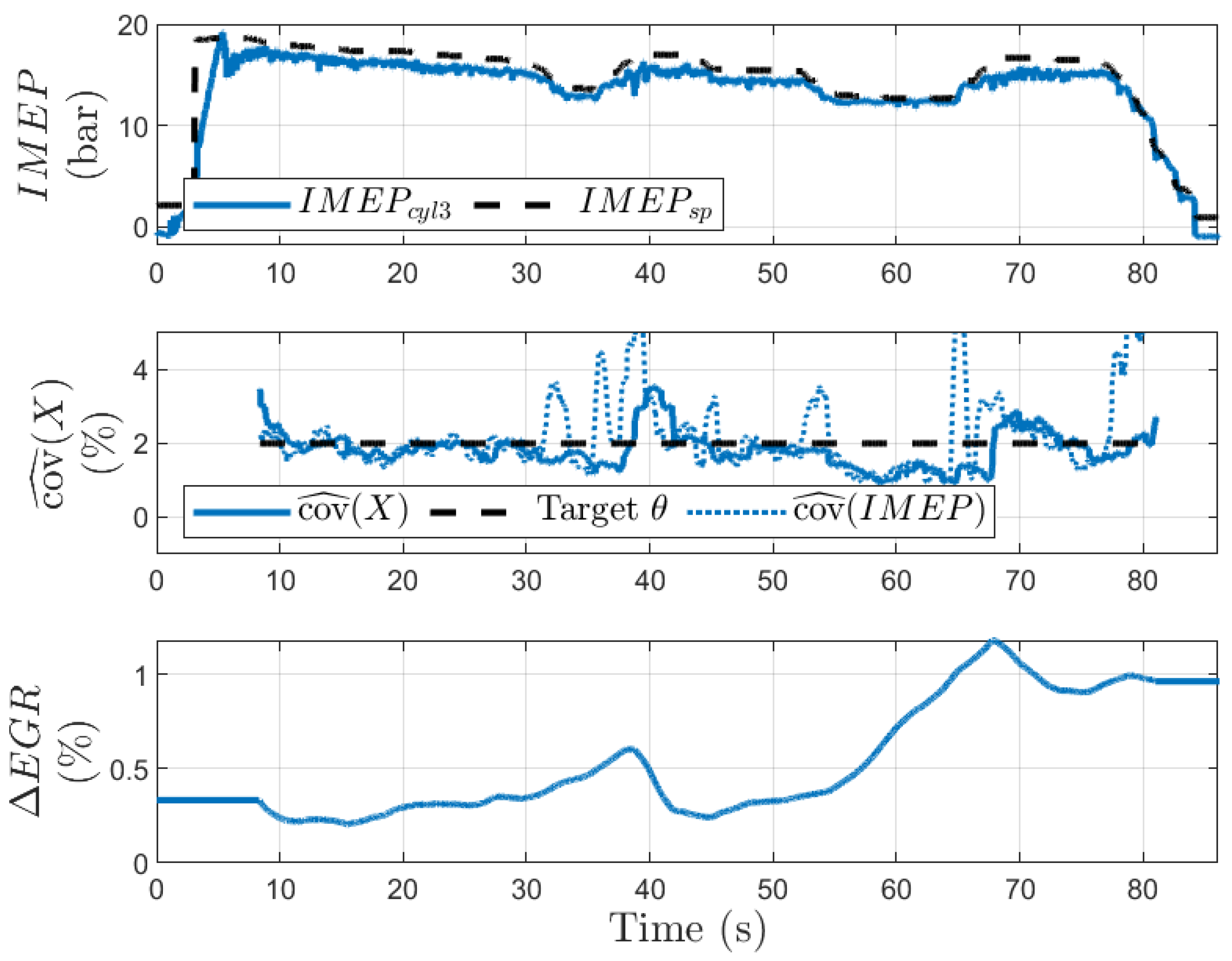
Figure 8.
Control of the offset subject to repeated pattern of a portion of WLTP cycle.

Table 1.
Multi-cylinder engine main features.
| Engine displacement [L] | 1.2 |
| Vol. compression ratio [-] | 13.65:1 |
| Bore × Stroke [mm] | 75 × 90.5 |
| Number of intake/exhaust valves | 2/2 |
| Valve lift CA duration, at 1 mm [°C A] | Intake 140, Exhaust 210 |
| Injection system | Central direct injection |
| Injector | Bosch HDEV6, six holes |
| Injection pressure [bar] | 350 |
Publisher’s Note: MDPI stays neutral with regard to jurisdictional claims in published maps and institutional affiliations. |
© 2022 by the authors. Licensee MDPI, Basel, Switzerland. This article is an open access article distributed under the terms and conditions of the Creative Commons Attribution (CC BY) license (https://creativecommons.org/licenses/by/4.0/).
Share and Cite
MDPI and ACS Style
Jean, M.; Granier, P.; Leroy, T. Combustion Stability Control Based on Cylinder Pressure for High Efficiency Gasoline Engines. Energies 2022, 15, 2530. https://doi.org/10.3390/en15072530
AMA Style
Jean M, Granier P, Leroy T. Combustion Stability Control Based on Cylinder Pressure for High Efficiency Gasoline Engines. Energies. 2022; 15(7):2530. https://doi.org/10.3390/en15072530
Chicago/Turabian StyleJean, Maxime, Pascal Granier, and Thomas Leroy. 2022. "Combustion Stability Control Based on Cylinder Pressure for High Efficiency Gasoline Engines" Energies 15, no. 7: 2530. https://doi.org/10.3390/en15072530
Note that from the first issue of 2016, this journal uses article numbers instead of page numbers. See further details here.