
Decentralized Model-Predictive Control of a Coupled Wind Turbine and Diesel Engine Generator System


1
Department of Electrical and Computer Engineering, New Jersey Institute of Technology, Newark, NJ 07102, USA
2
School of Applied Engineering and Technology, New Jersey Institute of Technology, Newark, NJ 07102, USA
*
Author to whom correspondence should be addressed.
Energies 2022, 15(9), 3349; https://doi.org/10.3390/en15093349
Submission received: 6 April 2022
/
Revised: 28 April 2022
/
Accepted: 29 April 2022
/
Published: 4 May 2022
(This article belongs to the Special Issue Predictive Control: A Modernized Control Approach for High Performance Electrical Energy Systems (Theory and Practice))
Abstract
:It is highly critical that renewable energy-based power generation units provide continuous and high-quality electricity. This requirement is even more pronounced in standalone wind–diesel systems where the wind power is not always constant or available. Moreover, it is desired that the extracted power be maximized in such a way that less fuel is consumed from the diesel engine. This paper proposes a novel method to design decentralized model-predictive controllers to control the frequency and power of a single standalone generation system, which consists of a wind turbine subsystem mechanically coupled with a diesel engine generator subsystem. Two decentralized model-predictive controllers are designed to regulate the frequency and active power, while the mechanical coupling between the two subsystems is considered, and no communication links exist between the two controllers. Simulation results show that the proposed decentralized controllers outperform the benchmark decentralized linear-quadratic Gaussian (LQG) controllers in terms of eliminating the disturbances from the wind and load power changes. Furthermore, it is demonstrated that the proposed control strategy has an acceptable robust performance against the concurrent variations in all parameters of the system as compared to the LQG controllers.
1. Introduction
The main source of electricity generation in remote regions is diesel engine generators (DEG), which are stable and controllable sources of energy. DEGs require large amounts of oil to operate which are very costly (cost of fuel, transportation, and storage) and also cause pollution in the environment. Renewable-based energy sources are the best alternative solutions to address these issues. Due to the wind abundance in remote areas, wind-based power generation systems are used to decrease the fuel consumption in diesel engines [1]. Standalone mechanically coupled wind-turbine and diesel engine generator systems are specifically suitable for remote areas, such as rural communities in Alaska [2].
The wind and load powers have irregular natures, and their sudden changes cause issues, especially in standalone systems where there is no stable grid power [3]. The intermittent behaviors of wind and load powers can affect the supply–demand balance, and cause instability in the frequency and active powers. Thus, advanced controllers are designed for such systems to smoothen the transient profile of frequency and active power in the presence of such variations and disturbances. Moreover, energy storage systems (ESSs) such as battery banks, superconductivity magnetic energy storage, compressed-air energy storage, and flywheels can be utilized to reduce the negative impacts of these instabilities [4].
There are several studies in the literature to address the problem of frequency and active power control in standalone wind–diesel systems. These systems include two subsystems, and the preferred choice is to design decentralized controllers for the two subsystems. Decentralized control configurations are more reliable than centralized ones, since they do not require high-speed communication links among controllers. Therefore, the adverse effects of communication failures or delays on the system are eliminated. Another advantage is that a single failure in one local controller does not affect the entire control system [5]. Another application of decentralized controllers can be found in robot manipulators where there exist a set of second-order subsystems for which separate controllers are designed [6]. In the following, some of the recent studies performed on the frequency and active power control of standalone wind–diesel systems are reviewed.
In [7], authors design two types of controllers, namely, proportional–integral (PI) and proportional–integral–derivative (PID) to regulate the frequency and active power of a standalone wind–diesel system. The parameters of the controllers are tuned using genetic algorithm (GA) and particle swarm optimization (PSO). In [8], authors carry out a comparative study of scaling-factor (SF)-based fuzzy logic controller (FLC) (SF–FLC), SF–FLC with PI (SF–FLC–PI) controller, SF–FLC with PD (SF–FLC–PD) controller, and SF–FLC with PID (SF–FLC–PID) controller to damp the frequency and power deviations of an isolated hybrid power system. Quasi-oppositional harmony search (QOHS) algorithm is used to optimize the controller parameters. The study in [3] presents a design strategy for a robust PI controller to balance frequency oscillations in a remote microgrid power system. The proposed controller is a conventional PI controller. An inverse additive perturbation is formed as an optimization problem securing the robustness of the proposed PI controller. The GA is utilized to tune and optimize the proposed PI controller parameters.
In [9], a two-level control methodology is presented to alleviate the frequency fluctuations in the wind–diesel standalone microgrid. At the first level, from the wind turbine generator (WTG) side, a constant wind power control signal is replaced by an optimum adaptive wind power control signal considering the power system operation and wind speed status. The proposed approach makes the microgrid frequency variations stay within the limits in all operating points. The study performed in [10] proposes a fractional order (FO) PID (FO-PID) controller for load–frequency control (LFC) of an isolated hybrid power system, including a biomass-based diesel engine generator and a wind turbine generator. The FO-PID controllers are the PID controllers but with different order of the integral and derivative parts. In [11], authors present robust fuzzy controllers that include super-magnetic energy storage units to mitigate the frequency variations in a standalone hybrid wind–diesel system. In [12], a robust decentralized control system is presented for automatic voltage regulation (AVR) and LFC of a generator in an isolated microgrid with multiple distributed generation systems. This control scheme is applied to an off-grid microgrid that includes renewable distributed generation and energy storage systems.
The work carried out in [13] presents an optimal decentralized controller for the LFC of a multi-area islanded grid with various synchronous generation systems. The decentralized controllers consist of various PI controllers that are concurrently modeled and optimized by using a classical descent-direction quasi-Newton-based approach. In [14], authors propose the design of decentralized overlapping decomposition controllers to regulate the frequency and active power of a storage-based wind–diesel system. The optimal control used in this study is based on linear quadratic regulator (LQR) controllers. In [15], a novel double equivalent-input-disturbance (EID) controller is presented for the frequency control of an isolated wind–diesel microgrid. In this integrated control structure, one single EID controller is applied to the pitch angle control system to mitigate the output power of the wind turbine generator by controlling the pitch angle. Another single EID controller is applied to the diesel generator side to adapt the output power of the diesel generator to balance the power of the system and keep the frequency in the normal range.
In [16], authors propose PI controllers to minimize the frequency deviations in a wind–diesel system. The parameters of the PI controllers are tuned using D-partition method. In the study carried out in [17], fuzzy-PID controllers are designed for a two-area wind–diesel system. The fuzzy-PID control parameters are tuned using lighting flash algorithm in order to improve the flexibility of the system against disturbances in the frequency. In [18], a hybrid dragonfly algorithm and pattern search method (HDA-PS) is presented to optimize the parameters of a two-degrees-of-freedom PID controller for the LFC of a multi-microgrid system. The frequency control objective is formulated as an optimization problem under stochastic disturbances, and HDA-PS is used to achieve the optimal control parameters. In [19], the design of decentralized optimal controllers is proposed to regulate the frequency and power of a mechanically coupled wind–diesel system. The decentralized control structure includes two PI-lead controllers that are implemented and optimized concurrently using a quasi-Newton-based optimization approach.
In this study, decentralized model-predictive controllers (MPCs) are designed in a sequential way to address the frequency and active power regulation of a standalone wind–diesel system. This sequential decentralized MPC controller design method is proposed for the first time in this study. The proposed MPC scheme provides an optimal solution to a quadratic cost function based on the dynamic model of the system. This control strategy calculates the optimal control signal subject to the given constraints on the output frequency deviation and the load change. The performance of the proposed decentralized MPC scheme is analyzed by injecting step and random disturbances in the wind and load powers, as well as changing the model parameter values. It should be pointed out that since MPC is an optimal control strategy, the decentralized LQG controllers are chosen as a benchmark due to their optimal control feature. Another important point to mention is that voltage variations are not studied in this paper due to the fact that voltage control loop has faster dynamics compared to the frequency control loop, and their controllers are designed separately [12]. The main contributions of this paper are listed as follows:
- Designing the decentralized MPC controllers without communication links using a sequential method.
- Performing extensive simulations to show the superior performance of the proposed decentralized MPC in reducing the effect of disturbances in the wind and load power variations, as well as its robustness against all parameter changes as compared to the decentralized LQG method (benchmark).
The rest of the paper is summarized as follows. The standalone wind–diesel system and the dynamical models for each subsystems are presented in Section 2. Section 3 describes the MPC methodology and the design of decentralized controllers using sequential strategy. In Section 4, simulation results are presented to assess the performance of the proposed decentralized MPC controllers in terms of damping the disturbances from the wind and load power changes. Furthermore, the robustness of the proposed controller against all parameter variations of the system is analyzed. Finally, the conclusions are summarized in Section 5.
2. Model of the Standalone System
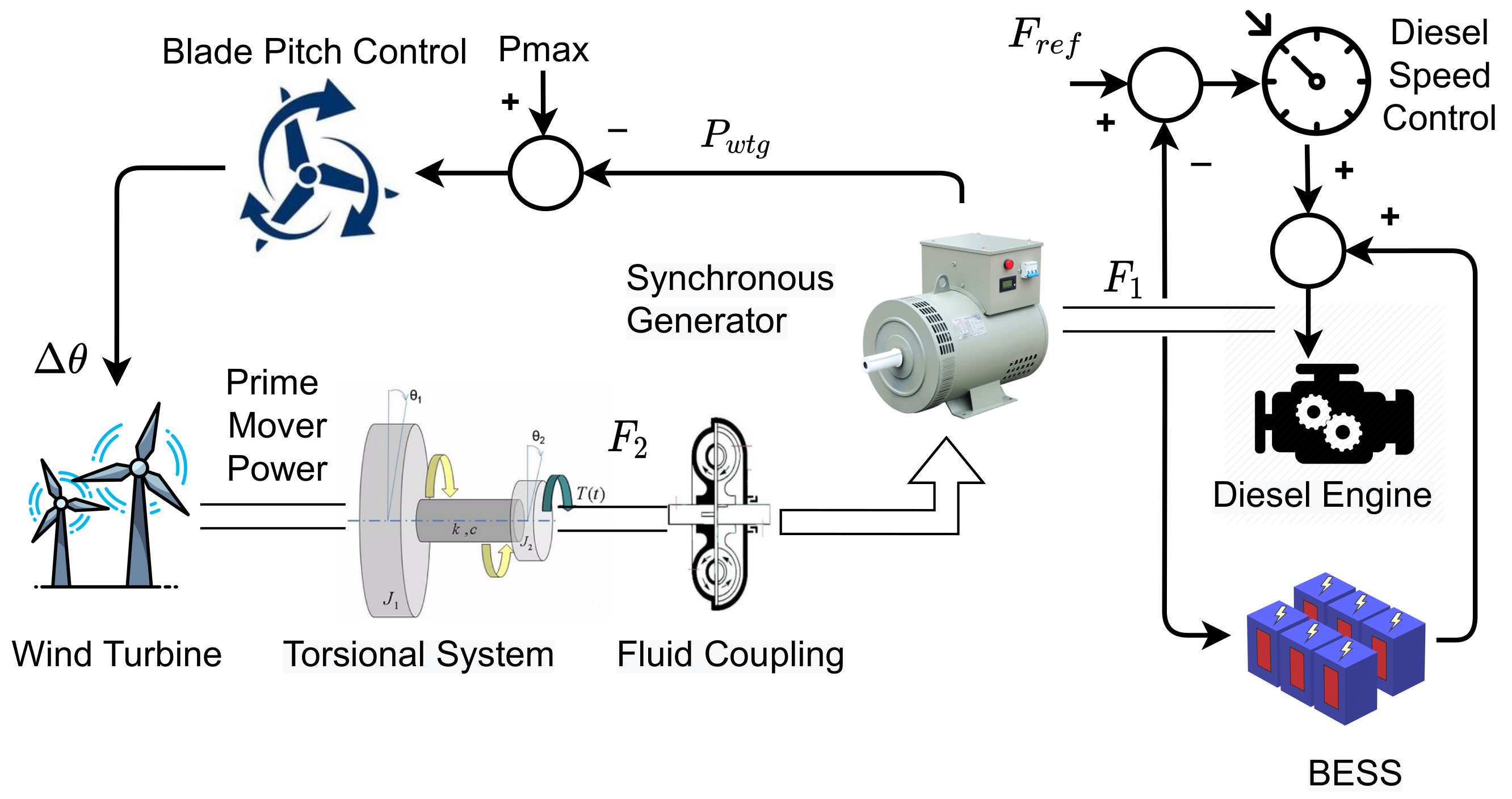
The wind–diesel system studied in this paper consists of several modules, such as a synchronous generator driven by a diesel engine, diesel engine speed controller, battery energy storage system (BESS), wind turbine, torsional system, fluid coupling, and blade pitch controller. Figure 1 shows a general diagram of this system. This standalone system is suitable for remote and isolated regions such as rural areas in Alaska, where there is no power source from the main grid, and their electricity is mainly generated via diesel engine generators [2]. By connecting a wind turbine shaft to such diesel engine generators using a fluid coupling system, the fuel consumption by the diesel engines can be reduced. Moreover, another advantage of such systems is that the wind turbine does not require a dedicated generator that is more cost-effective. The main control objectives in this system are to keep the diesel engine speed at a set-point level, and the turbine active power at the desired level. Furthermore, the dynamic equations of the wind–diesel system are linearized around the nominal operating point for stability and small signal analyses [20].
The mechanically coupled wind–diesel system is shown in more detail in Figure 2, where subsystems 1 and 2 represent the modules in the diesel engine generator and wind turbine systems, respectively. As shown in Figure 2, the frequency error signal is fed into the speed controller of the diesel engine (controller 1) based on which the control signal is generated. Then, this control signal tries to adjust the fuel valve () to produce the required power to the diesel engine. In addition, the BESS behaves as a short-term backup generation unit to help the regulation of the frequency. The transfer functions of the wind–diesel subsystem (first subsystem) are as follows [14]:
In the second subsystem, the power error signal is generated based on the difference between the set-point power () and the power generated by the wind turbine, and is transferred through the fluid coupling (). Then, this signal is fed into the pitch angle controller (controller 2) to tune the hydraulic pitch actuator () to change the pitch angle of the wind turbine for extracting the maximum power. The wind turbine pitch response indicates a specific characteristic of the turbine and is defined as the diversion from the optimal pitch angle as a response to the direction of the wind [21]. This pitch response is modeled using a lag transfer function called datafit pitch response. It is to be noted that a wind turbine with variable blades operates efficiently during irregular wind speeds. The fluid coupling module () is responsible for connecting the diesel generator and wind turbine shafts through a fluid coupling system, which is an alternative for a mechanical clutch [22]. This module transfers the power from the wind turbine to the diesel engine when the wind turbine rotor speed is more than that of the diesel engine. The blade characteristics gain generates power that is proportional to the angle of the turbine pitch. The second subsystem has the following transfer functions [14]:
3. Model-Predictive Control Design
In this section, a brief introduction to the MPC controller and its structure and design are presented. Then, the decentralized solution to the model introduced in Figure 1 is provided.
3.1. MPC Methodology
MPC is an advanced control method used in several applications such as chemical processes, petrol industry, electromechanical systems, etc. [23]. It is based on a predictive-based control scheme in which an optimum control action is achieved over a predefined prediction horizon at every sampling interval. The optimization process tries to minimize the difference between the predicted and reference response as well as the control effort, subject to some constraints.
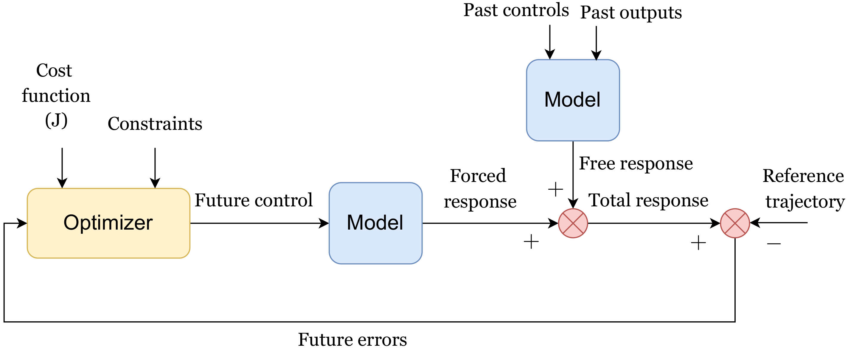
Figure 3 demonstrates the main structure of the MPC system. The future plant outputs are predicted by using an internal model based on the past and current values of the inputs and outputs as well as on the optimal future control actions. The total prediction consists of two components: the free and forced responses. The former is defined as the expected behavior of the output assuming that the future control actions are zero, while the latter represents the additional component of the output due to the possible set of future controls. For linear systems, these two responses are added together to calculate the total prediction signal. Moreover, the reference trajectory signal is the desired values that the output should track. The role of the optimizer is basically to calculate the best set of future control signals by minimizing a cost function (J). This optimization problem is subject to constraints on both manipulated and control variables [24].
The main objective in MPC is to minimize the future output error with minimum control effort. The cost function to be minimized is defined as a weighted sum of squared predicted errors and squared future control actions [23]:
where and are the output lower and upper prediction horizons, respectively, is the control horizon, and and are weighting factors. The reference trajectory across the future limit N is represented by . It should be noted that the control effort is allowed to be minimized over the control horizon according to the following equation [23]:
In addition, the cost function has constraints over the manipulated (control) and output variables as well as the rate of manipulated variable, as follows [23]:
The optimal sequence of the control action is achieved by minimizing Equation (9) over the horizon N subject to the constraints of Equations (10) and (11).
While providing an easy-to-apply optimal control scheme, MPC has several advantages, including fast response and robustness against system uncertainties, as well as nonlinearities [25]. However, this control technique needs the knowledge of the entire system model which, together with the associated control constraints, makes it a more complex controller as compared to the conventional controllers such as PID. Moreover, because of the internal real-time optimization stage in the controller, the control algorithm is time-consuming.
3.2. Decentralized MPC
In this subsection, decentralized MPC controllers are designed for the two subsystems introduced in Figure 2. The design is based on a sequential procedure. In this procedure, the first MPC controller is designed for the first subsystem (diesel generator subsystem). Then, while the first MPC is in place and the first control loop is closed, the second subsystem is connected to the first subsystem through the fluid coupling module, and the second MPC controller is designed for the entire system. Figure 4 demonstrates the sequential design of the MPC controller for the mechanically coupled wind–diesel system.
In the next section, the proposed sequential decentralized MPC design technique is applied to the mechanically coupled diesel generator and wind turbine subsystems, and the simulation results are demonstrated and analyzed.
4. Simulation Results
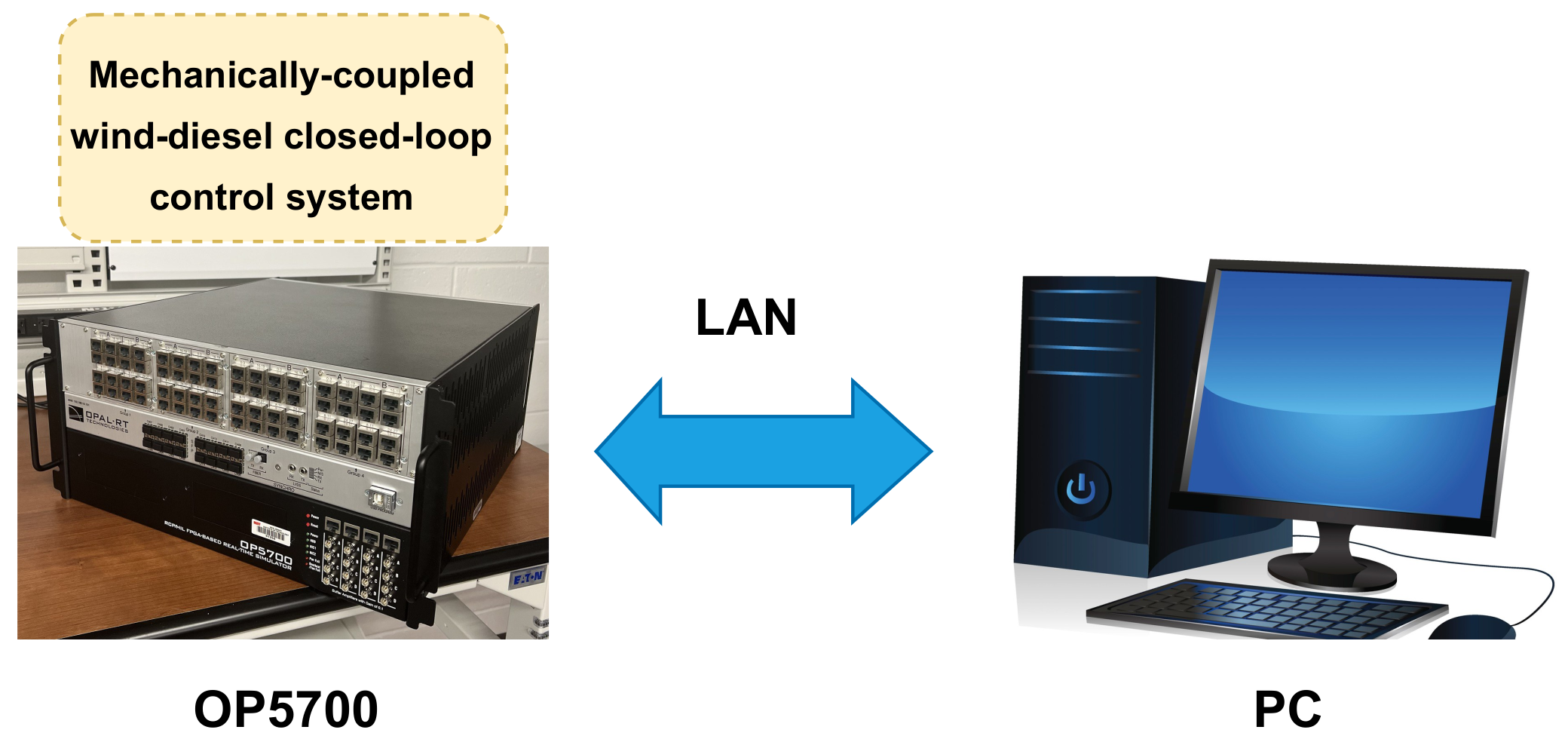
Simulation results for the proposed decentralized MPC designed for the wind–diesel system shown in Figure 2 are presented in this section. The results are based on the real-time simulations using OPAL-RT (OP5700) simulator (Manufactured in QC, Canada) and MATLAB/SIMULINK R2019a software (1994-2022 The MathWorks, Inc., Portola Valley, CA, USA). OP5700 contains a powerful computer which has a linux-based real-time operating system, and its CPU specifications are Intel Xeon E5, 8 Cores, 3.2 (GHz), and 20 (MB) cache memory. The wind–diesel closed-loop control system shown in Figure 2 is simulated in the Simulink environment, which is connected to RT-Lab software in OP5700. Then, the simulation results are transmitted to a regular PC using an LAN cable and are shown in Matlab environment in Windows operating system, as demonstrated in Figure 5. Moreover, the fixed-step size of the real-time simulation is chosen using trial-and-error procedure in such a way that there is no discontinuity in the real-time waveforms of the outputs. This fixed-step size is chosen to be . In addition, the solver is ode4 (Runge–Kutta). The model parameter values are listed in Table 1. The decentralized MPC parameters for both controllers are shown in Table 2.
Before delving into the details of the simulation results, it should be pointed out that the fixed variable that appeared in the wind–diesel model in Figure 1 is the reference frequency set-point () for the diesel engine generator, and that is why its variations are considered to be zero ( in Figure 2). Similarly, the demanded power from the wind turbine is a constant value (), and, hence, . Therefore, the assessments of the controllers are performed based on the disturbances resulting from the wind and load power changes. It should also be noted that the maximum allowable frequency variation lies in the range of 0.1–0.2 (Hz).
The first case study is to analyze the robust performance of the proposed decentralized MPC controllers against disturbances in the load and wind powers. As mentioned before, sudden changes in the wind and load power are common in such systems because of the volatile nature of the wind power and electricity consumption (load) at the consumer side. Figure 6 shows that both decentralized MPC and LQG controllers are capable of damping the distortions in the frequency and turbine power errors. However, MPC controllers can remove those undesired oscillations much faster than the LQG controllers because of their capability of predicting the future disturbances. Table 3 demonstrates a quantitative performance comparison between the proposed method and the benchmark LQG. It should be pointed out that the LQG control minimizes the cost function , where x and u are the state and input vectors, respectively. Moreover, the weight (covariance) matrices are chosen to be and for the first controller, and and for the second controller, respectively. In addition, the process and measurement noise covariance matrices are chosen to be and for the first controller, and and for the second controller, respectively [26].
In the second case study, the effect of random fluctuations (variations) in the wind and load powers on the performance of the control system is investigated. These random fluctuations that are generated based on the models presented in [27] are depicted in Figure 7. The performances of both decentralized controllers are shown in Figure 8. The mean squared error (MSE) is used to compare the performance of the two decentralized controllers. The MSE of frequency and active power variations for the proposed decentralized MPC controllers are equal to and , respectively, while for the benchmark LQG controllers, these errors are equal to and , respectively. It is clearly observed that the proposed decentralized MPC controllers outperform the benchmark LQG controllers.
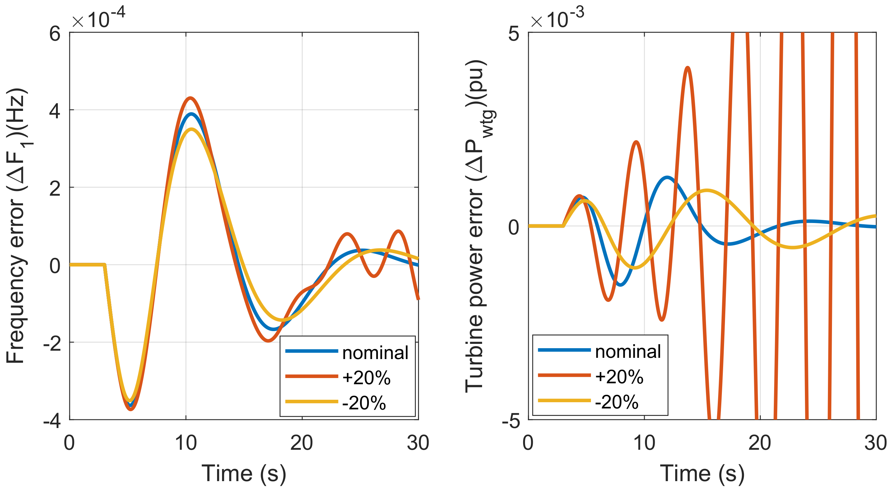
Another case study was performed to assess the decentralized control systems in terms of robustness against the internal parameter variations. Figure 9 demonstrates the robust performance of the proposed decentralized MPC controllers against concurrent changes of all subsystems parameters in Table 1. This performance is compared with that of the benchmark decentralized LQG controllers shown in Figure 10. It is observed that the proposed decentralized method has a better robust performance as compared to the benchmark method, in terms of both frequency and power variations. Moreover, Figure 10 shows that the performances of the decentralized LQG controllers deteriorate considerably for variations, and they become totally unstable for variation.
5. Conclusions
This paper proposes new robust decentralized model-predictive controllers to address the problem of frequency and active power regulation in a standalone wind–diesel system consisting of two subsystems, namely, diesel engine generator and wind turbine. The proposed MPC strategy provides an optimal solution to a quadratic cost function based on the dynamic model of the system. This control scheme calculates the optimal control signal subject to the given constraints on the output frequency deviation and the load change. The decentralized controllers are designed sequentially in such a way that there is no communication link between them. Moreover, the mechanical coupling between the two subsystems is taken into account in the controller design process. Simulation results are carried out to confirm the effectiveness of the proposed control technique. The results show that the proposed closed-loop system has a superior performance to the linear quadratic Gaussian controller in damping the undesired oscillations due to the disturbances resulting from abrupt wind and load power changes. Moreover, the robustness analysis demonstrates that the proposed control strategy is robust against subsystem parameter changes, while the benchmark technique shows a major performance deterioration for subsystems parameter changes, and is totally unstable for subsystems parameter changes. The future studies will be focused on the control of microgrids with high penetration of wind turbines that causes stability issues at large scales.
Author Contributions
Conceptualization, S.M.A.; methodology, M.S.; software, M.S.; validation, M.S.; data curation, M.S. and F.M.S.; writing—original draft preparation, M.S.; writing—review and editing, M.S., F.M.S. and S.M.A.; visualization, M.S. and F.M.S.; supervision, S.M.A.; funding acquisition, S.M.A. All authors have read and agreed to the published version of the manuscript.
Funding
This research received no external funding.
Institutional Review Board Statement
Not applicable.
Informed Consent Statement
Not applicable.
Data Availability Statement
Not applicable.
Conflicts of Interest
The authors declare no conflict of interest.
Abbreviations
The following abbreviations are used in this manuscript:
| Frequency error of the diesel generator subsystem (Hz) | |
| Frequency error of the wind turbine subsystem (Hz) | |
| Load power disturbance error (pu) | |
| Set-point frequency error (Hz) | |
| Control signal of the diesel generator subsystem (pu) | |
| Control signal of the wind turbine subsystem (pu) | |
| Wind turbine generator power error (pu) | |
| Turbine power disturbance error (pu) | |
| Total power set-point error (pu) | |
| (Hz) | |
| (pu) | |
| Actuator time constant 1 (s) | |
| Actuator time constant 2 (s) | |
| Actuator time constant 3 (s) | |
| Diesel engine gain | |
| Diesel engine time constant (s) | |
| Battery gain | |
| Battery time constant (s) | |
| Hydraulic pitch actuator gain | |
| Hydraulic pitch actuator time constant 1 (s) | |
| Hydraulic pitch actuator time constant 2 (s) | |
| Datafit pitch response gain | |
| Wind turbine gain | |
| Wind turbine time constant (s) | |
| Blade characteristic gain | |
| Fluid coupling gain |
References
- Kanchev, H.; Lu, D.; Colas, F.; Lazarov, V.; Francois, B. Energy Management and Operational Planning of a Microgrid With a PV-Based Active Generator for Smart Grid Applications. IEEE Trans. Ind. Electron. 2011, 58, 4583–4592. [Google Scholar] [CrossRef] [Green Version]
- Fay, G.; Schwoerer, T.; Keith, K. Alaska Isolated Wind–Diesel Systems Performance and Economic Analysis; Institute of Social and Economic Research, University of Alaska Anchorage: Anchorage, AK, USA, 2010; Available online: http://hdl.handle.net/11122/11951 (accessed on 25 September 2019).
- Nandar, C.S.A. Robust PI control of smart controllable load for frequency stabilization of microgrid power system. Renew. Energy 2013, 56, 16–23. [Google Scholar] [CrossRef]
- Khayyer, P.; Izadian, A. Power management strategies for hybrid electric trucks in smart-grids. In Proceedings of the 2012 IEEE PES Innovative Smart Grid Technologies (ISGT), Washington, DC, USA, 16–20 January 2012; pp. 1–3. [Google Scholar] [CrossRef]
- Gharehpetian, G.B.; Baghaee, H.R.; Shabestary, M.M. Chapter 2-Microgrid control strategies. In Microgrids and Methods of Analysis; Academic Press: Cambridge, MA, USA, 2021; pp. 7–58. [Google Scholar] [CrossRef]
- Yazdani, D.; Azizi, S.; Bakhshai, A. Designing a Decentralized LQ Controller for an Industrial Robot Manipulator Based on Optimization Techniques. IEEE Int. Symp. Ind. Electron. 2006, 4, 3078–3083. [Google Scholar]
- Gampa, S.R.; Das, D. Real power and frequency control of a small isolated power system. Int. J. Electr. Power Energy Syst. 2015, 64, 221–232. [Google Scholar] [CrossRef]
- Mahto, T.; Mukherjee, V. A novel scaling factor based fuzzy logic controller for frequency control of an isolated hybrid power system. Energy 2017, 130, 339–350. [Google Scholar] [CrossRef]
- Bhukya, L.; Annamraju, A.; Nandiraju, S. Robust frequency control in a wind–diesel autonomous microgrid: A novel two-level control approach. Renew. Energy Focus 2021, 36, 21–30. [Google Scholar] [CrossRef]
- Mahto, T.; Malik, H.; Mukherjee, V. Fractional Order Control and Simulation of Wind-Biomass Isolated Hybrid Power System Using Particle Swarm Optimization; Springer: Berlin/Heidelberg, Germany, 2019; pp. 277–287. [Google Scholar]
- Santhi, R.; Sudha, K. A robust decentralized controller for standalone wind systems and hybrid wind–diesel systems using type-2 fuzzy approach. Int. J. Signal Process. Syst. 2014, 2, 48–54. [Google Scholar]
- Azizi, S.M.; Khajehoddin, S.A. Robust decentralized voltage and frequency control of generators in islanded microgrids using μ-synthesis. In Proceedings of the IEEE Energy Conversion Congress and Exposition (ECCE), Milwaukee, WI, USA, 18-22 September 2016; pp. 1–8. [Google Scholar]
- Azizi, S.M.; Khajehoddin, S.A. Designing decentralized load-frequency controllers: An optimization approach for synchronous generators in islanded grids. IEEE Ind. Appl. Mag. 2018, 24, 67–74. [Google Scholar] [CrossRef]
- Khayyer, P.; Özgüner, Ü. Decentralized control of large-scale storage-based renewable energy systems. IEEE Trans. Smart Grid 2014, 5, 1300–1307. [Google Scholar] [CrossRef]
- Wang, C.; Li, J.; Hu, Y. Frequency control of isolated wind–diesel microgrid power system by double equivalent-input-disturbance controllers. IEEE Access 2019, 7, 105617–105626. [Google Scholar] [CrossRef]
- Veronica, A.J.; Kumar, N.S.; Gonzalez-Longatt, F. Design of load frequency control for a microgrid using D-partition method. Int. J. Emerg. Electr. Power Syst. 2020, 21, 20190175. [Google Scholar] [CrossRef]
- Kheshti, M.; Ding, L.; Askarian-Abyaneh, H.; Singh, A.R.; Zare, S.; Terzija, V. Improving frequency regulation of wind-integrated multi-area systems using LFA-fuzzy PID control. Int. Trans. Electr. Energy Syst. 2021, 31, 12802. [Google Scholar] [CrossRef]
- Mishra, S.; Prusty, R.C.; Panda, S. Design and analysis of 2dof-PID controller for frequency regulation of multi-microgrid using hybrid dragonfly and pattern search algorithm. J. Control. Autom. Electr. Syst. 2020, 31, 813–827. [Google Scholar] [CrossRef]
- Shojaee, M.; Azizi, S.M. Optimal decentralized control of a wind turbine and diesel generator system. Optim. Control. Appl. Methods 2021. [Google Scholar] [CrossRef]
- Kundur, P. Power System Stability; CRC Press: New York, NY, USA, 2007; pp. 1–7. [Google Scholar]
- Tan, J.L. Development of a Pitch Based Wake Optimisation Control Strategy to Improve Total Farm Power Production. Master’s Thesis, Uppsala University, Uppsala, Sweden, 2016. [Google Scholar]
- Prasetya, A.; Komarudin, U. Evaluation and Calculation Flens Clutch. Rev. Int. Geogr. Educ. Online 2021, 11, 408–416. [Google Scholar]
- Mohamed, T.; Bevrani, H.; Hassan, A.; Hiyama, T. Decentralized model predictive based load frequency control in an interconnected power system. Energy Convers. Manag. 2011, 52, 1208–1214. [Google Scholar] [CrossRef]
- Hu, J.; Shan, Y.; Guerrero, J.M.; Ioinovici, A.; Chan, K.W.; Rodriguez, J. Model predictive control of microgrids—An overview. Renew. Sustain. Energy Rev. 2021, 136, 110422. [Google Scholar] [CrossRef]
- Singh, A.; Sharma, V. Salp swarm algorithm-based model predictive controller for frequency regulation of solar integrated power system. Neural Comput. Appl. 2019, 31, 8859–8870. [Google Scholar] [CrossRef]
- MathWorks. LQG. Available online: https://www.mathworks.com/help/control/ref/ss.lqg.html (accessed on 5 April 2022).
- Das, D.C.; Roy, A.; Sinha, N. GA based frequency controller for solar thermal–diesel–wind hybrid energy generation/energy storage system. Int. J. Electr. Power Energy Syst. 2012, 43, 262–279. [Google Scholar] [CrossRef]
Figure 1.
The general configuration of the mechanically coupled wind–diesel system.

Figure 2.
Block diagram of the mechanically coupled wind–diesel system.

Figure 3.
The main structure of the MPC controller.

Figure 4.
Sequential design of the decentralized MPC controllers: (a) for subsystem 1 and (b) for subsystem 2 connected to subsystem 1 and in a closed-loop.
Figure 4.
Sequential design of the decentralized MPC controllers: (a) for subsystem 1 and (b) for subsystem 2 connected to subsystem 1 and in a closed-loop.

Figure 5.
Real-time simulation using OP5700.

Figure 6.
Robust performance of the proposed decentralized MPC and the benchmark decentralized LQG controllers against step disturbances in the load and wind powers applied at t = 10 (s) with the amplitude of 0.01 (pu).
Figure 6.
Robust performance of the proposed decentralized MPC and the benchmark decentralized LQG controllers against step disturbances in the load and wind powers applied at t = 10 (s) with the amplitude of 0.01 (pu).

Figure 7.
The profile of random variations in the wind and load powers based on [27].
Figure 7.
The profile of random variations in the wind and load powers based on [27].

Figure 8.
Performance of the proposed decentralized MPC and the benchmark decentralized LQG controllers in terms of the frequency and turbine power errors subject to random load and wind power disturbances shown in Figure 7.
Figure 8.
Performance of the proposed decentralized MPC and the benchmark decentralized LQG controllers in terms of the frequency and turbine power errors subject to random load and wind power disturbances shown in Figure 7.

Figure 9.
Robust performance of the frequency and turbine power error in the first and second subsystems against concurrent changes in all subsystems parameters for the proposed decentralized MPC controllers, subject to the load disturbance applied at with the amplitude of .
Figure 9.
Robust performance of the frequency and turbine power error in the first and second subsystems against concurrent changes in all subsystems parameters for the proposed decentralized MPC controllers, subject to the load disturbance applied at with the amplitude of .

Figure 10.
Robust performance of the frequency and turbine power error in the first and second subsystems against concurrent changes in all subsystems parameters for the decentralized LQG controllers, subject to the load disturbance applied at with the amplitude of .
Figure 10.
Robust performance of the frequency and turbine power error in the first and second subsystems against concurrent changes in all subsystems parameters for the decentralized LQG controllers, subject to the load disturbance applied at with the amplitude of .


Table 1.
Model parameters values.
| Subsystems | Parameter Values |
|---|---|
| First subsystem | , , , , , |
| Second subsystem | , , , , , , , |
Table 2.
Design parameters of the two decentralized controllers, and , for the two subsystems.
| Sample time = 0.0001 (s) Prediction horizon = 11 (s) Control horizon = 2 (s) Weights on control variables = 0.0003 Weights on control variable rates = 0.008 Weights on the output signals = 25 | Sample time = 0.0001 (s) Prediction horizon = 10 (s) Control horizon = 5 (s) Weights on control variables = 3 Weights on control variable rates = 5 Weights on the output signals = 20 |
Table 3.
Performance comparison between the decentralized MPC and LQG control schemes in terms of over/undershoot () and settling time () of the frequency and active power deviations.
Table 3.
Performance comparison between the decentralized MPC and LQG control schemes in terms of over/undershoot () and settling time () of the frequency and active power deviations.
| Technique | Load Increase | Wind Decrease | ||||||
|---|---|---|---|---|---|---|---|---|
| MPC | (Hz) | (pu) | 5 (s) | 3 (s) | (Hz) | (pu) | 15 (s) | 4 (s) |
| LQG | (Hz) | (pu) | 26 (s) | 25 (s) | (Hz) | (pu) | 27 (s) | 12 (s) |
Publisher’s Note: MDPI stays neutral with regard to jurisdictional claims in published maps and institutional affiliations. |
© 2022 by the authors. Licensee MDPI, Basel, Switzerland. This article is an open access article distributed under the terms and conditions of the Creative Commons Attribution (CC BY) license (https://creativecommons.org/licenses/by/4.0/).
Share and Cite
MDPI and ACS Style
Shojaee, M.; Mohammadi Shakiba, F.; Azizi, S.M. Decentralized Model-Predictive Control of a Coupled Wind Turbine and Diesel Engine Generator System. Energies 2022, 15, 3349. https://doi.org/10.3390/en15093349
AMA Style
Shojaee M, Mohammadi Shakiba F, Azizi SM. Decentralized Model-Predictive Control of a Coupled Wind Turbine and Diesel Engine Generator System. Energies. 2022; 15(9):3349. https://doi.org/10.3390/en15093349
Chicago/Turabian StyleShojaee, Milad, Fatemeh Mohammadi Shakiba, and S. Mohsen Azizi. 2022. "Decentralized Model-Predictive Control of a Coupled Wind Turbine and Diesel Engine Generator System" Energies 15, no. 9: 3349. https://doi.org/10.3390/en15093349
Note that from the first issue of 2016, this journal uses article numbers instead of page numbers. See further details here.