


Review on Separation Processes of End-of-Life Silicon Photovoltaic Modules
by
 , ,
, ,
Jongwon Ko
1,† ,
,
Kyunghwan Kim
1,†,
Ji Woo Sohn
1,
Hongjun Jang
2,
Hae-Seok Lee
2, 
Donghwan Kim
1 and
Yoonmook Kang
2,* 1
Department of Materials and Engineering, Korea University, Seoul 02841, Republic of Korea
2
Graduate School of Energy and Environment (KU-KIST Green School), Korea University, Seoul 02841, Republic of Korea
*
Author to whom correspondence should be addressed.
†
These authors contributed equally to this work.
Energies 2023, 16(11), 4327; https://doi.org/10.3390/en16114327
Submission received: 21 April 2023
/
Revised: 23 May 2023
/
Accepted: 23 May 2023
/
Published: 25 May 2023
(This article belongs to the Topic Sustainable Environmental Technologies)
Abstract
:Solar energy has gained prominence because of the increasing global attention received by renewable energies. This shift can be attributed to advancements and innovations in solar cell technology, which include developments of various photovoltaic materials, such as thin film and tandem solar cells, in addition to silicon-based solar cells. The latter is the most widely commercialized type of solar cell because of its exceptional durability, long-term stability, and high photoconversion efficiency; consequently, the demand for Si solar cells has been consistently increasing. PV modules are designed for an operation lifespan of 25–30 years, which has led to a gradual increase in the number of end-of-life PV modules. The appropriate management of both end-of-life and prematurely failed PV modules is critical for the recovery and separation of valuable and hazardous materials. Effective methods for end-of-life PV waste management are necessary to minimize their environmental impact and facilitate transition to a more sustainable and circular economy. This paper offers a comprehensive overview of the separation processes for silicon PV modules and summarizes the attempts to design easily recyclable modules for sustainable solar module development. Based on the studies summarized in this paper, suggestions are provided for future research.
1. Introduction
With the world focusing on minimizing carbon emissions and achieving net-zero targets, renewable energy sources have gradually gained increasing importance [1]. Among renewable energy sources, solar energy has gained considerable prominence [2], and in 2022, solar photovoltaic (PV) technology accounted for two-thirds of all renewable electricity technologies because of its potential to provide a limitless supply of clean, green energy without emitting harmful pollutants into the environment [3,4]. Solar power is considered a key component in our transition to a more sustainable future, which has led to an exponential increase in the number of PV module installations [5]. According to the International Energy Agency Photovoltaic Power Systems Program (IEA-PVPS) report, the global installed PV capacity reached 1185 GW in 2022, representing a remarkable increase of at least 240 GW from 2021 [3].
Therefore, the significance of recycling and reusing cannot be overstated. PV modules have an estimated lifespan of 25–30 years, and at the end of their life, they can pose a significant environmental challenge if not disposed properly [5,6,7]. PV modules contain materials such as silicon, glass, aluminum, copper, lead, and other materials that can be hazardous if released into the environment [8,9,10,11]. According to a report from the International Renewable Energy Agency (IRENA) and IEA-PVPS, the cumulative number of end-of-life PV modules in 2050 is estimated to be 60 and 78 million tons in the regular and early loss scenarios, respectively [12]. In 2016, the expected installation capacity of PV modules for 2025 was 954 GW [12]; however, a report published in 2023 showed that the installation capacity for 2022 reached 1185 GW, which was significantly higher than the previous predictions [3]. Therefore, there is a high probability that the cumulative amount of waste from photovoltaic modules will increase.
Effective recycling and reuse strategies are necessary to address this growing challenge. Such strategies are beneficial to both the environment and the economy [13]. Appropriately recycling and reusing PV modules can help minimize raw material requirements and lower the carbon footprint associated with the production of new modules [14]. In addition, recycling and reusing PV modules creates new economic opportunities by creating jobs in the recycling industry and reducing the cost of producing new PV modules [15,16]. Moreover, by implementing effective recycling and reuse strategies, we can ensure that the valuable materials used in PV modules are recovered and utilized instead of being lost to the environment [17,18]. This can help conserve resources and reduce the environmental impact of PV module production and disposal [19,20].
In recent years, researchers and industries have developed innovative recycling and reuse methods for PV modules; these methods aim to improve recycling efficiency and reduce the cost of recycling and reusing PV modules [21]. Currently, there are several approaches to recycling PV modules, e.g., mechanical, thermal, and chemical processes [17,18,22,23,24,25,26,27,28,29,30,31,32,33,34,35,36,37,38,39,40,41,42,43,44,45,46,47].
This study examined the current progress in the research on recycling and reusing PV modules. To this end, PV module separation methods were categorized into mechanical, thermal, and chemical treatments based on the separation of materials, and the distinctive features and research directions of each method were analyzed:
- (1)
- The PV modules were broken down into their individual components through mechanical operations, such as crushing, shredding, and grinding. These processes use heavy-duty machinery for crushing the modules and separating the materials based on their size, shape, and density. These broken-down components are subsequently sorted and processed for recycling or reuse [22,23,24,25,26,27,28,29,30,31,32,33];
- (2)
- Thermal processes utilize high-temperature processes, such as combustion, pyrolysis, and electro-thermal heating, to recover valuable materials from the PV modules. However, these processes require specialized equipment and expertise to ensure the safe and effective recovery of materials [17,18,22,29,34,35,36,37,38,39,40,41];
- (3)
- Chemical processes use solvents or acids to dissolve and separate different materials in the PV modules, and the separated components are then processed for recycling or reuse. These processes require careful management and disposal of the chemicals used, as well as proper treatment of the wastewater generated during the process [42,43,44,45,46,47,48].
2. Structure of a Silicon Photovoltaic Module
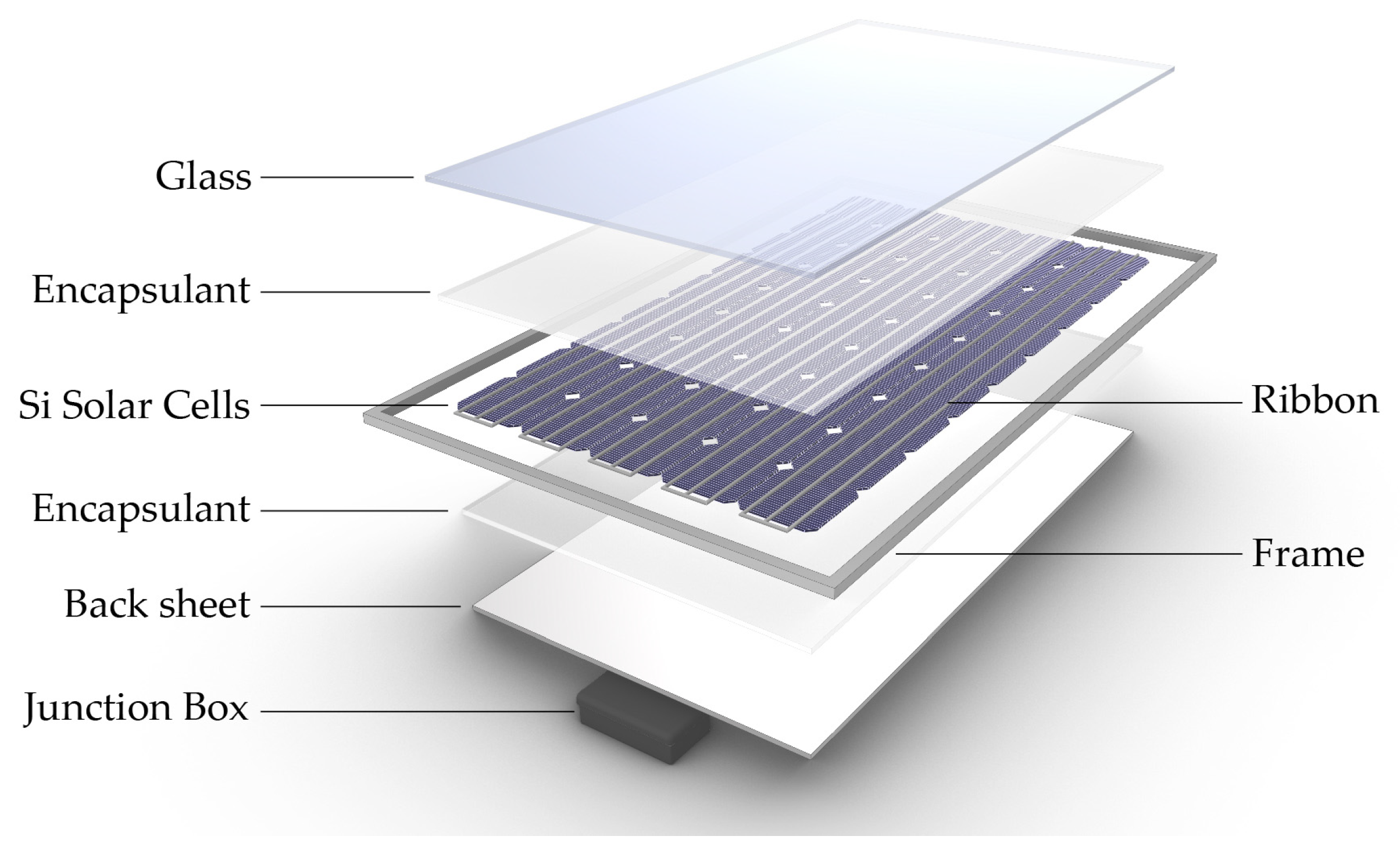
Figure 1 shows a typical silicon PV module that consists of glass, an encapsulant, silicon solar cell, a backsheet, a frame, and a junction box. In the past, 60-cell modules were commonly produced; however, 72-cell modules and 144-cell modules have only recently been manufactured using half-cut technology. In addition, modules with glass or transparent backsheets have been commercialized for producing bifacial solar modules. Table 1 lists the amounts of materials contained in the silicon PV module.
A low-iron glass with a thickness of approximately 3 mm is commonly used as the front glass to ensure high transparency and to protect PV modules from external damage. Recently, the use of 2.5 mm thick or less than 2 mm thick glass has increased [50]. In bifacial PV modules, glass is used as a backsheet alternative, allowing the generation of solar energy from both sides [51]. Antireflection coatings are applied to glass to form textured surfaces for reducing light reflection and increasing light absorption. This not only enhances the efficiency of the modules but also improves their aesthetics. With the anti-reflection coatings, the transparency of the glass improves to approximately 94.5%, which is approximately 3% higher than that of the uncoated glass. The use of antireflection coatings and textured surfaces has become standard practice in PV module manufacturing, and it has led to a higher energy output and a more attractive appearance [50]. Anti-soiling, anti-glare, color coating, and structuring treatments are applied based on the environment in which the module is used [52].
An encapsulant combines the components of a module and plays an essential role in ensuring its long-term stability. Ethylene-vinyl acetate (EVA) is commonly used for this purpose. However, during the operation of a solar module in the field, potential-induced degradation (PID) can occur when EVA is used. Acetic acid, which can be generated from EVA, can potentially corrode glass-cell interfaces and metal components; this can pose challenges for the recycling processes. To mitigate this issue, polyolefins are sometimes used as substitutes for EVA, and their use has been gradually increasing [50,53,54].
Si solar cells are typically based on n- or p-type Si wafers. These solar cells are electrically connected using ribbons containing lead [55]; however, there is an increasing trend toward the use of lead-free materials for ribbons in module production for reducing the amount of lead used. In addition, the use of electrically conductive adhesives (ECA) to connect the busbar of solar cells without using a ribbon is expected to increase gradually [50].
The backsheet in PV modules ensures the electrical safety inside the module and protects the internal electrical wires and junction box from moisture, dust, debris, and other external factors [56]. The backsheet is composed of a three-layer structure made of EVA or polyvinylidene fluoride (PVF) sandwiched between two layers of polyethylene terephthalate (PET) film [57]. White backsheets are commonly used in PV modules; however, black backsheets are also used depending on the usage environment and purpose of the module [58]. Transparent backsheets or glass are used in bifacial PV modules [53]. The aluminum frame protects the edges of the module from external impacts and facilitates the installation of the solar module. In general, silver is used; however, other colors can also be used depending on the situation [59]. The junction box connects the electricity generated from the solar cells of the module to the external environment through cables. In addition, bypass diodes in the junction box prevent hotspots from occurring when the module is not illuminated uniformly, such as in the presence of shadows [60].
3. Photovoltaic Module Recycling Processes
Mechanical, thermal, and chemical processes are used to separate and recycle the components of a PV module. The mechanical processes for recycling end-of-life silicon PV modules typically involve crushing and sorting. The modules are broken down into small pieces in the crushing process, and useful materials, such as glass, cells, and aluminum, are separated and processed for reuse in the sorting process. It is difficult to separate the components of a module using only mechanical methods, and therefore, thermal and chemical methods are often employed afterward. This approach is relatively simple and can rapidly process a large number of modules. Furthermore, this approach offers environmental benefits because it reduces the waste generated during the crushing and sorting processes. The components of the module are crushed, and therefore, they cannot be recovered without being broken. In addition, the fine particulate matter generated during crushing can contribute to environmental pollution [22,23,24,25,26,27,28,29,30,31,32,33].
Thermal processes are used to remove encapsulants after the mechanical process; they can also be used to recover the glass and silicon solar cells of a module without breaking them. However, thermal methods require considerable energy and produce significant amounts of harmful gases and byproducts during treatment. If the frame, junction box, and cable are removed from the module and the module is immediately subjected to thermal treatment, harmful gases, such as HF, may be generated because the backsheet contains fluorine. Thus, the backsheet is often removed before thermal treatment, and the process is subsequently performed [17,18,22,29,34,35,36,37,38,39,40,41].
Chemical processes such as the thermal method that has been described can also be utilized to remove the encapsulant after the mechanical method. Chemical methods can be used to recover intact module components; however, the reaction time required increases with an increase in the area of the module. Research is currently underway to solve this problem [42,43,44,45,46,47,48]. Another disadvantage of this process is the burden of additional environmental pollution generated by the treatment of used chemicals.
The three processes were compared in terms of processing speed, environmental impact, possibility of mass processing, and state of component recovery. The results indicate that the mechanical process is the fastest among all methods and realized a lower environmental impact than that of the other two. In addition, the thermal process offers the advantage of being able to handle large quantities of modules, and is the most effective method of recovering components in intact conditions after processing.
3.1. Mechanical Process
Granata et al. conducted research on the classification and crushing of PV modules using two methods. The first method involved the use of a two-blade rotor followed by thermal treatment; the second method involved the use of a two-blade rotor followed by hammer crushing. In the first method, roughly 70% of the resulting particles had a diameter greater than 8 mm and were joined together with EVA when crushed. Thermal treatment was carried out at 650 °C to eliminate EVA. Approximately 85% of the particles with diameters greater than 1 mm were recovered directly as glass, whereas only 10% were recovered with diameters below 1 mm. Silicon was mixed with glass for particles with diameter ranging between 0.08 and 1 mm; an additional process was necessary to recover them. In the second method, in which hammer crushing was used, the size distribution of the particles was similar to that of the first method. However, EVA was still present in particles with diameters greater than 5 mm. Si was successfully recovered from particles with diameters smaller than 0.08 mm. Compared to the first method, slightly more glass was recovered from the second method using hammer crushing [23].
Pagnanelli et al. increased the glass recovery rate through three consecutive crushing processes using a two-blade rotor. The resulting particles were sieved into five sub-fractions: 8, 5, 1 mm, 0.4 mm, and 0.08 mm. During the first crushing process, 70% of particles larger than 8 mm and approximately 20% of particles ranging from 1 mm to 5 mm were sieved. During the second crushing process, 50% of the particles that were larger than 8 mm, 20% of particles ranging from 1 to 5 mm, and 10% of particles ranging from 0.4 to 1 mm were sieved. After the last third crushing process, 40% of particles larger than 8 mm, 25% of particles ranging from 1 to 5 mm, 17% of particles ranging from 0.4 to 1 mm, and 10% of particles ranging from 0.08 to 0.4 mm were sieved out. Approximately 12 ± 6% of the total glass was recovered from the 0.4 to 1 mm particles. The three consecutive crushing processes had two benefits: (1) After crushing, only a coarse fraction required thermal treatment, reducing the amount of waste that needed to be treated in subsequent processes. Approximately 85% of the waste required thermal treatment after one crushing process, and after three crushing processes, only 62% required thermal treatment; (2) The glass recovery rate increased. After one crushing process, less than 10% of the total glass was recovered; however, after three crushing processes, approximately 17% was recovered. Next, particles larger than 1 mm, which accounted for about 65% of the total number of particles, were heated in a furnace at a heating rate of 10 °C/min up to 650 °C for 1 h. After thermal treatment, the weight loss was approximately 15%, which was almost identical to the general EVA content, indicating that EVA was removed completely from the particles. After sieving the particles, approximately 50% of particles ranging from 1 to 5 mm, 20% of particles ranging from 0.4 to 1 mm, and 10% of particles ranging from 0.08 to 0.4 mm were sieved. Approximately 66 ± 8% and 12 ± 6% of the total glass weight was recovered from particles ranging from 1 to 5 mm and 0.4 to 1 mm, respectively. A glass recovery rate of over 91% was achieved after three crushing processes and thermal treatments; this recovery rate is higher than that achieved in a previous study (85%). Three consecutive crushing processes, combined with a thermal treatment, can lead to higher glass recovery rates, and this can help reduce waste and promote sustainability [24].
La Mia Energia Scarl developed an on-site recycling method for PV modules using portable equipment. Initially, they cut the PV modules into 100 × 100 mm pieces using a cutting machine. These cut pieces were then processed using a hammer mill and sieved consecutively through 6 mm and 2 mm meshes. The resulting fragments were sorted into three categories based on size, and each category was recovered separately. The first category (ranging from 0.5 to 2 mm) contained plastic and copper. A rotating magnetic field was used to induce currents to recover copper, other metals, and plastics. The second category (ranging from 0.5 to 0.315 mm) contained relatively small silicon fragments mixed with glass. The third category (below 0.315 mm) contained relatively large amounts of silicon fragments mixed with glass. By using a rotating magnetic field, valuable materials, such as copper and silicon, could be efficiently recovered from PV modules onsite using portable equipment [25].
Yingli Solar utilized cryogenic methods to separate the PV modules. The modules were crushed and the resulting mixture was abraded at cryogenic temperatures. The mixture consisted of EVA, silicon, silver, and aluminum, which were separated using the electrostatic separation method. However, the separated Si has low purity and cannot be reprocessed into new wafers; thus, further research is required to address this issue [26].
NPC incorporated, Japan developed a method that uses a heated blade (hot knife) to separate the EVA between the glass and the cells. The heated blade (hot knife) is a 1 m long steel blade heated to 180–300 °C. This method can be used to recover intact glass and it only requires approximately 40–60 s per module. However, during the separation process, cells can break, and additional processing is required to separate them [27,28].
The Mitsubishi Materials Corporation developed a glass-scraping method that can process one module per minute. Toho Kasei scraped the backsheet instead of the glass and recovered the materials through additional chemical processes. In the Full Recovery End-of-Life Photovoltaic (FRELP) project in Europe, modules were heated to 90–120 °C using an IR heater; the glass was recovered using roller mills and high-frequency vibrating knives [29].
Li et al. proposed a mechanical treatment to remove and recycle the EVA layer from the PV module. Their approach employed a 1064 nm optical-fiber pulsed laser to irradiate the back EVA layer, followed by mechanical peeling. Initially, the backsheet of the module was removed, and then, the laser was applied through the back EVA layer to the interface between the cell and the back EVA. The metal electrode at the back of the cell absorbed the laser energy, leading to a rise in temperature at the cell/EVA interface, weakening the adhesion of EVA to the cell. The experiment demonstrated that an increase in the laser output density (P) and pulse repetition rate (PRR) enhanced the debonding effect. However, excessive P or PRR values can lead to significant damage to the cell and to the back of the EVA layer because of the significant rise in temperature at the cell/EVA interface. The thermal decomposition and charring of the EVA layer were also observed. Through experiments, Li et al. achieved a perfect debonding effect by controlling the laser using an optimized combination of P and PRR (P 2.1 MW/cm2 and PRR 50 kHz). Consequently, the back EVA layer was easily removed mechanically, and both the removed EVA and cells were recyclable and not damaged by laser treatment. This innovative approach for removing and recycling the EVA layer using laser-based mechanical treatment has a significant potential toward improving the sustainability and cost-effectiveness of the PV module industry [30].
Song et al. applied high-voltage fragmentation (HVF) as a mechanical treatment for decamping PV panels. Based on their experimental results, they claimed that HVF resulted in significantly less material wastage and improved crushing effects. When HVF is applied to PV panels, discharge channels are formed at the interfaces of the different layers because of the varying dynamic fracture strengths of the dielectrics that constitute the panel materials. These channels then expand radially and eventually exceed the tensile strength of the materials, fragmenting the constituent components of the layers. Based on this principle, HVF was used to investigate the distribution of Cu, Al, Pb, Ag, and Sn at various particle sizes and to explore the energy consumption and mechanism of the HVF for the PV panel crushing effects. During the experiment, an upper electrode in the form of a 5.7 mm diameter column was used along with a grounding electrode equipped with a 1 mm hole. The experiment demonstrated that the average particle size of the crushed PV panels decreased with an increase in the pulse number and voltage amplitude. The optimal conditions for HVF in terms of energy savings were determined to be 192.99 J/g following 300 pulses at 160 kV. The PV panels were crushed into particles with an average size of 4.1 mm. The experimental results showed that, with the exception of Al, a relatively low proportion of metals was found in particles ranging from 1 to 5 mm. Over 95% of Cu and 96% of Ag were detected in particles smaller than 1 mm, whereas 85% of Al was detected in particles ranging from 0.25 to 2 mm. In particles smaller than 0.5 mm, 85% of Pb and 87% of Sn were detected; this method is environmentally friendly because it does not generate additional pollution, unlike the thermal and chemical treatment methods. The crushed particles are concentrated in specific size fractions convenient for metal recovery, and their energy consumption is relatively low, which makes them an economically attractive method. However, HVF has the disadvantage of requiring strict conditions such as the pulse rise time of less than 500 ns, a high-voltage volume of 100 kV or more, and a repetition pulse frequency [31].
Nevala et al. proposed a mechanical treatment method that employs electrohydraulic fragmentation (EHF), which is a type of high-voltage pulse crushing, to achieve a higher separation efficiency. The EHF process crushes various materials that constitute the PV modules using mechanical shock waves generated in a fluid medium. EHF generates short, powerful shockwave pulses through an electrohydraulic mechanism between electrodes in a fluid, fracturing weak points in the interface between different materials. In the experiments, shockwave impulses of 600 J were used at rates of 300 and 500 pulses/s. The resulting crushed particles were collected and heated in a muffle furnace at 60 °C for 24 h before being sieved into six categories: smaller than 0.25 mm, from 0.25 to 0.5 mm, from 0.5 to 1 mm, from 1 to 2 mm, from 2 to 4 mm, and larger than 4 mm. The results of the EHF experiments demonstrated that compositions of 99% Cu, 60% Ag, and 80% Pb, Sn, and Al could be obtained in crushed particles larger than 4 mm when using a rate of 300 pulses per second. However, the rate of 500 pulses per second resulted in a lower metal content in the crushed particles that were larger than 4 mm, with compositions of 98% Cu, 40% Ag, and 60% Pb, Sn, and Al. Furthermore, after EHF, 99% high-purity Si could be extracted from particles larger than 0.5 mm and smaller than 2 mm. This method offers the advantage of facilitating subsequent processing and extraction compared to conventional crushing methods; furthermore, it can produce significantly higher-purity Si. EHF is a promising mechanical treatment method that can increase separation efficiency during the decomposition of PV modules. The utilization of shock waves generated in a fluid medium using an electrohydraulic mechanism highlights the superiority of this method over conventional crushing methods. EHF provides a high separation efficiency for various metals and it produces high-purity Si, which is beneficial for subsequent processing and extraction [32].
Akimoto et al. developed a high-voltage pulse crushing technique that combines sieving and dense-medium separation for mechanical treatment to separate the materials in the PV panels. The experiments involved two stages: primary and secondary crushing. In the primary crushing stage, a high-voltage pulse crushing technique using an impact wave transmitted to the Al electrode and Si substrate was employed for separating the glass and backsheet layers. Experiments with discharge voltages of 90, 110, 130, and 180 kV and 10 or 20 pulses confirmed that the glass and backsheet layers could be separated without damaging the cell at 110 kV and 20 pulses. In the secondary crushing stage, high-voltage pulse crushing was applied to the glass layer to separate the EVA and glass and to the backsheet layer to separate the bus bar. Experiments with discharge voltages of 90, 130, and 180 kV and 50, 100, 150, 200, and 250 pulses showed that EVA and glass could be separated without destruction at 90 kV with 250 pulses. The crushed particles obtained from the secondary crushing stage were sieved, which resulted in a small amount of glass, including Si powder in the size range of 45–850 μm. The glass containing the Si powder was refined by dense-medium separation at a specific gravity of 2.4. Metals such as Cu, Sn, and Pb were recovered in the range of 1.0–8.0 mm, while Ag was recovered in sizes below 20 μm, as well as in the ranges 2.0–4.0 mm and 4.0–8.0 mm. These results demonstrated the effectiveness of the high-voltage pulse crushing technique for separating the various materials in the PV panels [33].
Table 2 provides a concise overview of the mechanical processes.
3.2. Thermal Process
Lee et al. developed a method for recovering intact Si wafers via thermal treatment. To achieve this, the modules were pre-treated using three methods: glass cracking, EVA patterning, or a combination of both. The pre-treated modules were subjected to heat treatment at 200, 250, and 300 °C, and the results were examined. EL imaging confirmed breakage in the cells, and the thermogravimetric analysis (TGA) showed thermal decomposition in the range of 25–550 °C. The expansion behavior of EVA was confirmed through the expansion mode of thermal mechanical analysis (TMA). During the experiment, the cells underwent significant changes when exposed to different temperatures. Exposure to a temperature of 300 °C resulted in the cells breaking and becoming carbonized, appearing black with numerous bubbles present. However, the cells did not break when exposed to a temperature of 250 °C; however, they underwent carbonization, resulting in a brown coloration. TGA was used to confirm the stages of EVA decomposition; the TGA results showed that EVA decomposition occurs in two stages, with the first stage occurring in the temperature range of 240–300 °C. This stage was influenced by the round cracks that occurred in the cells. The round cracks were formed at temperatures above 240 °C because of the acetic acid generated during this process (the acetic acid is subsequently removed at temperatures near 370 °C). The second stage of decomposition occurs in the temperature range of 420–450 °C, and it is attributed to combustion reactions. Finally, EVA was completely combusted at 520 °C. The pressure generated by trapped gases ultimately leads to cell breakage. The expansion behavior of the laminated EVA was confirmed using TMA, which revealed that EVA expands up to 79 °C as it transitions from its crystalline state to the amorphous state. Then, it contracts up to 130 °C because of the cross-linking reactions that cure EVA. Acetic acid is generated and subsequently removed, and EVA undergoes further expansion and contraction within the temperature range of 130–270 °C during carbonization, with the EVA contracting up to a temperature of 370 °C because of the evaporation of acetic acid. EVA was combusted at temperatures above 420 °C. Various methods were applied to recover intact Si wafers from modules, and the results were examined. Finally, intact Si wafers were recovered from modules in which both glass cracking and EVA patterning were applied. When only glass cracking was applied, round cracks appeared because of the acetic acid generated during the process. When only EVA patterning was applied, cracks occurred following the crystal orientation because of the expansion and contraction of the EVA material [34].
Park et al. introduced a jig to prevent damage to the cells. The PV modules were subjected to tests with and without the use of a specifically designed jig, which featured 5 mm wide grooves spaced at 5 mm intervals to facilitate the release of gas generated during the annealing process. The annealing temperature and ramp-up rate were analyzed. Two sample groups were established. The first group had a fixed annealing temperature of 480 °C tested at five different ramp-up rates, 5, 10, 15, 20, and 30 °C/min. The second group had a fixed ramp-up rate of 15 °C/min tested with four different annealing temperatures, 350, 400, 450, and 480 °C. In the first group, the cells remained undamaged and could be recovered when the jig was used in conjunction with a ramp-up rate of 15 °C/min. Conversely, cells without jigs were damaged under all conditions. In the second group, the cells remained undamaged and could be recovered when using the jig with an annealing temperature of 480 °C; however, cells without the jig were found to be damaged under all conditions. The complete separation of the EVA and backsheet was not observed at temperatures below 450 °C. During the annealing process, gas accumulates in the EVA layer between the cells and the backsheet and between the cells and the glass. Among these, the gas that accumulates between the cells and the glass has a more significant impact on cell damage because the backsheet is relatively more effective at releasing gas than glass. The accumulation of gas leads to stress in the cells, and cell damage occurs when this stress reaches a critical level. The jig used in this study prevented excessive stress on the cells; the gas generated during annealing was released through the grooves in the jig, resulting in the recovery of undamaged cells. These findings emphasize the importance of using a specially designed jig for preventing cell damage during the annealing of PV modules [35].
Wang et al. developed a two-step heating profile to recover intact glass and prevent cracks caused by the expansion of the backsheet and EVA. In the first step, the module was heated to 330 °C for 30 min to separate the backsheet from the EVA. Although the EVA did not separate because of the decomposition of the backsheet temperature range of 260 °C to 300 °C, the backsheet was removed successfully. In the second step, the module was heated to 400 °C for 120 min to burn off the EVA and backsheet. The two-step process prevented the deformation of the backsheet and EVA, and this in turn prevented glass cracks and allowed the recovery of intact glass [36].
Frisson et al. investigated two pyrolysis methods using a conveyor belt furnace and a fluidized bed reactor. In a conveyor belt furnace, pyrolysis was conducted at 450 °C in both air and nitrogen atmospheres. The air atmosphere resulted in an exothermic reaction on the silicon surface, causing the cells to break; however, this exothermic reaction was avoided in a nitrogen atmosphere, and a recovery yield of over 80% was achieved. In the fluidized bed reactor, pyrolysis was conducted at 450 °C for 45 min using very fine sand as the bed material. The sand particles were fluidized at a velocity of 1 cm/s for a particle diameter of 100 μm, and modules were placed in a netting envelope. A recovery yield of over 80% was obtained, and almost 100% of the glass was recovered from the modules [37].
Doni and Dughiero utilized an electrothermal heating method instead of a conventional furnace for separating the components of the PV modules. They employed an RF power generator and positioned nonmagnetic flat electrodes above and below the module to generate a uniform transverse RF electric field. The lower electrode was grounded, and the upper electrode was connected to apply the RF voltage. They found that glass fragments separated easily from the EVA, and the remaining parts from which the glass had been removed could be recovered for other recycled materials through post-treatment processes. The recovered glass could be recycled directly [38].
The Kitakyushu Foundation for the Advancement of Industry, Science, and Technology (FAIS) utilized a milling machine to remove the backsheet, preheated the module at 350 °C, and then combusted it up to 500 °C before cooling it down to 250 °C. The heat generated by the combustion of the EVA in the furnace was reused. The Chinese Research Academy of Environmental Sciences (CRAES) and the Institute of Electrical Engineering, Chinese Academy of Science (IEE CAS) utilized a tube furnace for performing a two-step thermal process at 250–300 °C and 500–550 °C with the environment inside the tube alternating between oxygen and nitrogen [29].
Fiandra et al. proposed an advanced thermal treatment method for the minimizing hazardous gas emissions that occur during the degradation of the backsheet in PV waste. In this method, a PV waste sample was inserted into a quartz sample holder and placed in a tube furnace, where it was heated at a rate of 450 °C/h to 200 °C in the absence of gas flow. The sample was held at 200 °C for 30 min, and then cooled to room temperature. This combustion process was designed to remove the polymer layer from the backsheet, which could be easily removed manually from the initial PV sample. Afterward, air was supplied to the reactor at a flow rate of 24 L/h, and EVA was removed by heating at a rate of 450 °C/h to 500 °C for 1 h. This method proved effective in removing hydrofluoric acid and fluorinated organic compounds generated during the decomposition of the backsheet [52]. In a follow-up study, Fiandra et al. aimed to reduce the emission of pollutants and decrease the mass and energy consumption of PV waste sent for thermal treatment using a milling machine to remove the backsheet layer. To prevent the cracking of the silicon wafer, the module was pretreated with glass cracking and EVA patterning before thermal treatment. The backsheet layer was removed using a vacuum-suctioned and panel-fixed machine with an 18 mm tip diameter at 18,000 rpm and a cooling system that used air. The rest of the backsheet was removed by chipping the backsheet–EVA interface. The experimental results showed that the mechanical removal of the backsheet from the PV module removed HF, COF2, and fluorinated organic compounds, which are hazardous to human health and the environment. In addition, the trend of carbon in gaseous products, such as CO, CO2, and volatile organic compounds (VOCs), generated during EVA thermal treatment at variable temperatures was investigated. The carbon combustion efficiency was the highest at 500 °C and 600 °C. The results showed a reduction in VOCs under oxidation conditions because carbonaceous byproducts were oxidized to CO2 under these conditions. Therefore, EVA thermal treatment at 500 °C under N2 flow was conducted to reduce energy consumption and VOC emissions. This approach successfully reduced the VOC emissions generated during the EVA thermal treatment [40].
Riech et al. conducted experiments to realize the complete combustion of EVA through thermal treatment that uses a combination of time (50–60 min) and temperature (400–650 °C). The results showed that the complete combustion of EVA was achieved in a sample treated at 550 °C for 60 min. There were no significant differences in the results when the treatment time or temperature were increased, except for an increase in energy consumption. In the next experiment, they investigated the time and temperature required for the complete combustion of EVA based on energy consumption. The results showed that EVA could be completely combusted with the lowest energy consumption when treated at 650 °C for 30 min [41].
Table 3 provides a concise overview of the thermal processes.
3.3. Chemical Process
Doi et al. investigated the effects of 12 different solvents, including lacquer thinner, acetone, toluene, petroleum benzene, ethanol, isopropanol, methyl ethyl ketone, methyl isobutyl ketone, tetrahydrofuran, ethylene glycol, trichloroethylene, and glycerin, on the separation of modules by observing the changes in EVA. The EVA was categorized based on crosslinking, and the solvents were tested at room temperature and at 80 °C. Trichloroethylene was found to cause the most significant change in EVA under all conditions; it was, therefore, selected as the solvent for the experiment. A one-cell module with a glass/EVA/cell/EVA/aluminum foil structure was created to confirm the separation of the module. However, when the module was initially immersed in trichloroethylene at room temperature, the cells were damaged after a few days due to EVA swelling. To address this issue, glass was added to the back of the module for mechanical pressure, and the experiment was conducted at room temperature and at 80 °C. An intact solar cell was recovered under the condition of 80 °C with the addition of one glass to the back, which took approximately 7–10 days. In addition, the same experiment was conducted using o-dichlorobenzene as the solvent, and an intact solar cell was recovered without additional glass at 120 °C after one week [42].
Kang et al. conducted experiments to confirm the dissolution of EVA in 10 different solvents: 2-propanol, 4-methyl-2-pentanone, petroleum benzene, tetrahydrofuran, trichloroethylene, toluene, o-dichlorobenzene, glycerin, acetone, and ethyl alcohol. They confirmed that tetrahydrofuran, o-dichlorobenzene, and toluene can be used for this purpose. Toluene was selected because of its low cost and high stability; it took approximately two days for the glass to separate from the module at 90 °C. The EVA laminated on the module comprised crosslinked and non-crosslinked parts. EVA dissolved in the non-crosslinked part when organic solvents were applied. The solvents swell the cross-linked part of EVA, which weakens its binding force and leads to its dissolution and swelling [43].
Kim et al. conducted experiments on four different solvents (toluene, trichloroethylene, o-dichlorobenzene, and benzene) to investigate their ability to dissolve EVA at various concentrations and temperatures with the addition of ultrasonic treatment. Ethyl alcohol was used to adjust the alcohol concentration. They confirmed that solubility was greater at 3 M than at 1 M and that solubility increased with the increasing temperature. Under the conditions of 3 M toluene, 70 °C, 60 min, and 450 W ultrasonic treatment, EVA was dissolved completely; however, the cells were damaged because of EVA swelling. Increasing the ultrasonic intensity at higher temperatures resulted in a more effective dissolution. However, in toluene, there was little difference in the degree of dissolution when only the ultrasonic intensity was changed under the same conditions. This suggests that toluene was more influenced by the concentration. Under 3 M o-dichlorobenzene, 70 °C, 60 min, and 900 W conditions, EVA was dissolved completely without damaging the solar cell. However, other solvents can cause cell damage. Finally, under 3 M o-dichlorobenzene, 70 °C, 30 min, and 900 W conditions, EVA was dissolved completely without damaging the cell, and the cell was recovered [44].
Azeumo et al. conducted experiments to determine the optimal conditions for dissolving EVA using water, toluene, xylene, 2,4-trimethylpentane, n-heptane, and N,N-dimethylformamide. The variables used were solvent residence time, temperature, and ultrasonic treatment. The effect of preheating the module at 200 °C before immersing it in the solution was also investigated. After preheating, the module was immersed in each solvent at its boiling point and subjected to an ultrasonic treatment for 2 h. The results indicated that water, 2,4-trimethylpentane, n-heptane, and N,N-dimethylformamide did not dissolve EVA. However, xylene and toluene dissolved more than 90% of the EVA. Toluene was then used under various conditions, and it was found that EVA dissolved by more than 95% with ultrasonic treatment at 60 °C for 50 min, while it detached completely without ultrasonic treatment at 110 °C for 30 min. Preheating the module did not significantly affect the results [45].
Tembo et al. used hexane as a solvent for the chemical treatment to dissolve EVA and recover PV cells. The initial results showed a separation rate of 66% for the hexane-based system after 24 h at 25 °C. Using temperature as a variable, the highest separation rate of 79.7% was observed at 70 °C, slightly above the boiling point of hexane at 66 °C. Hexane at 70 °C showed greater separation rates compared to those at 80 °C and 90 °C. The separation rates were measured at different hexane concentrations, including 1, 2, 5 M, and pure hexane. Pure hexane exhibits the highest recovery rate. The effect of ultrasonic treatment at various concentrations at 70 °C was also investigated. The sample was treated with ultrasonic waves for 15 min and then dissolved in pure hexane at 70 °C. The experiment showed that the sample treated with ultrasonic waves for 15 min and chemically treated with pure hexane at 70 °C had the highest separation rate of 92.4% [46].
Xu et al. devised a solvothermal swelling with thermal decomposition (SSTD) method that allowed the recovery of intact solar cells during heat treatment. However, during the thermal decomposition process, gases were produced from the ethylene vinyl acetate (EVA) located between the glass and the cell; these gases were trapped by the glass, ultimately causing damage to the cell. To address this issue, channels were created to discharge the gas generated horizontally during pretreatment. The pretreatment conditions were optimized by testing various temperatures, processing times, and solution conditions. Ultimately, a mixture of 0.2 M toluene and 0.2 M ethanol was used for the pre-treatment, exposing the module to organic vapors at 190 °C for 2 h, followed by thermal treatment in a 500 °C furnace to remove the residual EVA and backsheet and obtain intact solar cells. The recovery rate of the intact solar cells was 86.11% for a commercial 36-cell PV module. The recovered cells were obtained in wafer form via chemical etching, and their durability was confirmed to be comparable to that of the new wafers [47].
Table 4 provides a concise overview of the chemical processes.
4. Silicon Photovoltaic Module Designs for Recycling
PV modules require a long-term stability of approximately 30 years, and manufacturers produce modules by increasing their durability to achieve this. However, these efforts have resulted in difficulties in separating the PV module components. The cost of recycling PV modules is higher than that of landfill [13]. Therefore, there is an urgent need to develop methods that can effectively recycle PV modules both economically and environmentally. It is important to not only find ways to recycle end-of-life PV modules but also to consider their recyclability during the manufacturing process. Thus far, several attempts have been made to design modules while considering their recyclability [61,62,63,64].
4.1. Nonadhesive Sheet
Doi et al. proposed a “double encapsulation module (DEM)” structure in which nonadhesive sheets were placed between the EVA and the solar cells in the standard module structure. The layers were cut on the backsheet using an ultrasonic cutter, and 91% of the solar cells were recovered intact. In addition, long-term stability tests (JIS C 8917-Appendix 2, 11 [65]) were conducted on the modules with the new structure; the results demonstrated their good durability [61].
However, this design’s weakness is the reduced power consumption, which can be attributed to the addition of a nonadhesive sheet. To address this issue, Li et al. proposed a “DEM with optical coupler (DEMOC)” structure that adds an optical coupler (OC) between the front nonadhesive sheet and the solar cells [62]. Although the power was not directly compared because of the differences in module design, it was predicted that the power would improve based on the changes in Isc before and after encapsulation for each module structure. This structure improved reflectance compared to that of the DEM module, and it showed characteristics similar to those of the standard module. It became relatively difficult to separate the solar cells because the OC was applied. First, the backsheet was cut, and then the interface between the nonadhesive sheet and OC was separated from the nonadhesive sheet/OC/solar cell structure using a thin wire. The separated OC/solar cell structure was further separated to recover the solar cells; 50% of the solar cells were recovered successfully.
4.2. Module Structure without Encapsulant
Apollon Solar developed a module called the “New Industrial Solar Cell Encapsulation (NICE)” module; it does not have an encapsulant and the edges are sealed using poly-isobutylene (PIB). Furthermore, PIB is used as an adhesive to attach solar cells and ribbons. The module uses glass or metal foil on the back and has an edge-sealing integrated external connector. It passes the damp heat and thermocycle tests in IEC 61215 [66]. To separate the components of this module, a PIB/silicone edge seal was cut using thermocutters or standard cutters combined with a hot air gun [64,67,68,69].
Fraunhofer ISE proposed a gas-filled edge sealing structure called the “TPedge” module [63,70,71,72]. Silicone and a thermoplastic spacer (TPS) were used for edge sealing, and air was filled between the front and back glass. The front glass was coated with anti-reflection coating (ARC) on both sides to minimize reflection losses. To attach the solar cells to the back glass, a UV-cured acrylate adhesive was used to provide additional mechanical stability. Compared to the standard modules, the TPedge module had a material cost that was approximately 15.3% lower but it has more production steps. The production time is shorter and it is less than 1 min [63]. The module underwent IEC 61215/61730 [73] testing and passed 400 thermal cycles, damp heat, a potential-induced degradation (PID) test, hot-spot endurance, and UV stability tests. In addition, it was subjected to mechanical load testing up to 5400 Pa, and it showed no degradation after the hail impact testing. Furthermore, after 14 months of outdoor exposure, there was little change in the power. However, the cell-to-module (CTM) loss was higher than that of the standard module because of the small CTM gain by coupling [71].
5. Conclusions
With an increase in the installation capacity of photovoltaic modules globally, effective recycling and reuse strategies for end-of-life modules are crucial in minimizing environmental impacts and reducing production costs. In recent years, significant progress has been made in developing innovative recycling methods for PV modules, including mechanical, thermal, and chemical processes. However, each process has advantages and limitations, and a combination of different processes may be necessary for effective and efficient recycling. Furthermore, the efficiency and cost-effectiveness of recycling PV modules can also be improved. It is essential to continue research and development in this field to ensure that the growing number of waste photovoltaic modules will not pose a significant environmental challenge in the future.
This review summarized the existing research on the separation processes of silicon PV modules for recycling and identified future research directions. A considerable amount of research on separation processes focused on recovering materials from modules that require remanufacturing for recycling purposes.
The energy required to produce Si wafers accounts for a significant portion of the energy used to produce PV modules [62,74]. In addition, recycling glass can reduce energy consumption by approximately 40% compared to the energy consumption that results from the production of new glass [75]. Therefore, more research studies are required to recover intact glass and solar cells from end-of-life PV modules. Various studies have focused on the recovery of intact Si solar cells by chemical etching to obtain Si wafers. If efficient methods for recovering solar cells in their intact state can be improved, various studies related to the recycling of Si solar cells can be effectively combined. This would lead to the development of recycling processes for end-of-life solar modules in terms of energy consumption and economy.
In addition to developing methods for recycling modules, efforts have been made to change module designs and materials to make them more recyclable. The validation of their long-term stability is necessary when the structure and materials change. However, if its durability is validated and it is cost-effective with mass-production capability, it can become a new standard for PV modules.
Author Contributions
J.K.: Conceptualization, formal analysis, investigation, data curation, writing—original draft preparation, writing—review and editing, and visualization. K.K.: Conceptualization, formal analysis, investigation, data curation, writing—original draft preparation, writing—review and editing, and visualization. J.W.S.: investigation and data curation. H.J.: Formal analysis and data curation. H.-S.L.: validation and supervision. D.K.: validation and supervision. Y.K.: Conceptualization, validation, supervision, project administration, writing—review, and editing. All authors have read and agreed to the published version of the manuscript.
Funding
This research was supported by BK21 FOUR Program through the National Research Foundation of Korea (NRF) funded by the Ministry of Education (4199990514635), and this work was also supported by the National Research Foundation of Korea (NRF) grant funded by the Korea government (MSIT). (No. 2022M3J7A1066428).
Data Availability Statement
Data sharing not applicable.
Conflicts of Interest
The authors declare no conflict of interest.
Nomenclature
| PV | Photovoltaic |
| IEA-PVPS | International Energy Agency Photovoltaic Power Systems Program |
| IRENA | International Renewable Energy Agency |
| EVA | Ethylene Vinyl Acetate |
| PID | Potential-Induced Degradation |
| ECA | Electrically Conductive Adhesive |
| PVF | Polyvinyl Fluoride |
| PET | Polyethylene Terephthalate |
| FRELP | Full Recovery End-of-Life Photovoltaic |
| P | Laser Output Density |
| PRR | Pulse Repetition Rate |
| HVF | High-Voltage Fragmentation |
| EHF | Electro-Hydraulic Fragmentation |
| TGA | Thermogravimetric Analysis |
| TMA | Thermal Mechanical Analysis |
| RF | Radiofrequency |
| FAIS | Kitakyushu Foundation for the Advancement of Industry, Science and Technology |
| CRAES | The Chinese Research Academy of Environmental Sciences |
| IEE CAS | Institute of Electrical Engineering, Chinese Academy of Science |
| EoL | End of Life |
| VOC | Volatile Organic Compound |
| SSTD | Solvothermal Swelling with Thermal Decomposition |
| DEM | Double Encapsulation Module |
| DEMOC | Double Encapsulation Module with Optical Coupler |
| OC | Optical Coupler |
| NICE | New Industrial Solar Cell Encapsulation |
| PIB | Poly-isobutylene |
| TPS | Thermoplastic Spacer |
| ARC | Anti-Reflection Coating |
| CTM | Cell-to-Module |
References
- Chowdhury, M.S.; Rahman, K.S.; Chowdhury, T.; Nuthammachot, N.; Techato, K.; Akhtaruzzaman, M.; Tiong, S.K.; Sopian, K.; Amin, N. An overview of solar photovoltaic panels’ end-of-life material recycling. Energy Strategy Rev. 2020, 27, 100431. [Google Scholar] [CrossRef]
- Xu, Y.; Li, J.; Tan, Q.; Peters, A.L.; Yang, C. Global status of recycling waste solar panels: A review. Waste Manag. 2018, 75, 450–458. [Google Scholar] [CrossRef] [PubMed]
- IEA-PVPS. Snapshot of Global PV Markets 2023. Available online: https://iea-pvps.org/snapshot-reports/snapshot-2023/ (accessed on 21 April 2023).
- Fthenakis, V.M.; Kim, H.C.; Alsema, E. Emissions from photovoltaic life cycles. Environ. Sci. Technol. 2008, 42, 2168–2174. [Google Scholar] [CrossRef] [Green Version]
- Venkatachary, S.K.; Samikannu, R.; Murugesan, S.; Dasari, N.R.; Subramaniyam, R.U. Economics and impact of recycling solar waste materials on the environment and health care. Environ. Technol. Innov. 2020, 20, 101130. [Google Scholar] [CrossRef]
- Tao, M.; Fthenakis, V.; Ebin, B.; Steenari, B.-M.; Butler, E.; Sinha, P.; Corkish, R.; Wambach, K.; Simon, E.S. Major challenges and opportunities in silicon solar module recycling. Prog. Photovolt. Res. Appl. 2020, 28, 1077–1088. [Google Scholar] [CrossRef]
- Aman, M.; Solangi, K.; Hossain, M.; Badarudin, A.; Jasmon, G.; Mokhlis, H.; Bakar, A.; Kazi, S. A review of Safety, Health and Environmental (SHE) issues of solar energy system. Renew. Sustain. Energy Rev. 2015, 41, 1190–1204. [Google Scholar] [CrossRef]
- Latunussa, C.E.L.; Ardente, F.; Blengini, G.A.; Mancini, L. Life Cycle Assessment of an innovative recycling process for crystalline silicon photovoltaic panels. Sol. Energy Mater. Sol. Cells 2016, 156, 101–111. [Google Scholar] [CrossRef]
- Duflou, J.R.; Peeters, J.R.; Altamirano, D.; Bracquene, E.; Dewulf, W. Demanufacturing photovoltaic panels: Comparison of end-of-life treatment strategies for improved resource recovery. Cirp Ann.-Manuf. Technol. 2018, 67, 29–32. [Google Scholar] [CrossRef]
- Parida, B.; Iniyan, S.; Goic, R. A review of solar photovoltaic technologies. Renew. Sustain. Energy Rev. 2011, 15, 1625–1636. [Google Scholar] [CrossRef]
- Goe, M.; Gaustad, G. Identifying critical materials for photovoltaics in the US: A multi-metric approach. Appl. Energy 2014, 123, 387–396. [Google Scholar] [CrossRef]
- IRENA; IEA-PVPS. End-of-Life Management: Solar Photovoltaic Panels; Technical Report; IRENA: Masdar City, Abu Dhabi; IEA-PVPS: Bern, Switzerland, 2016; Available online: https://www.irena.org/publications/2016/Jun/End-of-life-management-Solar-Photovoltaic-Panels (accessed on 21 April 2023).
- Deng, R.; Chang, N.L.; Ouyang, Z.; Chong, C.M. A techno-economic review of silicon photovoltaic module recycling. Renew. Sustain. Energy. Rev. 2019, 109, 532–550. [Google Scholar] [CrossRef]
- Huang, B.; Zhao, J.; Chai, J.; Xue, B.; Zhao, F.; Wang, X. Environmental influence assessment of China’s multi-crystalline silicon (multi-Si) photovoltaic modules considering recycling process. Sol. Energy 2017, 143, 132–141. [Google Scholar] [CrossRef]
- Hernandez-Lopez, D.A.; Rasikh, T.; El Mekaoui, A.; Bassam, A.; Vega De Lille, M.; Ricalde, L.J.; Riech, I. Does recycling solar panels make this renewable resource sustainable? Evidence supported by environmental, economic, and social dimensions. Sustain. Cities Soc. 2022, 77, 103539. [Google Scholar] [CrossRef]
- Cui, H.; Heath, G.; Remo, T.; Ravikumar, D.; Silverman, T.; Deceglie, M.; Kempe, M.; Engel-Cox, J. Technoeconomic Analysis of High-Value, Crystalline Silicon Photovoltaic Module Recycling Processes. Sol. Energy Mater. Sol. Cells 2022, 238, 111592. [Google Scholar] [CrossRef]
- Theocharis, M.; Pavlopoulos, C.; Kousi, P.; Hatzikioseyian, A.; Zarkadas, I.; Tsakiridis, P.E.; Remoundaki, E.; Zoumboulakis, L.; Lyberatos, G. An Integrated Thermal and Hydrometallurgical Process for the Recovery of Silicon and Silver from End-of-Life Crystalline Si Photovoltaic Panels. Waste Biomass-Valoriz. 2022, 13, 4027–4041. [Google Scholar] [CrossRef]
- Shin, J.; Park, J.; Park, N. A method to recycle silicon wafer from end-of-life photovoltaic module and solar panels by using recycled silicon wafers. Sol. Energy Mater. Sol. Cells 2017, 162, 1–6. [Google Scholar] [CrossRef]
- Vellini, M.; Gambini, M.; Prattella, V. Environmental impacts of PV technology throughout the life cycle: Importance of the end-of-life management for Si-panels and CdTe-panels. Energy 2011, 138, 1099–1111. [Google Scholar] [CrossRef]
- McDonald, N.; Pearce, J. Producer responsibility and recycling solar photovoltaic modules. Energy Policy 2010, 38, 7041–7047. [Google Scholar] [CrossRef] [Green Version]
- Heath, G.A.; Silverman, T.J.; Kempe, M.; Deceglie, M.; Ravikumar, D.; Remo, T.; Cui, H.; Sinha, P.; Libby, C.; Shaw, S.; et al. Research and development priorities for silicon photovoltaic module recycling to support a circular economy. Nat. Energy 2020, 5, 502–510. [Google Scholar] [CrossRef]
- Jia, Z.; Fang, L. Review of Solar Photovoltaic System Recycling Technologies and Regulations in China. In Proceedings of the 2016 International Conference on Power Engineering & Energy, Environment, Singapore, 18–19 January 2016. [Google Scholar]
- Granata, G.; Pagnanelli, F.; Moscardini, E.; Havlik, T.; Toro, L. Recycling of photovoltaic panels by physical operation. Sol. Energy Mater. Sol. Cells 2014, 123, 239–248. [Google Scholar] [CrossRef]
- Pagnanelli, F.; Moscardini, E.; Granata, G.; Atia, T.A.; Altimari, P.; Havlik, T.; Toto, L. Physical and chemical treatment of end of life panels: An integrated automatic approach viable for different photovoltaic technologies. Waste Manag. 2017, 59, 422–431. [Google Scholar] [CrossRef] [PubMed]
- LA MIA ENERGIA Scarl. PV-MOREDE PhotoVoltaic Panels Mobile Recycling Device Deliverable D3.3 Second PV-Morede Device Manufactured. Available online: http://www.pvmorede.it/public/D%203.3%20SECOND%20PVMOREDE%20DEVICE%20MANUFACTURED.pdf (accessed on 21 April 2023).
- Zhang, J.; Lv, F.; Ma, L.Y.; Yang, L.J. The status and trends of crystalline silicon PV module recycling treatment methods in Europe and China. Adv. Mater. Res. 2013, 724–725, 200–204. [Google Scholar] [CrossRef]
- Japanese Companies Work on Ways to Recycle a Mountain of Solar Panels. Nikkei Asia. Available online: https://asia.nikkei.com/magazine/20161117-INCOMING/Tech-Science/Japanese-companies-work-on-ways-to-recycle-a-mountain-of-solar-panels (accessed on 21 April 2023).
- Solar Panel Recycling Service. Available online: www.npcgroup.net/eng/solarpower/reuse-recycle/recycle-service (accessed on 21 April 2023).
- IEA-PVPS. End-of-Life Management of Photovoltaic Panels: Trends in PV Module Recycling Technologies. Available online: https://iea-pvps.org/key-topics/end-of-life-management-of-photovoltaic-panels-trends-in-pv-module-recycling-technologies-by-task-12/ (accessed on 21 April 2023).
- Li, X.; Liu, H.; You, J.; Diao, H.; Zhao, L.; Wang, W. Back EVA recycling from c-Si photovoltaic module without damaging solar cell via laser irradiation followed by peeling. Waste Manag. 2022, 137, 312–318. [Google Scholar] [CrossRef] [PubMed]
- Song, B.-P.; Zhang, M.-Y.; Fan, Y.; Jiang, L.; Kang, J.; Gou, T.-T.; Zhang, C.-L.; Yang, N.; Zhang, G.-J.; Zhou, X. Recycling experimental investigation on end of life photovoltaic panels by application of high voltage fragmentation. Waste Manag. 2020, 101, 180–187. [Google Scholar] [CrossRef] [PubMed]
- Nevala, S.-M.; Hamuyuni, J.; Junnila, T.; Sirviö, T.; Eisert, S.; Wilson, B.P.; Serna-Guerrero, R.; Lundström, M. Electro-hydraulic fragmentation vs conventional crushing of photovoltaic panels–Impact on recycling. Waste Manag. 2019, 87, 43–50. [Google Scholar] [CrossRef]
- Akimoto, Y.; Iizuka, A.; Shibata, E. High-voltage pulse crushing and physical separation of polycrystalline silicon photovoltaic panels. Miner. Eng. 2018, 125, 1–9. [Google Scholar] [CrossRef]
- Lee, J.K.; Lee, J.S.; Ahn, Y.S.; Kang, G.H.; Song, H.E.; Kang, M.G.; Kim, Y.H.; Cho, C.H. Simple pretreatment processes for successful reclamation and remanufacturing of crystalline silicon solar cells. Prog. Photovolt. Res. Appl. 2018, 26, 179–187. [Google Scholar] [CrossRef]
- Park, J.; Kim, W.; Cho, N.; Lee, H.; Park, N. An eco-friendly method for reclaimed silicon wafers from a photovoltaic module: From separation to cell fabrication. Green Chem. 2016, 18, 1706–1714. [Google Scholar] [CrossRef]
- Wang, T.-Y.; Hsiao, J.-C.; Du, C.-H. Recycling of materials from silicon base solar cell module. In Proceedings of the 2012 38th IEEE Photovoltaic Specialists Conference, Austin, TX, USA, 3–8 June 2012. [Google Scholar] [CrossRef]
- Frisson, L.; Lieten, K.; Bruton, T.; Declercq, K.; Szlufcik, J.; De Moor, H.; Goris, M.; Benali, A.; Aceves, O. Recent improvements in industrial PV module recycling. In Proceedings of the 16th European Photovoltaic Solar Energy Conference, Glasgow, UK, 1–5 May 2000. [Google Scholar]
- Doni, A.; Dughiero, F. Electrothermal heating process applied to c-Si PV recycling. In Proceedings of the 2012 38th IEEE Photovoltaic Specialists Conference, Austin, TX, USA, 3–8 June 2012. [Google Scholar] [CrossRef]
- Fiandra, V.; Sannino, L.; Andreozzi, C.; Graditi, G. End-of-life of silicon PV panels: A sustainable materials recovery process. Waste Manag. 2019, 84, 91–101. [Google Scholar] [CrossRef]
- Fiandra, V.; Sannino, L.; Andreozzi, C.; Corcelli, F.; Graditi, G. Silicon photovoltaic modules at end-of-life: Removal of polymeric layers and separation of materials. Waste Manag. 2019, 87, 97–107. [Google Scholar] [CrossRef]
- Riech, I.; Castro-Montalvo, C.; Wittersheim, L.; Giácoman-Vallejos, G.; González-Sánchez, A.; Gamboa-Loira, C.; Acosta, M.; Méndez-Gamboa, J. Experimental Methodology for the Separation Materials in the Recycling Process of Silicon Photovoltaic Panels. Materials 2021, 14, 581. [Google Scholar] [CrossRef] [PubMed]
- Doi, T.; Tsuda, I.; Unagida, H.; Murata, A.; Sakuta, K.; Kurokawa, K. Experimental study on PV module recycling with organic solvent method. Sol. Energy Mater. Sol. Cells 2001, 67, 397–403. [Google Scholar] [CrossRef]
- Kang, S.; Yoo, S.; Lee, J.; Boo, B.; Ryu, H. Experimental investigations for recycling of silicon and glass from waste photovoltaic modules. Renew. Energy 2012, 47, 152–159. [Google Scholar] [CrossRef]
- Kim, Y.; Lee, J. Dissolution of ethylene vinyl acetate in crystalline silicon PV modules using ultrasonic irradiation and organic solvent. Sol. Energy Mater. Sol. Cells 2012, 98, 317–322. [Google Scholar] [CrossRef]
- Azeumo, M.F.; Germana, C.; Ippolito, N.M.; Franco, M.; Luigi, P.; Settimio, S. Photovoltaic module recycling, a physical and a chemical recovery process. Sol. Energy Mater. Sol. Cells 2019, 193, 314–319. [Google Scholar] [CrossRef]
- Tembo, P.M.; Heninger, M.; Subramanian, V. An Investigation of the Recovery of Silicon Photovoltaic Cells by Application of an Organic Solvent Method. ECS J. Solid State Sci. Technol. 2021, 10, 025001. [Google Scholar] [CrossRef]
- Xu, X.; Lai, D.; Wang, G.; Wang, Y. Nondestructive silicon wafer recovery by a novel method of solvothermal swelling coupled with thermal decomposition. Chem. Eng. J. 2021, 418, 129457. [Google Scholar] [CrossRef]
- Klugmann-Radziemska, E.; Ostrowski, P. Chemical treatment of crystalline silicon solar cells as a method of recovering pure silicon from photovoltaic modules. Renew. Energy 2010, 35, 1751–1759. [Google Scholar] [CrossRef]
- Domínguez, A.; Geyer, R. Photovoltaic waste assessment in Mexico. Resour. Conserv. Recycl. 2017, 127, 29–41. [Google Scholar] [CrossRef]
- International Technology Roadmap for Photovoltaic (ITRPV) 2021 Results. Available online: https://www.vdma.org/international-technology-roadmap-photovoltaic (accessed on 21 April 2023).
- Lorenzo, E. On the historical origins of bifacial PV modelling. Sol. Energy 2021, 218, 587–595. [Google Scholar] [CrossRef]
- Tao, J.; Yu, S. Review on feasible recycling pathways and technologies of solar photovoltaic modules. Sol. Energy Mater. Sol. Cells 2015, 141, 108–124. [Google Scholar] [CrossRef]
- Mahmood, F.I.; Kumar, A.; Afridi, M.; TamizhMani, G. Potential induced degradation in c-Si glass-glass modules after extended damp heat stress. Sol. Energy 2023, 254, 102–111. [Google Scholar] [CrossRef]
- Zhang, J.; Cao, D.; Diaham, S.; Zhang, X.; Yin, X.; Wang, Q. Research on potential induced degradation (PID) of polymeric backsheet in PV modules after salt-mist exposure. Sol. Energy 2019, 188, 475–482. [Google Scholar] [CrossRef]
- Song, D.; Xiong, J.; Hu, Z.; Li, G.; Wang, H.; An, H.; Yu, B.; Grenko, B.; Borden, K.; Sauer, K.; et al. Progress in n-type Si solar cell and module technology for high efficiency and low cost. In Proceedings of the 2012 38th IEEE Photovoltaic Specialists Conference, Austin, TX, USA, 3–8 June 2012. [Google Scholar]
- Zhou, J.-C.; Zhang, Z.; Liu, H.-J.; Yi, Q. Temperature distribution and back sheet role of polycrystalline silicon photovoltaic modules. Appl. Eng. 2017, 111, 1296–1303. [Google Scholar] [CrossRef]
- De Oliveira, M.C.C.; Cardoso, A.S.A.D.; Viana, M.M.; Lins, V.d.F.C. The causes and effects of degradation of encapsulant ethylene vinyl acetate copolymer (EVA) in crystalline silicon photovoltaic modules: A review. Renew. Sustain. Energy Rev. 2018, 81, 2299–2317. [Google Scholar] [CrossRef]
- Hartley, J.Y.; Owen-Bellini, M.; Truman, T.; Maes, A.; Elce, E.; Ward, A.; Khraishi, T.; Roberts, S.A. Effects of Photovoltaic Module Materials and Design on Module Deformation Under Load. IEEE J. Photovolt. 2020, 10, 838–843. [Google Scholar] [CrossRef]
- Keoleian, G.A.; Lewis, G.M. Application of Life-cycle Energy Analysis to Photovoltaic Module Design. Prog. Photovolt. Res. Appl. 1997, 5, 287–300. [Google Scholar] [CrossRef]
- Dhere, N.G. Reliability of PV modules and balance-of-system components. In Proceedings of the Conference Record of the Thirty-First IEEE Photovoltaic Specialists Conference, Lake Buena Vista, FL, USA, 3–7 January 2005. [Google Scholar]
- Doi, T.; Igari, S.; Tsuda, I. Development of a Recyclable PV-Module -Expansion to Multi-Cells Modules. In Proceedings of the Conference Record of the Thirty-First IEEE Photovoltaic Specialists Conference, Lake Buena Vista, FL, USA, 3–7 January 2005. [Google Scholar]
- Li, H.Y.; Luo-Hoffmann, Y.; Ballif, C.; Perret-Aebi, L.E. Re-Use of c-Si Solar Cells from Failed PV Modules. In Proceedings of the 26th European Photovoltaic Solar Energy Conference and Exhibition, Hamburg, Germany, 5–9 September 2011. [Google Scholar]
- Mittag, M.; Haedrich, I.; Neff, T.; Hoffmann, S.; Eitner, U.; Wirth, H. TPedge: Qualification of a Gas-Filled, Encapsulation-Free Glass-Glass Photovoltaic Module. In Proceedings of the 31st European Photovoltaic Solar Energy Conference and Exhibition, Hamburg, Germany, 14–18 September 2015. [Google Scholar]
- Einhaus, R.; Bamberg, K.; Franclieu, R.; Lauvray, H. New industrial solar cell encapsulation (NICE) technology for PV module fabrication at drastically reduced costs. In Proceedings of the 19th European Photovoltaic Solar Energy Conference, Paris, France, 7–11 June 2004. [Google Scholar]
- JIS C 8917; Environmental and Endurance Test Methods for Crystalline Solar PV Modules. Japanese Standards Association: Tokyo, Japan, 1998.
- IEC 61215; Terrestrial Photovoltaic (PV) Modules—Design Qualification and Type Approval. International Electrotechnical Commission: Geneva, Switzerland, 2016.
- Bellmann, M.P.; Roligheten, R.; Park, G.S.; Denafas, J.; Buchholz, F.; Einhaus, R.; Lombardi, I.; Ehlen, B.; Wambach, K.; Romero, P.; et al. Eco-Solar Factory: 40% Plus Eco-Efficiency Gains in the Photovoltaic Value Chain with Minimised Resource and Energy Consumption by Closed Loop Systems. In Proceedings of the 32nd European Photovoltaic Solar Energy Conference and Exhibition, Munich, Germany, 20–24 June 2016. [Google Scholar]
- Saint-Sernin, E.; Einhaus, R.; Bamberg, K.; Panno, P. Industrialisation of Apollon Solar’s NICE Module Technology. In Proceedings of the 23rd European Photovoltaic Solar Energy Conference and Exhibition, Valencia, Spain, 1–5 September 2008. [Google Scholar]
- Einhaus, R.; Madon, F.; Degoulange, J.; Wambach, K.; Denafas, J.; Lorenzo, F.R.; Abalde, S.C.; García, T.D.; Bollar, A. Recycling and Reuse potential of NICE PV-Modules. In Proceedings of the 2018 IEEE 7th World Conference on Photovoltaic Energy Conversion (WCPEC) (A Joint Conference of 45th IEEE PVSC, 28th PVSEC & 34th EU PVSEC), Waikoloa, HI, USA, 10–15 June 2018. [Google Scholar]
- Reliability of TPedge PV Modules Successfully Tested. Available online: https://www.ise.fraunhofer.de/en/press-media/press-releases/2017/reliability-of-tpedge-pv-modules-successfully-tested.html (accessed on 21 April 2023).
- Mittag, M.; Eitner, U.; Neff, T. TPedge: Progress on Cost-Efficient and Durable Edge-Sealed PV Modules. In Proceedings of the 33rd European Photovoltaic Solar Energy Conference and Exhibition, Amsterdam, The Netherlands, 25–29 September 2017. [Google Scholar]
- Mittag, M.; Neff, T.; Hoffmann, S.; Ebert, M.; Eitner, U.; Wirth, H. TPedge: Glass-glass photovoltaic module for BiPV-applications. In Proceedings of the Engineered Transparency/Glasstec, Düsseldorf, Germany, 21–22 October 2014. [Google Scholar]
- IEC 61730; Photovoltaic (PV) Module Safety Qualification. International Electrotechnical Commission: Geneva, Switzerland, 2016.
- Alsema, E.A.; De Wild-Scholten, M.J. The real environmental impacts of crystalline silicon PV modules: An analysis based on up-to-date manufacturers data. In Proceedings of the 20th European Photovoltaic Solar Energy Conference, Barcelona, Spain, 6–10 June 2005. [Google Scholar]
- Strachala, D.; Hylský, J.; Vaněk, J.; Fafilek, G.; Jandová, K. Methods for recycling photovoltaic modules and their impact on environment and raw material extraction. Acta Montan. Slovaca 2017, 22, 257–269. [Google Scholar]
Figure 1.
Structure of a silicon photovoltaic module.


Table 1.
Material composition of Si photovoltaic module (60-cell with glass cover, backsheet) (Reproduced with permission [49]. Copyright 2017 Elsevier).
Table 1.
Material composition of Si photovoltaic module (60-cell with glass cover, backsheet) (Reproduced with permission [49]. Copyright 2017 Elsevier).
| Material | kg/m2 | wt% |
|---|---|---|
| Ag | 8.89 × 10⁻³ | 5.76 × 10⁻² |
| Al | 2.54 | 16.5 |
| Cu | 1.13 × 10⁻¹ | 7.32 × 10⁻¹ |
| Mg | 8.02 × 10⁻² | 5.20 × 10⁻¹ |
| Ni | 1.63 × 10⁻⁴ | 1.06 × 10⁻³ |
| Pb | 7.20 × 10⁻⁴ | 4.66 × 10⁻³ |
| Si | 1.22 × 10⁻¹ | 7.90 × 10⁻¹ |
| Sn | 9.02 × 10⁻⁶ | 5.84 × 10⁻⁵ |
| Steel | 1.47 | 9.52 |
| Ti | 8.01 × 10⁻⁷ | 5.19 × 10⁻⁶ |
| Zn | 1.20 × 10⁻⁶ | 7.77 × 10⁻⁶ |
| EVA | 1.00 | 6.48 |
| Glass | 10.1 | 65.4 |
| Total | 15.4 | 100 |
Table 2.
Mechanical processes used for the separation of module components in the referenced studies.
Table 2.
Mechanical processes used for the separation of module components in the referenced studies.
| Process | Tested Module Size | Recovered Materials | Remarks | Ref. |
|---|---|---|---|---|
| Two-blade rotors crushing with thermal treatment or hammer crushing | N/A | Glass fractions |
| [23] |
| Two-blade rotors triple crushing | 40 cm × 40 cm | Glass fractions |
| [24] |
| Oscillating hammers milling and mill impact hammer set | 10 cm × 10 cm | Copper, metals, plastic (EVA/backsheet), silicon |
| [25] |
| Cryogenic abrading | N/A | EVA, backsheet particles, silicon powder, silver, aluminum, glass |
| [22,26] |
| Heated blade (hot knife) | Maximum: 1090 mm × 2100 mm Minimum: 800 mm × 800 mm | Glass (intact) |
| [27,28] |
| Optical-fiber pulsed laser | 156 mm × 156 mm | EVA, silicon solar cell (intact) |
| [30] |
| High-voltage fragmentation (HVF) | 3 cm × 3 cm | - |
| [31] |
| Electro-hydraulic fragmentation (EHF) | 12 cm × 8 cm | - |
| [32] |
| High-voltage pulse crushing | 50 mm × 50 mm | - |
| [33] |
Table 3.
Thermal processes used for the separation of module components in the referenced studies.
| Process | Tested Module Size | Recovered Materials | Remarks | Ref. |
|---|---|---|---|---|
| Combustion (550 °C, 5 °C/min, 2 h) | 1-cell module | Glass (damaged), silicon solar cell (intact) |
| [34] |
| Combustion (480 °C, 15 °C/min, 1 h) | 1-cell module | Glass (intact), silicon solar cell (intact) |
| [35] |
| Combustion (1st—330 °C, 30 min, 2nd—400 °C, 2 h) | 60-cell module | Glass (intact), silicon solar cell (broken) |
| [18] |
| 1-cell module | [36] | |||
| Pyrolysis (Conveyer belt furnace, fluidized bed reactor, 450 °C) | 8-cell module 36-cell module | Glass (intact), silicon solar cell (intact) |
| [37] |
| Electrothermal heating (RF heating 400 W) | 1-cell module | Glass (broken) |
| [38] |
| Pyrolysis (550 °C, 15 min) | N/A (EoL silicon PV modules made by Hyundai) | Glass (broken), silicon solar cells (broken) |
| [17] |
| Combustion (500 °C, 1 h) | 10 cm × 10 cm | Glass (broken), silicon (broken), ribbon |
| [39] |
| Combustion (500 °C, 1 h) | 10 cm × 10 cm | Glass (broken), silicon (broken), ribbon |
| [40] |
| Combustion (650 °C, 30 min) | 10 cm × 10 cm | Silicon (broken) |
| [41] |
Table 4.
Chemical processes used for the separation of module components in the referenced studies.
| Process | Tested Module Size | Recovered Materials | Remarks | Ref. |
|---|---|---|---|---|
| Trichloroethylene (80 °C, 10 days) | 1-cell module 125 mm × 125 mm | Silicon solar cell (intact) |
| [42] |
| O-dichlorobenzene (120 °C, 7 days) | 1-cell module 125 mm × 125 mm | Silicon solar cell (intact) |
| [42] |
| Toluene (90 °C, 2 days) with thermal treatment (600 °C, 1 h) | 60-cell module (975 mm × 1455 mm) | Silicon powder |
| [43] |
| Toluene (70 °C, 60 min, 3 M, 450 W ultrasonic) | 55 mm × 25 mm | Silicon (broken) |
| [44] |
| O-dichlorobenzene (70 °C, 30 min, 3 M, 900 W ultrasonic) | 55 mm × 25 mm | Silicon (intact) |
| [44] |
| Toluene (110 °C, 30 min) | 13 cm × 13 cm | Glass, silicon |
| [45] |
| Hexane (70 °C, 24 h, pure, ultrasonic) | 17 cm × 17 cm | Silicon solar cell (intact) |
| [46] |
| Solvothermal swelling (190 °C, 2 h, 0.2 M toluene, 0.2 M ethanol, 1.2–1.4 MPa) with thermal treatment (500 °C, 30 min) | 1-cell module (50 mm × 50 mm, cell size: 39 mm × 19 mm × 220 μm, mc-Si) 36-cell module (230 mm × 240 mm, Cell size: 52 mm × 19 mm × 220 μm, mc-Si) | Glass (intact), silicon solar cell (intact) |
| [47] |
Disclaimer/Publisher’s Note: The statements, opinions and data contained in all publications are solely those of the individual author(s) and contributor(s) and not of MDPI and/or the editor(s). MDPI and/or the editor(s) disclaim responsibility for any injury to people or property resulting from any ideas, methods, instructions or products referred to in the content. |
© 2023 by the authors. Licensee MDPI, Basel, Switzerland. This article is an open access article distributed under the terms and conditions of the Creative Commons Attribution (CC BY) license (https://creativecommons.org/licenses/by/4.0/).
Share and Cite
MDPI and ACS Style
Ko, J.; Kim, K.; Sohn, J.W.; Jang, H.; Lee, H.-S.; Kim, D.; Kang, Y. Review on Separation Processes of End-of-Life Silicon Photovoltaic Modules. Energies 2023, 16, 4327. https://doi.org/10.3390/en16114327
AMA Style
Ko J, Kim K, Sohn JW, Jang H, Lee H-S, Kim D, Kang Y. Review on Separation Processes of End-of-Life Silicon Photovoltaic Modules. Energies. 2023; 16(11):4327. https://doi.org/10.3390/en16114327
Chicago/Turabian StyleKo, Jongwon, Kyunghwan Kim, Ji Woo Sohn, Hongjun Jang, Hae-Seok Lee, Donghwan Kim, and Yoonmook Kang. 2023. "Review on Separation Processes of End-of-Life Silicon Photovoltaic Modules" Energies 16, no. 11: 4327. https://doi.org/10.3390/en16114327
Note that from the first issue of 2016, this journal uses article numbers instead of page numbers. See further details here.