

Microgrid Optimal Dispatch Based on Distributed Economic Model Predictive Control Algorithm

1
Guangxi Power Grid Co., Ltd., Nanning 530023, China
2
Key Laboratory of Smart Grid of Ministry of Education, Tianjin University, Tianjin 300072, China
*
Author to whom correspondence should be addressed.
Energies 2023, 16(12), 4658; https://doi.org/10.3390/en16124658
Submission received: 22 April 2023
/
Revised: 25 May 2023
/
Accepted: 29 May 2023
/
Published: 12 June 2023
(This article belongs to the Special Issue Coordination and Optimization of Energy Management in Smart Grids)
Abstract
:A microgrid cluster is composed of multiple interconnected microgrids and operates in the form of cluster, which can realize energy complementation between microgrids and significantly improve their renewable energy consumption capacity and system operation reliability. A microgrid optimal dispatch based on a distributed economic model predictive control algorithm is proposed in this paper. Firstly, the control task of the microgrid power generation system is defined, which is required to meet the load demand while reducing the economic loss of the system and realize dynamic economic optimization. The global objective function is designed based on the control task, and the detailed design method of the distributed economic model predictive controller is given. The control law is obtained by an iterative calculation using the Nash optimal method, which can effectively reduce the amount of data in the communication network. Finally, a microgrid group composed of four microgrids is used as an example for simulation verification. The simulation results show that the distributed economic model predictive control algorithm proposed in this paper has good economic benefits for microgrid dispatching.
1. Introduction
With the development of the economy and society, the global electricity consumption required for production and living has risen sharply, which means that more electricity is needed to meet the growing demand. Power systems are facing huge challenges. Since entering the 21st century, green, low-carbon and sustainable development has become highly valued by all countries. In particular, with the continuous development of new and renewable energy represented by wind energy, solar energy and biomass energy, the traditional centralized power grid model can no longer meet people’s needs. In order to meet the requirements of high-quality, low-cost and environmentally friendly of power production, the application of microgrids is increasing [1,2,3].
A microgrid is a small power system formed of multiple distributed energy sources, multiple forms of energy storage devices, loads and the grid for coordinated control [4,5]. In order to make better use of distributed energy and solve the problems caused by the grid connection of distributed energy, a variety of distributed energy combinations with complementary characteristics are usually operated in the form of a microgrid. A microgrid has complete power generation and distribution functions, including distributed energy, load, energy storage devices, energy conversion equipment, etc. [6,7]. A microgrid can control distributed power sources that were originally distributed, and environmentally friendly renewable energy can be connected to a microgrid, which is conducive to achieving the maximum use of energy. Compared with traditional large grids, the advantage of a microgrid is that it can absorb distributed power locally, which is conducive to reducing the cost of planning and operation and can effectively improve the economic performance of power generation systems. At the same time, it can also exchange energy with a large grid. Microgrids have very broad application prospects in remote areas with sparse population and fragile ecology and urban areas that cannot completely rely on the power supply of large grids [8,9]. The application of microgrid technology can not only improve the reliability and resilience of power systems but also effectively reduce the dependence on traditional grids and the use of fossil energy. Reference [10] introduced the entropy-independent G1 method for weight calculation. Reference [11] introduced the concept of a smart energy hub, aiming to simplify system deployment. References [12,13] introduced the design of a microgrid in an isolated mode. Therefore, research on microgrids is of great significance.
The scheduling and optimization of microgrids is the key to achieving their efficient operation. Reference [14] conducted a feasibility analysis and a power system response analysis using MATLAB/Simulink. It was found that a load-following dispatch strategy yields the most favorable cost and power system responses. Reference [15] compared the fuel savings achieved through the utilization of energy storage and solar generation by employing an enhanced control logic and optimal dispatch strategy. Microgrid systems contain multiple distributed energy sources and loads, as well as multiple energy storage devices, and their scheduling problems have become more complex as a result. Traditional microgrid scheduling methods are often modeled based on a single optimization algorithm such as a pure genetic algorithm and a particle swarm algorithm [16,17]. However, these methods are usually limited to the optimization of a single objective, due to which it is difficult to meet the optimization needs of microgrids with multiple objectives and constraints. Therefore, new models and optimization algorithms are needed to solve the microgrid scheduling problem. Reference [18] introduced a constraint network generator based on a preferential attachment model, showing that real-world constraint networks have scale-free characteristics. The study demonstrated the impact of degree-based search heuristics and smaller backdoor sizes in preferentially attached networks. Reference [19] discussed the unique design goals, operating constraints and business models of resilient microgrids that serve multiple power system customers during extended main-grid unavailability. Reference [20] explored the integration of renewable energy resources at the distribution level to create grid-connected DC microgrids. The paper discussed the primary control mechanism and power management of microgrids using batteries.
Typical control system structures include centralized control, decentralized control and distributed control. The controllers corresponding to these three control structures can be various controllers such as PID controllers and model predictive control (MPC) controllers.
Under a centralized control structure, all the output or state information of the whole system is fed back to a central controller, and the controller calculates the control input of the whole system. The advantage of this control structure is that there is only one central controller, and the system structure is simple, but its disadvantage is that the system is not scalable enough, and the central controller has a heavy calculation burden. In a decentralized control structure, there is a coupling between the two subsystems, which can be input coupling or coupling between system states. The advantage of this control method is that there is no communication burden between controllers. The advantages of decentralized control in terms of solving the control problems of large systems include reducing the calculation burden of each subsystem through decentralized calculation, the fact that multiple controllers can improve the scalability and fault tolerance of the system and the fact that they can solve the dispersion of the geographical distribution of their subsystems.
A distributed control design also has many problems that are caused by distribution. Too frequent communication between subsystems may cause a heavy communication burden and affect the real-time performance of the control system, especially when the sampling time is short. In a decentralized control structure, when the coupling between subsystems is relatively strong, the decentralized control system may not achieve a satisfactory control performance, or the system may even be unstable [21]. For the convergence problem, because the control input is obtained through a distributed calculation, the stability of the system needs to be rediscussed [22].
Therefore, the design goal of a distributed control system is to achieve the best control performance with as simple a system communication mode as possible and as little a communication burden as possible while ensuring the convergence of the control algorithm and the stability of the system. Distributed model predictive control (DMPC) can be obtained by completing the design of the distributed control structure under MPC control.
The mature development of MPC in industrial applications and in theory has laid the foundation for the development of MPC into a distributed control system. A distributed control system has many advantages, including the effective use of resources, the ease of system expansion and maintenance, high flexibility, reliability and the convenience of remote operation. The key advantage of DMPC is to achieve the control effect of the original centralized MPC through the coordination of multiple MPC controllers, under which the calculation burden of each MPC sub-controller can be reduced. However, when DMPC is applied to large systems, a large increase in the number of decision variables, state variables and measurement data may significantly increase the computational time required to solve the DMPC optimization problem. At the same time, in order to deal with interaction between the constraints and subsystems, communication between subsystems is inevitable. Therefore, a good DMPC method needs to be able to handle the coupling of the system while maintaining a good control performance and having the lowest communication burden.
Distributed economic model predictive control is an approach that uses multiple nodes to collaborate in economic forecasting and control tasks [23,24]. The basic principle is to decompose the economic system into multiple subsystems, each of which is controlled by a node and accomplishes tasks collaboratively by exchanging information. Distributed economic model predictive control has the following advantages:
- (1)
- Multi-node collaboration can make full use of the information and arithmetic power of each node to improve the prediction accuracy.
- (2)
- Due to multi-node collaboration, the system is more fault-tolerant and will not cause the failure of the whole system due to the failure or collapse of a single node, which enhances the robustness of economic control.
- (3)
- Since the data are dispersed in different nodes, it can avoid some risks associated with the centralized storage and transmission of sensitive data and protect privacy and security.
At present, hierarchical DMPC strategies are mostly used in industry to control microgrids, including wind, light and storage. The upper layer of the controller uses the DMPC strategy to calculate the power reference value, and the lower layer uses the supervisory predictive control strategy to track the power. However, there are many shortcomings in the above two-layer structure, such as the inconsistency of models with two layers, which makes the lower layer unable to track the set points of the upper layer, resulting in unreachable set points and different time scales of the two layers [25,26,27]. Economic model predictive control (EMPC) combines a two-level control structure into one layer and optimizes the economic performance of the system in real time, effectively overcoming the abovementioned shortcomings of a two-level control structure. EMPC eliminates the restriction of steady-state constraints on economic objectives, integrates real-time optimization and feedback control into an optimal control framework and does not rely on steady-state economic optimization.
In this paper, we propose an optimal scheduling method for microgrids based on the distributed economic model predictive control (DEMPC) model. The method uses a DEMPC algorithm to achieve the efficient and optimal dispatching of each node in a microgrid. The algorithm not only takes into account the multi-objective optimization requirements of microgrids but also enables the multi-constrained optimization of microgrids. Compared with the traditional single optimization algorithm, this algorithm has a higher efficiency and better feasibility.
The microgrid system is described in Section 2. The microgrid cluster optimal dispatch model is developed in Section 3 in terms of both the optimization objectives and constraints, respectively. In Section 4, a distributed economic model predictive controller is designed, and a Nash-optimal-based method is proposed to solve the optimization. In Section 5, a microgrid group composed of four microgrids is used as a practical example for simulation verification, and the corresponding simulation results are presented. Finally, conclusions are made in Section 6.
2. Microgrid System Description
The microgrid system used in this study consists of three mutually independent subsystems: a wind power generation subsystem, a photovoltaic power generation subsystem and a battery storage subsystem (used to compensate for the brief supply of electrical energy when the power generation is insufficient) [28,29]. Figure 1 shows the structure of the microgrid power generation system.
2.1. Mathematical Model of Wind Turbine Electronic System
The wind turbine generator electronic system used in this study consists of four parts: a wind turbine, a multi-pole permanent magnet synchronous generator (PMSG), a rectifier and a DC/DC converter, and it is connected with the other equipment through a DC bus [30], as shown in Figure 1. The DC/DC converter indirectly controls the output power of the wind turbine generator by adjusting the PMSG terminal voltage.
In the rotor coordinate system, the model of the wind turbine generator system can be described as follows:
where and represent the stator current in the rotor coordinate system; represents the electrical angular velocity; and represent the single-phase stator resistance and inductance, respectively; represents the rotational inertia of the impeller; represents the excitation flux chain of the rotor permanent magnet pole; represents the voltage on the DC bus; represents the control signal of the fan (duty ratio of DC/DC converter) and represents the number of poles of the fan.
2.2. Mathematical Model of Photovoltaic Power Generation System
The photovoltaic power generation system used in this study is composed of a photovoltaic (PV) array and a half-bridge DC/DC converter, and it is connected to the other equipment through a DC bus, as shown in Figure 1. Similar to the wind power generation electronic system, a DC/DC converter is used to indirectly control the output power of the photovoltaic cells. The mathematical model of the photovoltaic power generation system is as follows:
where is the port voltage of the photovoltaic array; is the current injected into the DC bus; and are the electrical parameters of the step-down converter; is the control signal; is the output current of the photovoltaic array; is the photocurrent under the reference light intensity; is the reverse saturation current of the photovoltaic cell (generally, its order of magnitude is ); and are the number of parallel and series photovoltaic cells in the array, respectively; is the Boltzmann constant; is the absolute temperature of the photovoltaic cell and is the P-N constant coefficient of the semiconductor cell in the photovoltaic cell, and its value is 1~5.
2.3. Mathematical Model of Battery Energy Storage System
In the independent wind–solar complementary power generation system in this study, the energy storage device is mainly provided by a battery. When the supplies of wind and light are sufficient, the system can generate enough power to meet the external load, and at the same time, there will be extra power to supply the battery for charging. When the supply of wind and light are insufficient, the system cannot meet the external load demand. The battery then discharges to the system to meet the load demand and improve the quality of the power supply. It is assumed that the battery capacity is large enough to provide enough energy for a short time. Considering the use environment of wind–solar complementary power generation systems, a valve-controlled sealed lead-acid battery pack is generally used. It can be simplified as a voltage source, , connected in series with a resistor, , and a capacitor, . The voltage in the DC bus can be described as:
where represents the voltage of the capacitor, , so the mathematical model can be described as:
where represents the current injected into the DC bus of the photovoltaic system, and represents the load current.
3. Optimal Dispatching Model of Microgrid Group
As shown in Figure 2, the microgrid group studied in this paper is not connected to a large grid. The main purpose of this study is to optimize the scheduling and increase the efficiency of typical micro electric power grid groups located in remote areas with limited energy resources. It is mainly aimed at remote areas and consists of multiple interconnected MGs. There is power exchange and information exchange between adjacent microgrids. The MG contains a distributed power supply such as a photovoltaic cell, a wind turbine, a diesel generator, a battery and a power load. The optimization strategy in this paper is designed to minimize the operation cost of the whole microgrid group by optimizing the controllable variables such as the diesel generator power and the battery charge and discharge power [31,32,33]. The DEMPC algorithm structure proposed in this paper is shown in Figure 3.
3.1. Optimization Objectives
In this paper, the optimization objective of the microgrid group is to meet a certain level of total load demand and to minimize the total operation cost of all microgrids. For a microgrid group composed of N microgrids, the optimization scheduling objective function can be expressed as:
where represents the vector composed of the active power of microgrid n, represents the charging power of the battery, represents the discharge power of the battery, represents the active power output of the diesel engine, represents the exchange power of the microgrid, where a positive number represents the output active power of the microgrid and a negative number represents the input active power and represents the cost function of microgrid n.
For a single microgrid, the operation cost is mainly reflected in the cost of the battery’s charge and discharge loss, the diesel fuel consumption and the exchange power:
In the above equation, represents the charge and discharge cost of the battery, represents the fuel cost of the diesel engine ad = nd represents the exchange power cost and corresponds to the overhead cost and power transmission loss.
where , , and represent the quadratic coefficients of the cost of battery charging, battery discharging, diesel fuel and exchange power, respectively. , and represent the cost of battery charging, battery discharging and diesel fuel, respectively. , and represent the cost constant items of battery charging, battery discharging and diesel fuel, respectively.
3.2. Constraint Conditions
The constraints of microgrid group optimization can be divided into the internal constraints of the sub-microgrids and the global constraints of the microgrid group. The internal constraints of the sub-microgrid include the internal power balance constraints, the upper and lower limits of the diesel engine output constraints, the upper and lower limits of the exchange power constraints and the battery operation constraints. The global constraint of the microgrid group refers to the exchange power balance constraint between the microgrids, that is, the sum of the input or output power of all the sub-microgrids is zero [34].
The switching power balance constraint of the micro-electric network group is as follows:
For microgrid n, the internal power balance constraint is as follows:
where represents the load active power of microgrid n and and represent the active power of the wind turbine and the photovoltaic cell, respectively.
The upper and lower limits of the diesel engine output are as follows:
where and represent the lower limit and upper limit of the diesel engine, respectively.
The battery operation constraints are as follows:
where and represent the lower limit and upper limit of the battery charging power, respectively; and represent the lower limit and upper limit of the battery discharging power, respectively; represents the state of charge of the battery and and represent the lower limit and upper limit of the battery state of charge, respectively. The last equation in Equation (13) indicates that the battery cannot be in a charging and discharging state at the same time. If the charging power and discharging power of the battery are not zero, then the optimal solution of the optimization problem is not achieved. Therefore, the last equation of Equation (13) is ignored, and the optimization result is still satisfied, i.e., . In addition, considering the randomness of wind and wind output and the fluctuation of the load, in order to ensure the power balance in the control time domain, the battery should have a certain margin of reserve capacity.
In the optimization problem, the decision variables are used to represent , i.e., the quantity to be solved in the optimization model, where . The optimization problem of the above micro electric network group can be written in the following compact form:
where Equation (14) represents the objective function of the microgrid group, i.e., the sum of the objective functions of each sub-microgrid, corresponding to Equation (5). Equation (15) represents the equation constraint set of each sub-microgrid, corresponding to Equation (11). Equation (16) represents the inequality constraint set of each sub-microgrid, corresponding to Equations (12) and (13). Equation (17) represents the global constraints of the micro-electric network group, corresponding to Equation (6). Equations (15) and (16) contain only the variables inside each sub-microgrid, while Equation (17) contain the variables of different microgrids.
4. Distributed Economic Model Predictive Controller
4.1. Controller Design
The primary control requirement that the total generation of each subsystem in the microgrid meet the load demand is set as the coupling constraint of the optimization control problem. The subsystem needs to meet:
where is the power load demand at any time (W).
The coupling constraint of Equation (18) is given by strict equality constraints, and the problem of recursive infeasibility may occur in the process of controller optimization. If the relaxation variable is added to the equality constraint, it can be modified into an inequality constraint so that the problem can be solved in a larger feasible region. The inequality constraint can be expressed as:
In addition, the variable constraints in the wind power generation system also introduce the relaxation variables and . After relaxing the constraint conditions, in order to make the variable not violate the constraint, it is necessary to adjust the objective function and punish the relaxed variable. The mathematical equation is as follows:
where , and are weight coefficients.
Next, the first economic performance to be considered in the design of the objective function is the loss due to the mechanical parts of the wind turbine electronic system, which can be expressed as:
where is the change in the pitch angle (°), and is the change in the generator torque (N·m). refers to the fatigue load of the transmission system caused by the torsion of the transmission shaft and the fatigue load caused by the tower movement; refers to the blade fatigue loss caused by the high-frequency change in the pitch angle and indicates the generator fatigue loss caused by the high-frequency variation in wind turbine torque.
The economic performance of the battery energy storage system needs to consider avoiding the frequent charging and discharging of the battery, thus optimizing the use of the battery and extending its service life, and it can be written as follows:
where is the change rate of the battery power, and is the relative weight.
Therefore, the economic cost function of the microgrid power generation system is expressed as:
To sum up, the objective function of the microgrid power generation system is as follows:
where and are the weight coefficients, and the control objective is to minimize the sum of the economic loss and constraint violation.
In addition, all subsystems in the microgrid power generation system need to meet variable constraints, where the state constraint set is marked as , the control constraint set is marked as and the output constraint set is marked as .
Collaborative distributed predictive control has an objective function that includes the information of all subsystems. In addition, the communication network enables information exchange and sharing among the subsystems, which simplifies the optimization process. In addition, the calculation amount is effectively reduced. The distributed economic model predictive control optimization problem of subsystem designed in this paper is expressed as:
4.2. Control Quantity Solving Algorithm
The controller of subsystem in Equation (26) uses the global objective function in the optimization calculation. The objective function contains the information of other subsystems. This requires subsystem to know the optimal solution of the other subsystems in advance to solve the optimization problem. However, in fact, it is impossible to meet this requirement. Therefore, we adopted a distributed economic model predictive control algorithm based on the Nash optimal method. Specifically, if Equation (27) is satisfied, it is called and is the Nash optimal solution of subsystem .
where represents the Nash optimal solution of subsystem , where .
The Nash optimal solution is also called a “selfish solution”. If each controller obtains the Nash optimal solution through the optimization calculation, it will not change randomly because the current conditions reach the local economic performance optimum. When each subsystem obtains the Nash optimal solution, the whole system is said to be in the Nash equilibrium state. At this time, if other subsystems keep the control strategy unchanged, any subsystem will not obtain a better economic performance by changing the control strategy. In this way, the Nash optimal method is carried out to calculate the Nash optimal solution according to the Nash optimal solution of other subsystems, and the Nash optimal solution is a very important balance point. Using the Nash optimal method, for a certain subsystem, assuming that the Nash optimal solution of other subsystems is known, the controller only optimizes its own control input and transmits it to other subsystems through a distributed communication network.
The existence of the communication network in the distributed structure provides the basis for the iterative calculation. By adopting the global objective function based on the communication network, the Nash optimal solution of each local controller moves continuously to the Pareto optimal solution through the iterative solution process, thus improving the global performance in the distributed structure. When solving the optimization problem of the current subsystem, the optimal solution of other subsystems can be estimated, and the optimization problem of the system can be solved according to the estimated value. After each iteration, whether the iteration termination condition is met is checked, and then the subsystem communicates the optimal solution and the iteration termination condition check results with other subsystems through the communication network. The estimated value is modified, and the optimization problem is re-solved. If the solution obtained by each controller optimization calculation meets the iteration termination condition, then the whole system is in a Nash equilibrium.
The algorithm uses the distributed economic model predictive control algorithm based on the Nash optimal method to reduce the communication burden. The algorithm process is shown in Figure 4. The specific steps are as follows:
- Initialization: At the initial time , the feasible control input quantity and corresponding state quantity of subsystem are initialized, and give the prediction time domain and control time domain . The iteration number is set to so that the control quantity, state quantity and output quantity of the $flag$ iteration of subsystem at the initial time are , and , respectively, in order to transfer the information of each subsystem to other subsystems;
- cycle calculation:
- (1)
- Subsystem i receives its neighbor’s information and encapsulates it as , and ;
- (2)
- The optimization problem (26) is solved, and the solution is obtained under this iteration;
- (3)
- Whether the optimization solution meets the iteration termination conditions is checked, that is, given the accuracy , whether it meets the requirements or whether the number of iterations exceeds the set maximum number of iterations, , is checked. If the optimization solution satisfies the iteration termination condition, the iteration ends. The solution obtained by the controller of subsystem in this iteration optimization calculation is the Nash optimal solution at time , that is, . At this point, the algorithm proceeds to step (3); otherwise, ;
- (4)
- According to the solution calculated in this iteration, the corresponding state quantity and output quantity are obtained, and the information is transferred to other subsystems except for subsystem i. Subsystem is updated as per , and , and step 2 is repeated.
- The optimal control law is applied to the corresponding subsystem;
- Let , upon which the algorithm scrolls to the next moment, resets the iteration number $flag$ to zero and transfers the optimization solution of each subsystem at the previous moment, as well as the corresponding state quantity and output quantity to other subsystems as the estimated information. The algorithm returns to step 2 and repeats the above process.
5. Simulation Example
This paper took a microgrid group composed of four microgrids as an example for analysis, and its topology is shown in Figure 2. The distributed power configuration of each sub microgrid is shown in Table 1, where has a value of 10. Using 15 min as the control time domain, a period of 24 h can be divided into 96 time periods, and the predicted time horizon of MPC is . The actual data of the wind and solar loads within 24 h for four sub microgrids are shown in Figure 5. The predicted data of the wind and solar loads were added with random prediction errors to the actual data. MATLAB was used for programming and solving the distributed optimization scheduling problems.
The 96-step rolling optimization results of the microgrid group within 24 h are shown in Figure 6 and Figure 7, where Figure 6 shows the controllable power output of the four sub microgrids and Figure 7 shows the exchange power of the four sub microgrids. From the 57th to the 68th moment, there was ample sunlight during this period, and the output of the photovoltaic and wind turbines exceeded the demand of the load. The battery was in a charged state. From the 70th to 96th moment, the load demand was high, and the power was supplied by both the battery and the diesel engine rather than the battery first and then the diesel engine. Simultaneously supplying power can prevent diesel engines from operating under high loads and reduce operating costs. MG3 was not connected to the wind turbine, and the output of photovoltaic power was insufficient to meet the load demand for most of the time. Therefore, MG3 obtained exchange power from the other sub microgrids, which reflected the energy complementarity advantage of the microgrid group.
Figure 8 shows the convergence of the residuals in the optimization over 40 time periods. From Figure 8, it can be seen that the optimization process at all times convergeed after fewer than 40 iterations. The curves of each color in the figure represent an iteration.
To illustrate the convergence of the distributed algorithm at a certain optimization time, Figure 9 shows the expected exchange power of each sub microgrid during the iteration process at the first optimization time. After the first iteration, the exchange power of each sub microgrid only met its internal optimal. The optimization result was not a global optimal and did not meet the power balance constraint of the microgrid group. Therefore, the average expected exchange power was not 0. As the number of iterations increased, MG4 obtained more exchange power from the other sub microgrids to achieve its optimal power allocation, and the average expected exchange power also approached 0 to meet the power balance of the microgrid group. After iterative convergence, the expected exchange power of each sub microgrid met the global optimization of the microgrid group.
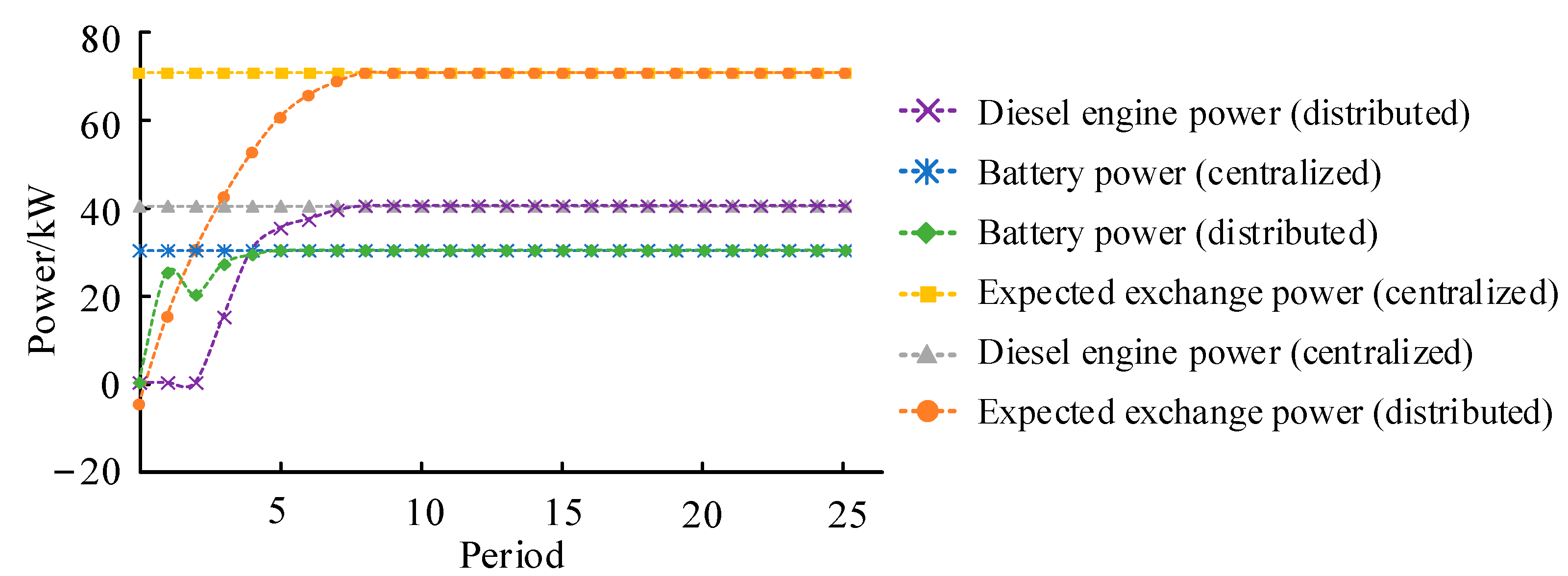
In order to demonstrate the consistency of the results between distributed optimization algorithms and centralized optimization methods, distributed and centralized algorithms were used to solve the optimization problems of microgrid clusters for comparison. Taking the 25th optimization moment as an example, Figure 10 shows the iterative process of the energy storage output, diesel engine output and expected exchange power of MG4. In addition, it was compared with the corresponding calculation results of the centralized optimization. From Figure 10, it can be seen that the energy storage and diesel engine output ultimately converged with the calculation results of the centralized algorithm after multiple iterations of the distributed optimization algorithm. Therefore, this indicated that the iterative results of the DEMPC algorithm proposed in this paper were the optimal solution.
6. Conclusions
In this paper, a microgrid optimal dispatch based on a distributed economic model predictive control algorithm was proposed. A distributed economic model predictive control algorithm was proposed for a microgrid power generation system. Firstly, the control task of the microgrid power generation system was defined in order to reduce the economic loss of the system while meeting the load demand and realize a dynamic economic optimization. Taking the requirement of meeting the load demand as the coupling constraint and working according to the actual situation of the system operation, the global objective function was designed, including minimizing the fatigue loss of each component in the wind power generation system, suppressing the fluctuation of battery power to improve the economy of the battery energy storage system and punishing constraint violations. Next, for the weighted summation multi-objective optimization problem, the Pareto frontier was obtained by changing the weight coefficient so that a reasonable compromise of the objective function could be achieved by selecting different weight coefficients.
Secondly, a detailed design method of a distributed economic model predictive controller was given. The control law obtained by iterative calculation using the Nash optimal method could effectively reduce the amount of data in the communication network. A detailed distributed economic model predictive control algorithm based on the Nash optimal method was given. Finally, a microgrid group composed of four microgrids was taken as an example for simulation verification. The simulation results showed that the distributed economic model predictive control algorithm proposed in this paper could effectively reduce the power consumption of the distributed generation system and realize the full utilization of new energy. The example showed that this strategy could effectively reduce costs and had good economic benefits. In the future, we will apply the algorithm to a wider range of microgrid clusters and extend it to microgrids connected to a big power grid.
Author Contributions
Conceptualization, Y.P. and W.J.; methodology, W.J.; software, Y.P.; validation, W.J. and J.P.; formal analysis, Y.P.; investigation, J.P.; resources, X.K.; data curation, X.K.; writing—original draft preparation, Y.P.; writing—review and editing, X.K.; visualization, X.K.; supervision, Z.Y.; project administration, Z.Y.; funding acquisition, X.W. All authors have read and agreed to the published version of the manuscript.
Funding
This project was supported by the National Natural Science Foundation of China (51877145).
Institutional Review Board Statement
Not applicable.
Informed Consent Statement
Not applicable.
Conflicts of Interest
The authors declare no conflict of interest.
References
- Rocabert, J.; Luna, A.; Blaabjerg, F.; Rodríguez, P. Control of Power Converters in AC Microgrids. IEEE Trans. Power Electron. 2012, 27, 4734–4749. [Google Scholar] [CrossRef]
- Pogaku, N.; Prodanovic, M.; Green, T.C. Modeling, Analysis and Testing of Autonomous Operation of an Inverter-Based Microgrid. IEEE Trans. Power Electron. 2007, 22, 613–625. [Google Scholar] [CrossRef] [Green Version]
- Tiwari, S.; Ongsakul, W.; Singh, J.G. Design and Simulation of an Islanded Hybrid Microgrid for Remote Off-Grid Communities. In Proceedings of the 2020 International Conference and Utility Exhibition on Energy, Environment and Climate Change (ICUE), Pattaya, Thailand, 20–22 October 2020; pp. 1–7. [Google Scholar] [CrossRef]
- Olivares, D.E.; Mehrizi-Sani, A.; Etemadi, A.H.; Canizares, C.A.; Iravani, R.; Kazerani, M.; Hajimiragha, A.H.; Gomis-Bellmunt, O.; Saeedifard, M.; Palma-Behnke, R.; et al. Trends in Microgrid Control. IEEE Trans. Smart Grid 2014, 5, 1905–1919. [Google Scholar] [CrossRef]
- Bidram, A.; Davoudi, A. Hierarchical Structure of Microgrids Control System. IEEE Trans. Smart Grid 2012, 3, 1963–1976. [Google Scholar] [CrossRef]
- Shin, Y.; Park, W.; Lee, I. Design of microgrid web services for microgrid applications. In Proceedings of the 2017 Ninth International Conference on Ubiquitous and Future Networks (ICUFN), Milan, Italy, 4–7 July 2017; pp. 818–822. [Google Scholar] [CrossRef]
- Bai, B.; Wang, K.; Bu, L.; Liu, S.; Cheng, M.; Yue, C. Feasibility Evaluation for a Multi-Energy Microgrid Case Study in China. In Proceedings of the 2019 IEEE PES Asia-Pacific Power and Energy Engineering Conference (APPEEC), Macao, China, 1–4 December 2019; pp. 1–5. [Google Scholar] [CrossRef]
- Saldarriaga-Zuluaga, S.D.; Lopez-Lezama, J.M.; Muñoz-Galeano, N. Protection Coordination in Microgrids: Current Weaknesses, Available Solutions and Future Challenges. IEEE Lat. Am. Trans. 2020, 18, 1715–1723. [Google Scholar] [CrossRef]
- Jones, C.B.; Vining, W.F.; Haines, T. Current & Future Photovoltaic System Impacts on City-Wide Grid Performance & Neighborhood Microgrids. In Proceedings of the 2022 IEEE 49th Photovoltaics Specialists Conference (PVSC), Philadelphia, PA, USA, 5–10 June 2022; pp. 0276–0282. [Google Scholar] [CrossRef]
- Li, Y.; Ma, W.; Zhang, Z.; Niu, G.; Wu, M.; Weng, Y. Energy Efficiency Evaluation of Multi-Energy Microgrid Based on Entropy-Independence-Gl Method. In Proceedings of the 2022 IEEE 5th International Electrical and Energy Conference (CIEEC), Nangjing, China, 27–29 May 2022; pp. 2232–2237. [Google Scholar] [CrossRef]
- Xiao, J.; Zhao, T.; Hai, K.L.; Wang, P. Smart energy hub—Modularized hybrid AC/DC microgrid: System design and deployment. In Proceedings of the 2017 IEEE Conference on Energy Internet and Energy System Integration (EI2), Beijing, China, 26–28 November 2017; pp. 1–6. [Google Scholar] [CrossRef]
- Parhizi, S.; Lotfi, H.; Khodaei, A.; Bahramirad, S. State of the Art in Research on Microgrids: A Review. IEEE Access 2015, 3, 890–925. [Google Scholar] [CrossRef]
- Chen, S.X.; Gooi, H.B.; Wang, M.Q. Sizing of Energy Storage for Microgrids. IEEE Trans. Smart Grid 2012, 3, 142–151. [Google Scholar] [CrossRef]
- Ishraque, M.F.; Ali, M.M. Optimized Design of a Hybrid Microgrid using Renewable Resources Considering Different Dispatch Strategies. In Proceedings of the 2021 International Conference on Automation, Control and Mechatronics for Industry 4.0 (ACMI), Rajshahi, Bangladesh, 8–9 July 2021; pp. 1–6. [Google Scholar] [CrossRef]
- Headley, A.J.; Schenkman, B.L.; Rosewater, D.M. Discrete Logic vs Optimized Dispatch for Energy Storage in a Microgrid. In Proceedings of the 2020 IEEE Power & Energy Society General Meeting (PESGM), Montreal, QC, Canada, 2–6 August 2020; pp. 1–5. [Google Scholar] [CrossRef]
- Yin, T.; Du, C.; Chen, A.; Jiang, T.; Guo, S.; Zhang, H. Improved Genetic Algorithm-Based Optimization Approach for Energy Management of Microgrid. In Proceedings of the 2020 IEEE 9th International Power Electronics and Motion Control Conference (IPEMC2020-ECCE Asia), Nanjing, China, 29 November–2 December 2020; pp. 3234–3239. [Google Scholar] [CrossRef]
- Ignat, A.; Lazar, E.; Petreus, D. Energy Management for an Islanded Microgrid Based on Particle Swarm Optimization. In Proceedings of the IEEE 24th International Symposium for Design and Technology in Electronic Packaging (SIITME), Iasi, Romania, 25–28 October 2018; pp. 213–216. [Google Scholar] [CrossRef]
- Devlin, D.; O’Sullivan, B. Preferential Attachment in Constraint Networks. In Proceedings of the 2009 21st IEEE International Conference on Tools with Artificial Intelligence, Newark, NJ, USA, 2–4 November 2009; pp. 708–715. [Google Scholar] [CrossRef]
- Ortmeyer, T.; Wu, L.; Li, J. Planning and design goals for resilient microgrids. In Proceedings of the 2016 IEEE Power & Energy Society Innovative Smart Grid Technologies Conference (ISGT), Minneapolis, MN, 9–12 October 2016; pp. 1–5. [Google Scholar] [CrossRef]
- Dalai, S.K.; Prince, S.K.; Abhishek, A.; Affijulla, S.; Panda, G. Power Management Strategies for Islanding and Grid-Connected DC Microgrid Systems with Multiple Renewable Energy Resources. In Proceedings of the 2022 IEEE Global Conference on Computing, Power and Communication Technologies (GlobConPT), New Delhi, India, 23–25 September 2022; pp. 1–6. [Google Scholar] [CrossRef]
- Navas-Fonseca, A.; Burgos-Mellado, C.; Espina, E.; Rute, E.; Gomez, J.S.; Saez, D.; Sumner, M. Distributed Predictive Secondary Control for Voltage Restoration and Economic Dispatch of Generation for DC Microgrids. In Proceedings of the 2021 IEEE Fourth International Conference on DC Microgrids (ICDCM), Arlington, VA, USA, 18–21 July 2021; pp. 1–6. [Google Scholar] [CrossRef]
- Zheng, X.; Li, H.; Chen, X.; Min, Z. Three-level microgrid inverter optimization algorithm based on model prediction control. In Proceedings of the IECON 2022—48th Annual Conference of the IEEE Industrial Electronics Society, Brussels, Belgium, 18–21 October 2022; pp. 1–6. [Google Scholar] [CrossRef]
- Selim, F.; Megahed, T.F.; Aly, M.; Shoyama, M.; Abdelkader, S.M. Model Predictive Control Based Improved Techno-Economic Control Strategy for Photovoltaic-Battery Microgrids. In Proceedings of the 2022 11th International Conference on Renewable Energy Research and Application (ICRERA), Istanbul, Turkey, 18–21 September 2022; pp. 230–235. [Google Scholar] [CrossRef]
- Yu, J.; Jin, H.; Zhang, Y.; Liu, C.; Xiao, L. A Two-stage Model Predictive Control Strategy for Economical Operation of Microgrid. In Proceedings of the 2020 15th IEEE Conference on Industrial Electronics and Applications (ICIEA), Kristiansand, Norway, 9–13 November 2020; pp. 882–887. [Google Scholar] [CrossRef]
- Guan, Y.; Vasquez, J.C.; Guerrero, J.M. Hierarchical controlled grid-connected microgrid based on a novel autonomous current sharing controller. In Proceedings of the 2015 IEEE Energy Conversion Congress and Exposition (ECCE), Montreal, QC, Canada, 20–24 September 2015; pp. 2333–2340. [Google Scholar] [CrossRef] [Green Version]
- Meng, L.; Savaghebi, M.; Andrade, F.; Vasquez, J.C.; Guerrero, J.M.; Graells, M. Microgrid central controller development and hierarchical control implementation in the intelligent microgrid lab of Aalborg University. In Proceedings of the 2015 IEEE Applied Power Electronics Conference and Exposition (APEC), Charlotte, NC, USA, 15–19 March 2015; pp. 2585–2592. [Google Scholar] [CrossRef] [Green Version]
- Muchande, S.; Thale, S. Design and Implementation of Autonomous Low Voltage DC Microgrid with Hierarchical Control. In Proceedings of the 2020 IEEE First International Conference on Smart Technologies for Power, Energy and Control (STPEC), Nagpur, India, 25–26 September 2020; pp. 1–6. [Google Scholar] [CrossRef]
- Farooq, U.; Yang, F.; Jun, Y.; Hassan, M.A.S.; Faiz, N.; Riaz, M.T.; Jinxian, L.; Shaikh, J.A. A Reliable Approach to Protect and Control of Wind Solar Hybrid DC Microgrids. In Proceedings of the 2019 IEEE 3rd Conference on Energy Internet and Energy System Integration (EI2), Changsha, China, 8–10 November 2019; pp. 348–353. [Google Scholar] [CrossRef]
- Prasanna, U.R.; Rajashekara, K. Fuel cell based hybrid power generation strategies for microgrid applications. In Proceedings of the 2015 IEEE Industry Applications Society Annual Meeting, Addison, TX, USA, 18–22 October 2015; pp. 1–7. [Google Scholar] [CrossRef]
- Liu, H.; Xie, X.; He, J.; Xu, T.; Yu, Z.; Wang, C.; Zhang, C. Subsynchronous Interaction Between Direct-Drive PMSG Based Wind Farms and Weak AC Networks. IEEE Trans. Power Syst. 2017, 32, 4708–4720. [Google Scholar] [CrossRef]
- He, L.; Wei, Z.; Yan, H.; Xv, K.-Y.; Zhao, M.-Y.; Cheng, S. A Day-ahead Scheduling Optimization Model of Multi-Microgrid Considering Interactive Power Control. In Proceedings of the 2019 4th International Conference on Intelligent Green Building and Smart Grid (IGBSG), Yichang, China, 6–9 September 2019; pp. 666–669. [Google Scholar] [CrossRef]
- Picioroaga, I.I.; Tudose, A.; Sidea, D.O.; Bulac, C.; Eremia, M. Two-level Scheduling Optimization of Multi-microgrids Operation in Smart Distribution Networks. In Proceedings of the 2020 International Conference and Exposition on Electrical and Power Engineering (EPE), Iasi, Romania, 22–23 October 2020; pp. 407–412. [Google Scholar] [CrossRef]
- Huo, Z.-H.; Wang, P.; Zhang, S.-J.; Wang, D.; Kong, Z. A Two-Step Multi-objective Optimization Frame-work for Microgrid Scheduling Problem Based on Cloud-edge Computing. In Proceedings of the 2020 IEEE 4th Conference on Energy Internet and Energy System Integration (EI2), Wuhan, China, 30 October–1 November 2020; pp. 2764–2768. [Google Scholar] [CrossRef]
- Li, B.; Wang, J.; Xia, N. Dynamic Optimal Scheduling of Microgrid Based on ε constraint multi-objective Biogeography-based Optimization Algorithm. In Proceedings of the 2020 5th International Conference on Automation, Control and Robotics Engineering (CACRE), Dalian, China, 19–20 September 2020; pp. 389–393. [Google Scholar] [CrossRef]
Figure 1.
Structure diagram of microgrid power generation system.
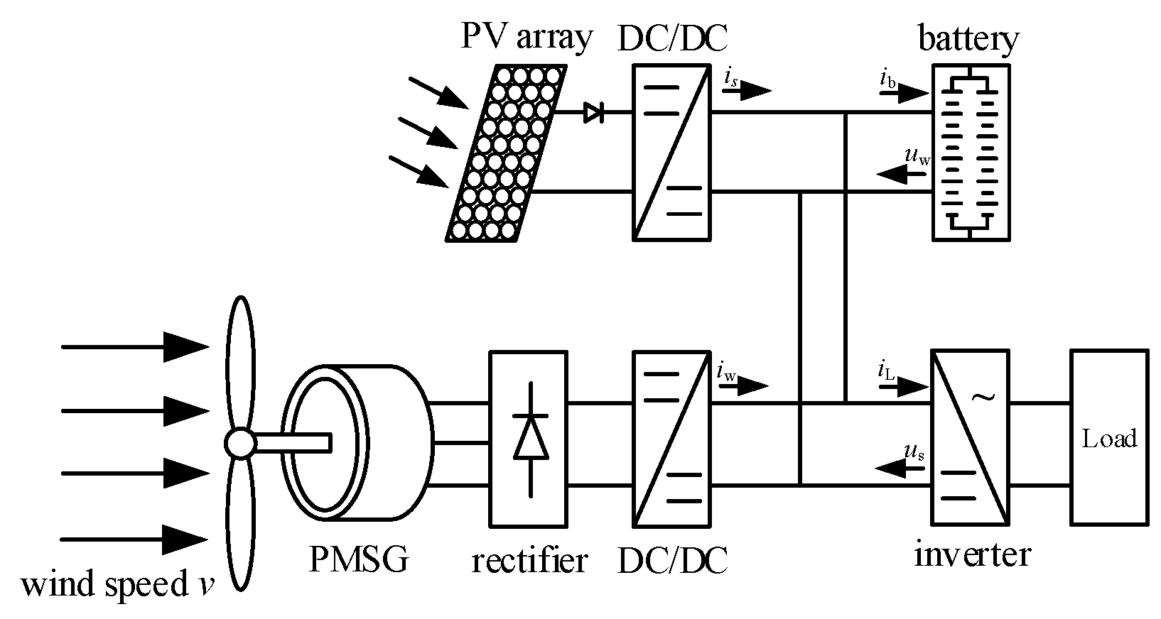
Figure 2.
Micro electric network cluster structure.
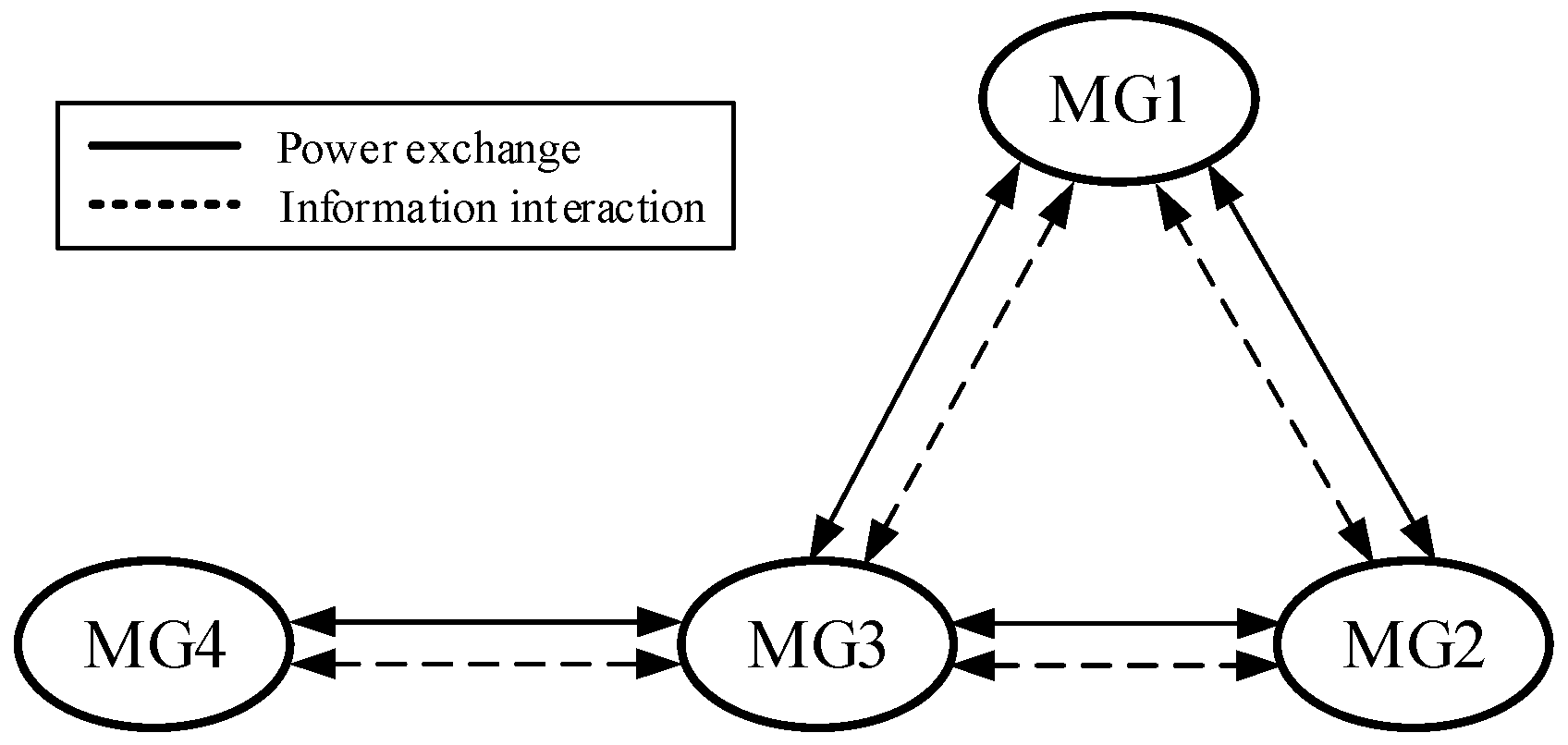
Figure 3.
The flowchart of workflow.

Figure 4.
The DEMPC algorithm flow chart.
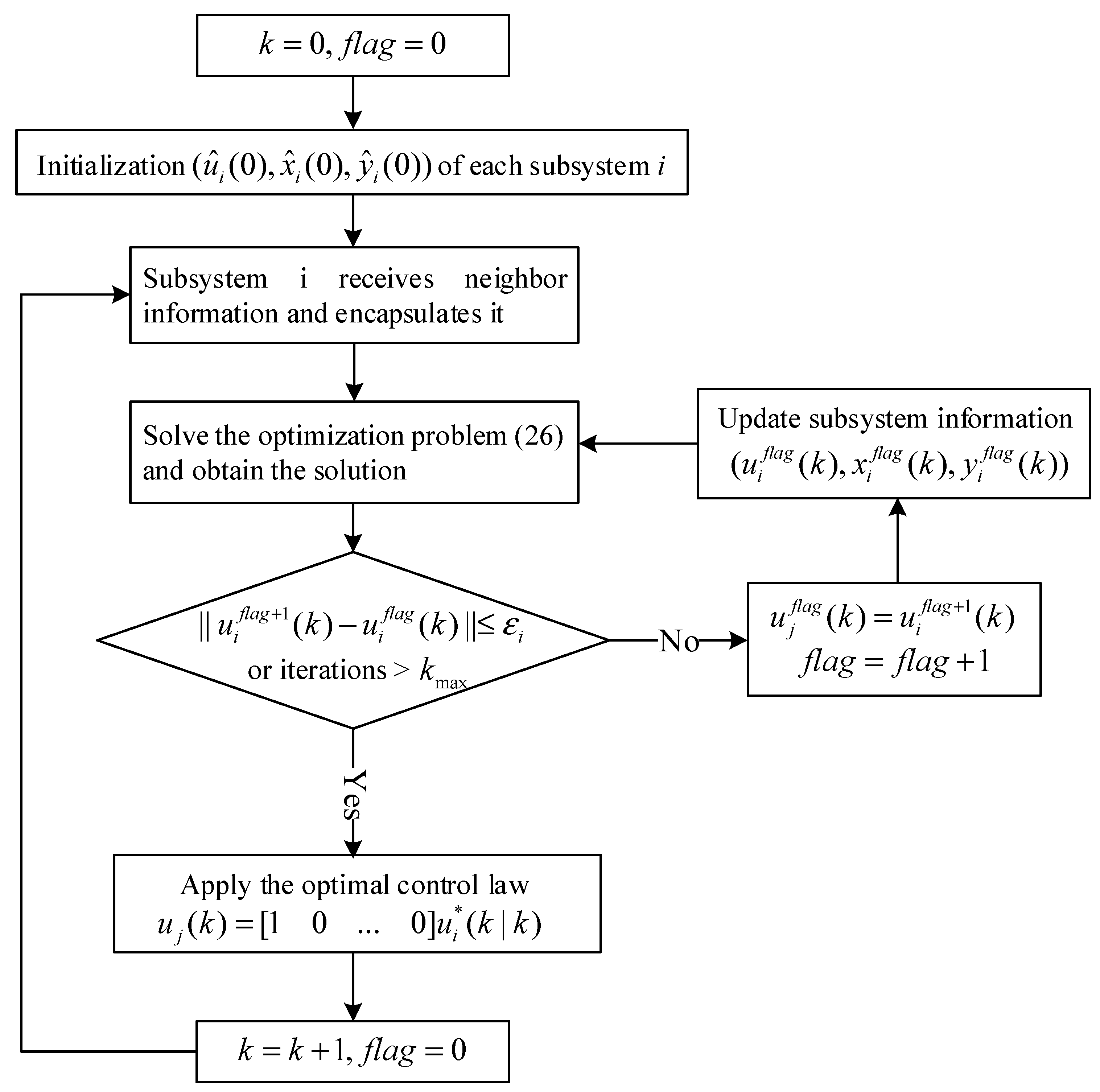
Figure 5.
Curves of PV output power, WT output power and load for MG1 to MG4.

Figure 6.
Optimization results for MG1 to MG4.
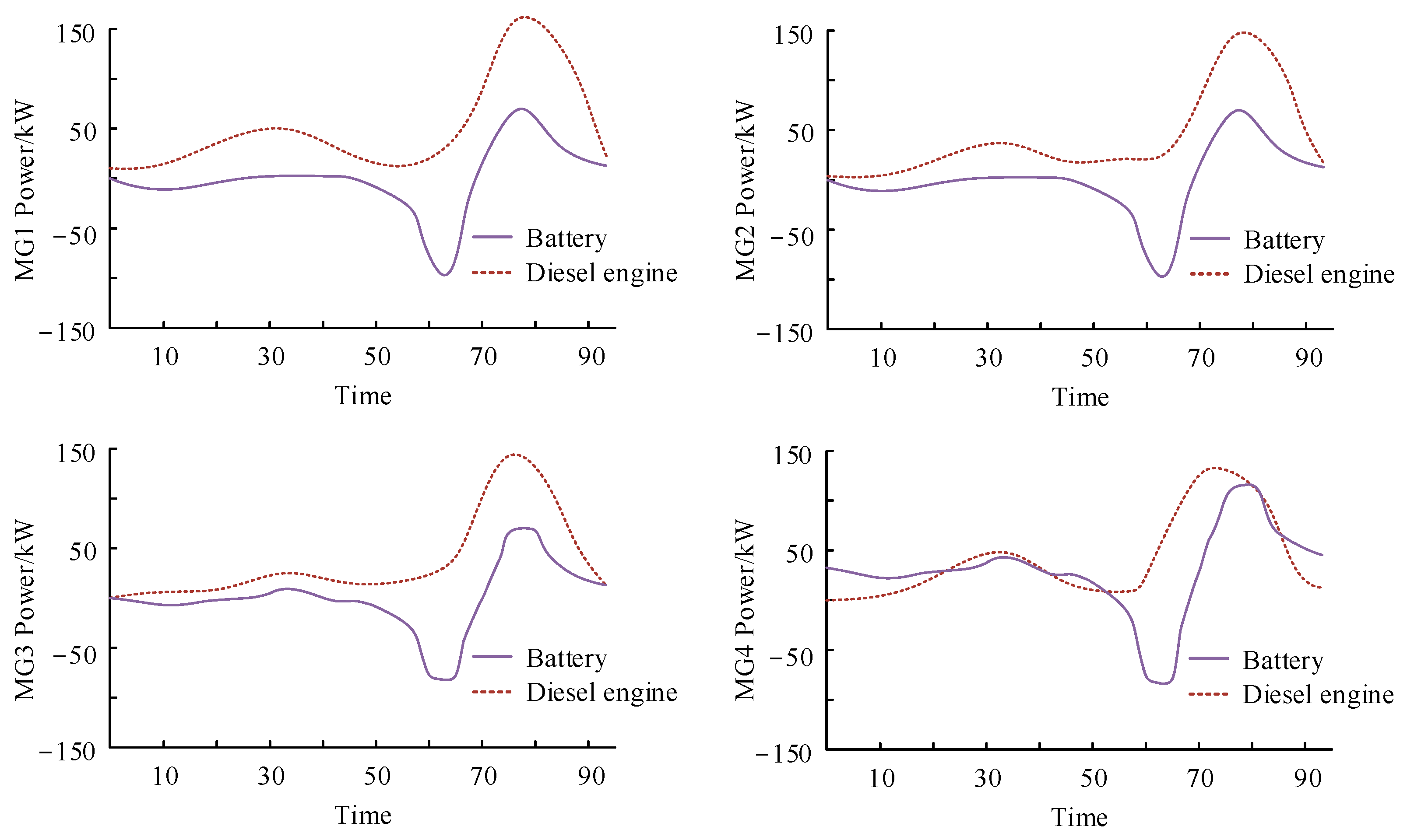
Figure 7.
Optimization results of exchange power.
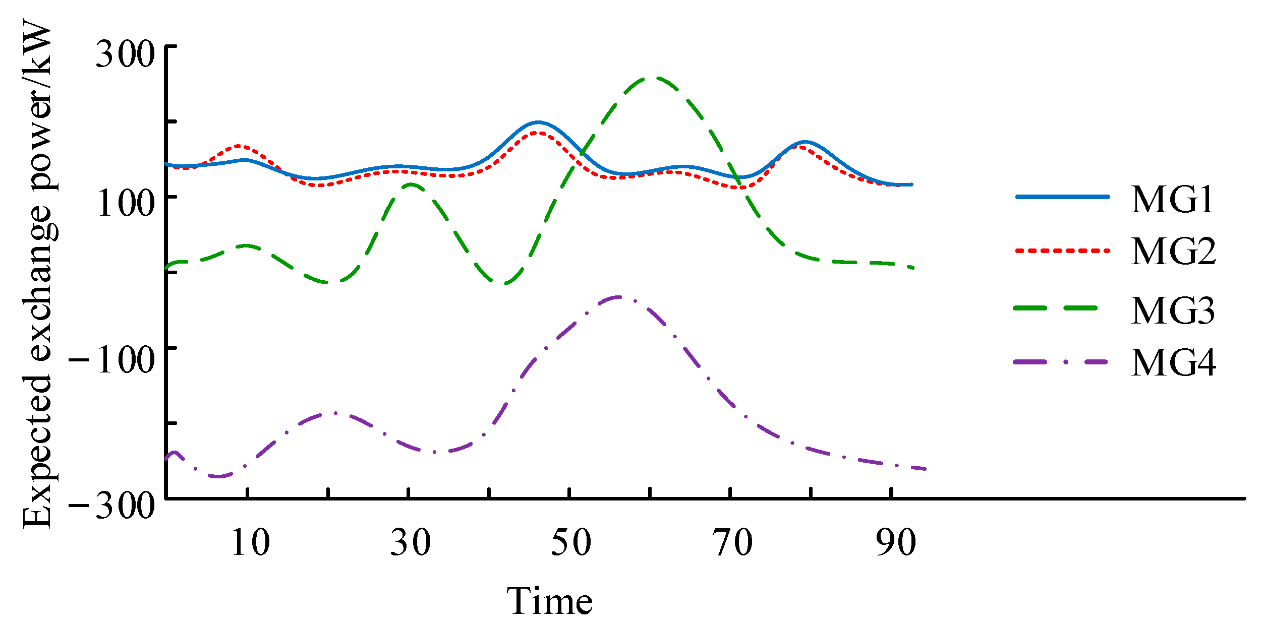
Figure 8.
The convergence of residuals in optimization.

Figure 9.
Changes in expected exchange power of each MG during iteration.

Figure 10.
Comparison of distributed optimization and centralized optimization.

Table 1.
DG configuration of each microgrid.
| Microgrid | Photovoltaic Rated Power/kW | Fan Rated Power/kW | Diesel Engine Rated Power/kW | Battery Rated Power/kW, Rated Capacity (kW·h) |
|---|---|---|---|---|
| MG1 | 350 | 600 | 300 | 200,800 |
| MG2 | 450 | 650 | 300 | 230,900 |
| MG3 | 800 | — | 400 | 230,100 |
| MG4 | 350 | 550 | 250 | 200,800 |
Disclaimer/Publisher’s Note: The statements, opinions and data contained in all publications are solely those of the individual author(s) and contributor(s) and not of MDPI and/or the editor(s). MDPI and/or the editor(s) disclaim responsibility for any injury to people or property resulting from any ideas, methods, instructions or products referred to in the content. |
© 2023 by the authors. Licensee MDPI, Basel, Switzerland. This article is an open access article distributed under the terms and conditions of the Creative Commons Attribution (CC BY) license (https://creativecommons.org/licenses/by/4.0/).
Share and Cite
MDPI and ACS Style
Peng, Y.; Jiang, W.; Wei, X.; Pan, J.; Kong, X.; Yang, Z. Microgrid Optimal Dispatch Based on Distributed Economic Model Predictive Control Algorithm. Energies 2023, 16, 4658. https://doi.org/10.3390/en16124658
AMA Style
Peng Y, Jiang W, Wei X, Pan J, Kong X, Yang Z. Microgrid Optimal Dispatch Based on Distributed Economic Model Predictive Control Algorithm. Energies. 2023; 16(12):4658. https://doi.org/10.3390/en16124658
Chicago/Turabian StylePeng, Yuxiang, Wenqian Jiang, Xingqiu Wei, Juntao Pan, Xiangyu Kong, and Zhou Yang. 2023. "Microgrid Optimal Dispatch Based on Distributed Economic Model Predictive Control Algorithm" Energies 16, no. 12: 4658. https://doi.org/10.3390/en16124658
Note that from the first issue of 2016, this journal uses article numbers instead of page numbers. See further details here.