Article

On the Use of Ultrasonic Flowmeters for Cooling Energy Metering and Sub-Metering in Direct Expansion Systems

1
Department of Industrial Engineering, University of Salerno, Via Giovanni Paolo II 132, 84084 Fisciano, SA, Italy
2
Department of Civil and Mechanical Engineering, University of Cassino and Southern Lazio, Via G. Di Biasio 43, 03043 Cassino, FR, Italy
3
Department of Civil, Environmental and Architecture Engineering, University of Cagliari, Via Marengo 2, 09123 Cagliari, CA, Italy
*
Author to whom correspondence should be addressed.
Energies 2023, 16(12), 4775; https://doi.org/10.3390/en16124775
Submission received: 22 May 2023 / Revised: 11 June 2023 / Accepted: 14 June 2023 / Published: 17 June 2023
(This article belongs to the Topic Cooling Technologies and Applications)

Abstract

:
The Energy Efficiency Directive (EED, Directive 2012/27/EU) has made mandatory the installation of individual metering systems in the case of buildings with centralized heating/cooling and hot water sources (multi-apartment and multi-purpose buildings), provided it is economically and technically feasible. Individual metering of heating/cooling systems is mainly based on thermal energy meters (TEM), which are widely used for direct metering in heating applications. On the other hand, direct metering of energy consumption in cooling systems still represents a challenge, given the different types of cooling units and the lack of regulations from the technical and legal points of view. In this context, this paper briefly overviews the available centralized cooling systems and the possible solutions for metering and sub-metering, which depend on the specific application. Vapour Compression Refrigeration (VCR) systems are spreading worldwide for air conditioning applications. Particular attention has been paid to the direct metering of cooling energy and specifically to refrigerant flow rate measurement, which represents a critical issue because of the small-diameter pipes and the different thermodynamic properties of the fluid used. Thus, an experimental campaign has been developed and carried out in order to compare a clamp-on ultrasonic flowmeter with a more accurate Coriolis one in a direct expansion (DE) system. The experimental tests have been performed at two different temperature conditions, showing a relative error in the mass flow rate measurements within ±10%.

1. Introduction

Heating, ventilation, and air conditioning systems (HVAC) are currently the most commonly used devices to reach and maintain thermal comfort in buildings. Unfortunately, these systems are electricity-intensive. In the last two decades, developed and developing countries have been experiencing a dramatic increase in energy demand and greenhouse gas emissions. The building sector accounts for 40% of the final energy consumed globally [1,2,3,4], with about 40–70% related to space heating [5,6,7]. Several factors (e.g., incomes and population growth) are contributing to an evident increase in the energy consumption related to the building sector [5].
Moreover, time spent indoors is increasing [8,9], causing a rise in the sales of air conditioners (about 100 million devices annually [10]), contributing to the increase in energy consumption, especially when considering cooling energy demand, as discussed by IEA in [10] and shown in Figure 1.
Energy efficiency in this sector is becoming a more and more significant challenge, which is evident when also considering that, as described in reference [11], the cooling load and consequently the cooling demand strictly depend on solar radiation, the urban heat island effect, and internal heat gains [11].
Energy efficiency in individual dwellings involves energy management and policy, metrology, and behavioural aspects, and it is a very debated topic among the research community. The first European attempt to regulate temperature control and heat accounting systems for individual dwellings is indirectly represented by Directive 93/76 [12]. It suggests that energy consumption and CO2 emissions can be limited by billing air conditioning, heating, and hot water costs based on the actual energy consumption. Subsequent directives (2002/91 [3] and 2010/31 [13]) also identified the end-user’s awareness as a functional tool for energy efficiency, intending to achieve the 20-20-20 goals. Directive 2012/27/EU (Energy Efficiency Directive—EED [14]) has made mandatory for the Member States the installation of individual energy-metering systems in the case of buildings with centralized heating/cooling and hot water sources (multi-apartment and multi-purpose buildings), provided it is economically and technically feasible [14,15].
Centralized heating systems in multi-apartment buildings generally promise better performance in terms of energy and economic savings [16]. Unfortunately, the potential savings achievable are strictly related to the specific thermophysical properties and cooling/heating systems of buildings, as well as to behavioural aspects [17,18,19], resulting in unpredictable overall savings, leading to different transpositions of the EED within the EU Member States. In fact, some of them have made mandatory the installation of individual heat-metering systems for all the buildings, while others have exempted all of their building stock [20].
To date, technical and legislative implications still represent an open topic. The obligation to implement individual metering systems is subject to technical and economic feasibility [14,15], without official indications regarding reference values of energy saving and/or standard costs. In addition, current legislation does not specify if the feasibility analysis should be performed at standard or operational/real conditions of the buildings. Therefore, some tools/guidelines have been proposed within the Member States for performing feasibility analysis of metering and accounting systems [21].
Individual metering systems usually consist of one or more devices installed at the generators (metering level) and a set of sub-meters installed at the terminal units (end-users’ location) to allocate the energy costs. Metering systems are usually simpler than sub-metering ones, as the energy consumed at the generator can be directly measured by means of heat, electricity, or gas meters. The sub-metering level is often more challenging, as different types of terminal units need different sub-metering approaches. In general, metering and sub-metering systems are divided into direct energy meters and indirect energy meters. The first category refers to systems able to measure the “true” thermal energy exchanged. Thermal energy meters (or heat meters) are unique direct heat-metering systems regulated by the Measuring Instrument Directive (MID [22]) and can be either complete devices or combined instruments consisting of separate sub-assemblies (a flow sensor, a temperature sensor pair, and a calculator). The second category includes systems measuring different parameters that are proportional or somehow closely related to energy consumption, allowing individual dwelling heat costs to be allocated as a fraction of the total energy consumption of the building. The choice between the two methods is commonly related to the specific application and to the systems/building constraints.
While the analysis of the scientific literature is quite rich in studies regarding metrological aspects [23,24,25], technical–economic feasibility [26], energy efficiency [26,27], and cost allocation [28] in the field of heating systems, cooling energy metering has not yet been systematically analysed, especially in sub-metering applications, where major technical and economic constraints are present with respect to the measurement of thermal energy at the metering level.
Centralized Cooling Systems (CCS) and district cooling networks still show a limited spread compared to heating ones [11]; therefore, cooling energy metering, specifically direct metering, represents an almost unexplored research field. Most studies focus on Vapour Compression Refrigeration (VCR)-based units, which are the most widely used systems in refrigeration and air conditioning applications (market share of 80% [29]). Regarding environmental performance, these systems also contribute to greenhouse gas emissions because of the high GWP (Global Warming Potential) of the refrigerants used (direct emissions). In this regard, numerous studies regarding retrofit/drop-in of new low-GWP refrigerants in air conditioning or refrigeration applications have evaluated the related environmental impact change by means of COP (Coefficient Of Performance), TEWI (Total Equivalent Warming Impact), and/or more sophisticated ETEWI (Expanded Total Equivalent Warming Impact) analysis [30,31,32,33].
Variable Refrigerant Flow (VRF) units are VCR-type systems able to provide heating or cooling energy to different locations simultaneously. In these devices, the refrigerant flow rate is controlled by means of a variable-speed compressor (outdoor unit) and by electronic expansion valves (indoor units). Thanks to their control and maintenance simplicity and their part-load performances, these devices are gaining more and more attention within the centralized air conditioning market. In commercially available VRF systems, energy and cost allocation is usually performed in an indirect way by means of a proprietary calculation algorithm. These algorithms are mainly based on the evaluation of the quantity of refrigerant used by internal units depending on the opening and closing impulses of the electronic valves, so the share of effective use is assigned accordingly. However, direct metering methods have been proven to be more reliable in thermal energy cost allocation. In order to evaluate the energy performances of VRF systems, as well as those of VCR systems in general, it is necessary to take measurements of both electricity and cooling/heating energy. The former is relatively simple to obtain by means of high-accuracy power meters [34,35], so heating/cooling energy represents the key factor in evaluating the performances of these systems. With this in mind, researchers have focused their attention on air specific enthalpy difference and refrigerant specific enthalpy difference methods. The air specific enthalpy difference is based on metering the air flow rate and the specific enthalpy difference (between the inlet and outlet sections) at the indoor and outdoor units. Unfortunately, even if this method could be easily implemented, it cannot guarantee a sufficient level of accuracy. Consequently, a specific refrigerant enthalpy difference method has been developed. The heating/cooling capacity of a VRF system can be evaluated by measuring the refrigerant flow rate and the inlet–outlet specific enthalpy difference in the indoor units. The actual challenge is to measure the refrigerant flow rate, as flowmeters are often expensive and/or require cooling circuit modifications to be used. Different non-intrusive methods have been proposed in the scientific literature, based on the throttling characteristics of electronic expansion valves, pressure drop, and refrigerant density [36,37] or considering the volumetric efficiency of the compressor [38]. In 2021, Xiao et al. [39] proposed three new metering methods for VRF systems, based respectively on machine learning, a throttling model, and an electronic expansion valve. The three methods respectively showed accuracies of 6.9%, 6.0%, and 7.8%. Unfortunately, the above-mentioned methods strictly depend on the specific application and cooling system, so the measurement of refrigerant flow rate still represents a challenge for evaluating cooling performances, especially because of the typically small diameters of the pipes.

Aim of the Paper

In the above-described context, the aim of this work is to bridge the gap of knowledge concerning cooling energy metering and sub-metering applications, specifically by providing the following:
(a)
a systematic classification of the existing CCS, with particular reference to the technical characteristics determining the configuration of direct metering systems and of the available direct metering and sub-metering techniques;
(b)
an experimental evaluation of the metrological reliability of a clamp-on ultrasonic flowmeter used to measure the cooling energy of a direct expansion system.
The direct expansion systems were chosen given the vast diffusion of these systems for space cooling, while the non-intrusive clamp-on ultrasonic flowmeters were analysed for two main reasons: (i) they could be used both in metering (as sub-assemblies of thermal energy meters) and in sub-metering applications; (ii) they could meet the non-invasive and limited cost requirements. Finally, the analysis is currently focused only on direct measurement techniques because they have proven to be more reliable in thermal energy cost allocation.

2. Direct Metering in Centralized Cooling Systems

A centralized cooling system can be divided into three sub-components:
(a)
Central generation unit;
(b)
Distribution system;
(c)
Terminal units located at the end-users’ location.
Several cooling systems are currently available on the market. Classification is usually based on the heat transfer fluid and the distribution circuit characteristics. The applicable metering and sub-metering systems also depend on the specific cooling system, as different heat transfer fluid and distribution systems require different approaches.
A thermal energy meter (TEM) is able to measure thermal energy taken or released by a heat transfer fluid (HTF) in a heat exchanger/heat exchange circuit by applying an energy balance to an open system, under the following hypotheses:
(i)
One-dimensional and stationary motion field;
(ii)
Single inlet and outlet sections;
(iii)
Negligible changes in potential and kinetic energy.
Therefore, thermal energy exchanged in a time interval can be evaluated by integrating the difference in enthalpy of the HTF between the outlet and inlet sections with respect to time, as shown in Equation (1):
Q = t ρ · V ˙ · h o u t h i n d t
where Q is the thermal energy k W h , ρ   k g · m 3 is the density of the heat transfer fluid, V ˙ is the volumetric flow rate m 3 · s 1 , and h o u t and h i n are the specific enthalpies of the outlet and the inlet sections, respectively k J · k g 1 .
As can be seen from Equation (1), evaluating the thermal energy exchange requires knowledge of the following:
(a)
The specific heat transfer fluid, to evaluate its thermodynamic properties (i.e., density and enthalpies);
(b)
The type of distribution system;
(c)
The type of terminal units;
(d)
Regulation modes (e.g., Variable Air Volume, Variable Refrigerant Flow).
In the following subsections, the different centralized cooling systems and the respective metering and sub-metering methods are described and discussed.
In Table 1, a classification of different centralized cooling systems is reported. In addition, the applicable direct metering and sub-metering systems are specified.

2.1. All-Air Cooling Systems

An all-air system mainly consists of the following:
  • Generation system, for the production of cold/hot water;
  • An Air Handling Unit (AHU), in which the air undergoes the transformations of cooling, dehumidification, and post-heating;
  • Air delivery systems;
  • Inlet and extraction vents.
In many cases, the air delivery system also includes a return system, in which air from the conditioned space is drawn and sent to the AHU to be mixed with the supply air.
All-air systems can be divided into Constant Air Volume (CAV), in which the supply air temperature can be varied and the supply air volume is constant, and Variable Air Volume (VAV) systems, in which the supply air volume can be varied to supply air at a constant temperature and meet different cooling/heating demands. The thermal energy at the sub-metering level is measured according to Equation (1) by using temperature and relative humidity probes (to evaluate the air specific enthalpies at the inlet/outlet sections) and mass/volume flowmeters.
Different sub-metering conditions can be found, according to the specific configuration of the multi-zone all-air system:
(a)
All-air system with dedicated AHU for each end-user. In this case, sub-metering consists of measuring the thermal energy on the primary water circuits (hot/cold coils of the AHUs). In addition, the electricity used for auxiliary systems should also be measured.
(b)
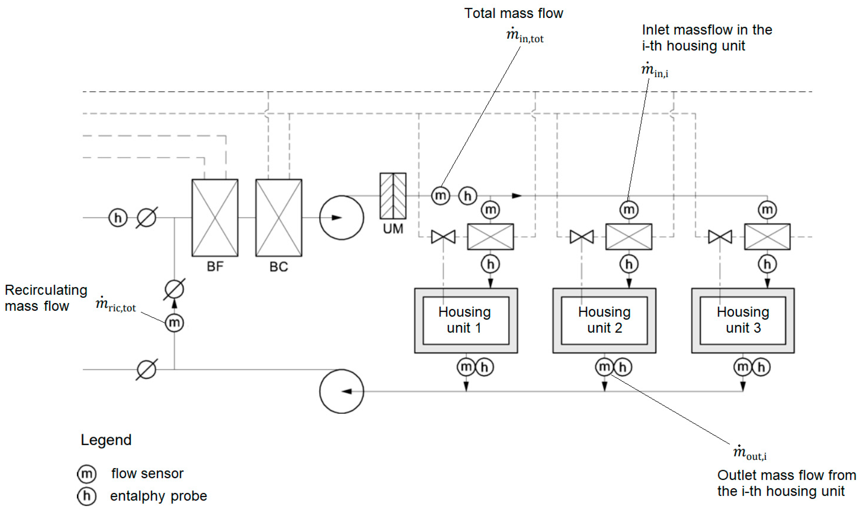
Variable Air Volume systems, in which a single AHU serves several housing units. Sub-metering requires the measurement of the inlet air flow at each housing unit together with the inlet specific enthalpy. In the case of air recirculation, the relationship between the inlet and recirculated air flow rates should also be known.
(c)
Constant Air Volume systems, in which a single AHU serves several housing units, as in the previous configuration. Enthalpy of delivery and return of humid air must be measured for sub-metering purposes for each end-user (air flow rate is known and constant).
(d)
Systems with double hot/cold ducts. In this case, thermal power can be measured before (separately) or after the mixing section.
A single-duct all-air VAV system in which a central AHU serves several users is represented in Figure 2, together with a possible sub-metering system configuration.
In the case of a simple system operating with a single duct (as that shown in Figure 1), with a constant air mass flow rate in each zone, the thermal energy exchanged at each i-th location can be calculated by using Equation (2), valid for both cooling and heating applications.
Q i = m ˙ i n , i · h i n , i 1 m ˙ r i c , t o t m ˙ i n , t o t · h e x t m ˙ r i c , t o t m ˙ i n , t o t · h o u t , i d t
where the following variables are included:
  • m ˙ i n , i and m ˙ o u t , i [ k g · s 1 ] are the inlet and outlet air mass flow rates, respectively, in the i-th housing unit;
  • m ˙ i n , t o t and m ˙ r i c , t o t [ k g · s 1 ] are the total air mass flow rate introduced and recirculated, respectively;
  • h i n , i and h o u t , i [ k J · k g 1 ] are the specific enthalpies of the inlet and outlet air in the i-th housing unit;
  • h e x t is the specific enthalpy of the outdoor air;
  • t is the time [h].
The cost of individual metering systems may be reduced in VAV systems by assuming the specific enthalpy of the outlet air of every housing unit is equal to the conventional comfort value. Similarly, in the case of absence of post-heating, the specific enthalpy of the inlet air of each housing unit can be set as constant. In this way, if a lower accuracy is acceptable, the sub-metering system would consist only of the inlet air flowmeters and three enthalpy probes (to measure h i n , t o t , h o u t , t o t , and h e x t ).
A similar method to reduce metering costs for CAV systems consists of considering the inlet air flow rates that are known and equal to the design value. In this way, only inlet/outlet enthalpies in housing units and the outdoor air enthalpy must be measured. Distribution losses can be evaluated by difference between the total energy supply (total energy consumption) and the values measured in all the housing units.

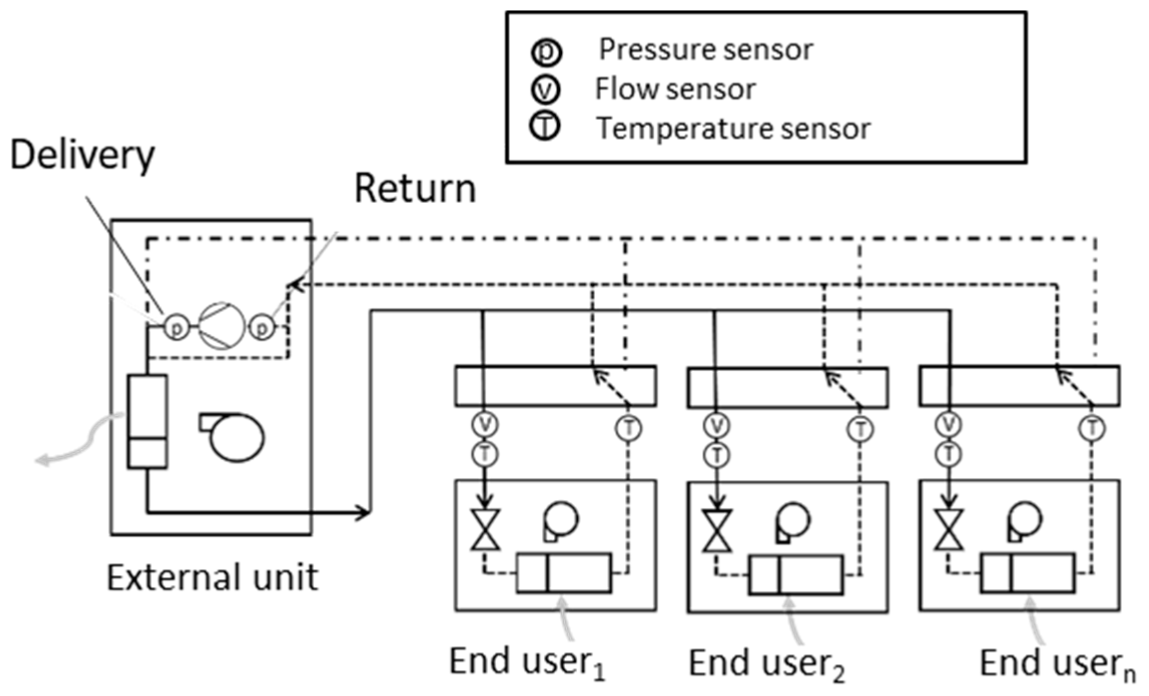
2.2. All-Water Cooling Systems

In all-water cooling systems, the heat transfer fluid is water. They mainly consist of:
  • Generation system, for the production of cold/hot water;
  • Water distribution pipes (two pipes or four pipes to obtain independent circuits for hot and cold water);
  • Emission systems. Different terminal units can be used, from the simplest single-coil ones (e.g., fan-coils, convectors, or radiant panels) to multiple-coil units.
In an all-water system, the thermal energy can be measured according to Equation (3).
Q = t ρ · V ˙ · c p · T o u t T i n d t
where the following variables are included:
  • T i n and T o u t [K] are the flow and return temperatures, respectively;
  • c p [ k J · k g 1 · K 1 ] is the specific heat (average) of the heat transfer fluid.
In order to measure thermal energy exchanged, it is possible to use a TEM consisting of a flowmeter, two temperature sensors, and a calculator.
In all-water systems, the cooling/heating energy consumption can be measured in different ways according to the desired accuracy, by measuring the following quantities:
  • Thermal energy subtracted (cooling and dehumidification);
  • Thermal energy provided (heating, post-heating, and humidification).
Electricity meters can be used to measure electricity consumption for auxiliaries and ventilation. Figure 3 shows a direct metering configuration for an all-water system.
In the case of terminal units characterized by two heat exchangers, modern TEMs are able to measure cooling and heating energy consumption separately.

2.3. Air–Water Cooling Systems

Air–water systems can be seen as hybrid systems involving both all-air and all-water systems’ characteristics. In particular, a centralized all-air system provides primary air to the end-users’ location in saturated (or almost saturated) conditions. At the same time, chilled/hot water is distributed (as in all-water systems) to the terminal units, which can be those used in all-water systems. In this way, primary air provided by the air distribution system is cooled or heated by means of the water-based terminal units. An individual metering system depends on the specific system configuration, and it is formed by a combination of metering and sub-metering devices related to all-air and all-water systems.

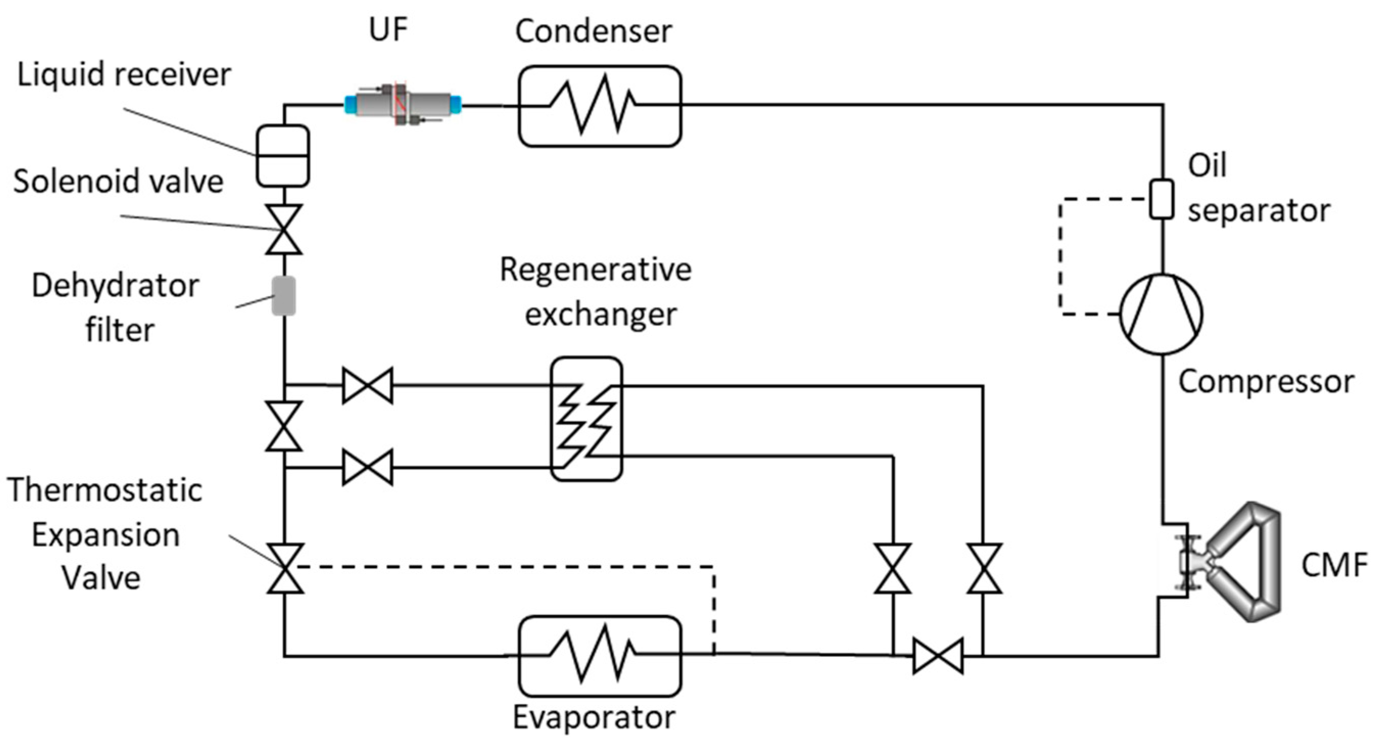
2.4. Direct Expansion Cooling Systems

In Direct Expansion (DE) systems, the heat transfer fluid is a refrigerant, and the cooling/heating effect is provided according to the Vapour Compression Refrigeration technology. They are also called mono/multi-split air conditioning systems and can be divided into Variable Refrigerant Volume (VRV) and Variable Refrigerant Flow (VRF) systems.
A DE system mainly consists of the following:
  • An outdoor unit, including the compressor and a heat exchanger, acting as condenser or evaporator in cooling or heating application, respectively;
  • Several indoor units, each one including an electronic thermostatic valve, a heat exchanger, a fan, and a diverter valve.
The distribution system is made up of two or three pipes connecting the indoor units to the outdoor one.
Figure 4 shows a three-pipe VRV/VRF system with the corresponding metering and sub-metering systems.
Regarding the outdoor unit, pressure sensors are placed directly at the inlet and outlet sections (or on the delivery/return pipes) of the compressor. The sub-metering systems consist of a flowmeter and a temperature sensor pair placed externally to the indoor units. Therefore, it is possible to measure the energy consumption at each housing unit according to Equation (4):
Q i = t ρ R · V ˙ · h i d t
where ρ R is the refrigerant density and h is the specific enthalpy difference between the outlet and the inlet section of the i-th internal units.
To solve Equation (4), it is necessary to measure/calculate the following:
  • The refrigerant pressure at the inlet and outlet sections of the compressor;
  • The refrigerant temperature at the inlet and outlet sections of the i-th internal unit;
  • The refrigerant enthalpy at the inlet and outlet sections of the i-th internal unit;
  • The refrigerant density ρ R ;
  • The refrigerant volume flow rate V ˙ at the inlet section of the i-th internal unit.

3. Experimental Setup and Tests

This section presents a detailed account of the experimental methodology to facilitate readers replicating the experimental campaign.
As previously discussed (see Table 1), direct metering in CCS can be performed by means of TEMs, temperature/enthalpy probes, electricity meters, and flowmeters. Flowmeters can be separate subassemblies of a TEM, being used both in metering and sub-metering applications, or energy cost allocation tools at the sub-metering level.
In DE systems, pressures and temperatures are relatively simple to measure, while refrigerant flow rate measurement still represents a challenge in terms of costs and installation. Starting from this consideration, the authors have designed and performed several experimental tests involving a DE system operating at two different indoor and outdoor temperature conditions and three different compressor speed values, with the aim of comparing the refrigerant flow rate measured by two different flowmeters: an ultrasonic clamp-on sensor and a Coriolis one.
A clamp-on ultrasonic flowmeter mainly consists of two ultrasonic transducers acting alternatively as transmitter and receiver and positioned externally to the pipes. The difference between the transit times needed for the soundwaves emitted by the transmitter to reach the receiver (and reverse) allows measuring the fluid flow rate. When using a Coriolis flowmeter, a liquid (or a gas) flows through a vibrating tube. This vibration introduces a Coriolis acceleration, producing a measurable twisting force on the tube. The Coriolis flowmeter is then able to measure mass flow rate (in both forward and reverse directions) by detecting the resulting angular momentum. Coriolis flowmeters usually show better accuracies, unlike the clamp-on ultrasonic ones, which allow a reduction in installation and maintenance costs, since transducers are placed on the external side of the refrigerant pipes.
The DE system used for performance evaluation in this experimental campaign consists of the following:
  • Rotary scroll compressor characterized by a displacement of 10.8 cm3 and able to provide a cooling capacity of 2.55 kW when operating at 220 V (AC) and 50 Hz (single-phase);
  • Thermostatic expansion valve with external equalization, with operating temperatures between −40 °C and +10 °C and maximum operating pressures of 45.5 bar;
  • Finned-tube evaporator, with a nominal volume air flow rate of 1400 m3/h;
  • Finned-tube condenser, with a nominal volume air flow rate of 2200 m3/h;
  • Tube-in-tube internal heat exchanger (not used in this experimental campaign);
  • 10 mm diameter copper pipes with a thickness of 1 mm;
  • R410a as heat transfer fluid.
Other components and security devices are also installed, such as oil separator, dehydrator filter, and liquid receiver.
Several temperatures (4-wire Pt100, accuracy of ±0.15 °C) and pressure sensors (piezoresistive type, accuracy of ±0.1 bar) are used to measure the thermodynamic properties of the refrigerant. The refrigerant pressure was measured at both the low-pressure and the high-pressure sides, in particular at the inlet and outlet sections of the compressor, the condenser, the TEV, and the evaporator. The refrigerant temperature was measured at the same point of the system. The temperature of the air at the inlet and outlet sections of the evaporator and condenser was also measured. Regarding the electricity consumption for the system supply (compressor and auxiliaries), a wattmeter with an accuracy of ±4.2 W was used.
Figure 5 shows the schematic of the refrigeration system, with the addition of the Coriolis flowmeter (CMF) and the clamp-on ultrasonic flowmeter (UF).
The ultrasonic flowmeter is manufactured by ISOIL Industria, Cinisello Balsamo, Italy and is characterized by a diameter range between 10 mm and 150 mm, a fluid velocity range between 0.01 m/s and 25 m/s, and a declared accuracy within the range of 1–3%. This is, of course, a purely theoretical value, to be verified in the field in relation to the actual installation and operating conditions of the system. The transducers were installed downstream of the condenser to measure the volume flow rate of the refrigerant when it is in liquid state. In particular, the UF was installed far from elbows and bends of the pipe according to the manufacturer’s instructions. The refrigerant density in each operating condition was calculated via REFPROP (version 10.0) software [40]. Figure 6 shows the clamp-on ultrasonic flowmeter used during the experimental tests.
The Coriolis mass flowmeter (CMF) is characterized by a declared accuracy within 0.35%. It was installed upstream of the compressor to measure the superheated vapor refrigerant mass flow rate.
Experimental tests were performed at stationary operating conditions, with a duration of each test of 15 min after reaching the stationary conditions. Indoor and outdoor air temperatures were controlled by means of electric heaters in order to reach and maintain two different environmental conditions. In addition, the compressor rotation speed was also controlled by means of an inverter in order to test three different values (i.e., 30, 40 and 50 Hz), so six operating conditions were tested. The 2 different indoor/outdoor conditions refer to 23/29 °C and 20/35 °C, referring to the temperature of the air entering the evaporator/condenser, respectively, as reported in Table 2.
Since different setups (in terms of indoor/outdoor temperatures and compressor frequency) correspond to different operating mass flow rates, it was possible to evaluate the reliability of the clamp-on ultrasonic flowmeter in a wide range of operating conditions. For each setup, three tests were performed in order to verify repeatability.

4. Results and Discussion

The results of the tests performed are shown in Table 3. For both the Coriolis mass flowmeter and the ultrasonic one, the mass flow rates are reported in terms of average value and standard deviation, calculated considering the measured values during the testing time (n values). In addition, the calculated relative percentage error (RE) is also evaluated, considering the CMF reading as a reference. Indeed, the CMF is a well-established mass flow-metering technology, showing higher metrological performance and reliability due to its gravimetric measuring principle compared to the volumetric one of the UF meter. In the literature, several experiments that used a CMF as a master meter are available [41,42].
In some tests, the coupling signal of the ultrasonic flowmeter showed an anomalous trend. The reason for this is probably related to the fact that the diameter of the refrigerant pipe where the transducers were installed is at the lower bound of the ultrasonic flowmeter’s range.
As can be seen from Table 3, except for the tests performed at 23/29 °C, at 40 Hz and 50 Hz, the ultrasonic flowmeter did not show a good repeatability. In 5 out of 18 tests performed, the relative percentage error exceeded 10%, reaching values over 20% in 2 of them, while in 5 other tests, the absolute RE was in the range 5–10%.
As a sub-assembly of a TEM, the ultrasonic flowmeter module must comply with the Maximum Permissible Error (MPE) established by the harmonized technical standard EN 1434-1 [43] and legal metrology recommendation OIML R75-1 [42]. In particular, in the typical case of a flowmeter with permanent flow rate (qp) equal to 1.5 m3 h−1, class 3 (residential use), the MPE for the initial verification is equal to (3 + 0.05 qp/q) and in any case not higher than 5%. The MPE is normally doubled in service and at verification (therefore not exceeding 10%). Since all the tests were carried out at service condition with very low flow rates, MPE = 10% applies. Therefore, the tested ultrasonic flowmeter would be compliant with MPEs only in 8 runs out of 18 in the case of the initial verification and in 5 runs out of 18 in service.
Figure 7 shows the results obtained from test #4 (23–29 °C, compressor frequency of 50 Hz). It is worth noting that the ultrasonic flowmeter showed an oscillating trend. The same happened in most of the performed tests. This behaviour may be attributable both to the transducers’ positioning and to the plant layout. As the ultrasonic flowmeter was installed downstream of the condenser, before the liquid receiver, any presence of refrigerant vapor due to partial condensation could affect the flow rate measurement. In addition, the TEV also shows a modulating behaviour, influencing the refrigerant flow rate.
The compatibility of the ultrasonic flowmeter and the Coriolis one was assessed on the basis of the normalized error, which can be calculated through Equation (5).
E n = X U F X C M F U U F 2 + U C M F 2
where X U F and U U F are the average measurement of the flow rate and the expanded uncertainty related to the ultrasonic flowmeter, while X C M F and U C M F are the corresponding values obtained through the Coriolis one.
According to [44], the expanded uncertainty was roughly estimated for both ultrasonic and Coriolis flowmeters, leading to average values between 0.20 and 0.27% for the Coriolis flowmeter and in the range 1.79–1.98% for the ultrasonic one. Type A contributions and the declared accuracy were considered in the expanded uncertainty evaluation.
As reported in [45], compatibility is demonstrated when E n is lower than 1.
Results show that compatibility is demonstrated only in 50% of the operating conditions. In 3 out of 6 operating conditions, a relative percentage error (evaluated based on the average values) higher than 4.0% and up to 7.0% was found. Therefore, a systematic overestimation is evident.
Results obtained from the compatibility analysis are reported in Table 4 and Figure 8.
From the above-reported analysis, it is clear that the tested clamp-on ultrasonic meter cannot be used in legal metrology applications, since its accuracy in service does not comply with the relevant provisions established by the harmonized technical standard and legal metrology recommendation (±10%).
Nevertheless, it has been previously demonstrated that the compliance with MPE of the individual device required by the applicable technical regulations is inadequate to evaluate the uncertainty (i.e., the reliability) of the entire share of thermal energy consumption [24].
Indeed, in thermal energy costs allocation, the costs are allocated to single end-users basing on their relative share of the total thermal energy consumption of the CCS. As a consequence, the uncertainty estimation of a single accounting device is not expected to be significant in sharing thermal energy consumptions among end-users, due to the effects of compensation of systematic errors occurring in distributed thermal-energy-metering systems. Accordingly, thermal accounting uncertainty of a distributed energy-metering system often leads to results that are much lower for single apartments compared to those estimated at each emission terminal. This has been effectively demonstrated in [24], where an evaluation of heat accounting systems’ reliability in residential buildings has been carried out and an innovative model has been proposed for the estimation of the uncertainty of distributed metering systems for space heating applications.
Nevertheless, given the greater complexity of such systems compared to heat-metering systems and also of the ultrasonic clamp-on measuring principle, a dedicated analysis would be required to verify the applicability of the same results [24] to cooling accounting systems. This could represent a future development of this work.
As a general result, clamp-on ultrasonic flowmeters could still be used in sub-metering applications for allocating the cooling energy cost among the end-users of a CCS.

5. Conclusions

An overview of the existing centralized cooling systems has been provided, highlighting the available direct metering and sub-metering methods to account for thermal energy consumption for space heating and cooling applications. The analysis highlighted a higher level of complexity of centralized cooling systems and the related metering infrastructures, compared to space heating systems’ applications.
The main measuring instruments available for cooling energy metering and accounting, at the metering level, are the thermal energy meters and the electricity meters, while, at the sub-metering level, thermal energy meters, electricity meters, enthalpy probes, and insertion flowmeters can be used. In any case, the configuration of the measurement system must be developed carefully, considering the characteristics of the emission and distribution systems and of the heat transfer fluid.
A specific focus was then given to the critical issue of measuring the refrigerant flowrate in direct expansion systems through clamp-on ultrasonic flowmeters, due to their versatility, non-intrusiveness, and low cost. Specifically, an experimental evaluation of the metrological performance of a clamp-on ultrasonic flowmeter has been performed to evaluate its accuracy compared to the well-established Coriolis mass flowmeter. An experimental campaign involving six different operating conditions (in terms of indoor/outdoor temperatures and operating frequency of the compressor) has been developed and carried out. The experimental results show that the error obtained by measuring the refrigerant mass flow rate through a clamp-on ultrasonic flowmeter can reach values higher than 10% and, therefore, is not compliant with the relevant provisions established for legal metrology applications. As a consequence, the ultrasonic clamp-on technique would be strictly not applicable for cooling energy metering. The main issue is represented by the small diameters of the pipes, which are typical for direct expansion systems, and the low value of the average flow rate. However, possible technical developments of this kind of flowmeters and of cooling systems could in the near future modify this assumption and also allow their use in metering applications.
Finally, the compliance with maximum errors of the individual device required by the applicable technical regulations may be too restrictive when applied to complex metering architectures for thermal energy accounting purposes. Indeed, due to the error compensation, the uncertainty of a single accounting device could not significantly affect the sharing of thermal energy consumptions among end-users, still resulting in a reliable system for this purpose.
As a result, ultrasonic clam-on flowmeters can still be considered as valid alternatives for sub-metering applications in space cooling. Nevertheless, a dedicated analysis would be recommended to estimate and predict the on-field reliability of cooling energy accounting systems. This could represent a future development of this work.

Author Contributions

C.A. conceived the idea and helped with the development of the experimental methodology and the discussion of the results. L.C. wrote the draft of the paper and helped with the discussion of the results. M.D. conceived the idea and supervised the entire work. G.F. conceived the idea and supervised the entire work. A.F. helped with the discussion of the results. A.M. conceived the idea and helped with the development of the experimental methodology. F.P. wrote the draft of the paper and carried out the experimental campaign. All authors have read and agreed to the published version of the manuscript.

Funding

This research received no external funding.

Data Availability Statement

Not applicable.

Acknowledgments

The authors would like to thank Luigi Solofrizzo and ISOIL Industria for the technical and operational support provided for the development of the experimental tests.

Conflicts of Interest

The authors declare no conflict of interest.

References

  1. IEA. Global Energy & CO2 Status Report—The Latest Trends in Energy and Emissions in 2018; IEA: Paris, France, 2019. [Google Scholar]
  2. Yan, D.; Hong, T.; Dong, B.; Mahdavi, A.; D’Oca, S.; Gaetani, I.; Feng, X. IEA EBC Annex 66: Definition and simulation of occupant behavior in buildings. Energy Build. 2017, 156, 258–270. [Google Scholar] [CrossRef] [Green Version]
  3. European Commission. Directive 2002/91/EC of the European Parliament and of the council of 16 December 2002 on the Energy Performance of Buildings. Off. J. Eur. Commun. 2002, 46, 65–71. [Google Scholar]
  4. Shaikh, P.H.; Nor, N.B.M.; Nallagownden, P.; Elamvazuthi, I.; Ibrahim, T. A review on optimized control systems for building energy and comfort management of smart sustainable buildings. Renew. Sustain. Energy Rev. 2014, 34, 409–429. [Google Scholar] [CrossRef]
  5. IEA. Is Cooling the Future of Heating? IEA: Paris, France, 2020; Available online: https://www.iea.org/commentaries/is-cooling-the-future-of-heating (accessed on 1 June 2023).
  6. Pérez-Lombard, L.; Ortiz, J.; Pout, C. A review on buildings energy consumption information. Energy Build. 2008, 40, 394–398. [Google Scholar] [CrossRef]
  7. Costa, A.; Keane, M.M.; Torrens, J.I.; Corry, E. Building operation and energy performance: Monitoring, analysis and optimisation toolkit. Appl. Energy 2013, 101, 310–316. [Google Scholar] [CrossRef]
  8. Szczurek, A.; Dolega, A.; Maciejewska, M. Profile of occupant activity impact on indoor air—Method of its determination. Energy Build. 2018, 158, 1564–1575. [Google Scholar] [CrossRef]
  9. Klein, L.; Kwak, J.; Kavulya, G.; Jazizadeh, F.; Becerik-Gerber, B.; Varakantham, P.; Tambe, M. Coordinating occupant behavior for building energy and comfort management using multi-agent systems. Autom Constr. 2012, 22, 525–536. [Google Scholar] [CrossRef]
  10. International Energy Agency. The Future of Cooling Opportunities for Energy-Efficient Air Conditioning Together Secure Sustainable, n.d. Available online: www.iea.org/t&c/ (accessed on 1 June 2023).
  11. Mugnini, A.; Coccia, G.; Polonara, F.; Arteconi, A. Potential of district cooling systems: A case study on recovering cold energy from liquefied natural gas vaporization. Energies 2019, 14, 3027. [Google Scholar] [CrossRef] [Green Version]
  12. European Commission. Council Directive Directive 93/76/EEC of 13 September 1993 to Limit Carbon Dioxide Emissions by Improving Energy Efficiency (SAVE). Off. J. L 1993, 237, 28–30. [Google Scholar]
  13. European Commission. Directive 2010/31/EU of the European Parliament and of the Council of 19 May 2010 on the Energy Performance of Buildings. Off. J. Eur. Union 2010, 18, 2010. [Google Scholar]
  14. European Commission. Commission Staff Working Document Guidance Note on Directive 2012/27/EU on Energy Efficiency, Amending Directives 2009/125/EC and 2010/30/EC, and Repealing Directives 2004/8/EC and 2006/32/EC; Official Journal of the European Union: Luxembourg, 2013.
  15. EN 15459; Energy Performance of Buildings—Economic Evaluation Procedure for Energy Systems in Buildings. European Committee for Standardization: Brussels, Belgium, 2007.
  16. Zheng, M.; Fang, R.; Yu, Z. Life Cycle Assessment of Residential Heating Systems: A Comparison of Distributed and Centralized Systems. In Energy Procedia; Elsevier Ltd.: Amsterdam, The Netherlands, 2016; pp. 287–292. [Google Scholar] [CrossRef]
  17. Hong, T.; Yan, D.; D’Oca, S.; Chen, C.F. Ten questions concerning occupant behavior in buildings: The big picture. Build. Environ. 2017, 114, 518–530. [Google Scholar] [CrossRef] [Green Version]
  18. Zhu, Y.; Saeidi, S.; Rizzuto, T.; Roetzel, A.; Kooima, R. Potential and challenges of immersive virtual environments for occupant energy behavior modeling and validation: A literature review. J. Build. Eng. 2018, 19, 302–319. [Google Scholar] [CrossRef]
  19. Janda, K.B. Buildings don’t use energy: People do. Archit. Sci. Rev. 2011, 54, 15–22. [Google Scholar] [CrossRef]
  20. Carlsson, A.; Engström, C.; Jönsson, B. Individual metering and charging in existing buildings. Report 2015, 34, 538. [Google Scholar]
  21. Department of Energy and Climate Change (DECC). The Metering and Billing of District Heating, District Cooling, and Communal Heating and Hot Water Systems—Government Response to the ‘Implementing the Energy Efficiency Directive as It Applies to the Metering and Billing of Heating and Cooling’ Consultation. 2014. Available online: https://assets.publishing.service.gov.uk/government/uploads/system/uploads/attachment_data/file/379049/EED_Government_response_-_261114_version.pdf (accessed on 30 April 2023).
  22. European Commission. Directive 2014/32/EU of the European Parliament and of the Council of 26 February 2014 on the Harmonisation of the Laws of the Member States relating to the Making Available on the Market of Measuring Instruments (Recast). Off. J. L 2014, 96, 149. [Google Scholar]
  23. Ficco, G.; Frattolillo, A.; Malengo, A.; Puglisi, G.; Saba, F.; Zuena, F. Field verification of thermal energy meters through ultrasonic clamp-on master meters. Measurement 2020, 151, 107152. [Google Scholar] [CrossRef]
  24. Dell’Isola, M.; Ficco, G.; Arpino, F.; Cortellessa, G.; Canale, L. A novel model for the evaluation of heat accounting systems reliability in residential buildings. Energy Build. 2017, 150, 281–293. [Google Scholar] [CrossRef]
  25. Ficco, G.; Canale, L.; Lanza, L.; Malengo, A.; Saba, F.; Dell’Isola, M. On the metrological reliability of subsequent verification of thermal energy meters. Measurement 2023, 216, 112898. [Google Scholar] [CrossRef]
  26. Canale, L.; Dell’Isola, M.; Ficco, G.; Di Pietra, B.; Frattolillo, A. Estimating the impact of heat accounting on Italian residential energy consumption in different scenarios. Energy Build. 2018, 168, 385–398. [Google Scholar] [CrossRef]
  27. Cholewa, T.; Siuta-Olcha, A. Long term experimental evaluation of the influence of heat cost allocators on energy consumption in a multifamily building. Energy Build. 2015, 104, 122–130. [Google Scholar] [CrossRef]
  28. Dell’Isola, M.; Ficco, G.; Canale, L.; Frattolillo, A.; Bertini, I. A new heat cost allocation method for social housing. Energy Build. 2018, 172, 67–77. [Google Scholar] [CrossRef]
  29. She, X.; Cong, L.; Nie, B.; Leng, G.; Peng, H.; Chen, Y.; Zhang, X.; Wen, T.; Yang, H.; Luo, Y. Energy-efficient and -economic technologies for air conditioning with vapor compression refrigeration: A comprehensive review. Appl. Energy 2018, 232, 157–186. [Google Scholar] [CrossRef]
  30. Aprea, C.; Ceglia, F.; Llopis, R.; Maiorino, A.; Marrasso, E.; Petruzziello, F.; Sasso, M. Expanded Total Equivalent Warming Impact analysis on experimental standalone fresh-food refrigerator. Energy Convers. Manag. X 2022, 15, 100262. [Google Scholar] [CrossRef]
  31. Aprea, C.; Maiorino, A. An experimental investigation of the global environmental impact of the R22 retrofit with R422D. Energy 2011, 36, 1161–1170. [Google Scholar] [CrossRef]
  32. Prabakaran, R.; Sivalingam, V.; Kim, S.C.; Kumar, P.G.; Kumar, G.P. Future refrigerants with low global warming potential for residential air conditioning system: A thermodynamic analysis and MCDM tool optimization. Environ. Sci. Pollut. Res. 2022, 29, 78414–78428. [Google Scholar] [CrossRef]
  33. Nair, V. HFO refrigerants: A review of present status and future prospects. Int. J. Refrig. 2021, 122, 156–170. [Google Scholar] [CrossRef]
  34. Zhao, D.; Zhong, M.; Zhang, X.; Su, X. Energy consumption predicting model of VRV (Variable refrigerant volume) system in office buildings based on data mining. Energy 2016, 102, 660–668. [Google Scholar] [CrossRef]
  35. Yu, X.; Yan, D.; Sun, K.; Hong, T.; Zhu, D. Comparative study of the cooling energy performance of variable refrigerant flow systems and variable air volume systems in office buildings. Appl. Energy 2016, 183, 725–736. [Google Scholar] [CrossRef] [Green Version]
  36. Kwon, L.; Hwang, Y.; Radermacher, R.; Kim, B. Field performance measurements of a VRF system with sub-cooler in educational offices for the cooling season. Energy Build. 2012, 49, 300–305. [Google Scholar] [CrossRef]
  37. Aynur, T.N.; Hwang, Y.; Radermacher, R. Experimental evaluation of the ventilation effect on the performance of a vrv system in cooling mode—Part I: Experimental evaluation. HVAC R Res. 2008, 14, 615–630. [Google Scholar] [CrossRef]
  38. Sekine, N.; Furuhashi, Y.; Kametani, S. The Simple Performance Evaluation Method of VRF System Using Volumetric Efficiency of Compressor. In International Refrigeration and Air Conditioning Conference; Rurdue University: West Lafayette, IN, USA, 2012. [Google Scholar]
  39. Xiao, H.; Yang, Z.; Shi, J.; Wang, B.; Shi, W. Methods for performance metering of indoor units in variable refrigerant flow systems based on built-in sensors. Appl. Therm. Eng. 2021, 196, 117268. [Google Scholar] [CrossRef]
  40. Lemmon, E.W.; Ian, H.B.; Huber, M.L.; McLinden, M.O. NIST Standard Reference Database 23: Reference Fluid Thermodynamic and Transport Properties-REFPROP, Version 9.0; National Institute of Standards and Technology: Gaithersburg, MD, USA, 2018. [CrossRef]
  41. Cheong, K.-H.; Furuichi, N.; Doihara, R.; Kamazawa, S.; Kasai, S.; Hosobuchi, N. A comparison between a Coriolis meter and a combination method of a volumetric positive-displacement flowmeter and a densitometer in measuring liquid fuel mass flow at low flow rates. Meas. Sens. 2021, 18, 100321. [Google Scholar] [CrossRef]
  42. Leontidis, V.; Cuvier, C.; Caignaert, G.; Dupont, P.; Roussette, O.; Fammery, S.; Nivet, P.; Dazin, A. Experimental validation of an ultrasonic flowmeter for unsteady flows. Meas. Sci. Technol. 2018, 29, 045303. [Google Scholar] [CrossRef] [Green Version]
  43. EN 1434-1; Thermal Energy Meters—Part 1: General Requirements n.d. European Standard: Plzen, Czech, 2022.
  44. JCGM—Joint Committee for Guides. In Metrology, JCGM 100:2008—Evaluation of Measurement Data—Guide to the Expression of Uncertainty in Measurement; JCGM: Glasgow, Scotland, 2008.
  45. ISO/IEC 17043:2010; Conformity Assessment—General Requirements for Proficiency Testing. International Organisation for Standardization: Geneva, Switzerland, 2010.
Figure 1. Increase in space cooling energy demand (data source: [10]).
Energies 16 04775 g001
Figure 2. Schematics of an all-air system, including metering and sub-metering instruments.
Energies 16 04775 g002
Figure 3. Schematics of an all-water system, including metering and sub-metering instruments.
Energies 16 04775 g003
Figure 4. Schematic of a three-pipe VRV/VRF system, including metering and sub-metering instruments.
Energies 16 04775 g004
Figure 5. Schematic of the DE plant layout, including CMF and UF.
Energies 16 04775 g005
Figure 6. Clamp-on ultrasonic flowmeter manufactured by ISOIL Industria.
Energies 16 04775 g006
Figure 7. Measured mass flow rate in test #4.
Energies 16 04775 g007
Figure 8. Compatibility analysis between ultrasonic and Coriolis flowmeters: (a) 23–29 °C; (b) 20–35 °C.
Energies 16 04775 g008
Table 1. CCS classification and applicable metering and sub-metering techniques.
TypeMetering System
(Generator)
Sub-Metering System
(Terminal Units)
All-air cooling system
-
TEM (Heat exchanged at the generator)
-
Electricity meters (Electric loads and auxiliaries such as air circulators, batteries, or humidifier)
-
Insertion flowmeters (e.g., Wilson grids)
-
Enthalpy probes (i.e., temperature and relative humidity probes)
All-water cooling system
-
TEM (Heat exchanged at the generator)
-
Electricity meters (Electric loads and auxiliaries such as circulating pumps)
-
TEMs (Heat exchanged at the terminal units)
Air–water cooling system As mixed cooling systems consist of both air- and water-based components, a combination of metering and sub-metering devices related to all-air and all-water systems is required.
Direct expansion cooling system
-
Electricity meters (Compressor, electronics, and auxiliaries)
-
Flowmeter
-
Enthalpy probe
-
Electricity meter (fans, electronics etc.)
Table 2. Summary of the experimental tests performed.
TestIndoor Air
Temperature
Outdoor Air
Temperature
Compressor
Frequency
23/29 °C23 °C29 °C30 Hz
40 Hz
50 Hz
20/35 °C20 °C35 °C30 Hz
40 Hz
50 Hz
Table 3. Experimental tests results.
Indoor Air
Temperature
Outdoor Air
Temperature
Compressor
Frequency
#TestnCMF
[kg/min]
UF
[kg/min]
RE
[%]
Avg.Std. Dev.Avg.Std. Dev.
23 °C29 °C30 Hz#11550.5420.0120.5030.040−7%
#21810.5530.0050.5090.038−8%
#31970.5570.0050.6550.063+18%
40 Hz#41890.6810.0290.7620.085+12%
#52180.6930.0080.7290.123+5%
#62380.6940.0070.7220.098+4%
50 Hz#72340.8170.0000.8440.096+4%
#82140.8140.0040.8220.088+1%
#92540.8140.0050.8100.050−1%
20 °C35 °C30 Hz#101690.5150.0030.4820.036−6%
#111600.5160.0030.4940.036−4%
#121580.5140.0040.6440.054+26%
40 Hz#132000.6560.0040.6640.110+1%
#142160.6550.0050.6390.053−2%
#152090.6590.0050.7930.061+20%
50 Hz#163740.7610.0040.7630.077+0%
#172360.7680.0040.6990.050−9%
#183520.7620.0050.8650.053+14%
Table 4. Summary results of compatibility analysis.
TestCompressor
Frequency
[Hz]
CMF
[kg/min]
U C M F
[kg/min]
UF
[kg/min]
U U F
[kg/min]
RE
[%]
E n
23–29 °C300.5510.0010.5560.0100.90.489
400.6890.0020.7380.0157.03.301
500.8150.0020.8260.0151.30.689
20–35 °C300.5150.0010.5400.0104.82.494
400.6570.0010.6990.0136.43.158
500.7630.0020.7760.0141.60.880
Disclaimer/Publisher’s Note: The statements, opinions and data contained in all publications are solely those of the individual author(s) and contributor(s) and not of MDPI and/or the editor(s). MDPI and/or the editor(s) disclaim responsibility for any injury to people or property resulting from any ideas, methods, instructions or products referred to in the content.

