
Progress on Phenanthroimidazole Derivatives for Light-Emitting Electrochemical Cells: An Overview


Institute of Chemistry, Faculty of Science and Technology, University of Silesia in Katowice, Szkolna 9 St., 40-007 Katowice, Poland
*
Authors to whom correspondence should be addressed.
Energies 2023, 16(13), 5194; https://doi.org/10.3390/en16135194
Submission received: 11 June 2023
/
Revised: 30 June 2023
/
Accepted: 3 July 2023
/
Published: 6 July 2023
(This article belongs to the Section D2: Electrochem: Batteries, Fuel Cells, Capacitors)
Abstract
:Phenanthroimidazole derivatives are currently frequently used chemical compounds in the active layers of various devices, such as organic light-emitting diodes (OLEDs) or light-emitting electrochemical cells (LECs). Their advantages include simple and cheap synthesis, good solubility in organic solvents, easy processing, high thermal stability, excellent electron transport ability, and very good optical and electroluminescent properties. The construction of the LEC is based on a very simple construction in which the active layer plays a significant role. Thus, the compounds used in it are extremely important because they play the role of more than just emitters. This review summarizes the current state of the art regarding phenanthroimidazole derivatives used in the active layer in LECs. The synthesis of the considered compounds is presented in detail in the first part of the review. Next, research on the physicochemical properties of phenanthroimidazole derivatives is presented. Finally, the latest reports on LEC test devices are presented.
1. Introduction
Currently, the demand for electricity in the world is growing every year. First of all, this is due to industrial and technological development. The way people live also has a big impact on electricity consumption. The growing number of electrical devices and lighting systems means households consume much more energy. Therefore, in various parts of the world, there are more and more problems related to supplying and generating the right amount of electricity. A huge number of modern power plants are still based on fossil fuels. This is associated with a high dependence on the extraction and transport of appropriate raw materials. The best example of this type is hard coal and lignite. In many countries, both of these raw materials are successfully used in coal-fired power plants. Unfortunately, coal reserves in many world regions are beginning to run out. This requires the transportation of coal from increasingly remote locations. This significantly affects the price of this raw material, translating into the final electricity costs. In the case of coal-fired power plants, there is also the problem of huge amounts of pollution released into the atmosphere. This is why many countries are currently struggling with the energy transition. To a large extent, it consists of limiting or completely abandoning the exploitation of fossil fuels. However, this comes at a huge cost. It often raises objections from people living in places strongly associated with the industry exploiting fossil fuels. Nuclear energy is an extremely interesting alternative to coal-fired power plants. Nuclear power plants generate very large amounts of electricity while creating much less waste. Unlike coal-fired power plants, only water vapor is generated into the atmosphere. However, despite the many advantages, nuclear energy is still met with reluctance. To a large extent, this is related to the fear for the lives of people living near nuclear power plants. Therefore, many countries are making very large investments in renewable energy sources. Solar cells are of particular interest in this group [1,2,3,4,5,6,7,8,9]. This is due to the possibility of mounting them on buildings. This allows for a significant reduction in electricity consumption costs.
A completely different approach worth paying attention to is using electricity in a sustainable and economical way. By choosing energy-saving electrical devices and lighting systems, we can significantly reduce electricity consumption and contribute to environmental protection. With the development of technology and organic electronics, the offered devices are becoming better and more economical. The same is true for lighting systems. In recent years, devices based on organic light-emitting diodes (OLED) have hit the market in many countries [10,11,12,13,14,15]. Thanks to this, we can easily buy displays, monitors, or TV sets with an extensive range and purity of colors, a wider viewing angle, a higher contrast ratio, and a very high response speed [10]. Moreover, these devices are much lighter because they do not require a backlight module [10]. Despite such good parameters, devices based on OLED diodes are still expensive. This is largely due to the multi-layer OLED construction and stringent production conditions. An additional difficulty is the need for encapsulation and the use of unstable electrodes [16]. A very interesting alternative to organic light-emitting diodes is light-emitting electrochemical cells (LECs) [16,17,18,19,20,21,22,23,24,25,26,27,28,29,30,31,32,33]. First, this is due to the simple architecture and the possibility of using air-stable electrodes, significantly reducing costs [16]. Secondly, strict encapsulation of selected elements and layers is not required. Moreover, the LEC active layer can be processed using solution techniques such as spin coating, inkjet printing, and slot-die coating [16]. In addition, LEC parameters have improved significantly in recent years. We can distinguish two models of the mechanism based on which the LEC cell works. The first is the electrodynamic (ED) model, while the second is based on the electrochemical doping model [16]. In the LEC active layer, light is emitted and charges are transported at the same time. Due to the migration and redistribution of mobile ions in the active layer, the cell operates under a constant applied voltage. When an external polarization is used, the mobile ions drift toward the respective electrodes. Electrons and holes are injected at the interface of the electrodes. In both models, the injection barrier is reduced due to the rearrangement of mobile ions in the active layer under the influence of the applied voltage. When an external voltage is applied, balanced electrochemical doping occurs at the electrode interface, resulting in the formation of a light-emitting p–n junction over the bulk of the active layer through the electrical double layers formed at the electrode interface. The electrochemical doping process relies on the electrostatic attraction of mobile ions by injected charge carriers to compensate for the injected charge. This results in n- and p-type doped regions on the respective electrodes. Both doped regions extend toward each other and meet at the p–n junction, where the electrons and holes can recombine, resulting in electroluminescence emission. Mobile ions have a great influence on the operation of the device. Thanks to them, it is possible to effectively control the progress of doping and the structure of the p-n junction. As a result of this doping procedure, the voltage at the p-n junction decreases and the conductivity increases, favoring charge recombination, which decays radially as light. The electrochemical doping process in situ clearly improves charge injection, transport, and recombination processes [16].
In recent years, researchers have focused on using ionic transition-metal complexes (iTMCs) [28] or conjugated polymers (CPs) [25] in the active LEC layer. Currently, organic compounds known as small molecules (SMs) have been increasingly studied in this role [16,17,18,19,20,21,22,23,24,30,31]. An example of compounds of this type are the very popular phenanthroimidazole derivatives [17,18,19,20,22,23,24,30,31,34,35,36,37,38,39,40,41,42,43,44,45,46,47,48,49,50]. Their decisive advantage is simple and cheap synthesis. A wide selection of substrates allows obtaining a group of derivatives differentiated in terms of substituents [17,18,19,20,22,23,24,30,31,34,35,36,37,38,39,40,41,42,43,44,45,46,47,48,49,50]. In addition, derivatives containing a halogen atom (bromine or iodine) can be further modified via many common coupling reactions. Moreover, phenanthroimidazole derivatives are characterized by high thermal stability [35,37,38,39,43,47,49,50], excellent electron transport capacity [34,43,47,49,50], and good optical and electroluminescent properties [34,35,36,37,38,39,40,41,42,43,44,45,46,47,48,49,50].
As part of this review, we present the current knowledge regarding phenanthroimidazole derivatives studied for use in light-emitting electrochemical cells (LECs). This article discusses the synthesis, selected physicochemical properties, DFT calculations, and application studies. Given the small number of small molecules studied for use in LEC, we hope that this review will be helpful in the design of future light emitters.
2. Synthesis
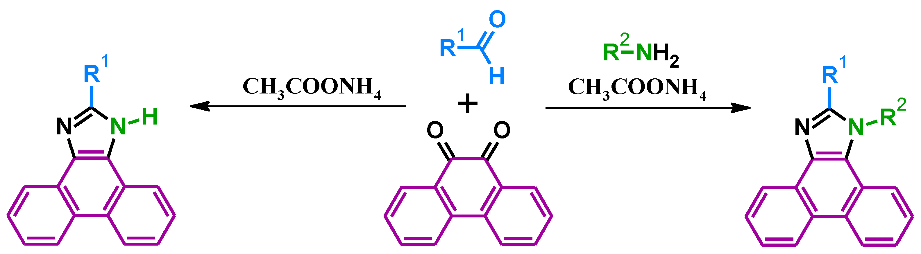
In the last two decades, interest in phenanthroimidazole derivatives has increased significantly [17,18,19,20,22,23,24,30,31,34,35,36,37,38,39,40,41,42,43,44,45,46,47,48,49,50]. From a synthetic aspect, compounds of this type are highly appreciated due to the simple and cheap method of obtaining them, which consists of the condensation of 9,10-phenanthrenequinone, aldehyde, ammonium acetate, and amine (Scheme 1) [17,18,19,20,22,23,24,30,31,34,35,36,37,38,39,40,41,42,43,44,45,46,47,48,49,50]. This type of reaction is often called the Debus–Radziszewski reaction in the literature [17,19,43,47]. As a result, an imidazole ring is formed, having substituents derived from the substrates. At the N1 position, there is a substituent from an amine, while in the C2 position, there is a substituent from an aldehyde. Aromatic rings derived from 9,10-phenanthrenequinone are attached to the imidazole ring at the C4 and C5 positions. Therefore, for a better understanding of the place of attachment of the aromatic fragment to the imidazole ring, the notation [9,10-d] (phenanthro[9,10-d]imidazole derivatives) is used in the nomenclature of phenanthroimidazole derivatives [35,40,41,43,45,47,49]. The letter d indicates the wall of the imidazole ring to which one of the phenanthrene rings is attached. Similarly, positions 9 and 10 refer to the corresponding position in phenanthrene. Moreover, this condensation reaction can be carried out without an amine [17,18,19,20,21,22,23,24,30,31,45,50]. This leads to phenanthroimidazole derivatives, which have only hydrogen (N-H) in the N1 position at the nitrogen atom [17,18,19,20,21,22,23,24,30,31,45,50].
The N-H group in the imidazole ring creates excellent opportunities for modifying the obtained derivatives, for example, using an alkylation reaction [17,19,20,21,22,23,24,30,31,34,35,36,37,38,39,40,41,42,43,44,45,46,47,48,49,50]. This is especially important in the case of the synthesis of compounds with low solubility.
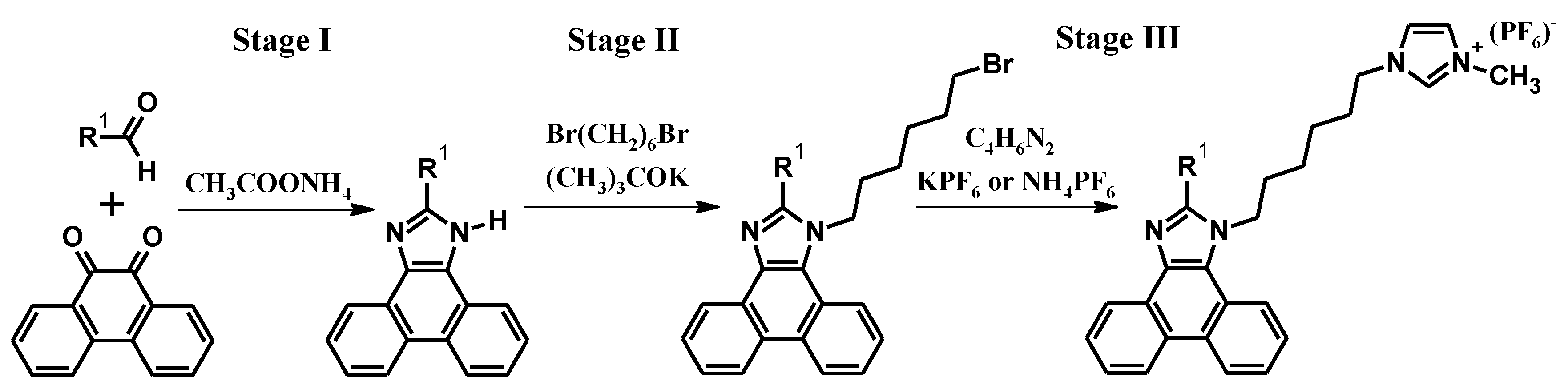
Phenanthroimidazole derivatives studied in the context of light-emitting electrochemical cells (LECs) are most often obtained in a three-stage synthesis (Scheme 2 and Scheme 3) [17,18,19,20,21,22,23,24,30,31]. However, this is not the case for all compounds described, as some have been prepared in fewer steps (PYPN, nbpypn, and nhpypn) [17,18,19,20,21,22,23,24,30,31].
The first stage of the synthesis consists of the condensation (Debus–Radziszewski reaction) of 9,10-phenanthrenequinone, aldehyde, and ammonium acetate (Scheme 2—stage I) [17,19,43,47]. The lack of an amine is intentional here since the phenanthroimidazole derivatives containing the N-H group can be further modified. The solvent used for this type of reaction is acetic acid. This is extremely advantageous since ammonium acetate and acetic acid can be easily removed from the reaction medium. It is enough to filter the precipitate of the product after the end of condensation and wash it thoroughly with water. An example of a phenanthroimidazole derivative obtained by condensation reaction is 2-(pyren-1-yl)-1H-phenanthro[9,10-d]-imidazole (PYPN). This compound, without further modification, has been investigated for use in light-emitting electrochemical cells [17]. An additional development of this step is the modification of the substituent at the C2 position in the imidazole ring. Suzuki coupling is most often used for this purpose, thanks to which the substituent can be extended with further aromatic or heteroaromatic fragments [20,21,22,23,24,30,31]. However, this requires a halogen atom (bromine or iodine) in the substituent at the C2 position. In addition, a suitable organoboron derivative is needed for the reaction. Suzuki coupling also requires a catalytic system based on palladium complex compounds. In the case of phenanthroimidazole derivatives, palladium catalyst as tetrakis(triphenylphosphine)palladium(0) ([Pd(PPh3)4]) and potassium carbonate (K2CO3) are most often used [20,21,22,23,24,30,31]. The most commonly used solvent system is a mixture of toluene, ethyl alcohol, and water (toluene/EtOH/H2O) [20,22,24] or tetrahydrofuran and water (THF/H2O) [30,31]. Interestingly, despite the many requirements, Suzuki coupling is a much more efficient solution than synthesizing the appropriate aldehydes. This is due to the limited solubility of aldehydes with extended substituents. In turn, low solubility can significantly reduce the efficiency of the condensation reaction. The following phenanthroimidazole derivatives were modified (concerning the substituent at the C2 position) via Suzuki coupling (Scheme 3): mPy, mAn, oPy, oAn, 1 (MCL), 2 (MCL), 1 (JPPCH), 2 (JPPCH), PhTz, C1, C2, PITT, PITP, and PBT [20,21,22,23,24,30,31]. The second step consists of the alkylation of the considered compounds (Scheme 2—stage II) [18,19,20,21,22,23,24,30,31]. Most often, an excess of 1,6-dibromohexane is used for this reaction. This makes obtaining phenanthroimidazole derivatives containing an alkyl chain terminated with a bromine atom in the N1 position (in the imidazole ring) possible. This type of alkylation is carried out in the presence of potassium tert-butoxide ((CH3)3COK) and tetrahydrofuran (THF) as a solvent [18,19,20,21,22,23,24,30,31]. The bromine atom in the alkyl chain is essential as it allows the next reaction in step three to proceed. The length of the alkyl chain used for the reaction is very important. Too short a chain significantly reduces the solubility of the final compounds in organic solvents and causes synthetic difficulties [18]. An example of such a compound is the ihpypn derivative [18]. In addition, two phenanthroimidazole derivatives having alkyl chains without additional substituents or functional groups have been described in the literature, which have also been investigated in terms of light-emitting electrochemical cells [18]. These compounds are 1-hexyl-2-(pyren-1-yl)-1H-phenanthro[9,10-d]imidazole (nhpypn) and 1-butyl-2-(pyren-1-yl)-1H-phenanthro[9,10-d]imidazole (nbpypn). These derivatives were also obtained by using an alkylation reaction; however, different reaction conditions were used [18]. The third stage consists of the reaction of previously obtained phenanthroimidazole derivatives with 1-methylimidazole (Scheme 3—stage III) [16,17,18,19,20,21,22,23,30]. Interestingly, this step does not require the use of a solvent. 1-Methylimidazole acts as both a substrate and a solvent. After the reaction is completed, potassium hexafluorophosphate (KPF6) [18] or ammonium hexafluorophosphate (NH4PF6) is added to the post-reaction mixture, directly or in the form of an aqueous solution [19,20,21,22,23,24,30,31]. The precipitate is then washed with water, ether and dried under vacuum [19,20,21,22,23,24,30,31]. It is worth emphasizing that through this three-step synthesis, many phenanthroimidazole derivatives presented in the Scheme 3 were successfully obtained. In conclusion, phenanthroimidazole derivatives can be obtained by using a simple and cheap condensation reaction. Many of these halogen (bromine or iodine) compounds can be modified by using coupling reactions (e.g., Suzuki or Buchwald–Hartwig). Moreover, derivatives that do not have a substituent on the nitrogen atom at the N1 position (on the central imidazole ring) can be alkylated. This allows us to introduce an alkyl chain into the structure, which increases solubility. In addition, alkyl chains containing an additional bromine atom can be extended with heteroaromatic fragments (e.g., 1-methylimidazoles). This makes it possible to change the nature of the molecule from neutral to ionic. Due to the many possibilities of structural modifications, phenanthroimidazole derivatives are characterized by good solubility and processability, high stability, excellent electron transport ability, easy-to-achieve ionization, and favorable optical and electroluminescent properties.
3. Thermal Properties
Research on thermal properties is one of the essential elements enabling the evaluation of organic compounds in terms of their use in light-emitting electrochemical cells (LECs). Devices based on the phenomenon of electroluminescence can generate heat due to the Joule heating effect [23,24,30,31]. Therefore, the thermal stability of the tested compounds is crucial. First of all, it directly impacts the morphological stability of the thin layer in the device. In addition, the low thermal stability of the materials used may change the device’s parameters during its operation or even lead to permanent damage.
The thermal properties of the phenanthroimidazole derivatives discussed in this paper (Scheme 3) were investigated using differential scanning calorimetry (DSC) and thermogravimetric analysis (TGA) [18,19,20,21,22,23,24,30,31]. All results described in the literature are presented in Table 1. Interestingly, phenanthroimidazole derivatives are generally characterized by high thermal stability. This is primarily due to the properties of the molecule’s core [50]. In the case of the presented derivatives, a 5% weight loss (Td) is observed in the range of 335–426 °C. This proves the very high thermal stability of the considered compounds. Introducing a substituent containing an alkyl chain at the N1 position (in the imidazole ring) causes a slight decrease in stability. In turn, introducing a substituent with multiple aromatic rings in the C2 position benefits thermal properties [18]. An example of a group of phenanthroimidazole derivatives, the thermal properties of which perfectly demonstrate the described relationships, are compounds with pyrene in the C2 substituent [18]. The discussed derivatives’ glass transition temperatures (Tg) range from 99 to 190 °C. Such high Tg values are very advantageous in terms of the use of phenanthroimidazole derivatives in devices based on the phenomenon of electroluminescence. Only PYPN [17] and nbpypn [18] compounds show a melting point (Tm) (Figure 1).
4. Redox Behavior
Another important element enabling the evaluation of organic materials are electrochemical tests. They answer how the obtained chemical compound will behave under the influence of the applied voltage. These studies experimentally allow us to determine such values as ionization potential, electron affinity, and energy gap. These values correspond to the HOMO and LUMO values. An additional advantage of these tests is the information on the reversibility of processes occurring in the measurement environment. As it is known, for an organic compound to be ideal, it should undergo reversible oxidation and reduction. This is because in operating LEC devices, n-doping occurs at the cathode, and p-doping occurs at the anode, resulting in a p-n junction [23,31]. Given the above information, it was decided to analyze the electrochemical studies of the discussed group of phenanthroimidazole derivatives. All data described in the literature are presented in Table 2.
Electrochemical tests were performed by using cyclic voltammetry [17,18,19,20,21,22,23,24,30,31]. The most commonly used but not the only solvent was acetonitrile [21,22,23,24]. In addition, dichloromethane [17], DMSO [19] and DMF:ACN (50:50) [20] were used as the measurement environment. Ferrocene is often used as an internal standard [17,18,19,20,21,22,23]. Tetrabutylammonium hexafluorophosphate was used as the electrolyte [17,18,19,20,21,22,23,24,30,31]. The concentration of the measured samples was 10−3 M. The measurements were carried out in a three-electrode system. The working electrode was platinum [16,20,21,22,23] or glassy carbon [17,19,20]. Platinum wire was the counter electrode and Ag/AgCl was used as the reference electrode [17,18,19,20,21,22,23,24,30,31]. The tests were carried out at room temperature with a standard scan rate of 100 mV/s [21,22,23,24,30,31] or 50 mV/s [17,19,20].
The first of a series of electrochemically measured compounds described was PYPN. Its structure includes phenanthroimidazoles (the molecule’s core) and pyrene (substituent at the C2 position). In 2015, M. Subeesh et al. showed that it undergoes an oxidation process at 0.99 V [17]. These data allowed them to determine the HOMO value from the following formula: EHOMO = −4.32 − Eonset (Ox). The authors calculated the LUMO value using the obtained optical gap value and HOMO [17]. However, no information is given on the measurements of the reduction process. Interestingly, research was carried out in the same year on the compounds nhpypn, nbpypn, ihpypn, and ibpypn. Unfortunately, these molecules have not been tested electrochemically [18]. A year later, the same group included ihpypn in their research, presenting electrochemical results [19]. In 2017, research on the group of compounds mPy, oPy, mAn, and oAn gave a lot of interesting information [20]. The first of them concerned the HOMO and LUMO values (Table 2). For the first time, these values were calculated using data on reduction and oxidation onsets. In this case, the following formulas were used: EHOMO = −4.34 − Eonset (Ox) and EHOMO = −4.34 − Eonset (red) [20]. In addition, the issue of reversibility of processes was raised. All molecules showed reversible reduction peaks, while oxidation was poorly reversible. The authors noted, however, that mPy presented a partially reversible oxidation peak, which classifies it as the best compound for LEC compared to the rest (oPy, mAn, and oAn) [20]. In 2019, researchers again changed the method of determining the HOMO value. As before, the oxidation onset was used for the calculations, but the formula, EHOMO = −(Eonset (Ox) + 4.40), was used [22]. It would seem that it is generally the same, but the obtained results differ by 0.08 eV compared to the results from 2015 (Table 2). The PhTz compound was interesting in the analysis, showing a quasi-reversible oxidation peak. It was noted that this indicates the required p-type doping capacity [23]. J. John et al., in 2020, presented research on compounds C1 and C2 [24]. This article presented the voltammograms of the oxidation and reduction processes, although the values of onsets from the reduction process were not shown [24]. Interestingly, the authors indicated a slight mismatch between the electrochemical bandgap and the optical bandgap. This may be due to impurities in the tested compounds resulting from the redox properties. Due to these electrochemical stability issues, the stability of the devices was reduced for repeated JVLs. In 2021, tests were carried out for PITP and PITT, determining HOMO and LUMO for them [30]. The authors concluded that higher PITT energy levels imply a lower turn-on voltage than in PITP-based devices. The appropriate frontier orbital energy levels of both compounds indicate effective charge injection and recombination to improve the device performance of non-doped LECs [30]. Summing up the previous electrochemical studies, it can be concluded that the oxidation potential for the presented group of compounds is in the range of 0.68 V to 1.26 V. The values of the HOMO orbital (despite the differences in its determination) are in the range from −5.08 eV to −5.66 eV. For LUMO, the values range from −2.00 eV to −3.59 eV. The LUMO values were determined using the optical gap or reduction potential onset.
5. DFT Calculations
A very important part of scientific research is theoretical considerations based on calculations. They help to understand the occurring phenomena. Thanks to the DFT calculations, we can determine the position of the HOMO and LUMO orbitals along with their values and energy gap. In addition, we can simulate absorption plots, determine bond lengths and angles in molecules, and many other vital parameters. It is worth remembering, however, that all results depend on the selection of computational conditions and should constantly be confronted with experimental results. To better understand the electronic properties of the discussed molecules, density functional theory (DFT) and time-dependent density functional theory (TDDFT) calculations were carried out. The most frequently used functional was B3LYP [18,19,23]. Functionals, such as CAM-B3LYP5 [19] or BP86 [24,31], were also used for the calculations. Among the bases, 6–31 G (d) [18,19] and triple-ζdef2-TZVP [24,31] can be distinguished. All calculation results described in the literature are presented in Table 3.
In 2015, M. Subeesh et al. presented the HOMO and LUMO values for the compounds nhpypn, nbpypn, ihpypn, and ibpypn [18]. The authors performed calculations of molecules in neutral form without considering the ionic side groups. At the same time, they assumed that the prediction of HOMO energy distribution for compounds with such groups might be regarded as unreliable. Due to the same structure of the neutral form (core and substituent in the C2 position—pyrene) for all phenanthroimidazole derivatives, the values of the frontier molecular orbitals obtained are the same (Table 3). In the case of orbital distribution, it can be observed that HOMO energy levels occupy the entire core, while LUMO is limited to the pyrene group [18]. Moreover, the dihedral angles between the phenanthroimidazole core and the C2 substituted pyrene were shown to be 61.17°, 61.33°, 61.28°, and 61.36° for nhpypn, nbpypn, ihpypn, and ibpypn, respectively. In addition, it was observed that this angle slightly increases with the decrease in the length of the alkyl chains. According to DFT calculations, the ionic molecule with a hexyl bridge (ihpypn) is the most stable, and stability decreases with decreasing alkyl chain length [18]. A year later (2016), more advanced theoretical research on ibpbn and itpbn derivatives was conducted. In addition, the ihpypn compound was recalculated [19]. The same assumptions were made for the considered derivatives as in the previous year. Additionally, absorption and emission spectra were calculated (Figure 2).
It has been shown that itpbn has adopted a very twisted configuration. Along with the ionic side chain, this twisted structure of itpbn may reduce intermolecular interactions in the solid state [19]. Intermolecular interactions are unfavorable in electroluminescent devices due to aggregation-induced fluorescence quenching in the solid state. In contrast, parent materials with controlled intermolecular interactions are attractive for regulating charge transport in the active layer of LEC devices. However, the ibpbn relationship deserves attention [19]. It has the HOMO orbital located mainly on the phenanthroimidazole (donor), while the LUMO is primarily situated on the benzothiadiazole (acceptor) and acetylene bridges. This results in optimal overlapping of the frontier molecular orbitals in that molecule. The acceptor and phenyl π bridge are positioned nearly planar in this molecule due to the ethylene bridge, which decreases steric hindrance between peripheral hydrogen atoms [19]. The dihedral angle between the donor phenanthroimidazole and the π bridge was calculated to be 31°. This fact shows that the excited-state CT dominates in the molecule [19]. The discussed compounds’ (ibpbn, itpbn, and ihpypn) energy gaps for singlet and triplet states were also calculated. They are 2.12, 3.58, and 3.17 eV for S1 and 1.44, 2.79, and 2.06 eV for T1 for ibpbn, itpbn, and ihpypn, respectively [19]. The obtained data are presented in Table 3. Subsequently, important theoretical data were obtained for the mPy, oPy, mAn, and oAn compounds [20]. As could be expected for mPy and oPy compounds, the distribution of HOMO and LUMO orbitals is the same as for structurally similar compounds. HOMO covers the molecule’s core (phenanthroimidazole), while LUMO is on the substituent at the C2 position (pyrene) [20]. A more interesting and not obvious result concerns mAn and oAn. In their case, both orbitals are located only on the anthracene substituent. Indeed, the authors did not present the values of the HOMO and LUMO orbitals, although determining their location gives interesting information [20]. By analyzing the dihedral angles, we see that they increase for ortho molecules. This is due to increased steric hindrance. Highly twisted molecular orientations of oAn or oPy molecules may make them good LEC emitters due to the low intermolecular interactions of these molecules in the solid state [20]. More advanced theoretical studies have been conducted for PhTz [23]. As a result, it was shown that the LUMO orbital is located mainly on the diphenyl triazine unit, which is electronegative in nature [23]. In addition, it includes a phenyl linker between the substituent and the molecule’s core. The HOMO orbital, as in the previously described derivatives, is located on the phenanthroimidazole core. A good overlap of both orbitals has been shown. The partial segregation of the LUMO and HOMO may be helpful for reducing the dipolar quenching of fluorescence in its thin-film state [23]. Singlet (S1) and triplet (T1) excited-state values were calculated for PhTz [23]. They were 2.93 eV and 2.57 eV for S1 and T1, respectively. The gap energy (ΔEST) between these states was 0.36. A large value of ΔEST may be related to poor HOMO and LUMO separation. The authors concluded that the compound could not be a TADF material. This is due to the fact that such materials have small values of ΔEST [23]. In 2020, for compounds C1 and C2, it was decided to use a different functional and basis for geometry optimization. HOMO, LUMO, and absorption spectra calculations were performed. A good agreement between the obtained results and the experimental results was found [24]. In 2021, K. Shanmugasundaram et al. presented two compounds of similar structure—PITP and PITT [30]. Common elements for both derivatives were the phenanthroimidazole core, the substituent in the N1 position, and the thiophene linker in the C2 substituent. PITP additionally contained pyrene, while in PITT, the substituent attached to thiophene was triphenylamine [30]. Thanks to the performed calculations, it was shown that both groups (pyrene and triphenylamine) could form a great bridge that improves electronic interactions between the segments due to the delocalized HOMO orbital along the conjugated backbone. In addition, the participation of the nitrogen atom in the triphenylamine group increased the HOMO and LUMO energy levels by 0.17 eV and 0.08 eV, respectively, in relation to the molecule with pyrene. The theoretical calculation results of both PITP and PITT indicate favorable characteristics for constructing efficient light-emitting devices [30]. In conclusion, in most of the results presented in the literature, the authors focused on calculations for molecules in a neutral form without taking into account ionic side groups. Moreover, they determined many necessary parameters, such as HOMO, LUMO, and absorption wavelengths. The value of the HOMO orbital ranged from −5.16 eV to −7.00 eV, and the LUMO orbital between −1.37 eV and −5.56 eV.
6. Optical Properties
Research on the absorption and emission of organic compounds is the basis for research on potential emitters for electroluminescent devices. Thanks to them, we can determine the bands’ maxima and the considered compounds’ lifetimes and quantum yields. In addition, these studies allow us to check the solubility and behavior of the molecule in solvents of different polarities. Additionally, these properties can be determined in solids. In the case of the presented phenanthroimidazole derivatives, the study of optical properties began with measuring the absorption and emission spectra. The concentration of the measured samples was 10−5 M [17,21] or 10−3 M [31]. The measurements were recorded in solvents such as anhydrous tetrahydrofuran [17,30,31], acetonitrile [21], etc. The solution photoluminescence quantum yield measurements (PLQYs) were measured in dichloromethane [17] or anhydrous tetrahydrofuran [18] (10−7 M) with diphenyl anthracene as standard (ΦF = 0.9 in cyclohexane). Thin films for PL measurements were prepared by spin coating the corresponding solution onto glass substrates [17,18,19,20,21,22,23,24,30,31]. All test results described in the literature are presented in Table 4.
The first of the compounds tested was PYPN [17]. Two bands were registered in the absorption spectra. The first, with a maximum of about 260 nm, was intense and characteristic of phenanthroimidazole derivatives. The second turned out to be broad and less intense. The authors attributed this to the delocalized p-p* transition of phenanthroimidazole [17]. They then determined the values of λPL, photoluminescence quantum yield for a solution and thin film, and the optical gap. Thanks to the obtained data, a Stock shift of 77 nm was determined. Subsequently, the measurements of the emission of the compound in a thin solid layer were carried out. It was found that the λPL of PYPN in the layer was redshifted by 19 nm in relation to the solution. This was 477 nm [17]. The layer was then subjected to annealing at 120 °C for 1 h. A further redshift of about 3 nm from the unannealed thin-film emission was observed. M. Subeesh et al. found that strong intermolecular interactions in the solid state could explain this phenomenon. Moreover, to eliminate this problem, alkyl spacers or aliphatic bulky groups at the N1 position should be added [17]. In 2015, researchers assumed that solubility is an important feature of the considered organic compounds. Therefore, the nhpypn, nbpypn, ihpypn, and ibpypn derivatives were tested using a series of solvents with different polarities [18]. It has been shown that the solubility in organic solvents increases with the growth of the alkyl chain, regardless of the polarity of the solvents used. The neutral molecules had good solubility in THF and DMF [18]. On the other hand, ionic compounds were more soluble in typical organic solvents, especially in acetonitrile. This fact makes them attractive because the production of acetonitrile thin films is simple [18]. Interestingly, for all presented derivatives (nhpypn, nbpypn, ihpypn, and ibpypn), the same absorption values were obtained [18]. The reason for this is the same core and substituent (at the C2 position) for all molecules. The absorption spectra of these derivatives can be divided into two areas. The first band shows a typical phenanthroimidazole derivative characteristic of the intense band from 312 to 360 nm. This band can be attributed to the delocalized π–π* transition of the phenanthroimidazole core. The second region from ~250 to 300 nm may be derived from a combination of π–π* transitions of aromatic segments [18]. However, emission studies showed that all molecules exhibited intense blue fluorescence in thin film processed in solution. Moreover, the different alkyl chains do not have much influence on the photoluminescence behavior of these emitters in solutions. For the presented group, it was noticed that the thin-film emission for ionic compounds is less redshifted relative to the solution than for neutral compounds [18]. Ionic compounds have a lower tendency to aggregate than neutral derivatives. The PLQY in the thin film for ionic derivatives is higher, underlining the observation that ionic side chains effectively reduce molecular aggregation in this type of molecules and thus reduce aggregation-induced fluorescence quenching in the solid states [18]. In 2016, it was shown that compounds with the same core show similarity in terms of absorption properties (Figure 3) [19]. In addition, the absorption and emission spectra for structurally similar compounds (itpbn and ihpypn) showed a slight change in the position of the band from tetrahydrofuran to acetonitrile, suggesting that these molecules have a slight dipolar change in ground and excited states in polar solvents. The authors concluded that this might be due to the weaker charge-transfer (CT) character of excited states in the molecules, and the energy level responsible for the radiative transition is the locally excited state (LE) [19]. The compound ibpbn turned out to be interesting in the analysis. In the absorption spectrum, π–π* bands of phenanthroimidazole derivatives were observed for it, as well as a typical low-energy broad CT peak at 421 nm.
The emission maximum for acetonitrile was 506 nm [19]. On the other hand, the spectrum in dichloromethane had rather two maximum peaks, which may suggest an equal contribution from the excited states of LE and CT. A shift towards longer wavelengths (hexane, 591 nm) was observed in less polar solvents. This may be due to more productive relaxation from low-lying CT excited states, which are less stabilized by neutral solvent molecules at this state. The authors concluded that a dominant low-lying CT state exists in this molecule, which is stabilized by solvent dipoles in the highly polar environment, causing nonradiative relaxation from CT excited states. On the other hand, in neutral solvents, the CT state becomes the dominant channel for emission [19]. Taking into account the fluorescence quantum yield, it decreased from 0.3 in toluene (489 nm) to 0.002 (506 nm) in acetonitrile for the discussed derivative. Ibpbn was also measured in the thin layer [19]. The emission maximum was 583 nm (sharp peak) at 292 nm excitation. M. Subeesh et al., however, indicate that the excitation wavelength is exactly half of the emission peak. The observed signal may be due to a harmonic of the excitation source rather than lasing action of this dye in thin film [19]. Although the authors tested the compounds in question in more solvents, they only provided full data for acetonitrile. The group of mPy, oPy, mAn, and oAn compounds turned out to be extremely interesting for research [20]. oAn was poorly soluble in organic solvents. Therefore, it was not tested. Moreover, oPy also had low solubility in contrast to meta-substituted derivatives. An important observation, however, is that neither ortho nor meta substitution affected the absorption band. For compounds mPy and oPy, these spectra were similar [20]. Emission spectra for the presented derivatives were measured in four solvents of different polarities (hexane, ether, THF, and acetonitrile). The mPy compound exhibited typical charge transfer excited-state characteristics. In acetonitrile, the emission consisted of a band with a maximum of about 381 nm and an arm with a maximum of about 494 nm. In addition, a less intense low-energy broad, typical charge transfer emission was observed that appeared like a tailing of the shoulder peak at 397 nm [20]. The high energy emission of acetonitrile can be attributed to relaxation from the LE state. A very similar emission has already been described in the literature for the PPI unit. The emission in the thin layer was similar to solutions of low polarity and was 449 nm. The emission properties were similar in the case of oPy and oAn molecules. oPy behaved in the opposite way to mPy. Apart from acetonitrile (19 nm shift from hexane), it showed no significant wavelength shift in solvents of different polarities. In the case of thin layers, oPy and oAn derivatives behaved similarly, and their emission spectra shifted slightly relative to hexane. Unfortunately, the authors did not provide the exact data from tests carried out in solvents of different polarities [19]. In 2019, J. Park et al. presented the possibility of using the phenomenon of aggregation-induced emission for LEC cells [22]. They successfully determined the absorption values for the obtained derivatives. As in the case of previous compounds, the obtained bands were assigned to the π−π* transition of the molecule’s core. The authors found that tetraphenylethylene (TPE) derivatives are almost non-fluorescent in solution but show strong emissions when aggregated. Therefore, for compounds 1 (JPPCH) and 2 (JPPCH), absorption and emission measurements were performed in a THF/water mixture. Interestingly, both compounds showed a similar trend. When the water fraction reached 90%, the derivatives showed emission of blue light at 472 nm and 474 nm for 1 (JPPCH) and 2 (JPPCH), respectively [22]. Both the compounds were AIE-active due to the suppressed intramolecular rotation in the aggregated state, which, consequently, blocked the non-radiative relaxation of the excited state. As in structurally similar compounds, PhTz showed absorption in two regions [23]. The first one in the 260–270 nm range corresponds to the π−π* transitions of the molecule’s core. The second one, between 330 and 400 nm, corresponds to the intramolecular charge (ICT) from the electron-donating phenanthroimidazole core to the electron-withdrawing triazine group [23]. The emission spectrum recorded for this compound was broad and slightly redshifted, indicating intermolecular interaction and forming a compact stacking structure in the solid state. For PITP and PITT derivatives, the emission was measured in solvents of increasing polarity [30]. It has been observed that along with the increase in the solvent polarity, gradually widened and less pronounced redshifts were observed in the PL spectra, which suggest that their excited states have a negligible charge transfer character [30]. Interestingly, for the PBT compound, in addition to the standard UV-Vis in solution, the authors also tested UV-Vis in a thin layer [31]. As expected, a bathochromic shift in the absorption peak was observed. This resulted from intermolecular interactions in a thin-film state [31]. Summing up the previous studies, it can be concluded that all phenanthroimidazole derivatives presented so far showed similarities in absorption spectra. For all compounds, these spectra were attributed to transitions within the phenanthroimidazole core. Moreover, the choice of solvent had no effect on it. In turn, the emission was measured in solvents of different polarities, but not all result values were presented. The emission maximum in the solution ranged from 381 nm to 619 nm. The tests in thin layers also turned out to be important because they were similar in nature to later application tests in test devices.
7. Electroluminescence Properties and Device Characterization
The basis of all research is the pursuit of scientific progress. In this case, the important element was to obtain a well-functioning LEC device. Due to their simple design, light-emitting electrochemical cells are a great alternative to the currently researched OLEDs. The LEC design is based on several layers. Most often, the architecture of the device is designed as follows: ITO/PEDOT:PSS/active layer/Al [17,18,19,20,21,22,23,24,30,31]. In the selected examples, it was possible to find exact data on the thickness of individual layers. The following details were used: ITO/PEDOT:PSS (80 nm)/active layer (90 nm)/Al (100 nm) [17], ITO/PEDOT:PSS (40 nm)/active material (70 nm)/Al (100 nm) [31], or ITO/PEDOT:PSS (80 nm)/active layer (60 nm)/Al (100 nm) [20]. These layers were applied one after the other by using the spin-coating method. Each layer was properly annealed before applying the next one [17,18,19,20,21,22,23,24,30,31]. The active layers contained the target chemicals. Neutral and ionic molecules were most often used for research. Ionic compounds were used directly while neutral compounds were mixed with ion-transporting polymers and inorganic salts [18]. All obtained data are summarized in Table 5.
The first phenanthroimidazole derivative tested in an LEC device was PYPN. The active layer made of this compound was ternary. It contained in its structure PYPN, polyethylene oxide, and lithium triflate in a weight ratio of 1:0.1:0.185 (PYPN:PEO:LiCF3SO3) [17]. The recorded electroluminescence spectrum for PYPN gave a yellow–green emission of 521 nm. This study observed that this spectrum was redshifted relative to the photoluminescence spectra in solution. Interestingly, the EL spectrum was more redshifted than the PL spectra in the thin layer (as-spun film and annealed film). M.S. Subeesh et al. found that this phenomenon is not related to the LEC mechanism but depends on the presence of lithium triflate. The PL spectra recorded for heat-treated thin films containing lithium triflate are similar to the EL emission. This may be due to the replacement of inert solvent molecules by ions in the solid state [17]. The device itself exhibits typical LEC behavior with delayed turn-on voltage. This is evidenced by the initial difficulty of charge injection and the slow movement of ions in the active layer, followed by rapid growth. The PYPN molecule has a good charge transport character, which can be seen in the J-V curve [17]. However, this compound is characterized by low luminosity at high current density. This indicates a strong tendency to aggregate in the solid state. In the same year, research was conducted on nhpypn, nbpypn, ihpypn, and ibpypn compounds [18]. In devices based on nbpypn and nhpypn compounds, the active layer was prepared as in the case of PYPN. In contrast, ionic compounds were used without additional components. All devices reported sky-blue emissions and redshifts relative to thin-film PL spectra [18]. Interestingly, the ionic molecules had smaller shifts than the neutral compounds. On the other hand, ionic compounds show the best CIE blue coordinates. The authors noted that the neutral compounds have similar emission shifts as the parent molecule. In addition, introducing a short alkyl chain in the nbpypn derivative makes the EL properties of this compound similar to those of PYPN. This indicates that the length of the alkyl chain connected to the N1 nitrogen in the imidazole ring affects the performance of phenanthroimidazole derivatives in the LEC cell [18]. Ihpypn and ibpypn were characterized by a high value of maximum brightness. Neutral derivatives do not impress in the context of maximum brightness, especially the derivative with a butyl chain (at the N1 position) (nbpypn), which showed poor results [18]. Weak electroluminescence of neutral molecules can be caused by the improper formation of doping areas in their active layers or fluorescence quenching caused by intermolecular interactions in the emissive layer. M. Subeesh et al., analyzing the overall performance of the device, found that simple alkyl chains in neutral compounds are not sufficient to inhibit intermolecular interactions in the solid state. Moreover, the incorporation of ionic fragment side chains into phenanthroimidazole derivatives seems to be a better way to generate improved solution-processable emitters for LECs [18]. M. S. Subeesh et al., looking for more efficient devices, decided to change the active layer. For LECs with ihpypn, ibpbn, and itpbn compounds, host–guest blends with different dopant contents were used (Table 5). For the first four devices based on the ihpypn (host) construct: ibpbn (dopant), it was observed that most of the emissions came from ibpbn. The shoulder to its left, corresponding to host emissions, is visible [19]. Moreover, the emission intensity of the host decreases as the amount of dopant increases. This clearly indicates increased energy transfer from the host to the admixture. By analyzing the CIE coordinates, we can see that the parameters of the devices shift from the blue–green to the green spectral region, depending on the amount of impurity. Noteworthy here is device 2 because it is characterized by high efficiency with reasonable brightness [19]. This shows that a low emitter concentration in the active layer can be used to obtain efficient and bright LEC devices based on D−A emission. M. S. Subeesh et al. also tested the reverse guest-to-host energy transfer approach. Itpbn was the host, and ibpbn was the emitting component [19]. Devices based on this design were characterized by poor electroluminescence results. In addition, emission from host molecules was also recorded. In contrast, the CIE coordinates shifted towards the white area. The authors noted that devices containing itpbn in their structure show clear fluctuations in current density with increasing voltage. In addition, the I−V−L characteristics of these electrochemical cells show that charge transport through the active itpbn layer is not an easy process (Figure 4) [19].
In 2017, the impact of the substitution position on the possibility of using compounds in LEC devices was studied. These studies were carried out on the group of mPy, mAn, oPy, and oAn compounds [20]. Due to the poor solubility of oPy and oAn compounds, they could not be used to construct LEC. First, mPy and mAn were tested as components of the active layer. Devices based on these molecules exhibited blue electroluminescence with peak luminosities of 179 (mPy) and 26 (mAn) cd/m2 [20]. Preliminary studies have shown that single-component devices alone produce insufficient results. Therefore, mPy, which showed better performance, was selected to investigate whether the electroluminescence performance could be improved with additional ions. Three new devices were produced with the active ingredient mPy, together with polyethylene oxide and lithium triflate [20]. As a result, the properties of the new LECs improved significantly (see Table 5). In addition, in order to test the possibility of converting mAn into a better emitter, an LEC was constructed with mAn, polyethylene oxide, and lithium triflate at a ratio of 1:0.1:0.1. In this case, the parameters improved as well [20]. Although the ternary mPy devices had better device characteristics, the mAn compound in the mixture presented the best blue EL emission (459 nm, CIE (0.166, 0.173)) [20]. In 2019, phenanthroimidazole derivatives with AIE character were tested in undoped LEC devices. Both compounds (1 (JPPCH) and 2 (JPPCH)) exhibited blue-light emission that was not different from their thin-film photoluminescence spectra [22]. It can be concluded that the AIE nature of both compounds shows similar thin-film emission without any spectral shift in the EL spectrum. Interestingly, the authors determined the external quantum efficiency for the first time, which was 2.63% and 2.95% for compounds 1 (JPPCH) and 2 (JPPCH), respectively [22]. Further attempts to obtain better and better devices led to A. Puthanveedu et al. obtaining an undoped device with PhTz in the active layer [23]. It is worth noting that the CIEx for this molecule is marked closer to the pure-green color coordinates specified by the NTSC as 0.21, 0.71. In the following years, the research focused on the blue color as well as improving the current parameters of LEC devices [23]. Through research on PITP and PITT compounds, the authors concluded that the efficiency and luminance of LEC devices could be improved by designing emitters with different connectors with different electron transport capacities [30]. In 2022, a device made of PBT was obtained, which showed an electroluminescence peak of 622 nm with a distinct orange–red emission [31]. The devices fabricated have been characterized for various particulars like current density, current efficiency, power efficiency, external quantum yield, etc. (Table 5). Summing up the previous research, it can be concluded that most of the phenanthroimidazole derivatives used in the active layer gave blue EL emission. The maximum luminance ranged from 26 to 5016 cd/m2. Tested devices were characterized by low turn-on voltages below 11 V. Single-component as well as multi-component devices were used for the tests.
8. Conclusions
Light-emitting electrochemical cells (LECs) are a promising alternative to the currently researched and used light sources. Significant progress has been made in studying LECs over the past three decades. In the case of the active layer, using ionic transition-metal complexes (iTMCs) and conjugated polymers (CPs) improved the parameters of the devices. However, rising metal prices and dwindling iridium deposits may significantly limit the use of iTMC. On the other hand, the use of CP is largely limited due to a long and expensive synthesis and a structure that is difficult to confirm unambiguously. Therefore, research on small molecules (SMs) is an extremely important direction for the further development of LECs. It is worth emphasizing that the design of new emitters based on the phenanthroimidazole core has great potential. First, by selecting the appropriate substituent at the C2 position (in the central imidazole ring), we can fine-tune the physicochemical properties of the final molecule. In addition, by modifying the N1 (N-H) position, we can introduce an ionic fragment into the structure of the compound. Both substituents (C2 and N1) can successfully contain alkyl chains that will increase solubility, which is very important in the case of LECs. Moreover, the phenanthroimidazole core can also be expanded with further substituents that improve the properties.
Author Contributions
Conceptualization, A.S.-K. and S.K.; methodology, A.S.-K. and S.K.; data curation, A.S.-K. and S.K.; writing—original draft preparation, A.S.-K. and S.K.; writing—review and editing, A.S.-K. and S.K.; visualization, A.S.-K. and S.K.; supervision, A.S.-K. and S.K. All authors have read and agreed to the published version of the manuscript.
Funding
This research received no external funding.
Data Availability Statement
Data sharing is not applicable to this article.
Conflicts of Interest
The authors declare no conflict of interest.
References
- Sayed, E.T.; Olabi, A.G.; Alami, A.H.; Radwan, A.; Mdallal, A.; Rezk, A.; Abdelkareem, M.A. Renewable Energy and Energy Storage Systems. Energies 2023, 16, 1415. [Google Scholar] [CrossRef]
- Sha, M.-Z.; Pu, Y.-J.; Yin, H.; Hao, X.-T. Recent Progress of Indoor Organic Photovoltaics—From Device Performance to Multifunctional Applications. Org. Electron. 2023, 114, 106736. [Google Scholar] [CrossRef]
- Jin, J.; Wang, Q.; Ma, K.; Shen, W.; Belfiore, L.A.; Bao, X.; Tang, J. Recent Developments of Polymer Solar Cells with Photovoltaic Performance over 17%. Adv. Funct. Mater. 2023, 33, 2213324. [Google Scholar] [CrossRef]
- Xie, Y.; Lu, H.; Huang, J.; Xie, H. Natural Materials for Sustainable Organic Solar Cells: Status and Challenge. Adv. Funct. Mater. 2023, 33, 2213910. [Google Scholar] [CrossRef]
- Solak, E.K.; Irmak, E. Advances in Organic Photovoltaic Cells: A Comprehensive Review of Materials, Technologies, and Performance. RSC Adv. 2023, 13, 12244–12269. [Google Scholar] [CrossRef] [PubMed]
- Fara, L.; Chilibon, I.; Craciunescu, D.; Diaconu, A.; Fara, S. Review: Heterojunction Tandem Solar Cells on Si-Based Metal Oxides. Energies 2023, 16, 3033. [Google Scholar] [CrossRef]
- Mohamed El Amine, B.; Zhou, Y.; Li, H.; Wang, Q.; Xi, J.; Zhao, C. Latest Updates of Single-Junction Organic Solar Cells up to 20% Efficiency. Energies 2023, 16, 3895. [Google Scholar] [CrossRef]
- Tarique, W.B.; Uddin, A. A Review of Progress and Challenges in the Research Developments on Organic Solar Cells. Mater. Sci. Semicond. Process. 2023, 163, 107541. [Google Scholar] [CrossRef]
- Ahmad, N.; Liang, G.; Fan, P.; Zhou, H. Anode Interfacial Modification for Non-Fullerene Polymer Solar Cells: Recent Advances and Prospects. Infomat 2022, 4, e12370. [Google Scholar] [CrossRef]
- Woo, J.Y.; Park, M.; Jeong, S.; Kim, Y.; Kim, B.; Lee, T.; Han, T. Advances in Solution-Processed OLEDs and Their Prospects for Use in Displays. Adv. Mater. 2023, 34, 2207454. [Google Scholar] [CrossRef]
- Miao, W.; Hsiao, F.; Sheng, Y.; Lee, T.; Hong, Y.; Tsai, C.; Chen, H.; Liu, Z.; Lin, C.; Chung, R.; et al. Microdisplays: Mini-LED, Micro-OLED, and Micro-LED. Adv. Opt. Mater. 2023, 11, 2300112. [Google Scholar] [CrossRef]
- Zeng, X.-Y.; Tang, Y.-Q.; Cai, X.-Y.; Tang, J.-X.; Li, Y.-Q. Solution-Processed OLEDs for Printing Displays. Mater. Chem. Front. 2023, 7, 1166–1196. [Google Scholar] [CrossRef]
- Zuo, P.; Qu, Y.-K.; Zheng, Q.; Liao, L.-S.; Jiang, Z.-Q. Sensitized Organic Light-Emitting Diodes: Towards High Efficiency and Long Lifetimes. Mater. Chem. Front. 2023, 7, 1760–1780. [Google Scholar] [CrossRef]
- Zhou, Z.; Xie, X.; Sun, Z.; Wang, X.; An, Z.; Huang, W. Recent Advances in Metal-Free Phosphorescent Materials for Organic Light-Emitting Diodes. J. Mater. Chem. C 2023, 11, 3143–3161. [Google Scholar] [CrossRef]
- Yadav, S.; Mittal, P.; Negi, S. Recent Advancements over a Decade for Organic Light-Emitting Diodes: From Structural Diversity, Role of Layers, Colour Emission, Material Classification, Performance Improvement, Fabrication to Applications. Bull. Mater. Sci. 2022, 45, 109. [Google Scholar] [CrossRef]
- Kanagaraj, S.; Puthanveedu, A.; Choe, Y. Small Molecules in Light-Emitting Electrochemical Cells: Promising Light-Emitting Materials. Adv. Funct. Mater. 2020, 30, 1907126. [Google Scholar] [CrossRef]
- Subeesh, M.S.; Shanmugasundaram, K.; Sunesh, C.D.; Won, Y.S.; Choe, Y. Utilization of a Phenanthroimidazole Based Fluorophore in Light-Emitting Electrochemical Cells. J. Mater. Chem. C 2015, 3, 4683–4687. [Google Scholar] [CrossRef]
- Subeesh, M.S.; Shanmugasundaram, K.; Sunesh, C.D.; Nguyen, T.P.; Choe, Y. Phenanthroimidazole Derivative as an Easily Accessible Emitter for Non-Doped Light-Emitting Electrochemical Cells. J. Phys. Chem. C 2015, 119, 23676–23684. [Google Scholar] [CrossRef]
- Subeesh, M.S.; Shanmugasundaram, K.; Sunesh, C.D.; Chitumalla, R.K.; Jang, J.; Choe, Y. Host–Dopant System to Generate Bright Electroluminescence from Small Organic Molecule Functionalized Light-Emitting Electrochemical Cells. J. Phys. Chem. C 2016, 120, 12207–12217. [Google Scholar] [CrossRef]
- Subeesh, M.S.; Nguyen, T.P.; Choe, Y. Blue Light-Emitting Electrochemical Cells Based on Angularly Structured Phenanthroimidazole Derivatives. J. Phys. Chem. C 2017, 121, 14811–14818. [Google Scholar] [CrossRef]
- Son, M.; Choe, Y. Phenanthroimidazole Derivatives for Single Component Blue Light-Emitting Electrochemical Cells. Mol. Cryst. Liq. Cryst. 2017, 654, 234–243. [Google Scholar] [CrossRef]
- Park, J.; Shanmugasundaram, K.; John, J.C.; Choe, Y. Aggregation Induced Emission Small Molecules for Blue Light-Emitting Electrochemical Cells. J. Photochem. Photobiol. A Chem. 2019, 374, 10–15. [Google Scholar] [CrossRef]
- Puthanveedu, A.; Shanmugasundaram, K.; John, J.C.; Choe, Y. Novel Triazine-Based Donor–Acceptor Ionic Green Emitters for Nondoped Light-Emitting Electrochemical Cells. J. Phys. Chem. C 2020, 124, 19273–19281. [Google Scholar] [CrossRef]
- John, J.C.; Shanmugasundaram, K.; Puthanveedu, A.; Rao, C.V.S.B.; Gopakumar, G.; Choe, Y. Introduction of Heterocyclic Ring to Phenanthroimidazole Moiety for Efficient Blue Emitting Ionic Small Molecule LECs. Org. Electron. 2020, 87, 105939. [Google Scholar] [CrossRef]
- Youssef, K.; Li, Y.; O’Keeffe, S.; Li, L.; Pei, Q. Fundamentals of Materials Selection for Light-Emitting Electrochemical Cells. Adv. Funct. Mater. 2020, 30, 1909102. [Google Scholar] [CrossRef]
- Yang, Z.-P.; Su, H.-C. Recent Advances in Optical Engineering of Light-Emitting Electrochemical Cells. Adv. Funct. Mater. 2020, 30, 1906788. [Google Scholar] [CrossRef]
- Ràfols-Ribé, J.; Robinson, N.D.; Larsen, C.; Tang, S.; Top, M.; Sandström, A.; Edman, L. Self-Heating in Light-Emitting Electrochemical Cells. Adv. Funct. Mater. 2020, 30, 1908649. [Google Scholar] [CrossRef] [Green Version]
- Pashaei, B.; Karimi, S.; Shahroosvand, H.; Pilkington, M. Molecularly Engineered Near-Infrared Light-Emitting Electrochemical Cells. Adv. Funct. Mater. 2020, 30, 1908103. [Google Scholar] [CrossRef]
- Nannen, E.; Frohleiks, J.; Gellner, S. Light-Emitting Electrochemical Cells Based on Color-Tunable Inorganic Colloidal Quantum Dots. Adv. Funct. Mater. 2020, 30, 1907349. [Google Scholar] [CrossRef]
- Shanmugasundaram, K.; Been, H.; John, J.C.; Puthanveedu, A.; Pharm, N.N.T.; Lee, S.G.; Choe, Y. Simple Luminescent Phenanthroimidazole Emitters for Solution-Processed Non-Doped Organic Light-Emitting Electrochemical Cells. New J. Chem. 2021, 45, 19338–19346. [Google Scholar] [CrossRef]
- John, J.C.; Shanmugasundaram, K.; Gopakumar, G.; Choe, Y. Bright and Efficient Red Light-Emitting Electrochemical Cells with Nondoped Organic Small Molecules: A New Approach. ACS Photonics 2022, 9, 203–210. [Google Scholar] [CrossRef]
- Yoo, J.; Li, S.; Kim, D.-H.; Yang, J.; Choi, M.K. Materials and Design Strategies for Stretchable Electroluminescent Devices. Nanoscale Horiz. 2022, 7, 801–821. [Google Scholar] [CrossRef] [PubMed]
- Yasuji, K.; Sakanoue, T.; Yonekawa, F.; Kanemoto, K. Visualizing Electroluminescence Process in Light-Emitting Electrochemical Cells. Nat. Commun. 2023, 14, 992. [Google Scholar] [CrossRef] [PubMed]
- Zhuang, S.; Shangguan, R.; Huang, H.; Tu, G.; Wang, L.; Zhu, X. Synthesis, Characterization, Physical Properties, and Blue Electroluminescent Device Applications of Phenanthroimidazole Derivatives Containing Anthracene or Pyrene Moiety. Dye. Pigment. 2014, 101, 93–102. [Google Scholar] [CrossRef]
- Wang, J.; Lou, X.; Liu, Y.; Zhao, G.; Islam, A.; Wang, S.; Ge, Z. Controllable Molecular Configuration for Significant Improvement of Blue OLEDs Based on Novel Twisted Anthracene Derivatives. Dye. Pigment. 2015, 118, 137–144. [Google Scholar] [CrossRef]
- Tang, X.; Bai, Q.; Peng, Q.; Gao, Y.; Li, J.; Liu, Y.; Yao, L.; Lu, P.; Yang, B.; Ma, Y. Efficient Deep Blue Electroluminescence with an External Quantum Efficiency of 6.8% and CIEy < 0.08 Based on a Phenanthroimidazole–Sulfone Hybrid Donor–Acceptor Molecule. Chem. Mater. 2015, 27, 7050–7057. [Google Scholar] [CrossRef]
- Shan, T.; Gao, Z.; Tang, X.; He, X.; Gao, Y.; Li, J.; Sun, X.; Liu, Y.; Liu, H.; Yang, B.; et al. Highly Efficient and Stable Pure Blue Nondoped Organic Light-Emitting Diodes at High Luminance Based on Phenanthroimidazole-Pyrene Derivative Enabled by Triplei-Triplet Annihilation. Dye. Pigment. 2017, 142, 189–197. [Google Scholar] [CrossRef] [Green Version]
- Qiu, X.; Shi, J.; Xu, X.; Lu, Y.; Sun, Q.; Xue, S.; Yang, W. Tuning the Optoelectronic Properties of Phenothiazine-Based D–A-Type Emitters through Changing Acceptor Pattern. Dye. Pigment. 2017, 147, 6–15. [Google Scholar] [CrossRef]
- Li, C.; Li, Z.; Yan, X.; Zhang, Y.; Zhang, Z.; Wang, Y. Structurally Simple Non-Doped Sky-Blue OLEDs with High Luminance and Efficiencies at Low Driving Voltages. J. Mater. Chem. C 2017, 5, 1973–1980. [Google Scholar] [CrossRef]
- Thanikachalam, V.; Sarojpurani, E.; Jayabharathi, J.; Jeeva, P. Efficient Phenanthroimidazole-Styryl-Triphenylamine Derivatives for Blue OLEDs: A Combined Experimental and Theoretical Study. New J. Chem. 2017, 41, 2443–2457. [Google Scholar] [CrossRef]
- Chen, W.-C.; Yuan, Y.; Xiong, Y.; Rogach, A.L.; Tong, Q.-X.; Lee, C.-S. Aromatically C6- and C9-Substituted Phenanthro[9,10-d]Imidazole Blue Fluorophores: Structure–Property Relationship and Electroluminescent Application. ACS Appl. Mater. Interfaces 2017, 9, 26268–26278. [Google Scholar] [CrossRef] [PubMed]
- Jędrzejewska, B.; Gordel, M.; Szeremeta, J.; Grela, I.; Samoć, M. Photostability of Push-Pull Phenanthroimidazole Derivative upon One- and Two-Photon Excitation. Dye. Pigment. 2017, 136, 150–160. [Google Scholar] [CrossRef]
- Kula, S.; Szlapa-Kula, A.; Kotowicz, S.; Filapek, M.; Bujak, K.; Siwy, M.; Janeczek, H.; Maćkowski, S.; Schab-Balcerzak, E. Phenanthro[9,10-d]Imidazole with Thiophene Rings toward OLEDs Application. Dye. Pigment. 2018, 159, 646–654. [Google Scholar] [CrossRef]
- Tagare, J.; Vaidyanathan, S. Recent Development of Phenanthroimidazole-Based Fluorophores for Blue Organic Light-Emitting Diodes (OLEDs): An Overview. J. Mater. Chem. C 2018, 6, 10138–10173. [Google Scholar] [CrossRef]
- Kothavale, S.; Bhalekar, S.; Sekar, N. Highly Fluorescent Blue-Green Emitting Phenanthroimidazole Derivatives: Detail Experimental and DFT Study of Structural and Donating Group Effects on Fluorescence Properties. Dye. Pigment. 2018, 159, 209–221. [Google Scholar] [CrossRef]
- Zhu, Z.-L.; Ni, S.-F.; Chen, W.-C.; Chen, M.; Zhu, J.-J.; Yuan, Y.; Tong, Q.-X.; Wong, F.-L.; Lee, C.-S. Tuning Electrical Properties of Phenanthroimidazole Derivatives to Construct Multifunctional Deep-Blue Electroluminescent Materials. J. Mater. Chem. C 2018, 6, 3584–3592. [Google Scholar] [CrossRef]
- Kula, S.; Szlapa-Kula, A.; Filapek, M.; Bujak, K.; Kotowicz, S.; Siwy, M.; Grzelak, J.; Szalkowski, M.; Maćkowski, S.; Schab-Balcerzak, E. Novel Phenanthro[9,10-d]Imidazole Derivatives—Effect of Thienyl and 3,4-(Ethylenedioxy)Thienyl Substituents. Synth. Met. 2019, 251, 40–48. [Google Scholar] [CrossRef]
- Jayabharathi, J.; Panimozhi, S.; Thanikachalam, V. Asymmetrically Twisted Phenanthrimidazole Derivatives as Host Materials for Blue Fluorescent, Green and Red Phosphorescent OLEDs. Sci. Rep. 2019, 9, 17555. [Google Scholar] [CrossRef] [Green Version]
- Kula, S.; Ledwon, P.; Maroń, A.M.; Siwy, M.; Grzelak, J.; Szalkowski, M.; Maćkowski, S.; Schab-Balcerzak, E. Synthesis, Photophysical Properties and Electroluminescence Characterization of 1-Phenyl-1H-Phenanthro[9,10-d]Imidazole Derivatives with N-Donor Substituents. Dye. Pigment. 2021, 192, 109437. [Google Scholar] [CrossRef]
- Kula, S.; Krawczyk, P.; Filapek, M.; Maroń, A.M. Influence of N-Donor Substituents on Physicochemical Properties of Phenanthro[9,10-d]Imidazole Derivatives. J. Lumin. 2021, 233, 117910. [Google Scholar] [CrossRef]
Scheme 1.
Synthesis of phenanthroimidazole derivatives by using condensation reaction.
Scheme 2.
Three-step synthesis of phenanthroimidazole derivatives studied in the context of light-emitting electrochemical cells (LECs).
Scheme 2.
Three-step synthesis of phenanthroimidazole derivatives studied in the context of light-emitting electrochemical cells (LECs).
Scheme 3.
Phenanthroimidazole derivatives studied in the context of light-emitting electrochemical cells (LECs) [16,17,18,19,20,21,22,23,30].

Figure 1.
(a) TGA curves for nbpypn (red), nhpypn (green), ibpypn (blue), and ihpypn (black) and (b) DSC curves for nbpypn. Reprinted (adapted) with permission from [18]. Copyright 2015 American Chemical Society.
Figure 1.
(a) TGA curves for nbpypn (red), nhpypn (green), ibpypn (blue), and ihpypn (black) and (b) DSC curves for nbpypn. Reprinted (adapted) with permission from [18]. Copyright 2015 American Chemical Society.

Figure 2.
UV-Vis absorption spectra of the ihpypn (pink), ibpbn (red), and itpbn (blue) simulated in acetonitrile obtained at the TD-CAM-B3LYP/6–31 G(d) level of theory. Reprinted (adapted) with permission from [19]. Copyright 2016 American Chemical Society.
Figure 2.
UV-Vis absorption spectra of the ihpypn (pink), ibpbn (red), and itpbn (blue) simulated in acetonitrile obtained at the TD-CAM-B3LYP/6–31 G(d) level of theory. Reprinted (adapted) with permission from [19]. Copyright 2016 American Chemical Society.

Figure 3.
UV-Vis absorption (plain lines) and PL spectra (dotted lines): ibpbn (red), itpbn (blue), and ihpypn (cyan) in dilute acetonitrile solutions. Reprinted (adapted) with permission from [19]. Copyright 2016 American Chemical Society.
Figure 3.
UV-Vis absorption (plain lines) and PL spectra (dotted lines): ibpbn (red), itpbn (blue), and ihpypn (cyan) in dilute acetonitrile solutions. Reprinted (adapted) with permission from [19]. Copyright 2016 American Chemical Society.

Figure 4.
Current density−voltage−luminescence (J−V−L) characteristics, brightness (red line), and current density (blue line) of the LEC devices. Reprinted (adapted) with permission from [19]. Copyright 2016 American Chemical Society.
Figure 4.
Current density−voltage−luminescence (J−V−L) characteristics, brightness (red line), and current density (blue line) of the LEC devices. Reprinted (adapted) with permission from [19]. Copyright 2016 American Chemical Society.


Table 1.
Thermal properties of phenanthroimidazole derivatives tested in the context of light-emitting electrochemical cells (LECs).
Table 1.
Thermal properties of phenanthroimidazole derivatives tested in the context of light-emitting electrochemical cells (LECs).
| Code | Tm (°C) (Melting Point) | Tg (°C) (Glass Transition Temperature) | Td (°C) (5% Weight Loss) | Ref. |
|---|---|---|---|---|
| PYPN | 319 | 160 | 426 | [17] |
| nhpypn | not detected | not detected | 339 | [18] |
| nbpypn | 183 | 102 | 376 | [18] |
| ihpypn | not detected | not detected | 386 | [18] |
| ibpypn | not detected | not detected | 366 | [18] |
| ibpbn | - | - | - | [19] |
| itpbn | - | - | - | [19] |
| mPy | not detected | 112 | 398 | [20] |
| mAn | not detected | not detected | 376 | [20] |
| oPy | not detected | not detected | 376 | [20] |
| oAn | not detected | 114 | 364 | [20] |
| 1 (MCL) | - | 131 | 416 | [21] |
| 2 (MCL) | - | 99 | 375 | [21] |
| 1 (JPPCH) | - | 127 | 337 | [22] |
| 2 (JPPCH) | - | 116 | 336 | [22] |
| PhTz | - | 120 | 370 | [23] |
| C1 | - | 125 | 360 | [24] |
| C2 | - | 115 | 335 | [24] |
| PITP | - | 133 | 377 | [30] |
| PITT | - | 143 | 386 | [30] |
| PBT | - | 190 | 357 | [31] |
Table 2.
Electrochemical data.
| Code | Eonset (Ox) (V) | Eonset (Red) (V) | HOMO (eV) | LUMO (eV) | Ref. |
|---|---|---|---|---|---|
| PYPN | 0.99 | - | −5.30 | −2.40 | [17] |
| nhpypn | - | - | - | - | [18] |
| nbpypn | - | - | - | - | [18] |
| ihpypn | 0.99 | - | −5.33 | −2.24 | [19] |
| ibpypn | - | - | - | - | [18] |
| ibpbn | 1.00 | - | −5.34 | −2.75 | [19] |
| itpbn | 0.98 | - | −5.32 | −2.00 | [19] |
| mPy | 1.23 * | −0.75 * | −5.57 | −3.59 | [20] |
| mAn | 1.23 * | −0.80 * | −5.57 | −3.54 | [20] |
| oPy | 1.16 * | −0.79 * | −5.50 | −3.55 | [20] |
| oAn | 1.00 * | −0.80 * | −5.34 | −3.54 | [20] |
| 1 (MCL) | - | - | −5.58 | −2.37 | [21] |
| 2 (MCL) | - | - | −5.63 | −2.37 | [21] |
| 1 (JPPCH) | 1.21 | - | −5.61 | −2.46 | [22] |
| 2 (JPPCH) | 1.26 | - | −5.66 | −2.36 | [22] |
| PhTz | 1.20 | −1.33 | −5.60 | −3.07 | [23] |
| C1 | 1.16 | - | −5.56 | −2.33 | [24] |
| C2 | 1.20 | - | −5.60 | −2.36 | [24] |
| PITP | 0.99 | - | −5.39 | −2.62 | [30] |
| PITT | 0.81 | - | −5.21 | −2.40 | [30] |
| PBT | 0.68 | - | −5.08 | −2.72 | [31] |
* Calculated values.
Table 3.
DFT calculation values for phenanthroimidazole derivatives tested in the context of light-emitting electrochemical cells (LECs).
Table 3.
DFT calculation values for phenanthroimidazole derivatives tested in the context of light-emitting electrochemical cells (LECs).
| Code | HOMO (eV) | LUMO (eV) | Dihedral Angle * (°) | H-LG (eV) | λabs (nm) | λem (nm) | Ref. |
|---|---|---|---|---|---|---|---|
| PYPN | - | - | - | - | - | - | [17] |
| nhpypn | −5.16 | −1.68 | 61 | 3.48 | - | - | [18] |
| nbpypn | −5.16 | −1.68 | 61 | 3.48 | - | - | [18] |
| ihpypn | −5.37 | −1.82 | 59 | 3.55 | 333 | 403 | [19] |
| ibpypn | −5.16 | −1.68 | 61 | 3.48 | - | - | [18] |
| ibpbn | −5.35 | −2.91 | 31 | 2.77 | 447 | 510 | [19] |
| itpbn | −5.43 | −1.37 | 37 | 4.06 | 303 | 369 | [19] |
| mPy | - | - | 35 | - | - | - | [20] |
| mAn | - | - | 35 | - | - | - | [20] |
| oPy | - | - | 59 | - | - | - | [20] |
| oAn | - | - | 66 | - | - | - | [20] |
| 1 (MCL) | - | - | - | - | - | - | [21] |
| 2 (MCL) | - | - | - | - | - | - | [21] |
| 1 (JPPCH) | - | - | - | - | - | - | [22] |
| 2 (JPPCH) | - | - | - | - | - | - | [22] |
| PhTz | −5.50 | −2.14 | 3.36 | [23] | |||
| C1 | −5.42 | −2.25 | - | 3.17 | 391 | - | [24] |
| C2 | −5.44 | −2.27 | - | 3.17 | 391 | - | [24] |
| PITP | −5.31 | −2.55 | - | 2.76 | - | - | [30] |
| PITT | −5.14 | −2.47 | - | 2.67 | - | - | [30] |
| PBT | −7.00 | −5.56 | - | 1.44 | 420−430 nm | - | [31] |
* The angle between the phenanthroimidazole and the substituent.
Table 4.
Optical properties of phenanthroimidazole derivatives tested in the context of light-emitting electrochemical cells (LECs).
Table 4.
Optical properties of phenanthroimidazole derivatives tested in the context of light-emitting electrochemical cells (LECs).
| Code | λabs (nm) | λPL-solution (nm) | Φsolution | Egopt (eV) | λPL-thin film (nm) | Φthin film | Ref. |
|---|---|---|---|---|---|---|---|
| PYPN | 260; 380 | 458 | 0.60 | 2.84 | 477 | 0.30 | [17] |
| nhpypn | 242; 258; 277; 312; 328; 345; 360 | 445 | 0.65 | 3.06 | 459 | 0.31 | [18] |
| nbpypn | 242; 258; 277; 312; 328; 345; 360 | 445 | 0.64 | 3.10 | 462 | 0.30 | [18] |
| ihpypn | 242; 258; 277; 312; 328; 345; 360 | 453 | 0.64 | 3.07 | 463 | 0.36 | [18] |
| ibpypn | 242; 258; 277; 312; 328; 345; 360 | 450 | 0.65 | 3.09 | 458 | 0.35 | [18] |
| ibpbn | 421 | 506 | 0.002 | 2.59 | 583 | - | [19] |
| itpbn | - | 409 | 0.95 | 3.33 | - | - | [19] |
| mPy | - | 381; 397; 494 | - | 3.23 | 449 | 0.15 | [20] |
| mAn | - | - | - | 3.02 | - | 0.10 | [20] |
| oPy | - | - | - | 3.24 | - | 0.25 | [20] |
| oAn | - | - | - | - | - | - | [20] |
| 1 (MCL) | 345 | 455 | - | 3.21 | - | - | [21] |
| 2 (MCL) | 314 | 425 | - | 3.26 | - | - | [21] |
| 1 (JPPCH) | 256; 334; 361 | - | - | 3.15 | 475 | - | [22] |
| 2 (JPPCH) | 256; 314; 356 | - | - | 3.30 | 475 | - | [22] |
| PhTz | 369 | 490 | 0.35 | 2.95 | 500 | 0.27 | [23] |
| C1 | 255; 340; 366 | 428 | 0.46 | 3.23 | 433 | - | [24] |
| C2 | 259; 340; 366 | 433 | 0.66 | 3.24 | 435 | - | [24] |
| PITP | 379 | 492 | 0.65 | 2.81 | 508 | - | [30] |
| PITT | 388 | 480 | 0.60 | 2.77 | 520 | - | [30] |
| PBT | 442 | 619 | 0.46 | 2.36 | 625 | 0.47 | [31] |
Table 5.
Electroluminescent properties and characteristics of devices constructed using phenanthroimidazole derivatives.
Table 5.
Electroluminescent properties and characteristics of devices constructed using phenanthroimidazole derivatives.
| Code | ELmax a (nm) | Von b (V) | Lmax c (cd/m2) | CE d (cd/A) | effmax e (cd/A) | PE f (lm/W) | EQE (%) | CIE g (x;y) | Ref. |
|---|---|---|---|---|---|---|---|---|---|
| PYPN | 521 | 4.3 | - | - | - | - | - | 0.38; 0.49 | [17] |
| nhpypn | 491 | 6.5 | 278 | 0.31 | 0.38 (62) | - | - | 0.193; 0.362 | [18] |
| nbpypn | 503 | 8.5 | 49 | 0.18 | 0.29 (5.1) | - | - | 0.211; 0.386 | [18] |
| ihpypn | 487 | 5.8 | 711 | 0.18 | 0.2 (98) | - | - | 0.191; 0.309 | [18] |
| ibpypn | 484 | 8.7 | 586 | 0.10 | 0.19 (174) | - | - | 0.181; 0.270 | [18] |
| ihpypn: 0.3% ibpbn | 496 | 6 | 3795 | 0.30 | 0.62 (2986) | - | - | 0.20; 0.33 | [19] |
| ihpypn: 0.6% ibpbn | 496 | 7 | 5016 | 0.73 | 1.35 (1609) | - | - | 0.23; 0.37 | [19] |
| ihpypn: 0.9% ibpbn | 509 | 7.2 | 2239 | 0.48 | 0.81 (434) | - | - | 0.23; 0.39 | [19] |
| ihpypn: 1.2% ibpbn | 532 | 9.2 | 2166 | 0.37 | 1.38 (221) | - | - | 0.29; 0.43 | [19] |
| itpbn: 0.6% ibpbn | - | 10.5 | 92 | 0.04 | 0.04 (92) | - | - | 0.22; 0.23 | [19] |
| itpbn: 0.9% ibpbn | - | 10.5 | 54 | 0.02 | 0.02 (54) | - | - | 0.23; 0.28 | [19] |
| ibpbn | 622 | 4 | 30 | 0.005 | 0.005 (30) | - | - | 0.54; 0.45 | [19] |
| mPy | 485 | 7.0 | 179 | 0.02 | 0.03 (22) | - | - | 0.183; 0.258 | [20] |
| mPy:PEO: LiOTf 1:0.1:0.05 | 485 | 8.25 | 465 | 0.29 | 0.43 (137) | - | - | 0.168; 0.232 | [20] |
| mPy:PEO: LiOTf 1:0.1:0.1 | 485 | 7.0 | 440 | 0.08 | 0.29 (12) | - | - | 0.160; 0.239 | [20] |
| mPy:PEO: LiOTf 1:0.1:0.15 | 485 | 7.0 | 585 | 0.06 | 0.19 (65) | - | - | 0.170; 0.226 | [20] |
| mAn | 467 | 5.0 | 26 | 0.0054 | 0.0054 (26) | - | - | 0.197; 0.236 | [20] |
| mAn:PEO: LiOTf 1:0.1:0.1 | 459 | 6.25 | 83 | 0.02 | 0.05 (9) | - | - | 0.166; 0.173 | [20] |
| oPy | - | - | - | - | - | - | - | - | [20] |
| oAn | - | - | - | - | - | - | - | - | [20] |
| 1 (MCL) | 485 | 5 | 277 | - | - | - | - | 0.170; 0.260 | [21] |
| 2 (MCL) | 450 | 5 | 160 | - | - | - | - | 0.170; 0.160 | [21] |
| 1 (JPPCH) | 474 | - | 644 | 1.97 | - | - | 2.63 | 0.19; 0.26 | [22] |
| 2 (JPPCH) | 474 | - | 1466 | 3.11 | - | - | 2.95 | 0.19; 0.24 | [22] |
| PhTz | 505 | 6 | 1453 | 2.83 | - | 0.63 | 1.65 | 0.28; 0.54 | [23] |
| C1 | 459 | - | 1177 | 1.64 | - | - | 2.39 | 0.18; 0.22 | [24] |
| C2 | 461 | - | 1289 | 1.97 | - | - | 2.71 | 0.19; 0.19 | [24] |
| PITP | 521 | 4.5 | 652 | 1.18 | - | 0.46 | 1.16 | 0.28; 0.39 | [30] |
| PITT | 530 | 4.0 | 886 | 0.91 | - | 0.35 | 0.93 | 0.32; 0.45 | [30] |
| PBT | 622 | 4.0 | 1955 | 4.59 | - | 3.09 | 3.96 | 0.69; 0.30 | [31] |
Note: PEO—poly(ethylene oxide); LiOTf—lithium triflate. a Maximum emission peak. b Turn-on voltages at 1 cd m−2. c Maximum luminance. d Maximum current efficiency. e Maximum efficiency (brightness in cd m−2 at maximum efficiency is in parentheses). f Maximum power efficiency. g Commission International de I’Eclairage (CIE) 1931 coordinates.
Disclaimer/Publisher’s Note: The statements, opinions and data contained in all publications are solely those of the individual author(s) and contributor(s) and not of MDPI and/or the editor(s). MDPI and/or the editor(s) disclaim responsibility for any injury to people or property resulting from any ideas, methods, instructions or products referred to in the content. |
© 2023 by the authors. Licensee MDPI, Basel, Switzerland. This article is an open access article distributed under the terms and conditions of the Creative Commons Attribution (CC BY) license (https://creativecommons.org/licenses/by/4.0/).
Share and Cite
MDPI and ACS Style
Szlapa-Kula, A.; Kula, S. Progress on Phenanthroimidazole Derivatives for Light-Emitting Electrochemical Cells: An Overview. Energies 2023, 16, 5194. https://doi.org/10.3390/en16135194
AMA Style
Szlapa-Kula A, Kula S. Progress on Phenanthroimidazole Derivatives for Light-Emitting Electrochemical Cells: An Overview. Energies. 2023; 16(13):5194. https://doi.org/10.3390/en16135194
Chicago/Turabian StyleSzlapa-Kula, Agata, and Slawomir Kula. 2023. "Progress on Phenanthroimidazole Derivatives for Light-Emitting Electrochemical Cells: An Overview" Energies 16, no. 13: 5194. https://doi.org/10.3390/en16135194
Note that from the first issue of 2016, this journal uses article numbers instead of page numbers. See further details here.