
A Review of Flywheel Energy Storage System Technologies


1
School of Electrical and Data Engineering, University of Technology Sydney, Ultimo, NSW 2007, Australia
2
School of Electrical and Information Engineering, University of Sydney, Camperdown, NSW 2006, Australia
*
Authors to whom correspondence should be addressed.
Energies 2023, 16(18), 6462; https://doi.org/10.3390/en16186462
Submission received: 15 August 2023
/
Revised: 30 August 2023
/
Accepted: 4 September 2023
/
Published: 7 September 2023
(This article belongs to the Section D: Energy Storage and Application)
Abstract
:The operation of the electricity network has grown more complex due to the increased adoption of renewable energy resources, such as wind and solar power. Using energy storage technology can improve the stability and quality of the power grid. One such technology is flywheel energy storage systems (FESSs). Compared with other energy storage systems, FESSs offer numerous advantages, including a long lifespan, exceptional efficiency, high power density, and minimal environmental impact. This article comprehensively reviews the key components of FESSs, including flywheel rotors, motor types, bearing support technologies, and power electronic converter technologies. It also presents the diverse applications of FESSs in different scenarios. The progress of state-of-the-art research is discussed, emphasizing the use of artificial intelligence methods such as machine learning, digital twins, and data-driven techniques for system simulation, fault prediction, and life-assessment research. The article also addresses the challenges related to current research and the application of FESSs. It concludes by summarizing future directions and trends in FESS research, offering valuable information for further advancement and improvement in this field.
1. Introduction
The demands for environmental protection and the promotion of low-carbon development have led to a gradual increase in the proportion of renewable energy sources, mainly wind and solar, in the power grid. Wind and solar energy have become the primary research subjects because the energy system has been more actively targeting these two energy sources. The statistics in Figure 1 show that global power generation from wind and solar sources has grown from 505.6 TWh in 2011 to 2894.4 TWh in 2021 [1]. The installed annual capacity for wind and solar energy is shown in Figure 2. Installed wind and solar capacity increased by 900 GW between 2015 and 2021, which is equivalent to an average annual growth rate of 18% [1]. In the next ten years, the anticipated installation capacities of wind and solar energy will increase at average annual rates of 14% and 18%, respectively.
However, integrating wind and solar energy into the existing power grid poses challenges for efficiency, stability, and reliability. Because most renewable energy sources are intermittent, fluctuations in power generation, load disturbances, and other problems must be considered. Energy storage systems (ESSs) can alleviate the problems associated with renewable energy power generation technology. Electrical energy storage systems (EESSs) enable the transformation of electrical energy into other forms of energy, allowing electricity to be stored and reused when needed. These systems provide greater flexibility in the operation of the grid, as electrical energy can be stored and released according to the demand for power, effectively addressing the intermittent nature of renewable energy sources [2,3,4]. There are many applications of EESSs, including transportation systems, portable devices, distributed energy, renewable energy, and power networks [5,6,7].
Various ESSs are operated based on different electric energy storage technologies, each with its distinct structure and setup. In general, ESSs can be divided into mechanical energy storage [8], electrochemical energy storage [9,10,11], thermochemical energy storage [12,13], magnetic energy storage [14], hydrogen energy storage [15], and thermal energy storage [16]. Mechanical ESS is the most used worldwide because it flexibly converts and manipulates stored energy when needed for mechanical work [17]. Mechanical ESS includes pumped water storage systems (PHSS), flywheel ESS (FESS), compressed air ESS (CAESS), and gravity ESS (GESS) [8]. Table 1 compares the technical characteristics of the most used energy storage methods. Each system has its characteristics in terms of efficiency, specific energy, specific power, discharge loss, response time, and rated power [18].
In Table 1, various methods of energy storage are compared in terms of their technical characteristics. Clearly, FESS is one of the most promising short-term high-power energy storage technologies because of its high efficiency, substantial instantaneous power, fast response time, and long service. FESSs have many advantages compared with other energy storage units. These include high energy efficiency, rapid response times, a large amount of instantaneous power, low maintenance costs, a long service life, and environmental benefits [19,20]. However, FESSs have some disadvantages, mainly in terms of their low instantaneous power output. The loss caused by a permanent magnet in an FESS using a permanent-magnet motor is difficult to eliminate [21,22,23].
Currently, many countries are conducting research and development in the field of FESSs, with the United States leading the way in terms of investment, size, and speed of progress. Active Power’s 250–2000 kW Cleansource Series UPS FESS, Beacon Power’s 25 MW Smart Energy Matrix, Boeing Phantom Plant’s 5 kWh FESS device, Amber Kinetics’s 8 kW FESS for utility applications, and SatCon Technology’s 315–2200 kVA Series Rotary UPS FESS can be effectively used to stabilize power systems, improve power quality, and regulate peak wind power generation and peak full frequency [24]. Research on high-temperature superconducting FESSs is being carried out by Boeing, ATZ, other German companies, ISTEC Japan, and KEPRI South Korea.

Table 1.
Comparison of the main energy storage methods and features [25].
Table 1.
Comparison of the main energy storage methods and features [25].
| Features | Energy Storage Methods and Technologies | ||||
|---|---|---|---|---|---|
| Compressed Air Energy Storage | Chemical Battery Energy Storage | Superconducting Magnetic Energy | Supercapacitor Energy Storage | Flywheel Energy Storage | |
| Efficiency (%) | 40~60 | 70~80 | 80~95 | 80~95 | 85~95 |
| Specific energy (Wh/kg) | - | 3~15 | 1~10 | 0.2~10 | 5~150 |
| Specific power (W/kg) | - | 100~700 | 1000 | 7000~18,000 | 180~1800 |
| Charging time | hours | hours | hours | minutes | minutes |
| Discharge time | 1~20 h | 1 min~hours | 10 ms~15 min | 0.1 s~1 min | 15 s~15 min |
| Discharge depth | deep | shallow | deep | deep | deep |
| Response time | minute | milliseconds | milliseconds | milliseconds | milliseconds |
| Service life (Year) | >20 | 3–15 | >20 | >20 | >20 |
| Maintenance cycles | frequent | <6 months | frequent | >10 years | >10 years |
| Operating temperature (°C) | 35~50 | −10~+300 | 4.2~77 K | −30~+50 | −40~+50 |
| Environment requirements | high | medium | extremely high | high | low |
| Environmental features | no contamination | contamination | no contamination | no contamination | no contamination |
The first section of this article highlights the significance of renewable energy technology in contemporary global development and the challenges inherent in advancing renewable energy technologies. The second section delves into FESS’s operating principles and primary components, including flywheel rotors, electric motors/generators, bearings, and power electronic converters. The third section explores the various applications of FESSs in various contexts. The final section summarizes the development challenges currently faced by FESSs and outlines their future trends and associated technical prerequisites.
2. The Operation Principles and Components of Flywheel Energy Storage Systems
2.1. Structure of Flywheel Energy Storage Systems
FESS technology can be categorized into two types. The first type comprises large-capacity flywheels, which are typically supported by conventional rolling and sliding bearings. The primary characteristics of this device include its substantial storage capacity and low operating speed. Generally, these devices are utilized for short-term high-power discharges and power peak shaving. The second type covers small-capacity flywheels supported by magnetic bearings, which are designed for high-speed energy storage. These bearings are distinguished by their compact structure, high energy density, and efficiency. In recent years, FESSs with magnetic bearings have evolved from their original small and medium power capacities towards much higher power levels. The development focus for FESSs is on achieving higher speeds and greater power.
The key technologies underpinning an FESS include flywheel rotor technology, support bearing technology, integrated electric motor/generator technology, bidirectional energy converter technology, vibration control for the electromagnetic bearing–flywheel rotor system, and vacuum chamber technology. The flywheel rotor is a critical component of an FESS, typically constructed of materials with high strength and low density. Bearings provide support for the shaft. Magnetic and combined bearings are currently research focal points for support technologies that can minimize friction loss and enhance system efficiency. Integrated electric motors/generators serve dual functions, acting as motors and generators within a single component. This dual functionality allows seamless switching between electrical and power generation modes, facilitating the mutual conversion of mechanical and electric energy. The input or output of electric energy is modulated and controlled by the electronic power device. This device can adjust the flywheel motor to meet various operational requirements. The casing serves three primary purposes: establishing a vacuum environment to minimize loss of wind resistance, providing protection to personnel in case of a malfunction during flywheel rotation, and ensuring safety protocols. Figure 3 presents a structural diagram of an FESS.
2.2. Operating Principles of Flywheel Energy Storage Systems
In FESSs, electric energy is transformed into kinetic energy and stored by rotating a flywheel at high speeds. An FESS operates in three distinct modes: charging, discharging, and holding. Charging mode: During this phase, the flywheel rotor absorbs external energy and stores it as kinetic energy. The flywheel continues to accelerate until it reaches its target speed. Discharging mode: In this mode, the process is reversed. Generators extract kinetic energy from the flywheel rotors, convert this energy back into electric energy form, and then deliver the appropriate current and voltage to power electrical equipment, facilitated by power control devices. As energy is drawn from the flywheel rotor, it starts to decelerate, continuing to do so until it reaches a predetermined speed. Holding mode: Once the flywheel reaches its target speed, it neither absorbs nor releases energy. If we disregard any energy loss, its energy remains constant. Through these modes, the flywheel system effectively manages the input, output, and storage of energy.
2.3. Flywheel Rotors
Electric energy is stored in the flywheel rotor as kinetic energy. The shape and material of the flywheel directly affect the amount of energy that can be stored. The stored energy is directly proportional to the square of the angular velocity and the moment of inertia of the flywheel. When the flywheel rotates, the kinetic energy is expressed as
where J is the moment of inertia of the flywheel and ω is the angular velocity of the flywheel. The centrifugal force experienced by the flywheel rotor increases as flywheel speed increases. If this speed exceeds a critical threshold, the flywheel rotor can be damaged due to the tensile stress induced by the centrifugal force. The critical speed of a flywheel is primarily determined by the strength of the materials used in its construction. The maximum energy storage density of a flywheel is expressed as
where e is the energy storage density of the flywheel, in Wh/kg, K is the shape coefficient of the flywheel, ρ is the density of the material, in kg/m3, and σ is the tensile strength of the material, in MPa. Figure 4 shows different shapes with their corresponding shape coefficients [17]. Table 2 lists the maximum energy storage of flywheels with different materials, where the energy storage density represents the theoretical value based on an equal-thickness-disc flywheel rotor.
E = Jω2/2
e = K × σ/ρ
The storage capacity and reliability of an FESS can be improved by choosing the proper materials and structural designs for flywheel rotors. Currently, design and manufacturing technology for two materials, metal and composite materials, is well established. By designing flexible and diverse structures, it is possible to increase the shape coefficients of flywheels. Compared with metals, composite materials offer high strength, greater energy storage density, and extended service life. However, their winding process is more intricate, making the creation of flywheels with intricate designs challenging. Active Power’s FESS employs 4340 plates of steel as the material for its rotor. The flywheel rotor is integrally connected to the motor/generator and magnetic bearings. This flywheel can achieve speeds of up to 7700 revolutions per minute. On the other hand, carbon composites, low-carbon steel, and concrete are used to design flywheel rotors for utility-scale applications [27].
Methods for optimizing the thickness distribution of the flywheel rim and selecting the appropriate material for the flywheel in a multilayer interference assembly of a specific size are provided. These methods aim to enhance energy storage density to its maximum potential [28]. Boeing used a composite flywheel rotor characterized by a three-layer circular winding ring structure. This was designed using various carbon fiber specifications adapted to the force characteristics inherent in each flywheel layer [24]. The mechanical characteristics of both singular and multilayered materials ideal for high-speed energy storage were studied. For the constant-stress section of the flywheel, materials with low density, low modulus, and high strength were utilized. In contrast, materials with high density, modulus, and strength were used for the flywheel’s constant-thickness section [29].
2.4. Flywheel Motors
The FESS employs an integrated electric motor/generator because of its dual functionality. It can operate as either a motor or a generator, depending on the system’s operating conditions. In FESSs, this integrated motor/generator serves as the pivotal component for electromechanical energy conversion. During the charging process, the integrated electric motor drives the flywheel rotor, accelerating the rotor’s speed. In contrast, in the discharging process, the integrated generator extracts the kinetic energy from the flywheel rotor, converting it into electric energy, which is then fed back into the power supply. For the FESS, there are specific requirements set for the integrated electric motor/generator:
- It must be suitable for high-speed operation;
- The rotor structure should exhibit robust strength;
- It must ensure satisfactory power stability and high reliability;
- The input/output power should align with the flywheel’s charge and discharge needs;
- The motor/generator should have minimal losses across a wide speed range, offer high efficiency, and be user-friendly in its operation;
In FESSs, there are three main types of motors: induction motors (IM), switched reluctance motors (SRM), and permanent-magnet (PM) motors. Table 3 is a performance comparison of the three types of motors.
2.4.1. Induction Motors for Flywheel Energy Storage Systems
Induction motors are often chosen for FESSs due to their simplicity, robustness, cost-effectiveness, and high-power capabilities. Their advantages have become even more pronounced with advances in power electronics technology and modern motor drive systems. However, there are challenges. The nonlinearity and strong coupling characteristics of induction motors make their control systems more intricate. Consequently, their speed regulation might be less precise. A notable concern during high-speed and prolonged operations is the persistent induced current in the rotor, leading to potential overheating. Induction motors have many benefits but can also be characterized by their lower efficiency and limiting speed.
Induction motors have been extensively explored for FESS applications [30,31]. Among these, homopolar inductor motors (HIMs) have gained significant attention as innovative induction motors specifically designed for FESS. Much research has focused on the characteristics of the new multiunit outer rotor HIM, the electromagnetic properties of HIM, and the equivalent magnetic circuit model of HIM [32,33,34]. Other areas of investigation include dual-rotor induction motors (DRIMs) and axial flux induction motors (AFIMs) for FESS. The AFIM design employs a thin, multilayer plate and a solid rotor of two stators, whereas the outer rotor of the DRIM can double as a flywheel rotor [35,36,37]. These typical induction motor structures are presented in Figure 5 and Figure 6 [30,38,39,40].
2.4.2. Switched Reluctance Motors for Flywheel Energy Storage Systems
A switched reluctance motor (SRM) is the synthesis of a synchronous reluctance motor and contemporary power electronic technology. An SRM features a double salient pole structure, with neither windings nor permanent magnets on the rotor. Its robust and simplistic design makes it suitable for high-speed operation. Moreover, it boasts high temperature resistance, cost-effectiveness in manufacturing, reliability, and minimal maintenance requirements. However, its drawbacks include pronounced torque ripples, elevated noise levels, suboptimal efficiency, and notable rotor wind friction losses.
2.4.3. Permanent-Magnet Motors for Flywheel Energy Storage Systems
The permanent-magnet synchronous motor (PMSM) and the permanent-magnet brushless direct current (BLDC) motor are the two primary types of PM motors used in FESSs. PM motors boast advantages such as high efficiency, power density, compactness, and suitability for high-speed operations. However, they do have drawbacks: permanent magnets are costly, and their performance can be significantly impacted by temperatures. With ongoing advancements in PM materials such as neodymium (NdFeB) and samarium–cobalt (SmCo) magnets, the application of PM motors continues to expand. Specifically, BLDCs are favored for their ease of control and high efficiency. However, as their speed increases, the current waveform of BLDC motors is affected by inductance, deviating from the ideal square-wave shape. This leads to greater torque ripples, increased motor vibrations, and a drop in efficiency. On the other hand, PMSMs are prized for their smooth torque generation, coupled with their high power factor and reduced inverter capacity.
In FESS research, the axial flux permanent-magnet motor (AFPMM) has been studied extensively. Notable investigations have explored the design of an oil-immersed cooling stator with concentrated non-overlapping windings, 3D finite element method (FEM) analyses of the back electromotive force, ultra-high-speed AFPMM designs, and the impact of the tilt angle of the PMs on cogging torque and axial force [30,41,42]. Numerous innovative designs have been proposed for PMSMs for FESSs. These include a novel rotor with breathable gear sleeves to secure PMs in the rotor hub, equivalent magnetoresistive optimization to reduce rotor losses, and a bidirectional permanent-magnet synchronous motor/generator (PMSM/G) to reduce system losses during idle periods [43,44,45,46]. In addition, the application of bearingless PMSMs in FESSs has been studied. This includes the analysis of static electromagnetic attributes of internal bearingless PMSMs (IBPMSMs) with V-shaped PMs for electric vehicle FESSs and the conception of an ironless PM motor for magnetically levitated shaftless flywheels [47,48].
In research on BLDC motors for FESSs, recent advances have focused on several key areas. These include the development and optimization of an external rotor BLDC motor that lacks an iron core, the introduction of a parallel structure that employs the multiwinding approach to reduce winding losses, and the design of a BLDC motor integrated with radial flux ring windings [49,50,51]. Other emerging PM motor types have also been found in FESS applications. For example, researchers have explored a new five-phase BFSPM for FESSs and generators with iron or hollow core stators [52,53]. Illustrations of some PM motor structures can be seen in Figure 7, Figure 8 and Figure 9 [47,54,55,56,57].
For low-speed and high-power FESS applications, integrated electric motors/generators are predominantly based on asynchronous motors. In most high-speed FESS applications, PM motors are used, and SRMs are typically used only occasionally, such as in high-temperature environments.
2.4.4. Control Strategies for Flywheel Energy Storage Systems
Control strategies for FESSs are crucial to ensuring the optimal operation, efficiency, and reliability of these systems. Control strategies for FESSs, including the speed control strategy for FESSs based on proportional-integral (PI) direct torque control (DTC) as well as intelligent nonlinear adaptive controllers with excellent noise immunity and dynamic adaptive control for FESSs, are discussed in [49,59,60,61]. Furthermore, recent studies have been conducted on DFIM power control strategies based on artificial neural networks (ANN) as well as the attitude control strategy based on small induction BLDC motors to achieve accurate control of the braking torque of the flywheel system [62]. Control strategies for PM motors are also investigated. These include model predictive control (MPC) strategies under the influence of uncertainty; speed control with nonlinear MPC control strategies; DC bus voltage fast control strategies for medium and high-speed PMSM/Gs for FESSs; modeling of double-air-gap AFPMMs with weak magnetic operation and sensorless DTC; and an optimal energy-harvesting strategy based on a high-speed BLDC generator [63,64,65,66,67].
2.5. Flywheel Bearings
The energy storage capacity of an FESS can be enhanced by increasing the speed and size of the flywheel rotor. However, a significant limitation of FESSs comes from the bearings that support the flywheel rotor. Although high-strength composite materials can be employed to achieve high energy storage densities in flywheels, the rotor often lacks suitable high-speed bearings for optimal energy storage. Consequently, the technology behind the bearings that support the flywheel system plays a crucial role in determining the efficiency of energy storage and the overall life of the system. Support bearings are classified into three main types: mechanical, magnetic, and combination bearings. A meticulously designed bearing system can reduce system losses and increase the efficiency of ESSs.
2.5.1. Mechanical Bearings
Mechanical bearings suffer from high friction, significant losses, and reduced longevity under high-speed conditions, necessitating periodic maintenance and lubrication. On the other hand, mechanical bearings are recognized for their robust support strength and compact design. However, they face substantial friction losses and reduced speeds, making them best suited for low-speed, high-capacity FESSs or as protective bearings. The mechanical bearing category includes sliding bearings, rolling bearings, oil film damping bearings, and ceramic bearings. The former two are frequently used as protective bearings for FESSs, whereas the latter two can be incorporated into specific FESS applications.
2.5.2. Magnetic Bearings
Magnetic bearings are notable for their long lifetime, rapid response speed, impressive load capacity, reduced losses, and adaptability to high-speed operations. However, their primary downside is their complex control systems. To mitigate the potential failure or overloading of magnetic bearings, the inclusion of auxiliary mechanical bearings is imperative [9]. Magnetic bearings utilize magnetic forces to lift the shaft, eliminating mechanical contact between the rotor and the stator. Compared with traditional bearings, magnetic bearings exhibit several distinctive characteristics:
- The absence of mechanical friction in magnetic bearings allows for high-speed operation. The maximum speed of a flywheel rotor supported by magnetic bearings is constrained only by the strength of the rotor material.
- Magnetic bearing systems are characterized by minimal losses, high efficiency, and negligible friction losses. They either require minimal power or are self-sustaining, which contributes to reduced energy loss during prolonged energy storage.
- The need for lubrication and sealing is eliminated with magnetic bearings. This minimizes lubricant contamination, obviates lubricant storage and filtration, and simplifies the system design.
- The non-contact nature of magnetic bearings ensures an extended lifespan and circum- vents issues commonly encountered in conventional bearings due to contact wear.
Because of the advantages of magnetic bearings for high-speed FESSs, they are used by most high-speed FESSs. In general, there are three types of magnetic bearings, and their typical structures are illustrated in Figure 10.
Permanent-magnet bearings (PMBs) utilize the fundamental principle that permanent magnets inherently repel each other to achieve radial or axial suspension between the bearing stator and the rotor. Typically, the design incorporates one or more rings of permanent magnets oriented radially or axially. One of the standout features of PMBs is their low energy loss and cost effectiveness, as they function without the need for an external power supply. However, the Earnshaw theorem highlights an inherent instability in PMBs. Consequently, PMBs often necessitate complementary support from mechanical bearings, superconducting magnetic bearings, or other bearings.
Active magnetic bearings (AMBs) comprise a rotor, a position sensor, a controller, and an actuator. Through the utilization of feedback control technology in AMBs, the axial and radial positions of the primary shaft are determined by adjusting the intensity of the electromagnetic force. This type of bearing offers the flywheel rotor numerous advantages, such as stable suspension, reduced noise, superior control capability, high stiffness, and extended operating lifespan. However, AMBs face challenges. They exhibit high power amplifier losses and possess intricate bearing design and control requirements. Integrating AMBs with mechanical bearings can mitigate control complexity, making the system more economical, practical, and stable. However, this integration requires sophisticated control strategies that are vulnerable to electromagnetic interference. Internationally, companies like Beacon Power have implemented AMB technologies.
Superconducting magnetic bearings (SMBs) are based on an axisymmetric model that fosters the interaction of electromagnetic forces between high-temperature superconductors (HTS) and PMs. Rotor suspension is achieved through diamagnetism and superconductor pinning. Typically, the stator employs an HTS yttrium barium copper oxide (YBCO) block, while the rotor utilizes the PM. SMBs offer several advantages, such as intrinsic stability, negligible friction loss, and extended operational life. However, the need for a low-temperature refrigerator increases the volume of the system and associated costs. Leading HTS-FESS research entities include Boeing from the United States, the ISTEC from Japan, and ATZ from Germany. Although these teams predominantly use SMBs, they also incorporate PMBs and electromagnetic bearings [71]. Table 4 lists the advantages and disadvantages of the three single-magnet bearings described above. In practical applications, it is common to combine several bearings.
In summary, FESSs typically employ the following combinations of bearings:
- PMBs paired with mechanical bearings;
- Active magnetic bearings combined with mechanical bearings;
- Electromagnetic bearings combined with permanent-magnet bearings. In this setup, the PMB supplies the axial unloading force, while the electromagnetic bearing modulates the radial displacement of the flywheel rotor;
- Superconducting bearings paired with permanent-magnet bearings, where PMs and HTSs are predominantly used as stators and rotors, respectively.
2.5.3. Research on Flywheel Energy Storage System Bearings
Currently, the predominant approach in FESS technology is the use of combined bearings rather than relying solely on single bearing types. The rationale behind this trend is evident in several significant applications: Boeing’s FESS is mainly built around the HTS-magnetic bearing paradigm [24]. Many companies, such as Active Power in the United States, Urenco in Europe, and Piller in Germany have adopted a blend of electromagnetic suspension bearings in conjunction with mechanical bearings for their FESS designs. ATZ, based in Germany, has chosen a hybrid support methodology that integrates high-temperature SMBs with PMBs. The ISTEC in Japan has pioneered a hybrid support system that combines the strengths of both HTS and AMB [72,73]. The Central Japan Railway Company has made progress with the development of flywheel systems that boast a capacity of 50 kW. Their design integrates a high-temperature SMB composite mode in conjunction with AMB support [74]. The Korean electric power company has unveiled a 35 kwh FESS that uses a combined bearing support structure. This structure amalgamates a high-temperature SMB, an angular contact ball bearing, and an active electromagnetic damper. The Korean Institute of Machinery and Materials has introduced an FESS equipped with two radial AMBs and a thrust magnetic bearing. In particular, the thrust bearing design is a hybrid of PMB and AMB [75]. These varied applications underline the industry’s inclination towards integrated bearing solutions, illustrating the evolution and innovation in FESS technology.
For recent research in the field of magnetic bearings tailored for FESSs, SMBs have garnered substantial attention for FESS applications. Research areas include the dynamic performance of SMB levitation within Halbach arrays designed for flywheel design and regulation. This also includes the exploration of suspending substantial flywheel rotors using SMBs without any mechanical touch. Furthermore, a study investigated the impact of magnetic nonlinearities on the pivotal speeds of rotors as they traverse a superconducting bearing, in addition to the vibration mitigation properties of rotor systems equipped with electromagnets [76,77,78,79]. There is a growing research focus on HTS magnetic bearings. These research projects involve improving the efficacy of FESSs within metro rail systems, delving into the 3D transient modeling of bulk HTS components for PMB deployments, and empirical evaluations of HTS magnets in the context of solar power generation systems [80,81,82]. Many studies have thoroughly examined the integration of AMB with FESSs from a design point of view. Studies have investigated a unified 5-DOF AMB for a shaftless, hub-less, high-strength steel FESS. They have also explored control techniques for flywheel systems utilizing AMB with various combinations of variable weighting as well as three-dimensional dynamic electromagnetic dynamics using the h-method [83,84].
In addition, many studies have been conducted on bearing control. The stability of SMB and AMB suspension bearings has been examined using a rotor dynamic model and a decoupling algorithm. A study is being conducted to develop an adaptive resonance controller and a nonlinear compensation method to improve the operational performance of a flywheel with a PM bias magnetic bearing. A first-principle state-space model was derived for the MPC of suspended-AMB FESSs [85,86,87].
2.6. Power Electronic Converter
The bidirectional converter is a pivotal component within FESSs. A schematic representation of a bidirectional converter tailored for FESSs can be found in Figure 11. The role of this apparatus is to proficiently drive the electric motor/generator, facilitating the conversion of electrical energy into its mechanical counterpart and marking the charging mode of the FESS. Within this process, the alternating current (AC) undergoes rectification to produce direct current (DC), which subsequently gets transformed back into AC via the inverter, thereby augmenting the flywheel’s rotational speed. Furthermore, for effective operation, the FESS must modulate both the voltage and frequency of its electric energy output, ensuring alignment with user requirements. As the FESS releases energy externally, a deceleration in the flywheel’s speed is observed. Consequently, the generator’s output voltage and frequency experience continuous variations in sync with the fluctuating speed of the FESS. To cater to the requirements of the power grid or other relevant users, the bidirectional converter ingeniously transforms the generator’s variable-frequency and variable-voltage AC into a steady-voltage and consistent-frequency AC or a fixed-voltage DC.
Typically, a bidirectional converter comprises a rectifier, an inverter, a frequency modulator, and a voltage regulator. Diverse topologies related to the energy converters for FESSs are shown in Figure 12. These include the Back-to-Back (BTB) topology, configurations that integrate a boost converter with the DC link, multilevel converters manifesting as the neutral point clamped (NPC) topology, the fusion of DC-DC with NPC, and the BTB topology coupled with NPC within the FESS paradigm [89,90,91,92,93]. A high-speed FESS has several requirements for its bidirectional converter, including:
- To have a fast response speed and energy storage speed, it is necessary to control the speed of the integrated electric motor/generator within a wide speed range;
- When stored energy is released, it works in coordination with the integrated electric motor/generator to make the output frequency and voltage meet the load requirements;
- To improve the energy storage efficiency of the FESS, the bidirectional converter must have high efficiency over a wide speed range when charging and discharging;
- Furthermore, the output harmonic of the bidirectional converter should be small to reduce harmonic interference with the power grid and to the reduce harmonic loss of the motor or generator.
An IGBT or MOSFET is the fundamental component of a bidirectional converter. To control the on–off settings of power switching devices for motor drive and output power control, pulse width modulation (PWM) or pulse amplitude modulation (PAM) is used. A bidirectional converter adopts either a DC-AC or a DC-DC-AC structure if the input/output of the FESS is a DC bus. In the case of AC input/output, a bidirectional converter is similar to a four-quadrant frequency converter and adopts an AC-DC-AC or AC-AC configuration. In power electronic converter topology studies, the three-level converter and the multilevel boost modular cascade converter were studied for FESSs, and can provide higher efficiency, lower du/dt values, lower total harmonic distortion (THD), and greater voltage stability [95,96]. Other related studies have been designed from the perspective of control strategies and power electronic converters. The FESS multipulse high-magnetic-field system was combined with a genetic algorithm (GA) to develop a new phase-locked-loop (PLL) structure [97].
To improve the efficiency of an FESS, a new two-winding BLDC generator was combined with a buck converter, which can effectively maintain the DC bus voltage and solve the limitations of the boost converter [98]. For high-efficiency bidirectional converters for FESS applications, a new bidirectional converter topology was proposed, which was coupled with fast-shutdown SCRs, IGBTs, and novel control logic to realize zero switching loss through zero voltage conversion (ZVT) and zero current conversion (ZCT) [99]. A control strategy for a DC-DC Z-source converter was examined, and the results indicate that the Z-source converter is an effective alternative to the buck converter to solve this problem [100]. A proposal for an improved C-dump converter for the BLDC machine for FESSs was discussed, and the converter can achieve a bidirectional energy flow and recover the energy extracted from the shutdown stage of the machine [101].
3. Flywheel Energy Storage System Applications
An FESS is suitable for various applications ranging from large-scale power grids to small-scale households. Rather than large-scale manufacturing equipment, FESS arrays are generally used to achieve high-power and high-capacity storage, allowing a more flexible power configuration. The typical applications of FESSs include improving power quality, such as grid frequency regulation and wind power smoothing, pulse power applications, high-quality uninterruptible power supply (UPS) applications, locomotive energy recycling, and attitude control in the aerospace industry. Several main application scenarios for FESSs are described below.
3.1. Power Quality
Compared with many other ESSs, FESS technology offers economic advantages in power quality and frequency regulation. A total of two 20 MW/5 MWh FESS commercial demonstration power stations have been established in the United States. In response to the integration of more fluctuating new energy into the grid, an optimal FESS control strategy was studied to meet the requirements of long-term frequency regulation and real-time frequency regulation [102,103]. To improve the quality of the power grid, a method of frequency-raising control of the microgrid with an FESS was proposed. Considering the coupling of voltage and frequency caused by the resistance characteristics of the impedance of the grid, a voltage-coordinated control strategy was studied. Adjustment of flywheel-driven microgrids with fuzzy control has been studied to improve frequency control [104]. To solve the problems of prediction error and inaccurate modeling, an FESS system control for the transformer was implemented based on a two-level hierarchical control framework [105]. Using a low-speed FESS, wind farms based on voltage-source-converter (VSC) high-voltage DC (HVDC) can enhance their ride-through capabilities. Energy-fed voltage source converters based on FESSs have been proposed to balance the standby power of HVDC systems in the event of faults on different AC sides [106,107].
In recent years, wind and solar power have developed rapidly, resulting in clean and low-carbon energy. As a result of natural conditions, wind power generation fluctuates frequently. With the introduction of energy storage technology, wind power can be smoothly controlled, its voltage and frequency characteristics can be improved, and better renewable energy applications can be realized. A doubly fed induction motor wind power system uses a squirrel cage induction motor FESS for connection to the three-phase AC grid, and analysis shows that, when overclocked, the FESS absorbs and stores 30% of the wind power generated [108]. The FESS can effectively compensate for wind fluctuations and improve the quality of the power grid. When an FESS is regulated by an optimization algorithm for energy management, the component of high-frequency disturbance from wind power is reduced by 92% [109]. Using modern control algorithms, 50 sets of 50 kW FESSs were configured in a 9 MW wind farm to achieve smooth control of wind power [110]. An integrated power grid model was presented to optimize the power of the flywheel and the energy rating as well as to connect to the FESS [111,112,113]. In the application of FESSs at the home scale, peak shaving, valley filling, and standby power supply functions are performed [114]. To achieve a unity power factor, an FESS system was designed based on the induction motors of the squirrel cage and uses the control to decouple the active and reactive power control [115,116].
There is an investigation of the energy management of FESSs in wind farms based on predictions [117]. The appropriate risk assessment method was investigated for integrated wind power systems, which can provide a quantitative analysis of the reliability of FESSs in the operation of the power system [118]. To achieve coordinated wind farm control based on an FESS matrix, a hierarchical control strategy was developed based on Lyapunov stability theory and the adaptive control strategy of neural networks [119]. A simple distribution-ratio-sensitive algorithm was used to realize the FESS scheduling control strategy, and the algorithm combines the characteristics of a directed graph and an undirected graph to achieve the consensus evaluation control strategy [120]. For automatic adjustment to minimize flywheel power loss and robust management of the ESS, an adaptive real-time control strategy was adopted to compensate for the prediction error of wind energy [121]. The DC link voltage oscillation can be effectively suppressed using the FESS unit control function during an unbalanced power grid fault [122]. A dynamic model of an FESS was presented using flywheel technology to improve the storage capacity of the active power distribution system [123]. To effectively manage the energy stored in a small-capacity FESS, a monitoring unit and short-term advanced wind speed prediction were used [124].
3.2. High-Quality Uninterruptible Power Supply
Approximately 97% of the flickering of the AC voltage occurs within 3 s, the start-up time for the standby generator set is less than 10 s, and the working time of the transition power supply is adequate. In this regard, a high-power FESS with a short operation time can completely replace a traditional battery energy storage system. To guarantee 5 s of power switching without power failure, the German company Piller installed a 7 kWh/5 MW FESS at the Dresden semiconductor factory [19]. The UPS system developed with this FESS is one of the most mature products in the world. Active Power, Piller, VYCON, and Powerthru are some suppliers. The flywheel of the Active Power motor is a reluctant motor with a rotation speed of 7700 revolutions per minute. The VYCON product operates at a speed of 36,000 revolutions per minute and the suspension system is electromagnetic. The FESS of the Powerthru is capable of 53,000 revolutions per minute and uses synchronous reluctance motors and molecular pumps [125,126,127].
3.3. Pulse Power Supply
Nuclear energy is expected to be the main energy source after oil, coal, and natural gas. If the deuterium in seawater is converted into energy through nuclear fusion, it would be sufficient to meet human energy needs for the next few billion years. Nuclear fusion can be controlled in two ways: magnetic confinement and inertial confinement. To generate and maintain the magnetic field, the power supply to the field coil is the most important and critical system outside the main device. The power supply system is estimated to have an average power capacity of hundreds of megawatts [125]. To reduce the impact on the public power grid, large FESS generator sets are generally used to produce power because of their large capacity and short working time. The FESS and generation system applied to the Tokamak power supply is a typical high-power pulse power supply, distinguished by the independent settings of the motor and generator [126].
3.4. Energy Recovery, Storage, and Utilization
In the 1970s, FESSs spearheaded a research surge in the United States in anticipation of the oil crisis, and the super-vehicle flywheel battery plan was introduced. For accelerating vehicles, the FESS has a capacity of 500 Wh, and the flywheel speed is generally between 20,000 and 40,000 revolutions per minute [127]. A hybrid-drive DC motor power structure with an FESS and a battery was proposed by Whitelaw as early as 1972. The University of Sussex studied the problem of powering flywheel-assisted electric vehicles in the 1980s [128,129]. To optimize the distribution of braking torque to electric torque in the system, a GA-based control strategy is used to realize the current distribution between the battery and the flywheel [130]. FESSs have been used to extend the battery life of electric vehicles, and the control effects of FESSs have been compared with different configurations and different control strategies [131]. A rail transit vehicle has a large mass and a great deal of braking kinetic energy. By introducing braking recovery and energy storage systems, energy conservation and emission reduction goals can be achieved [132]. According to Radcliff, the investment payback period for a 1 MW FESS applied to the London Underground is five years. Using a 2.9 kWh/725 kW FESS, light rail vehicles can save up to 31% of their energy [133]. By connecting the FESS to the DC power grid, it is possible to save 21.6% of the energy, reduce the voltage drop of a substation by 29.8%, and reduce capacity by 30.1% [134].
As the multi-electric locomotive system accelerates and decelerates, there is no need to exchange energy between the battery and the power system [135]. A study was conducted on the application of FESSs to heavy-haul locomotives. As a result of the distributed control unit, it is possible to realize an efficient power redistribution strategy in the train traction system to achieve intelligent management of the energy control system [136]. Using an FESS, a DC bus control strategy was developed for the electrified railway traction system. By implementing energy storage technology, DC-powered trains can increase their energy utilization rate, thus improving their efficiency [137].
3.5. Commercial FESS Systems and Advantages of Using FESSs
Table 5 summarizes key attributes of various commercial FESS systems, including rotor materials, energy and power density, energy storage duration, and specific applications where these systems are deployed. Table 6 outlines specific scenarios where FESS systems demonstrate advantages. For example, the table may include instances where FESSs are favorable due to their rapid charge/discharge capabilities, long operational lifetimes, or other unique attributes that make them well-suited for certain applications.
4. Achievements, Challenges, Future Trends, and Case Study
4.1. Achievements and Challenges
Modern FESS technology has evolved over the years, yet there remains potential for further advancements. Driven by fluctuating fossil fuel prices and the renewable energy generation market, FESSs have seen small-scale application in areas such as hybrid automotive power, wind energy production, and grid frequency modulation. However, further knowledge accumulation is necessary, particularly concerning large-capacity flywheels and low-loss bearings suited for grid-scale energy adjustments.
Due to the properties of the materials and advances in their processing techniques, carbon-fiber composites exhibit impressive attributes. However, their elevated costs impede large-scale applications. In addition, current flywheels present significant mechanical, electrical, and power-converter-associated losses. Consequently, using existing technologies to reduce system losses remains a persistent challenge that requires ongoing research and enhancement in FESSs. Table 7 summarizes the key achievements of and challenges for FESSs based on the latest research.
4.2. Future Trends
FESSs are gaining renewed attention as potential alternative solutions across various domains. FESSs are not currently a widely accepted energy storage method, and their higher capital costs compared with those of electrochemical cells are a significant factor [148,149]. However, as associated technologies mature, the cost of FESSs is predicted to decrease. Advanced FESS exploration is a vibrant and ongoing area of research, with expectations of continuous advancements in FESS performance. Regarding the flywheel itself, primary research objectives include enhancing energy density and specific power, cutting down initial costs, and minimizing self-discharge losses. Here are some research directions in this field.
4.2.1. FESS Material and Component Optimizations
- Advanced Flywheel Material Technologies
Compared with technologies such as batteries and supercapacitors, FESSs contain moving parts, introducing a greater degree of uncertainty regarding failure modes. Specifically, composite flywheels exhibit this vulnerability due to their elevated operational speeds and inconsistent mechanical characteristics. The rotor’s tensile strength determines the wheel’s maximum speed. As a result, extensive research has been conducted on materials with higher tensile strengths to enhance their energy storage capacity. However, the challenge with lightweight materials, especially emerging carbon-fiber composites, lies in their cost, which impedes the progression and adoption of flywheel technology [150]. New, innovative, steel-based designs address the safety concerns associated with highly stressed rotors and can be equated with monolithic steel rotors [151]. Steel flywheels, due to their high mass density, not only possess an elevated energy density but also outperform composite materials in thermal conductivity and the availability of design data. As a result, high-strength steel flywheels are ideal for large-scale stationary ground-level applications.
- Superconducting Magnetic Bearing Technologies
Conventional bearings often cause energy losses due to friction. In contrast, SMBs address this issue by allowing the bearing to levitate, significantly reducing mechanical losses. Future research needs include improving the levitation stability of SMBs, reducing the cryogenic needs of SMBs, which currently entail substantial costs, and incorporating advanced cooling strategies to ensure that superconductors remain below their critical temperatures.
- Advanced High-Power-Density Motor Design Technologies
As the focus shifts towards miniaturization and efficiency, motors boasting higher power densities could pave the way for compact FESS designs without sacrificing energy storage capabilities. Research could explore novel materials that enhance heat dissipation, enabling these motors to maintain peak efficiencies over extended periods.
- High-Power-Density Drive Technology
Silicon carbide (SiC) power electronics are pivotal for energy systems that prioritize efficiency, compactness, and dependability. SiC devices outperform traditional silicon due to their wider band gap, enabling higher voltages, frequencies, and temperatures, faster switching, and reduced resistance. This results in enhanced efficiency, which is crucial for FESSs to optimize energy storage and release. Additionally, SiC’s superior thermal efficiency reduces the cooling needs of FESSs, leading to a streamlined and economical design.
Their ability to operate at higher frequencies allows for downsized components in the electronic system. In addition, their resilience to tough conditions and extreme stresses makes them ideal for various FESS applications, from grids to aerospace. As FESSs evolve, the integration of SiC could be the key to refining its efficiency, compactness, and overall performance, promoting its broad adoption in contemporary energy storage scenarios.
4.2.2. FESS Control Systems
- Multi-level and Wide-range Control Schemes for FESSs
The multilevel control strategy for flywheel energy storage systems (FESSs) encompasses several phases, such as the start-up, charging, energy release, deceleration, and fault detection phases. This comprehensive approach guarantees the safety, efficiency, and effectiveness of the system during operation. With technological progress, we anticipate the integration of further optimization and automation into FESS control schemes [152]. For optimal management of wide-range speed changes in FESSs, several control strategies are imperative: initiating the flywheel smoothly from rest to prevent wear; maintaining a consistent speed regardless of external load; adjusting speeds safely and efficiently during energy cycles; and rapidly responding to immediate grid demands. Synchronizing these strategies ensures consistently high FESS performance across diverse conditions.
- FESS Arrays for Large Power Applications
A standalone FESS often fails to meet energy storage or release demands because of its limited capacity. To address this, multiple FESS units can be combined to create an FESS array, necessitating efficient parallel flywheel array control and energy management. Additionally, the use of multiphase machines coupled with multilevel power electronic inverters offers a promising solution. In particular, the active NPC type of multilevel inverter has emerged as an optimal choice [153].
4.2.3. FESS Loss, Failure Modes, and Containment
Current flywheels experience significant losses, including mechanical losses such as from resistance, bearings, and friction, as well as electrical losses such as hysteresis, eddy current, and copper losses, not to mention those associated with power converters [154]. However, by optimizing the design of the system, these mechanical and electromagnetic losses can be contained within an acceptable range. Specific strategies include refining the design of the vacuum chamber, enhancing the synergy between magnetic levitation bearings and mechanical ball bearings, and analyzing and improving the motor inverter system’s efficiency. A system model grounded on the multiphysics coupling effect must be crafted to analyze the coupled challenges posed by electromagnetic thermomechanical multiphysics fields within FESSs.
4.2.4. FESS Safety and Longevity
Safety is a top priority for systems that operate at high velocities and store substantial energy. It is crucial to invest in research focused on fail-safes, surveillance systems, and materials resilient to the strains of rapid rotation. Additionally, cost-effective production of flywheels, particularly those equipped with SMBs and high-power motors, will be a significant area of exploration to make the technology more widely available and affordable.
4.2.5. FESS Hybrid Systems
FESSs have limited storage capacity, making them primarily suitable for lower-range grids. Therefore, further research is crucial to integrate FESSs with other systems. A promising approach is to merge FESSs with alternative storage mechanisms, such as batteries, to develop hybrid ESSs that leverage the advantages of each technology.
4.2.6. FESSs based on Artificial Intelligence
Artificial intelligence (AI) techniques are pivotal in developing predictive simulations that allow precise projections of an FESS’s behavior in diverse scenarios. Recent studies in this domain have delved into its various aspects, such as the use of reinforcement learning for power system generation control with FESS, the introduction of innovative machine learning (ML) models for safety assessments in FESS, the use of deep learning to diagnose flywheel bearing problems using the optimized variational mode decomposition energy entropy, and the use of deep reinforcement learning for hierarchical energy optimization in FESS arrays on wind farms [155,156,157,158,159]. ML methodologies offer a multifaceted approach to optimizing and understanding the complexities of FESSs, with ongoing research presenting promising advancements in the field.
- Applications of AI in FESSs
AI algorithms can predict when the flywheel and other components are likely to fail based on a host of factors, such as temperature, speed, and operational hours. This allows for maintenance to be carried out on time, avoiding unscheduled downtime. Figure 13 shows a novel ML model for safety risk analysis in a flywheel–battery hybrid ESS. This research introduced an innovative ML methodology specifically designed to enhance the reliability and longevity of the rolling bearing, a key mechanical component in FESSs. The proposed method employed a robust combination of initial feature selection, principal component analysis (PCA), and empirical mode decomposition (EMD) to create a precise health indicator for the bearing. This research was supplemented by a Kriging-model-based prediction to estimate the remaining useful life (RUL) of the bearing [156].
To address the complex challenges of diagnosing bearing faults in FESSs, the research method of integrated parameter-optimized variational mode decomposition (VMD) with energy entropy and deep learning, notably, the inverted residual convolutional neural network (IRCNN) model, offers a comprehensive solution for fault detection. Figure 14 shows a fault-diagnosis process for flywheel bearings based on WMD energy entropy and deep learning. The approach also has broader applications, providing diagnostic insights for train traction motor bearings and thereby contributing to more efficient use of regenerative braking energy, which has implications for both energy conservation and emissions reduction. The efficacies of the proposed chaotic-sparrow-search-algorithm VMD method, energy entropy feature extraction, and the IRCNN model have been empirically verified, achieving an impressive diagnostic rate [157].
AI-based controllers can manage the charging and discharging cycles of FESSs more efficiently than traditional controllers. They can adapt to variable inputs from renewable energy sources and provide a stable output. A reinforcement-learning method for power system generation control with an FESS is shown in Figure 15. The research presented a fuzzy-vector reinforcement-learning (FVRL) method to mitigate the challenges of frequency deviations in power systems, a concern exacerbated by the increasing share of volatile and uncertain renewable energy sources. Integrated with an FESS, the FVRL algorithm combines dual fuzzy controls, dual Q-learnings (QLs), and vector operations to optimize automatic generation control commands. The proposed FVRL algorithm significantly outperforms existing control methods, including the proportional-integral (PI) method, five different reinforcement-learning (RL) methods, and the deep Q-network (DQN) method across multiple case studies and performance metrics. Specifically, FVRL excels in terms of frequency regulation, reducing both area control error and frequency deviation, thereby enhancing systemic reliability and stability [155]. Figure 16 shows a PMSM control schematic of a battery–flywheel compound ESS. A novel control strategy integrating PI vector control with BP and RBF neural networks was proposed for flywheel motor speed regulation. The BP neural network, characterized by its superior self-learning and fault tolerance capabilities, was employed to determine the reference current due to its proven high approximation accuracy. On the other hand, the RBF neural network, recognized for its rapid convergence and pronounced anti-noise capabilities, was chosen to derive the control voltage, further ensuring that the local optimization issues were effectively circumvented. The combination of these neural network techniques with PI vector control offers a promising approach for achieving precise and reliable flywheel charging [130].
- Effects of AI on FESSs
The integration of AI into FESSs promises transformative benefits, significantly boosting efficiency, reducing operational costs, and enhancing system reliability. Advanced algorithms can fine-tune energy conversion processes and perform predictive maintenance, leading to sustainability and long-term cost savings. AI’s capacity to adapt rapidly to variable energy inputs, particularly from renewable sources, also makes it a linchpin for ensuring grid stability. However, this revolutionary approach is not without its challenges. The ethical and security considerations associated with increased automation and data collection cannot be ignored. Risks related to data privacy and potential system vulnerabilities require rigorous attention to prevent cyber-attacks that could compromise broader electrical grids. Additionally, the incorporation of AI in FESSs necessitates a reassessment of existing regulatory frameworks to ensure that these technologically advanced systems meet evolving safety and reliability standards. In summary, while AI offers compelling advantages for the future of FESSs, these benefits come with the imperative to address new ethical, security, and regulatory challenges. Careful planning and oversight are crucial for harnessing the full potential of AI in ESSs.
- Digital Twin Modeling of FESSs based on Data-driven Methods
A digital twin is a digital model of objects from existing or future physical entities. It can perceive, diagnose, and predict the states of physical objects in real time through measurement, simulation, and data analysis; regulate the behavior of physical objects through optimization and instructions; evolve itself through mutual learning between relevant digital models; and improve the decision-making of stakeholders in the life cycles of physical objects. Figure 17 shows a digital twin modeling scheme for an FESS.
For this FESS, it has a real-time virtual model that mimics the physical system’s behavior. Using digital twins, researchers can monitor the real-time performance of an FESS, make predictions about its future behavior, and apply corrective actions proactively. In terms of data-driven modeling of an FESS, machine learning and neural network algorithms can be used to solve the problem caused by the interaction of multiphysics coupling and the fundamental harmonic electromagnetic field. Instead of relying solely on theoretical models, data-driven approaches utilize large amounts of data to predict faults. They can analyze historical data to predict a component’s failure or the system’s performance degrading. Figure 18 shows a data-driven FESS health management scheme.
In the data preparation process, through finite element analysis and experimental data analysis of the the PM motor, the identification of parameters and sensitivity analysis are carried out to obtain the sensitivities of the perceptible quantities (including voltage, current, electrical frequency, speed, and temperature array) and identified parameters and conduct data standardization. Data acquisition sets up a test platform, plans the motor temperature measurement array, obtains controllable temperature array information through the controllable temperature cooling system, obtains controllable bus voltage information from the controller connected to the power cabinet, and obtains mechanical torque information from the coupling torque measuring instrument. Based on the results, a reduced-order model of the FESS can be constructed to achieve a fast response and feedback on the state of the system.
4.3. Case Study
In this case study, a grid-connected electric vehicle (EV) charging station equipped with photovoltaic (PV) generators and an FESS was proposed, as shown in Figure 19 [160]. The main goal of the PV system and the flywheel sizing is to meet EV charging and office building loads while maximizing benefits over the system’s lifetime.
This study presented a model to optimize the design of a workplace EV charging station using a novel hybrid system of FESSs and PV panels. The model assesses the viability of using this hybrid system in EV charging stations, compared with more traditional systems like lithium-ion and PV hybrid systems and grid-only power sources. The comparison was conducted in three climatically diverse locations: Rabat and Benguerir in Morocco and Brest in France. The analysis considered multiple factors, including financial metrics, investment costs, and technical parameters over a 20-year operational lifetime. Figure 20 compares the total investment costs of two systems, Bat-PVHS (Battery and Photovoltaic Hybrid System) and FL-PVHS (Flywheel and Photovoltaic Hybrid System), across the three different climate regions. Due to the longer lifespan of the flywheel system, which is twice as long as for the battery, the total lifetime investment for the FL-PVHS is slightly favorable compared with the Bat-PVHS. Figure 21 contrasts the lifetime operation costs of the Bat-PVHS, FL-PVHS, and standard grid-only (GO) system. The data show that both hybrid systems have lower lifetime operation costs compared with the GO system. Additionally, the flywheel system’s lifetime costs are nearly on par with those of the battery system, suggesting similar profitability for both.
Figure 22 compares the cumulative cash flows of the two hybrid systems: Bat-PVHS and FL-PVHS. Initially, the Bat-PVHS had higher investment costs, but the FL-PVHS caught up over time due to its slower degradation and lower associated losses. Once the battery in the Bat-PVHS had to be replaced, the flywheel system became more cost effective, reaching a return on investment more quickly than the battery system.
In conclusion, this case study presented an optimization model aimed at reducing operational costs for a workplace EV charging station equipped with FESS and PV energy sources. The model includes practical cost elements such as deterioration due to aging, temperature variations, and other operation-specific losses. It also provides a thorough economic analysis, covering initial investment costs and annual costs influenced by inflation. This study compared the lifetime costs of two systems—FL-PVHS and Bat-PVHS—across three climate zones. The results confirm that the flywheel hybrid system is nearly as cost-effective as the battery hybrid system in various climates. Both of these are more profitable than a standard GO system, especially in terms of the levelized cost of electricity. Given the current rise in global energy prices and consumer inflation, this study concludes that investment in renewable energy sources like PVs and ESSs is increasingly becoming financially beneficial. This is particularly relevant as the technology for the proposed ESS is mature and not constrained by raw material availability.
5. Conclusions
This paper analyzed the importance of energy storage systems for the current problems faced by renewable energy sources, represented by wind and solar energy. The advantages of FESSs were demonstrated by comparing flywheel energy storage systems with other different energy storage methods. This article has offered a holistic overview of FESS’s crucial components and their varied applications. Furthermore, the paper has emphasized advances in research, particularly the integration of artificial intelligence tools into system simulations and fault prognostics. Although current challenges in FESS research and application are acknowledged, this article foresees evolving trends and potential paths that can guide the future trajectory of FESS innovations. This insight will prove instrumental for steering further progress in the realm of energy storage systems. Finally, current problems and future developmental trends in FESSs were summarized and discussed.
Author Contributions
Conceptualization, K.X. and Y.G.; methodology, K.X. and G.L.; software, K.X. and G.L.; validation, K.X., Y.G. and G.L.; formal analysis, J.Z.; investigation, K.X. and Y.G.; resources, Y.G. and J.Z.; data curation, K.X. and G.L.; writing—original draft preparation, K.X.; writing—review and editing, Y.G., G.L. and J.Z.; supervision, Y.G., G.L. and J.Z.; and funding acquisition, Y.G., G.L. and J.Z. All authors have read and agreed to the published version of the manuscript.
Funding
This research was funded by the Foundation of China Scholarship Council under Grant 202108140014.
Data Availability Statement
Not applicable.
Conflicts of Interest
The authors declare no conflict of interest.
References
- BP, p.l.c. Statistical Review of World Energy 2022. 2023. Available online: https://www.bp.com/content/dam/bp/business-sites/en/global/corporate/pdfs/energy-economics/statistical-review/bp-stats-review2022-full-report.pdf (accessed on 5 August 2023).
- Braeuer, F.; Rominger, J.; McKenna, R.; Fichtner, W. Battery storage systems: An economic model-based analysis of parallel revenue streams and general implications for industry. Appl. Energy 2019, 239, 1424–1440. [Google Scholar]
- Killer, M.; Farrokhseresht, M.; Paterakis, N.G. Implementation of large-scale Li-ion battery energy storage systems within the EMEA region. Appl. Energy 2020, 260, 114166. [Google Scholar]
- Hemmati, R.; Saboori, H. Emergence of hybrid energy storage systems in renewable energy and transport applications–A review. Renew. Sustain. Energy Rev. 2016, 65, 11–23. [Google Scholar]
- Koot, M.; Kessels, J.T.; De Jager, B.; Heemels, W.; Van den Bosch, P.; Steinbuch, M. Energy management strategies for vehicular electric power systems. IEEE Trans. Veh. Technol. 2005, 54, 771–782. [Google Scholar] [CrossRef]
- Mehrjerdi, H. Dynamic and multi-stage capacity expansion planning in microgrid integrated with electric vehicle charging station. J. Energy Storage 2020, 29, 101351. [Google Scholar]
- Lazzeroni, P.; Olivero, S.; Repetto, M.; Stirano, F.; Vallet, M. Optimal battery management for vehicle-to-home and vehicle-to-grid operations in a residential case study. Energy 2019, 175, 704–721. [Google Scholar]
- Behabtu, H.A.; Messagie, M.; Coosemans, T.; Berecibar, M.; Anlay Fante, K.; Kebede, A.A.; Mierlo, J.V. A review of energy storage technologies’ application potentials in renewable energy sources grid integration. Sustainability 2020, 12, 10511. [Google Scholar] [CrossRef]
- Wang, K.B.; Xun, Q.; Zhang, Q. Recent progress in metal-organic frameworks as active materials for supercapacitors. EnergyChem 2020, 2, 100025. [Google Scholar]
- Wang, K.; Guo, Y.; Zhang, Q. Metal–organic frameworks constructed from iron-series elements for supercapacitors. Small Struct. 2022, 3, 2100115. [Google Scholar] [CrossRef]
- Abbas, Q.; Mirzaeian, M.; Hunt, M.R.; Hall, P.; Raza, R. Current state and future prospects for electrochemical energy storage and conversion systems. Energies 2020, 13, 5847. [Google Scholar]
- Sarbu, I.; Sebarchievici, C. A comprehensive review of thermal energy storage. Sustainability 2018, 10, 191. [Google Scholar] [CrossRef]
- Chen, X.; Zhang, Z.; Qi, C.; Ling, X.; Peng, H. State of the art on the high-temperature thermochemical energy storage systems. Energy Convers. Manag. 2018, 177, 792–815. [Google Scholar]
- Hou, R.; Song, H.; Nguyen, T.T.; Qu, Y.; Kim, H.M. Robustness improvement of superconducting magnetic energy storage system in microgrids using an energy shaping passivity-based control strategy. Energies 2017, 10, 671. [Google Scholar] [CrossRef]
- Alzahrani, A.; Ramu, S.K.; Devarajan, G.; Vairavasundaram, I.; Vairavasundaram, S. A review on hydrogen-based hybrid microgrid system: Topologies for hydrogen energy storage, integration, and energy management with solar and wind energy. Energies 2022, 15, 7979. [Google Scholar] [CrossRef]
- Enescu, D.; Chicco, G.; Porumb, R.; Seritan, G. Thermal energy storage for grid applications: Current status and emerging trends. Energies 2020, 13, 340. [Google Scholar]
- Boicea, V.A. Energy storage technologies: The past and the present. Proc. IEEE 2014, 102, 1777–1794. [Google Scholar]
- Choi, W.; Wu, Y.; Han, D.; Gorman, J.; Palavicino, P.C.; Lee, W.; Sarlioglu, B. Reviews on grid-connected inverter, utility-scaled battery energy storage system, and vehicle-to-grid application-challenges and opportunities. In Proceedings of the 2017 IEEE Transportation Electrification Conference and Expo (ITEC), Chicago, IL, USA, 22–24 June 2017; pp. 203–210. [Google Scholar]
- Hebner, R.; Beno, J.; Walls, A. Flywheel batteries come around again. IEEE Spectr. 2002, 39, 46–51. [Google Scholar] [CrossRef]
- Vazquez, S.; Lukic, S.M.; Galvan, E.; Franquelo, L.G.; Carrasco, J.M. Energy storage systems for transport and grid applications. IEEE Trans. Ind. Electron. 2010, 57, 3881–3895. [Google Scholar] [CrossRef]
- Lee, J.P.; Jeong, N.H.; Han, Y.H.; Han, S.C.; Jung, S.Y.; Park, B.J.; Sung, T.H. Assessment of the energy loss for SFES with rotational core type PMSM/G. IEEE Trans. Appl. Supercond. 2009, 19, 2087–2090. [Google Scholar]
- Lee, J.P.; Park, B.J.; Han, Y.H.; Jung, S.Y.; Sung, T.H. Energy loss by drag force of superconductor flywheel energy storage system with permanent magnet rotor. IEEE Trans. Magn. 2008, 44, 4397–4400. [Google Scholar]
- Lee, J.P.; Han, S.C.; Han, Y.H.; Sung, T.H. Loss characteristics of SFES with amorphous core for PMSM. IEEE Trans. Appl. Supercond. 2011, 21, 1489–1492. [Google Scholar] [CrossRef]
- Strasik, M.; Hull, J.; Mittleider, J.; Gonder, J.; Johnson, P.; McCrary, K.; McIver, C. An overview of Boeing flywheel energy storage systems with high-temperature superconducting bearings. Supercond. Sci. Technol. 2010, 23, 034021. [Google Scholar] [CrossRef]
- Peña-Alzola, R.; Sebastián, R.; Quesada, J.; Colmenar, A. Review of flywheel based energy storage systems. In Proceedings of the 2011 International Conference on Power Engineering, Energy and Electrical Drives, Malaga, Spain, 11–13 May 2011; pp. 1–6. [Google Scholar]
- Ertz, G.; Twiefel, J.; Krack, M. Feasibility study for small scaling flywheel-energy-storage systems in energy harvesting systems. Energy Harvest. Syst. 2014, 1, 233–241. [Google Scholar] [CrossRef]
- Kale, V.; Secanell, M. A comparative study between optimal metal and composite rotors for flywheel energy storage systems. Energy Rep. 2018, 4, 576–585. [Google Scholar] [CrossRef]
- Fang, S.; Lv, Z.; Chao, G. Methods of increasing the energy storage density of superconducting flywheel. IEEE Trans. Appl. Supercond. 2021, 31, 1–5. [Google Scholar] [CrossRef]
- Conteh, M.A.; Nsofor, E.C. Composite flywheel material design for high-speed energy storage. J. Appl. Res. Technol. 2016, 14, 184–190. [Google Scholar] [CrossRef]
- Yang, J.; Ye, C.; Huang, S. Development and analysis of an outer rotor homopolar inductor machine for flywheel energy storage system. IEEE Trans. Ind. Electron. 2020, 68, 6504–6515. [Google Scholar] [CrossRef]
- Yang, J.; Ye, C.; Liang, X.; Xu, W.; Xiong, F.; Xiang, Y.; Li, W. Investigation of a two-dimensional analytical model of the homopolar inductor alternator. IEEE Trans. Appl. Supercond. 2018, 28, 1–5. [Google Scholar] [CrossRef]
- Yang, J.; Ye, C.; Huang, S.; Li, Y.; Xiong, F.; Zhou, Y.; Xu, W. Analysis of the electromagnetic performance of homopolar inductor machine through nonlinear magnetic equivalent circuit and air-gap permeance function. IEEE Trans. Ind. Appl. 2019, 56, 267–276. [Google Scholar] [CrossRef]
- Ye, C.; Yang, J.; Xu, W.; Xiong, F.; Liang, X. A novel multi-unit out-rotor homopolar inductor machine for flywheel energy storage system. IEEE Trans. Magn. 2018, 54, 1–5. [Google Scholar] [CrossRef]
- Wang, Q.; Liu, C.; Zou, J.; Fu, X.; Zhang, J. Numerical analysis and design optimization of a homopolar inductor machine used for flywheel energy storage. IEEE Trans. Plasma Sci. 2013, 41, 1290–1294. [Google Scholar] [CrossRef]
- Wang, P.; Shi, L. Analysis of a Novel Dual-Rotor Induction Motor for Pulsed Power Driving System. IEEE Access 2019, 7, 154818–154826. [Google Scholar] [CrossRef]
- Hong, C.; Huang, W.; Hu, Z. Performance calculation of a dual stator solid rotor axial flux induction motor using the multi-slice and multi-layer method. IEEE Trans. Magn. 2018, 55, 1–9. [Google Scholar] [CrossRef]
- Hu, Z.; Huang, W.; Hong, C.; Bu, F. Control strategy of self-bearing dual stator solid rotor axial flux induction motor for flywheel energy storage. In Proceedings of the 2018 21st International Conference on Electrical Machines and Systems (ICEMS), Jeju, Republic of Korea, 7–10 October 2018; pp. 1513–1517. [Google Scholar]
- Sowmiya, M.; Thilagar, S.H. Design and performance analysis of a dual stator multiphase induction motor using finite element method. Sādhanā 2021, 46, 67. [Google Scholar] [CrossRef]
- Mushid, F.; Dorrell, D. Review of axial flux induction motor for automotive applications. In Proceedings of the 2017 IEEE Workshop on Electrical Machines Design, Control and Diagnosis (WEMDCD), Nottingham, UK, 20–21 April 2017; pp. 146–151. [Google Scholar]
- Wang, Z.; Yang, J.; Dai, S.; Feng, Y.; Huang, S. Novel dual-rotor single-stator coreless permanent magnet machine with dual-flywheel. IEEE Trans. Magn. 2022, 58, 1–6. [Google Scholar] [CrossRef]
- Su, Z.; Wang, D.; Chen, J.; Zhang, X.; Wu, L. Improving operational performance of magnetically suspended flywheel with PM-biased magnetic bearings using adaptive resonant controller and nonlinear compensation method. IEEE Trans. Magn. 2016, 52, 8300304. [Google Scholar] [CrossRef]
- Sun, B.; Dragičević, T.; Freijedo, F.D.; Vasquez, J.C.; Guerrero, J.M. A control algorithm for electric vehicle fast charging stations equipped with flywheel energy storage systems. IEEE Trans. Power Electron. 2015, 31, 6674–6685. [Google Scholar] [CrossRef]
- Zhu, R.; Xu, W.; Ye, C.; Zhu, J.; Lei, G.; Li, X. Design optimization of a novel heteropolar radial hybrid magnetic bearing using magnetic circuit model. IEEE Trans. Magn. 2017, 54, 1–5. [Google Scholar] [CrossRef]
- Wang, G.; Wang, P.; Wang, X. Equivalent Magnetic Circuit Reluctance Optimization for Rotor Loss Reduction in Permanent Magnet Synchronous Motor for UPS-FESS. IEEE Access 2020, 8, 107593–107600. [Google Scholar] [CrossRef]
- Kim, K.H.; Park, H.I.; Jang, S.M.; Choi, J.Y. Comparison of characteristics of double-sided permanent-magnet synchronous motor/generator according to magnetization patterns for flywheel energy storage system using an analytical method. IEEE Trans. Magn. 2015, 51, 1–4. [Google Scholar]
- Liu, Z.; Wang, K.; Li, F. Design and analysis of permanent magnet homopolar machine for flywheel energy storage system. IEEE Trans. Magn. 2019, 55, 1–6. [Google Scholar] [CrossRef]
- Sun, X.; Su, B.; Wang, S.; Yang, Z.; Lei, G.; Zhu, J.; Guo, Y. Performance analysis of suspension force and torque in an IBPMSM with V-shaped PMs for flywheel batteries. IEEE Trans. Magn. 2018, 54, 1–4. [Google Scholar] [CrossRef]
- Anvari, B.; Li, X.; Toliyat, H.A.; Palazzolo, A. A coreless permanent-magnet machine for a magnetically levitated shaft-less flywheel. IEEE Trans. Ind. Appl. 2018, 54, 4288–4296. [Google Scholar] [CrossRef]
- Lee, H.I.; Noh, M.D. Optimal design of radial-flux toroidally wound brushless DC machines. IEEE Trans. Ind. Electron. 2010, 58, 444–449. [Google Scholar] [CrossRef]
- Liu, K.; Yin, M.; Hua, W.; Ma, Z.; Lin, M.; Kong, Y. Design and optimization of an external rotor ironless BLDCM used in a flywheel energy storage system. IEEE Trans. Magn. 2018, 54, 1–5. [Google Scholar] [CrossRef]
- Liu, K.; Fu, X.; Lin, M.; Tai, L. AC copper losses analysis of the ironless brushless DC motor used in a flywheel energy storage system. IEEE Trans. Appl. Supercond. 2016, 26, 1–5. [Google Scholar] [CrossRef]
- Wang, H.; Liu, K.; Zhu, B.; Feng, J.; Ao, P.; Zhang, Z. Analytical investigation and scaled prototype tests of a novel permanent magnet compulsator. IEEE Trans. Magn. 2015, 51, 1–9. [Google Scholar]
- Sun, X.; Jin, Z.; Wang, S.; Yang, Z.; Li, K.; Fan, Y.; Chen, L. Performance improvement of torque and suspension force for a novel five-phase BFSPM machine for flywheel energy storage systems. IEEE Trans. Appl. Supercond. 2019, 29, 1–5. [Google Scholar] [CrossRef]
- Wang, X.; Xu, S.; Li, C.; Li, X. Field-Weakening Performance Improvement of the Yokeless and Segmented Armature Axial Flux Motor for Electric Vehicles. Energies 2017, 10, 1492. [Google Scholar] [CrossRef]
- Kelch, F.; Yang, Y.; Bilgin, B.; Emadi, A. Investigation and design of an axial flux permanent magnet machine for a commercial midsize aircraft electric taxiing system. IET Electr. Syst. Transp. 2018, 8, 52–60. [Google Scholar] [CrossRef]
- Wei, Y.; Cheng, Z.; Si, J.; Jin, F.; Gao, C.; Gan, C. Analysis of a direct-drive permanent magnet synchronous generator with novel toroidal winding. IET Renew. Power Gener. 2021, 15, 2237–2245. [Google Scholar] [CrossRef]
- Lorencki, J.; Radkowski, S.; Gontarz, S. Diagnostically Oriented Experiments and Modelling of Switched Reluctance Motor Dynamic Eccentricity. Sensors 2021, 21, 3857. [Google Scholar] [CrossRef]
- Sun, X.; Shi, Z.; Lei, G.; Guo, Y.; Zhu, J. Multi-objective design optimization of an IPMSM based on multilevel strategy. IEEE Trans. Ind. Electron. 2020, 68, 139–148. [Google Scholar] [CrossRef]
- Mansour, M.; Bendoukha, S.; Barhoumi, N.; Mimouni, M.F. A comparative study of the speed control of an IM–based flywheel energy storage system using PI–DTC and RFOC strategies. Int. J. Emerg. Electr. Power Syst. 2021, 22, 73–83. [Google Scholar] [CrossRef]
- Mir, A.S.; Senroy, N. Intelligently controlled flywheel storage for enhanced dynamic performance. IEEE Trans. Sustain. Energy 2018, 10, 2163–2173. [Google Scholar] [CrossRef]
- Abdel-Khalik, A.; Elserougi, A.; Massoud, A.; Ahmed, S. A power control strategy for flywheel doubly-fed induction machine storage system using artificial neural network. Electr. Power Syst. Res. 2013, 96, 267–276. [Google Scholar] [CrossRef]
- Ghosh, S.; Kamalasadan, S. An integrated dynamic modeling and adaptive controller approach for flywheel augmented DFIG based wind system. IEEE Trans. Power Syst. 2016, 32, 2161–2171. [Google Scholar] [CrossRef]
- Ran, L.; Xiang, D.; Kirtley, J.L. Analysis of electromechanical interactions in a flywheel system with a doubly fed induction machine. IEEE Trans. Ind. Appl. 2011, 47, 1498–1506. [Google Scholar] [CrossRef]
- Gong, L.; Wang, M.; Zhu, C. Immersion and invariance manifold adaptive control of the DC-link voltage in flywheel energy storage system discharge. IEEE Access 2020, 8, 144489–144502. [Google Scholar] [CrossRef]
- Ghanaatian, M.; Lotfifard, S. Control of flywheel energy storage systems in the presence of uncertainties. IEEE Trans. Sustain. Energy 2018, 10, 36–45. [Google Scholar] [CrossRef]
- Zhang, X.; Yang, J. A DC-link voltage fast control strategy for high-speed PMSM/G in flywheel energy storage system. IEEE Trans. Ind. Appl. 2017, 54, 1671–1679. [Google Scholar] [CrossRef]
- Zhou, X.; Fang, J. Precise braking torque control for attitude control flywheel with small inductance brushless DC motor. IEEE Trans. Power Electron. 2013, 28, 5380–5390. [Google Scholar] [CrossRef]
- Micha, P.T.; Mohan, T.; Sivamani, S. Design and analysis of a permanent magnetic bearing for vertical axis small wind turbine. Energy Procedia 2017, 117, 291–298. [Google Scholar] [CrossRef]
- Schweitzer, G. Active magnetic bearings-chances and limitations. In Proceedings of the 6th International Conference on Rotor Dynamics, Sydney, Australia, 30 September–1 October 2002; pp. 1–14. [Google Scholar]
- Di Barba, P.; May, H.; Mognaschi, M.E.; Palka, R.; Savini, A. Shape design optimization of the excitation arrangement and superconducting bulks used in magnetic bearings. In Proceedings of the VXV International Symposium on Theoretical Engineering, Lübeck, Germany, 22–24 June 2009; pp. 1–4. [Google Scholar]
- Supreeth, D.; Bekinal, S.I.; Chandranna, S.R.; Doddamani, M. A review of superconducting magnetic bearings and their application. IEEE Trans. Appl. Supercond. 2022, 32, 1–15. [Google Scholar] [CrossRef]
- Koshizuka, N.; Ishikawa, F.; Nasu, H.; Murakami, M.; Matsunaga, K.; Saito, S.; Saito, O.; Nakamura, Y.; Yamamoto, H.; Takahata, R.; et al. Progress of superconducting bearing technologies for flywheel energy storage systems. Phys. C Supercond. 2003, 386, 444–450. [Google Scholar] [CrossRef]
- Ichihara, T.; Matsunaga, K.; Kita, M.; Hirabayashi, I.; Isono, M.; Hirose, M.; Yoshii, K.; Kurihara, K.; Saito, O.; Saito, S.; et al. Application of superconducting magnetic bearings to a 10 kWh-class flywheel energy storage system. IEEE Trans. Appl. Supercond. 2005, 15, 2245–2248. [Google Scholar] [CrossRef]
- Yamauchi, Y.; Uchiyama, N.; Suzuki, E.; Kubota, M.; Fujii, M.; Ohsaki, H. Development of 50kWh-class superconducting flywheel energy storage system. In Proceedings of the International Symposium on Power Electronics, Electrical Drives, Automation and Motion, 2006—SPEEDAM, Taormina, Italy, 23–26 May 2006; IEEE: New York, NY, USA, 2006; pp. 484–486. [Google Scholar]
- Park, C.H.; Choi, S.K.; Son, Y.S.; Han, Y.H. Development of 5kWh flywheel energy storage system using MATLAB/xPC Target. In Proceedings of the 2009 WRI World Congress on Computer Science and Information Engineering, Taormina, Italy, 23–26 May 2009; Volume 2, pp. 701–705. [Google Scholar]
- Pang, P.; Liu, W.; Chengwu, F.; Hang, Y.; Qinlong, L.; Xiaochen, R.; Hailian, J. Influence of Rotor Eccentricity Types on the Operating Performance for a 100 KW HTS Maglev Flywheel System. IEEE Trans. Appl. Supercond. 2021, 31, 1–6. [Google Scholar] [CrossRef]
- Morehouse, D.; Arnett, D.; Hess, H.; Berven, C. Dynamic behavior of superconductor-permanent magnet levitation with halbach arrays for flywheel design and control. IEEE Trans. Appl. Supercond. 2019, 29, 1–5. [Google Scholar] [CrossRef]
- Mukoyama, S.; Nakao, K.; Sakamoto, H.; Matsuoka, T.; Nagashima, K.; Ogata, M.; Yamashita, T.; Miyazaki, Y.; Miyazaki, K.; Maeda, T.; et al. Development of superconducting magnetic bearing for 300 kW flywheel energy storage system. IEEE Trans. Appl. Supercond. 2017, 27, 1–4. [Google Scholar] [CrossRef]
- Hearn, C.S.; Pratap, S.B.; Chen, D.; Longoria, R.G. Lumped-parameter model to describe dynamic translational interaction for high-temperature superconducting bearings. IEEE Trans. Appl. Supercond. 2014, 24, 46–53. [Google Scholar] [CrossRef]
- Liu, W.; Kang, D.; Zhang, C.; Peng, G.; Yang, X.; Wang, S. Design of a High-Tc Superconductive Maglev Flywheel System at 100-kW Level. IEEE Trans. Appl. Supercond. 2016, 26, 1–5. [Google Scholar]
- Pratap, S.; Hearn, C.S. 3-D transient modeling of bulk high-temperature superconducting material in passive magnetic bearing applications. IEEE Trans. Appl. Supercond. 2015, 25, 1–10. [Google Scholar] [CrossRef]
- Mukoyama, S.; Matsuoka, T.; Hatakeyama, H.; Kasahara, H.; Furukawa, M.; Nagashima, K.; Ogata, M.; Yamashita, T.; Hasegawa, H.; Yoshizawa, K.; et al. Test of REBCO HTS magnet of magnetic bearing for flywheel storage system in solar power system. IEEE Trans. Appl. Supercond. 2014, 25, 1–4. [Google Scholar] [CrossRef]
- Steyn, S.J.M.; van Vuuren, P.; van Schoor, G. Multivariable H∞ or Centre of Gravity PD Control for an Active Magnetic Bearing Flywheel System. SAIEE Afr. Res. J. 2011, 102, 76–88. [Google Scholar] [CrossRef]
- Yu, Z.; Feng, W.; Sun, X.; Gu, Z.; Wen, C. 3D electromagnetic behaviours and discharge characteristics of superconducting flywheel energy storage system with radial-type high-temperature bearing. IET Electr. Power Appl. 2020, 14, 1865–1872. [Google Scholar] [CrossRef]
- Tang, J.; Wang, K.; Xiang, B. Stable control of high-speed rotor suspended by superconducting magnetic bearings and active magnetic bearings. IEEE Trans. Ind. Electron. 2016, 64, 3319–3328. [Google Scholar] [CrossRef]
- Wang, X.L.; Zhong, Q.C.; Deng, Z.Q.; Yue, S.Z. Current-controlled multiphase slice permanent magnetic bearingless motors with open-circuited phases: Fault-tolerant controllability and its verification. IEEE Trans. Ind. Electron. 2011, 59, 2059–2072. [Google Scholar] [CrossRef]
- Uren, K.; van Schoor, G.; Aucamp, C. Model predictive control of an active magnetic bearing suspended flywheel energy storage system. SAIEE Afr. Res. J. 2015, 106, 141–151. [Google Scholar] [CrossRef]
- Zhang, X.; Yang, J. A robust flywheel energy storage system discharge strategy for wide speed range operation. IEEE Trans. Ind. Electron. 2017, 64, 7862–7873. [Google Scholar] [CrossRef]
- Bouhali, O.; Francois, B.; Saudemont, C.; Berkouk, E.M. Practical power control design of a NPC multilevel inverter for grid connection of a renewable energy plant based on a FESS and a Wind generator. In Proceedings of the IECON 2006-32nd Annual Conference on IEEE Industrial Electronics, Paris, France, 6–10 November 2006; pp. 4291–4296. [Google Scholar]
- Cimuca, G.O.; Saudemont, C.; Robyns, B.; Radulescu, M.M. Control and performance evaluation of a flywheel energy-storage system associated to a variable-speed wind generator. IEEE Trans. Ind. Electron. 2006, 53, 1074–1085. [Google Scholar] [CrossRef]
- Kusko, A.; DeDad, J. Stored energy-Short-term and long-term energy storage methods. IEEE Ind. Appl. Mag. 2007, 13, 66–72. [Google Scholar] [CrossRef]
- Weissbach, R.S.; Karady, G.G.; Farmer, R.G. A combined uninterruptible power supply and dynamic voltage compensator using a flywheel energy storage system. IEEE Trans. Power Deliv. 2001, 16, 265–270. [Google Scholar] [CrossRef]
- Suvire, G.O.; Molina, M.G.; Mercado, P.E. Improving the integration of wind power generation into AC microgrids using flywheel energy storage. IEEE Trans. Smart Grid 2012, 3, 1945–1954. [Google Scholar] [CrossRef]
- Faraji, F.; Majazi, A.; Al-Haddad, K. A comprehensive review of flywheel energy storage system technology. Renew. Sustain. Energy Rev. 2017, 67, 477–490. [Google Scholar]
- Zhao, S.; Ye, C.; Liang, Y.; Zhang, J.; Tang, Y.; Yang, J. Design and Evaluation of High-Speed FESS Converter for 1500 VDC Urban Rail Transit System. IEEE Trans. Veh. Technol. 2021, 70, 12437–12449. [Google Scholar] [CrossRef]
- Murayama, M.; Kato, S.; Tsutsui, H.; Tsuji-Iio, S.; Shimada, R. Combination of flywheel energy storage system and boosting modular multilevel cascade converter. IEEE Trans. Appl. Supercond. 2018, 28, 1–4. [Google Scholar] [CrossRef]
- Xu, Y.; Pi, H.; Ren, T.; Yang, Y.; Ding, H.; Peng, T.; Li, L. Design of a multipulse high-magnetic-field system based on flywheel energy storage. IEEE Trans. Appl. Supercond. 2016, 26, 1–5. [Google Scholar] [CrossRef]
- Gurumurthy, S.R.; Agarwal, V.; Sharma, A. A novel dual-winding BLDC generator–buck converter combination for enhancement of the harvested energy from a flywheel. IEEE Trans. Ind. Electron. 2016, 63, 7563–7573. [Google Scholar] [CrossRef]
- Gurumurthy, S.R.; Agarwal, V.; Sharma, A. High-efficiency bidirectional converter for flywheel energy storage application. IEEE Trans. Ind. Electron. 2016, 63, 5477–5487. [Google Scholar] [CrossRef]
- Amodeo, S.J.; Chiacchiarini, H.G.; Oliva, A.R. High-performance control of a DC–DC Z-source converter used for an excitation field driver. IEEE Trans. Power Electron. 2011, 27, 2947–2957. [Google Scholar] [CrossRef]
- Zou, J.; Liu, K.; Hu, J.; Li, J. A modified C-dump converter for BLDC machine used in a flywheel energy storage system. IEEE Trans. Magn. 2011, 47, 4175–4178. [Google Scholar] [CrossRef]
- Shelke, P.; Dighole, D. A review paper on dual mass flywheel system. Int. J. Sci. Eng. Technol. Res 2016, 5, 326–331. [Google Scholar]
- Zakeri, B.; Syri, S. Electrical energy storage systems: A comparative life cycle cost analysis. Renew. Sustain. Energy Rev. 2015, 42, 569–596. [Google Scholar] [CrossRef]
- Manzoor, S.; Mufti, M.u.D. Genetically tuned fuzzy controlled flywheel powered micro-grid for improved frequency control. Wind Eng. 2021, 45, 710–726. [Google Scholar] [CrossRef]
- Tziovani, L.; Hadjidemetriou, L.; Charalampous, C.; Tziakouri, M.; Timotheou, S.; Kyriakides, E. Energy management and control of a flywheel storage system for peak shaving applications. IEEE Trans. Smart Grid 2021, 12, 4195–4207. [Google Scholar] [CrossRef]
- Daoud, M.I.; Massoud, A.; Ahmed, S.; Abdel-Khalik, A.; Elserougi, A. Ride-through capability enhancement of VSC-HVDC based wind farms using low speed flywheel energy storage system. In Proceedings of the 2014 IEEE Applied Power Electronics Conference and Exposition-APEC 2014, Fort Worth, TX, USA, 16–20 March 2014; pp. 2706–2712. [Google Scholar]
- Daoud, M.I.; Massoud, A.M.; Abdel-Khalik, A.S.; Elserougi, A.; Ahmed, S. A flywheel energy storage system for fault ride through support of grid-connected VSC HVDC-based offshore wind farms. IEEE Trans. Power Syst. 2015, 31, 1671–1680. [Google Scholar] [CrossRef]
- Taraft, S.; Rekioua, D.; Aouzellag, D. Wind power control system associated to the flywheel energy storage system connected to the grid. Energy Procedia 2013, 36, 1147–1157. [Google Scholar] [CrossRef]
- Díaz-González, F.; Sumper, A.; Gomis-Bellmunt, O.; Bianchi, F.D. Energy management of flywheel-based energy storage device for wind power smoothing. Appl. Energy 2013, 110, 207–219. [Google Scholar] [CrossRef]
- Greigarn, T.; Garcia-Sanz, M. Control of flywheel energy storage systems for wind farm power fluctuation mitigation. In Proceedings of the IEEE 2011 EnergyTech, Cleveland, OH, USA, 25–26 May 2011; pp. 1–6. [Google Scholar]
- He, J.; Shi, C.; Wei, T.; Jia, D. Stochastic Model Predictive Control of Hybrid Energy Storage for Improving AGC Performance of Thermal Generators. IEEE Trans. Smart Grid 2021, 13, 393–405. [Google Scholar] [CrossRef]
- Moghaddam, H.A.; Saeedinia, M.H.; Mohamadian, S.; Mahdavi, M.S.; Gharehpetian, G.B. Integrated modeling of power network and connected flywheel energy storage system for optimal power and energy ratings of flywheel. IEEE Trans. Energy Convers. 2020, 36, 1589–1599. [Google Scholar] [CrossRef]
- Floris, A.; Porru, M.; Damiano, A.; Serpi, A. Energy management and control system design of an integrated flywheel energy storage system for residential users. Appl. Sci. 2021, 11, 4615. [Google Scholar] [CrossRef]
- Elbouchikhi, E.; Amirat, Y.; Feld, G.; Benbouzid, M.; Zhou, Z. A lab-scale flywheel energy storage system: Control strategy and domestic applications. Energies 2020, 13, 653. [Google Scholar] [CrossRef]
- Mansour, M.; Mansouri, M.; Bendoukha, S.; Mimouni, M. A grid-connected variable-speed wind generator driving a fuzzy-controlled PMSG and associated to a flywheel energy storage system. Electr. Power Syst. Res. 2020, 180, 106137. [Google Scholar] [CrossRef]
- Taj, T.A.; Hasanien, H.M.; Alolah, A.I.; Muyeen, S.M. Transient stability enhancement of a grid-connected wind farm using an adaptive neuro-fuzzy controlled-flywheel energy storage system. IET Renew. Power Gener. 2015, 9, 792–800. [Google Scholar] [CrossRef]
- Aasim, A.; Singh, S.; Mohapatra, A. Forecasting based energy management of flywheel energy storage system connected to a wind power plant. J. Renew. Sustain. Energy 2020, 12, 066301. [Google Scholar] [CrossRef]
- Adhikari, S.; Karki, R. Integrated disturbance response modeling of wind-integrated power systems to quantify the operational reliability benefits of flywheel energy storage. IEEE Trans. Sustain. Energy 2018, 10, 1152–1160. [Google Scholar] [CrossRef]
- Lai, J.; Song, Y.; Du, X. Hierarchical coordinated control of flywheel energy storage matrix systems for wind farms. IEEE/ASME Trans. Mechatron. 2017, 23, 48–56. [Google Scholar] [CrossRef]
- Cao, Q.; Song, Y.D.; Guerrero, J.M.; Tian, S. Coordinated control for flywheel energy storage matrix systems for wind farm based on charging/discharging ratio consensus algorithms. IEEE Trans. Smart Grid 2015, 7, 1259–1267. [Google Scholar] [CrossRef]
- Abdeltawab, H.H.; Mohamed, Y.A.R.I. Robust energy management of a hybrid wind and flywheel energy storage system considering flywheel power losses minimization and grid-code constraints. IEEE Trans. Ind. Electron. 2016, 63, 4242–4254. [Google Scholar] [CrossRef]
- Yao, J.; Zhou, T.; Hu, W.; Chen, Z.; Shen, Q.; Yu, M. Enhanced control for a direct-driven permanent synchronous generator wind-power generation system with flywheel energy storage unit under unbalanced grid fault. Electr. Power Compon. Syst. 2015, 43, 982–994. [Google Scholar] [CrossRef]
- Díaz-González, F.; Bianchi, F.D.; Sumper, A.; Gomis-Bellmunt, O. Control of a flywheel energy storage system for power smoothing in wind power plants. IEEE Trans. Energy Convers. 2013, 29, 204–214. [Google Scholar] [CrossRef]
- Islam, F.; Al-Durra, A.; Muyeen, S. Smoothing of wind farm output by prediction and supervisory-control-unit-based FESS. IEEE Trans. Sustain. Energy 2013, 4, 925–933. [Google Scholar] [CrossRef]
- Lucas, J.; Cortés, M.; Méndez, P.; Hayward, J.; Maisonnier, D. Energy storage system for a pulsed DEMO. Fusion Eng. Des. 2007, 82, 2752–2757. [Google Scholar] [CrossRef]
- Zajac, J.; Zacek, F.; Lejsek, V.; Brettschneider, Z. Short-term power sources for tokamaks and other physical experiments. Fusion Eng. Des. 2007, 82, 369–379. [Google Scholar] [CrossRef]
- Dhand, A.; Pullen, K. Review of battery electric vehicle propulsion systems incorporating flywheel energy storage. Int. J. Automot. Technol. 2015, 16, 487–500. [Google Scholar] [CrossRef]
- Burrows, C.; Price, G.; Perry, F. An Assessment of Flywheel Energy Storage in Electric Vehicles; Technical Report for SAE Mobilus; SAE Mobilus: Warrendale, PA, USA, 1980. [Google Scholar]
- Burrows, C.; Barlow, T. Flywheel power system developments for electric vehicle applications. In Proceedings of the Electric Vehicle Development Group 4th International Conference: Hybrid, Dual Mode and Tracked Systems, London, UK, 15 September 1981. [Google Scholar]
- Wang, W.; Li, Y.; Shi, M.; Song, Y. Optimization and control of battery-flywheel compound energy storage system during an electric vehicle braking. Energy 2021, 226, 120404. [Google Scholar] [CrossRef]
- Glücker, P.; Kivekäs, K.; Vepsäläinen, J.; Mouratidis, P.; Schneider, M.; Rinderknecht, S.; Tammi, K. Prolongation of battery lifetime for electric buses through flywheel integration. Energies 2021, 14, 899. [Google Scholar] [CrossRef]
- Pastor, M.L.; Rodriguez, L.G.T.; Velez, C.V. Flywheels Store to Save: Improving railway efficiency with energy storage. IEEE Electrif. Mag. 2013, 1, 13–20. [Google Scholar] [CrossRef]
- Radcliffe, P.; Wallace, J.S.; Shu, L.H. Stationary applications of energy storage technologies for transit systems. In Proceedings of the 2010 IEEE Electrical Power & Energy Conference, Halifax, NS, Canada, 25–27 August 2010; pp. 1–7. [Google Scholar]
- Sebastián, R.; Alzola, R.P. Flywheel energy storage systems: Review and simulation for an isolated wind power system. Renew. Sustain. Energy Rev. 2012, 16, 6803–6813. [Google Scholar] [CrossRef]
- Ershad, N.F.; Mehrjardi, R.T.; Ehsani, M. Efficient flywheel-based all-wheel-drive electric powertrain. IEEE Trans. Ind. Electron. 2020, 68, 5661–5671. [Google Scholar] [CrossRef]
- Spiryagin, M.; Wolfs, P.; Szanto, F.; Sun, Y.Q.; Cole, C.; Nielsen, D. Application of flywheel energy storage for heavy haul locomotives. Appl. Energy 2015, 157, 607–618. [Google Scholar] [CrossRef]
- Daoud, M.I.; Abdel-Khalik, A.S.; Elserougi, A.; Ahmed, S.; Massoud, A.M. DC bus control of an advanced flywheel energy storage kinetic traction system for electrified railway industry. In Proceedings of the IECON 2013—39th Annual Conference of the IEEE Industrial Electronics Society, Vienna, Austria, 10–13 November 2013; pp. 6596–6601. [Google Scholar]
- ABB. ABB to Enable Integration of Renewables in Alaskan Island Microgrid. 2014. Available online: https://new.abb.com/news/detail/13384/abb-to-enable-integration-of-renewables-in-alaskan-island-microgrid (accessed on 29 August 2023).
- ActivePower. Leaders in Battery-Free Flywheel UPS Systems. 2023. Available online: https://www.activepower.com/en-GB (accessed on 29 August 2023).
- Amber Kinetics. The Next Frontier in Energy Storage. 2023. Available online: https://amberkinetics.com/product/ (accessed on 29 August 2023).
- Beacon Power. Beacon Power Flywheel Energy Storage Systems. 2023. Available online: https://beaconpower.com/wp-content/themes/beaconpower/inc/beacon_power_brochure_032514.pdf (accessed on 29 August 2023).
- CAT® FLYWHEEL UPS. CAT® Flywheel Ups When Reliable Power Is a Necessity. 2023. Available online: https://www.energypower.com.au/live/wp-content/uploads/2019/04/EPSA0008_UPS_Brochure_Data_Jan16_WEB.pdf (accessed on 29 August 2023).
- VYCON. VYCON—REGEN Kinetic Energy Recycling Systems. 2023. Available online: https://vyconenergy.com/products/recycling/regen-specifications/ (accessed on 29 August 2023).
- Piller Power System. Energy Storage Flywheels and Battery Systems. 2023. Available online: https://www.piller.com/en-US/183/energy-storage-flywheels-and-battery-systems (accessed on 29 August 2023).
- Powerthru. Carbon Fiber Flywheel Technology for Government Applications. 2023. Available online: http://www.power-thru.com/carbon_fiber_flywheel_technology.html (accessed on 29 August 2023).
- Rotonix. OmniFly RTX-PQ350 Released. 2023. Available online: http://www.rotonix.com.cn/index.php?m=content&c=index&a=show&catid=30&id=3 (accessed on 29 August 2023).
- Stornetic. Safer, Cleaner Power with EnWheel. 2023. Available online: https://www.stornetic.com/our-technology/enwheel (accessed on 29 August 2023).
- Remillard, J.S. Facility scale energy storage: Applications, technologies, and barriers. Strateg. Plan. Energy Environ. 2016, 36, 22–42. [Google Scholar] [CrossRef]
- Schmidt, O.; Melchior, S.; Hawkes, A.; Staffell, I. Projecting the future levelized cost of electricity storage technologies. Joule 2019, 3, 81–100. [Google Scholar] [CrossRef]
- Dhand, A.; Pullen, K. Review of flywheel based internal combustion engine hybrid vehicles. Int. J. Automot. Technol. 2013, 14, 797–804. [Google Scholar] [CrossRef]
- Sanders, S.; Senesky, M.; He, M.; Chiao, E. Low-cost flywheel energy storage demonstration. In Energy Research and Development Division Final Project Report; California Energy Commission: California City, CA, USA, 2015. [Google Scholar]
- Zhang, J.; Wang, Y.; Liu, G.; Tian, G. A review of control strategies for flywheel energy storage system and a case study with matrix converter. Energy Rep. 2022, 8, 3948–3963. [Google Scholar] [CrossRef]
- Pullen, K.R. The status and future of flywheel energy storage. Joule 2019, 3, 1394–1399. [Google Scholar] [CrossRef]
- Gurumurthy, S.; Sharma, A.; Sarkar, S.; Agarwal, V. Apportioning and mitigation of losses in a Flywheel Energy Storage system. In Proceedings of the 2013 4th IEEE international symposium on power electronics for distributed generation systems (PEDG), Rogers, AR, USA, 8–11 July 2013; pp. 1–6. [Google Scholar]
- Yin, L.; Li, Y. Fuzzy vector reinforcement learning algorithm for generation control of power systems considering flywheel energy storage. Appl. Soft Comput. 2022, 125, 109149. [Google Scholar] [CrossRef]
- Wen, Z.; Fang, P.; Yin, Y.; Krolczyk, G.; Gardoni, P.; Li, Z. A novel machine learning model for safety risk analysis in flywheel- battery hybrid energy storage system. J. Energy Storage 2022, 49, 104072. [Google Scholar] [CrossRef]
- He, D.; Liu, C.; Jin, Z.; Ma, R.; Chen, Y.; Shan, S. Fault diagnosis of flywheel bearing based on parameter optimization variational mode decomposition energy entropy and deep learning. Energy 2022, 239, 122108. [Google Scholar] [CrossRef]
- Zhang, Z.; Meng, K.; Li, Y.; Liu, Q.; Wu, H. Hierarchical energy optimization of flywheel energy storage array systems for wind farms based on deep reinforcement learning. J. Renew. Sustain. Energy 2023, 15, 044101. [Google Scholar] [CrossRef]
- Kim, I.; Kim, B.; Sidorov, D. Machine Learning for Energy Systems Optimization. Energies 2022, 15, 4416. [Google Scholar] [CrossRef]
- Amry, Y.; Elbouchikhi, E.; Le Gall, F.; Ghogho, M.; El Hani, S. Optimal sizing and energy management strategy for EV workplace charging station considering PV and flywheel energy storage system. J. Energy Storage 2023, 62, 106937. [Google Scholar] [CrossRef]
Figure 1.
Wind and solar energy generation growth in the past decade [1].
Figure 1.
Wind and solar energy generation growth in the past decade [1].

Figure 2.
Installed capacity of wind and solar energy: (a) wind capacity, (b) solar capacity [1].
Figure 2.
Installed capacity of wind and solar energy: (a) wind capacity, (b) solar capacity [1].
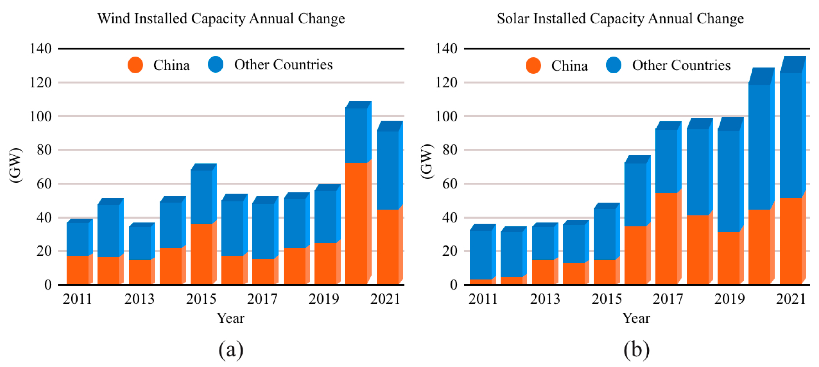
Figure 3.
Structural diagram of an FESS.
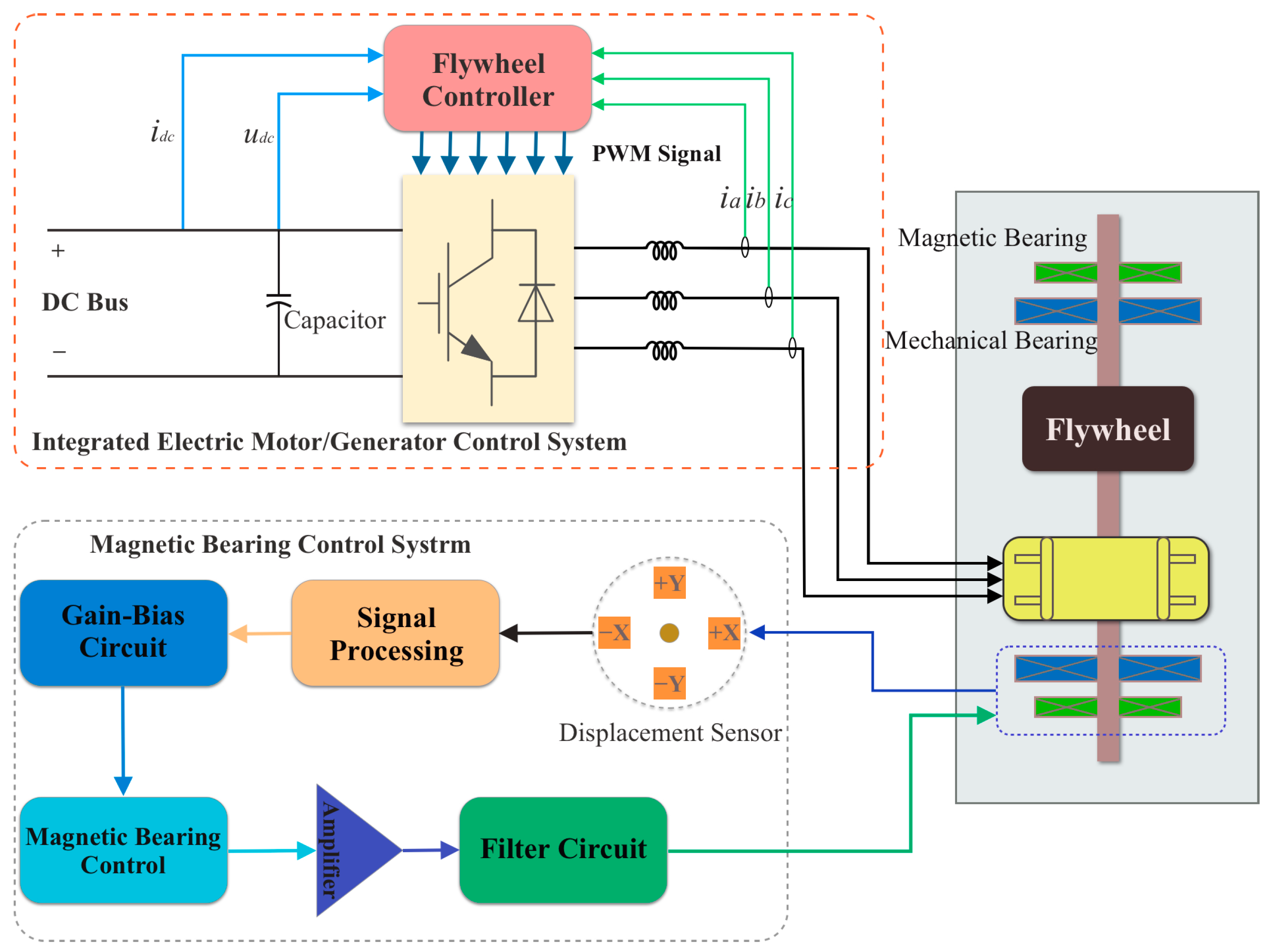
Figure 4.
Flywheel rotor shapes and shape coefficients [26].
Figure 4.
Flywheel rotor shapes and shape coefficients [26].

Figure 5.
Structures of (a) a homopolar inductor machine [30] and (b) a dual-rotor induction motor [37].


Figure 7.
Structure of an axial flux PM motor (a) exploded view and (b) side view [54].
Figure 7.
Structure of an axial flux PM motor (a) exploded view and (b) side view [54].
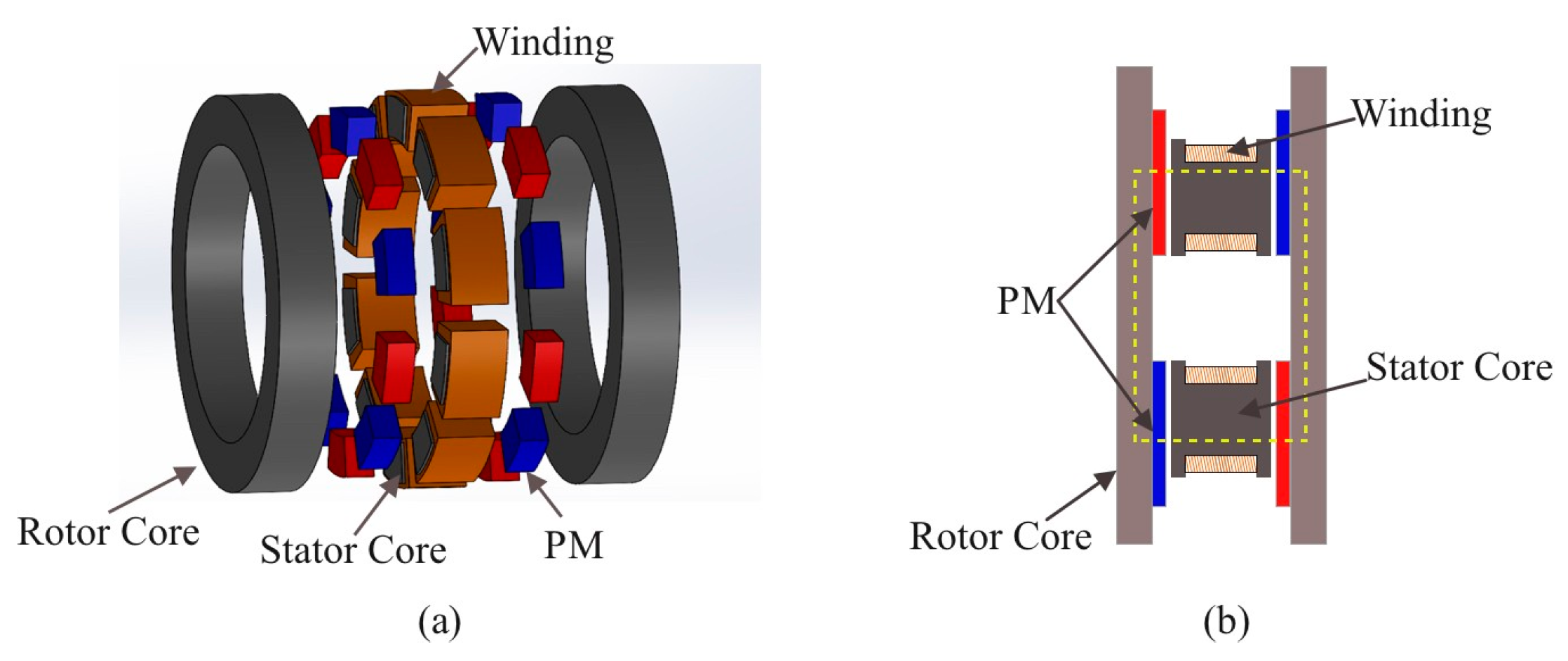


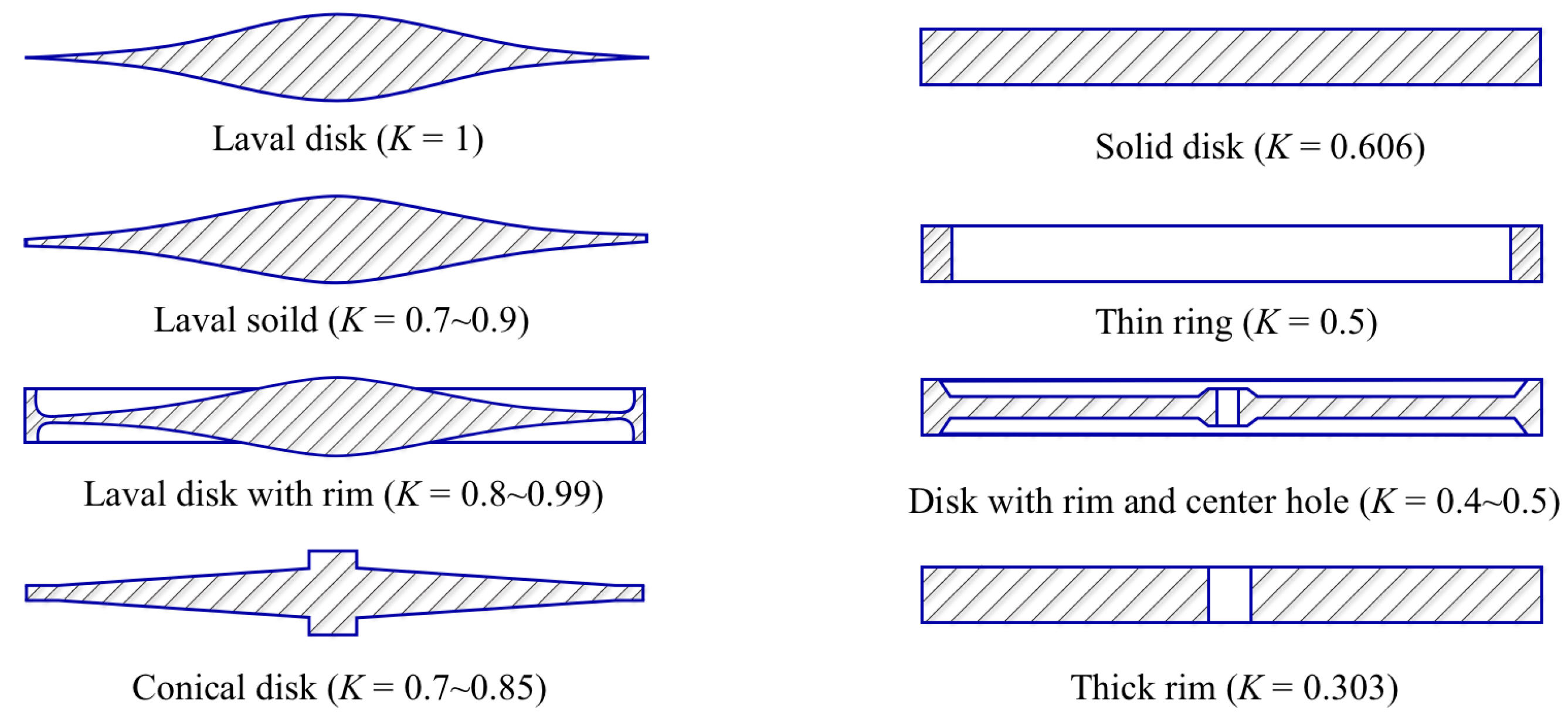
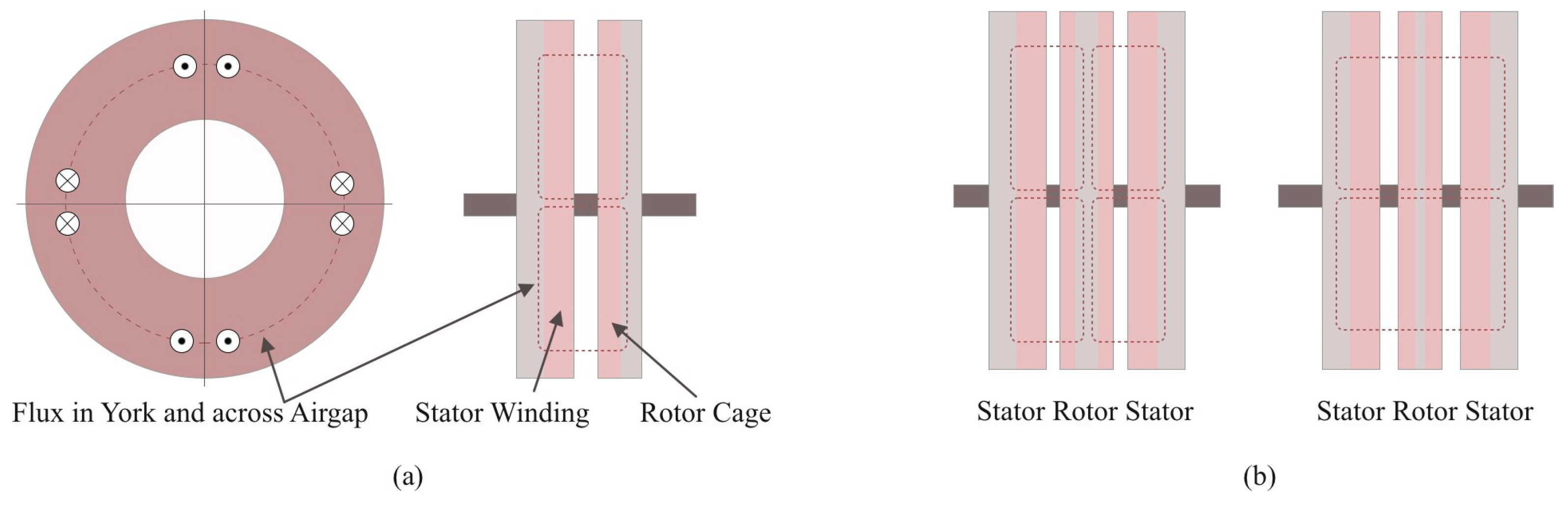
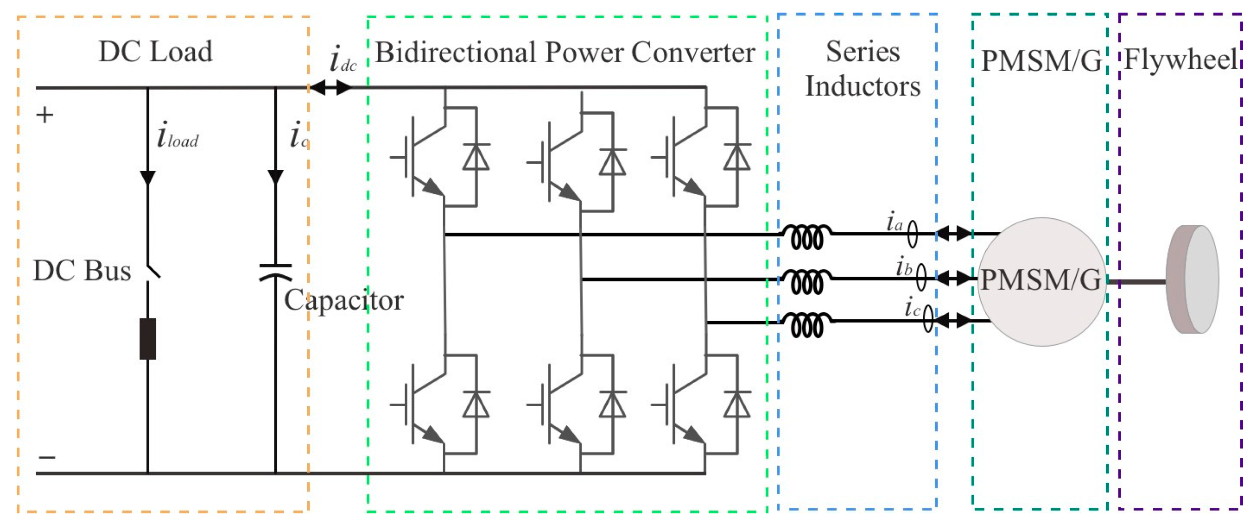
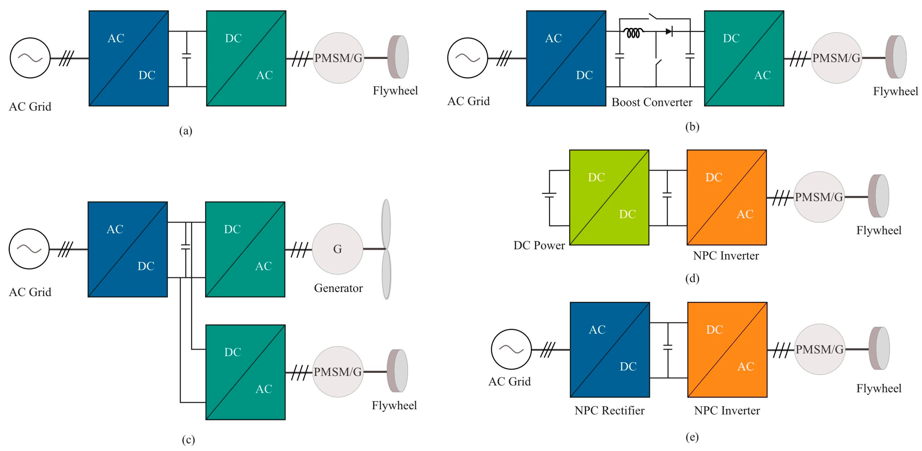
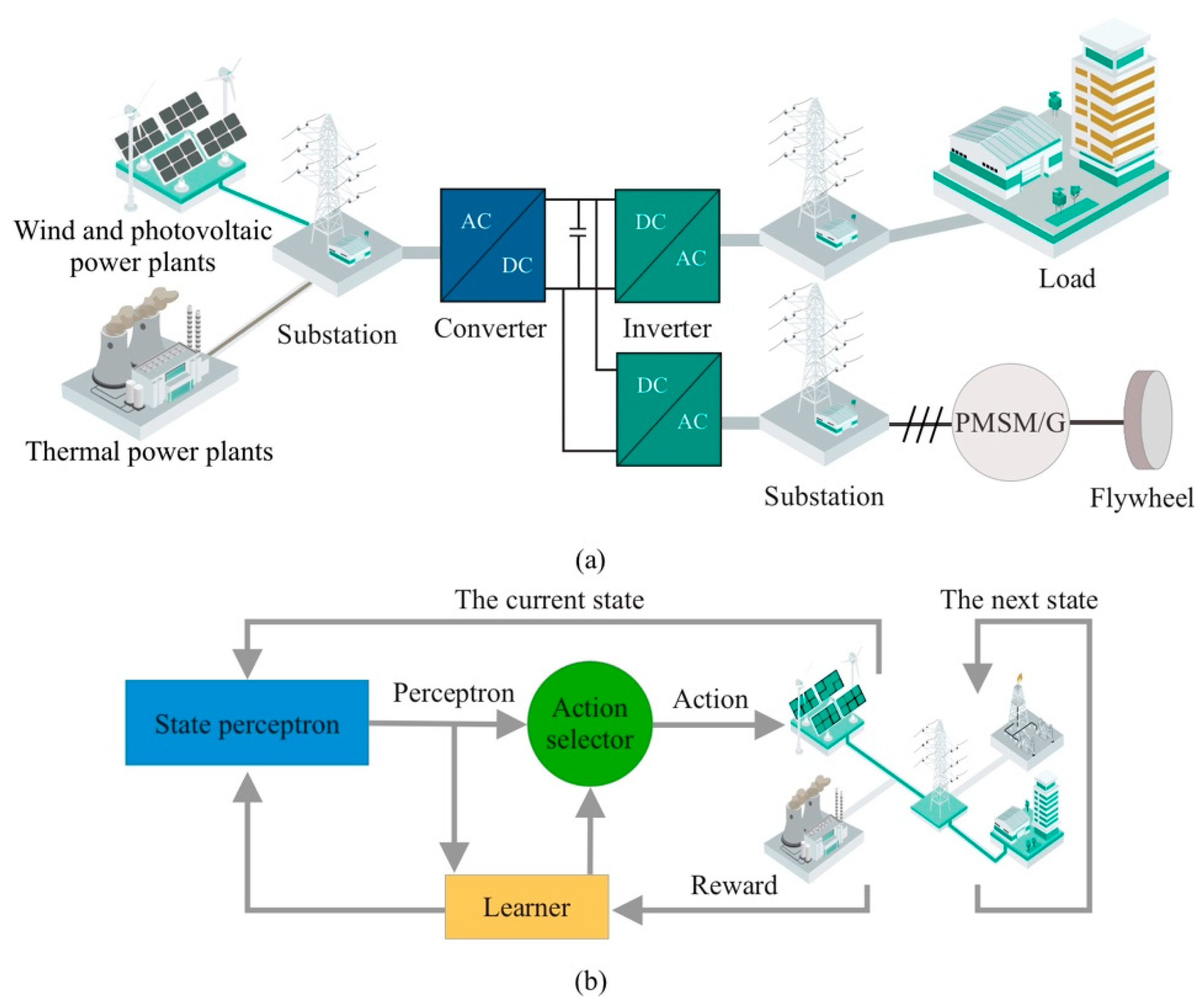
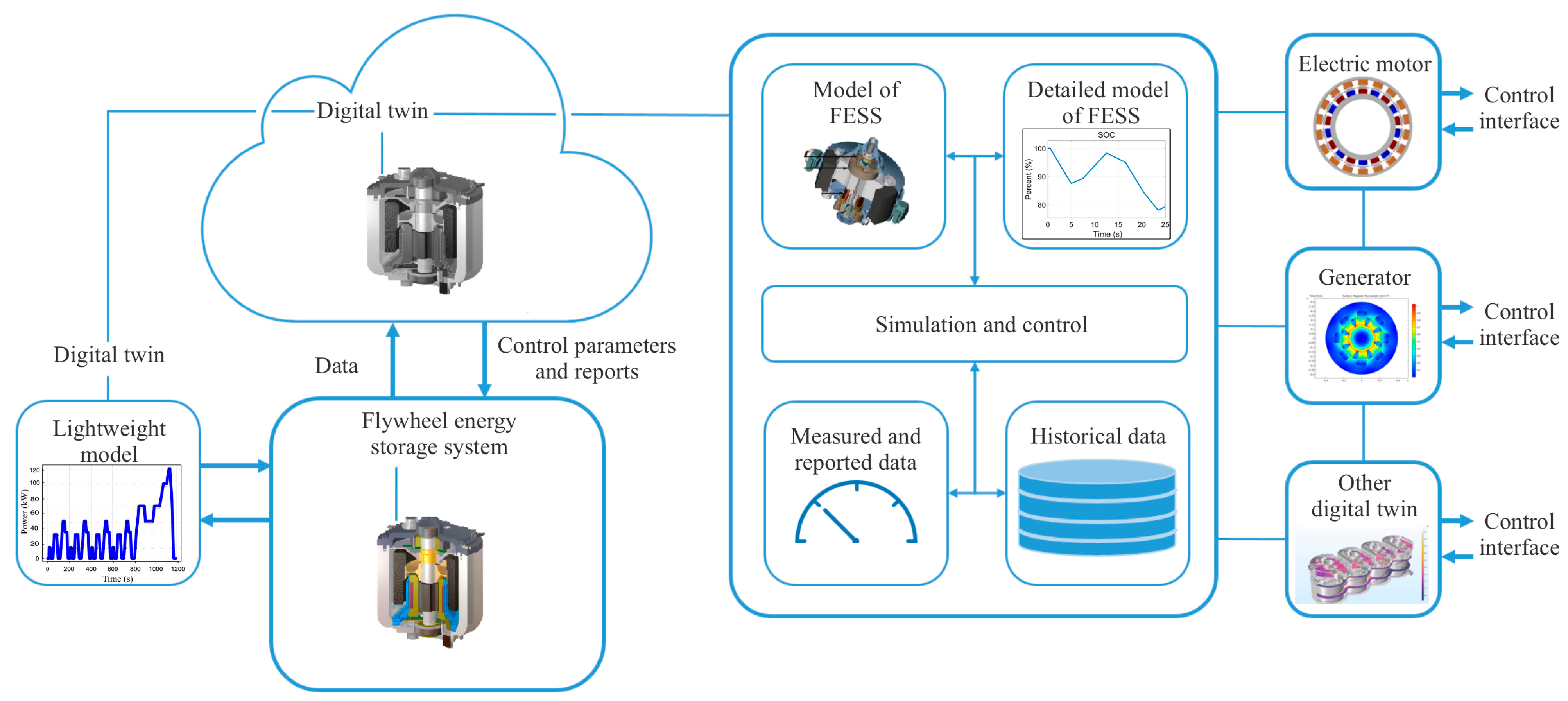
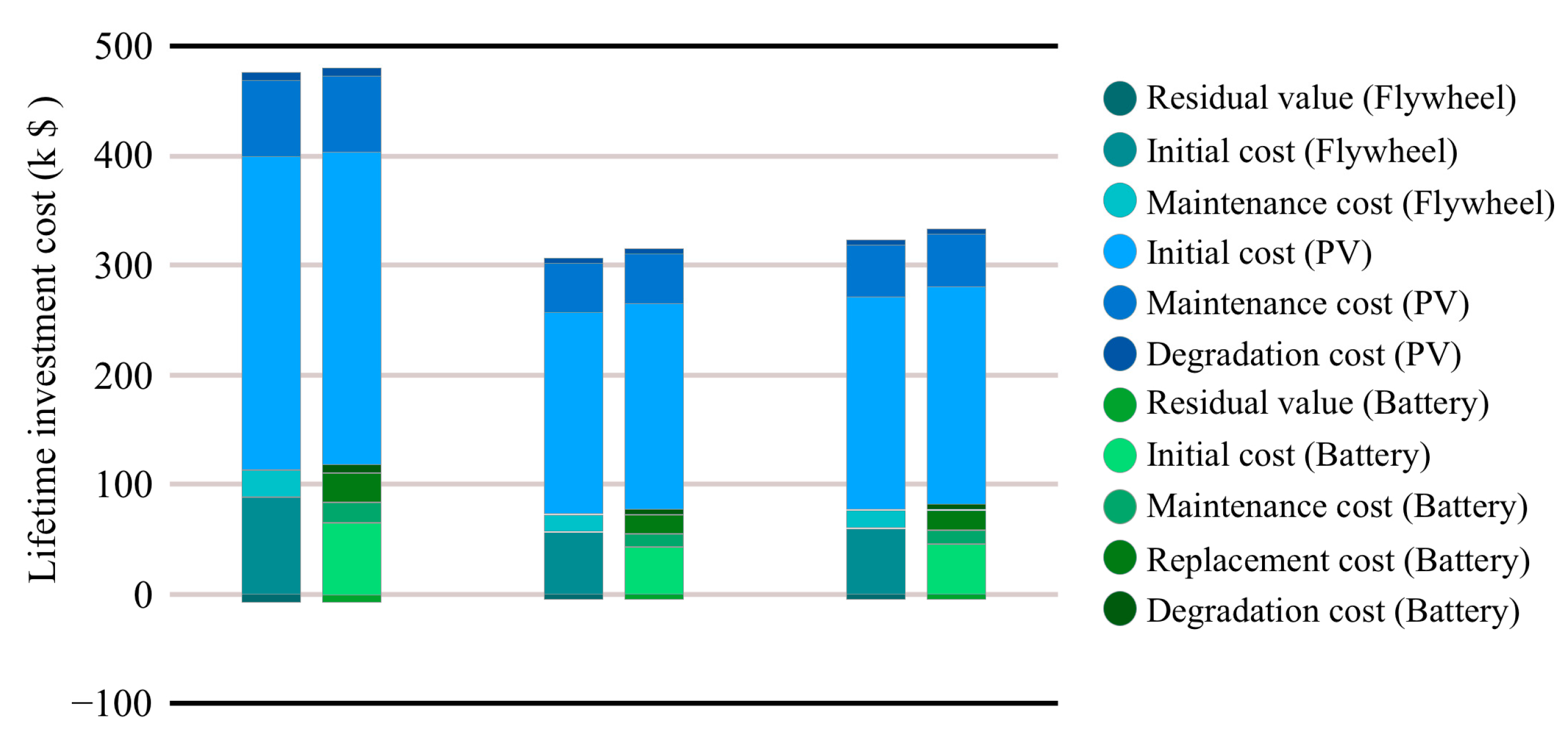
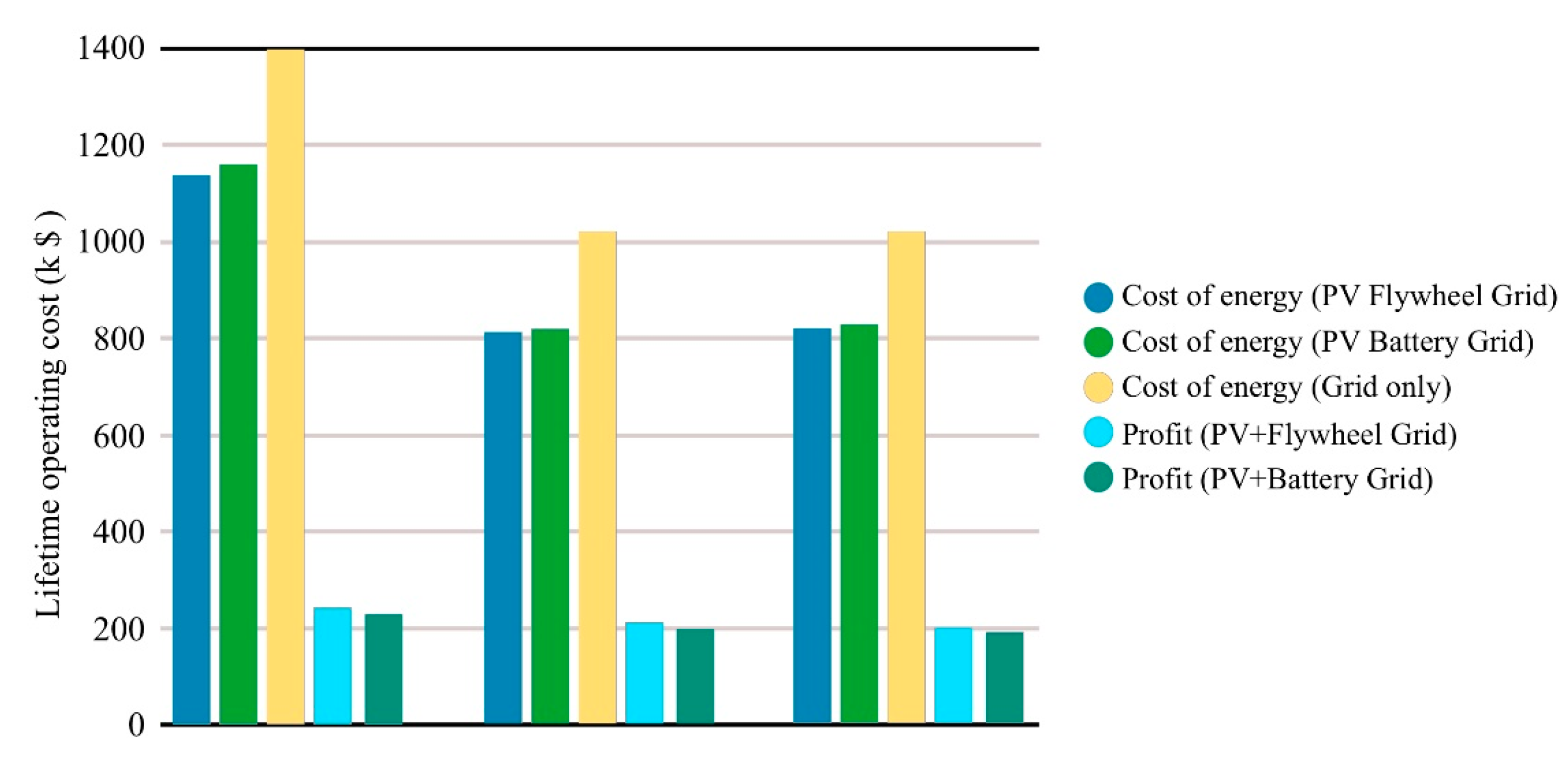
Figure 10.
Structures of bearings: (a) a permanent-magnet bearing [68], (b) an active magnetic bearing [69], (c) a superconducting magnetic bearing [70].
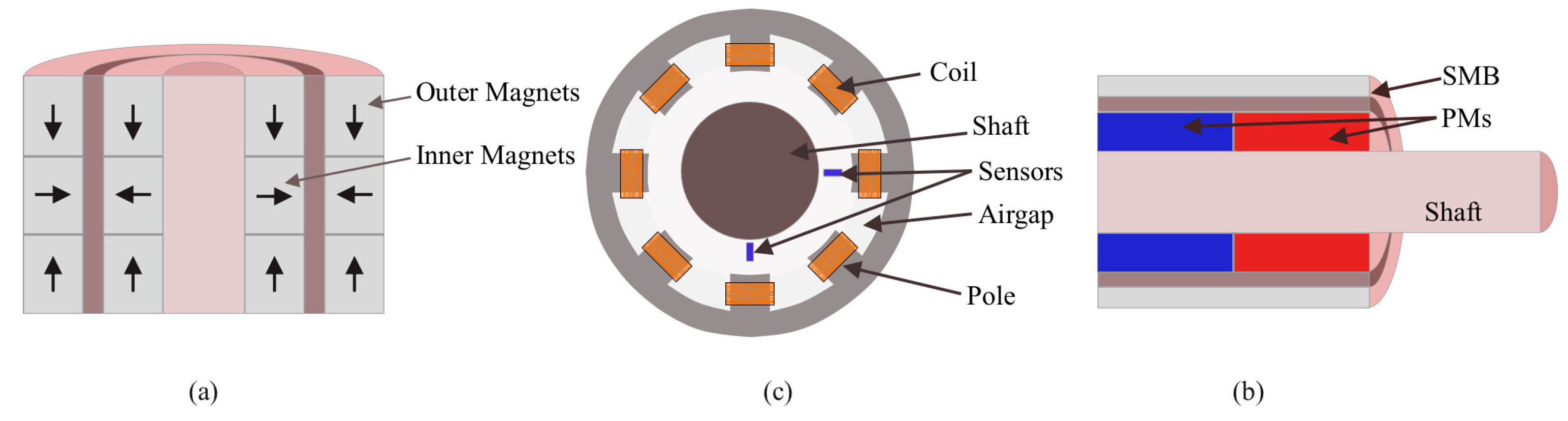
Figure 11.
Structure of a bidirectional converter system for a flywheel energy storage system [88].
Figure 11.
Structure of a bidirectional converter system for a flywheel energy storage system [88].

Figure 12.
Bidirectional converters: (a) BTB topology, (b) BTB configuration with a boost converter connected to the DC bus, (c) BTB with a wind generator, (d) DC-DC with NPC, (e) BTB NPC topology [94].
Figure 12.
Bidirectional converters: (a) BTB topology, (b) BTB configuration with a boost converter connected to the DC bus, (c) BTB with a wind generator, (d) DC-DC with NPC, (e) BTB NPC topology [94].

Figure 13.
ML model for safety risk analysis in a flywheel–battery hybrid ESS [156].
Figure 13.
ML model for safety risk analysis in a flywheel–battery hybrid ESS [156].

Figure 14.
Fault diagnosis process for flywheel bearings based on WMD energy entropy and deep learning [157].
Figure 14.
Fault diagnosis process for flywheel bearings based on WMD energy entropy and deep learning [157].
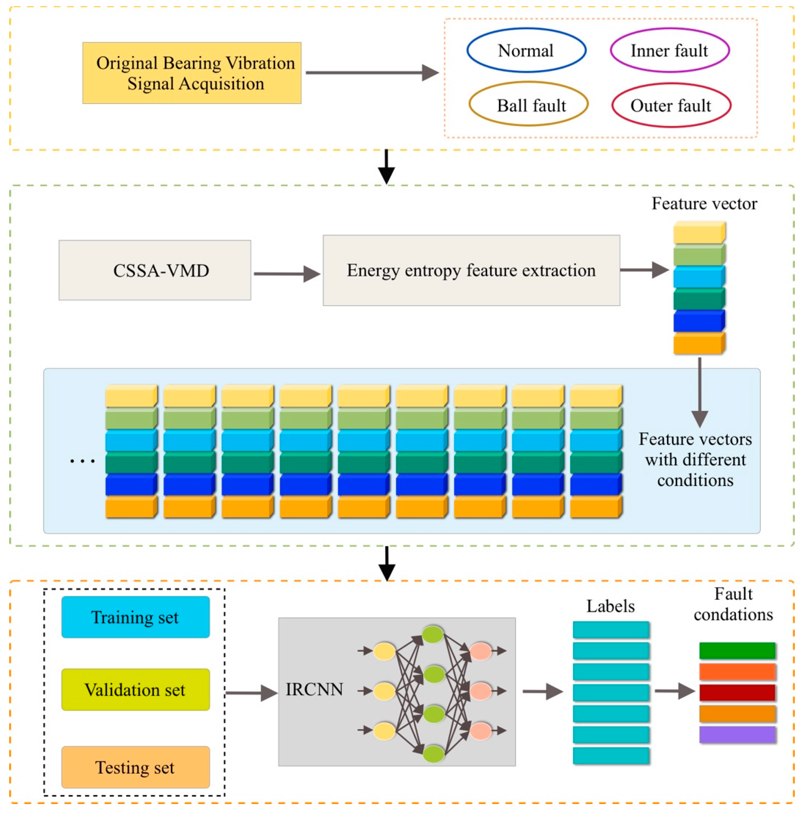
Figure 15.
(a) Power system with an FESS, (b) RL framework [155].
Figure 15.
(a) Power system with an FESS, (b) RL framework [155].

Figure 16.
Neural network control schematic of the PMSM [130].
Figure 16.
Neural network control schematic of the PMSM [130].
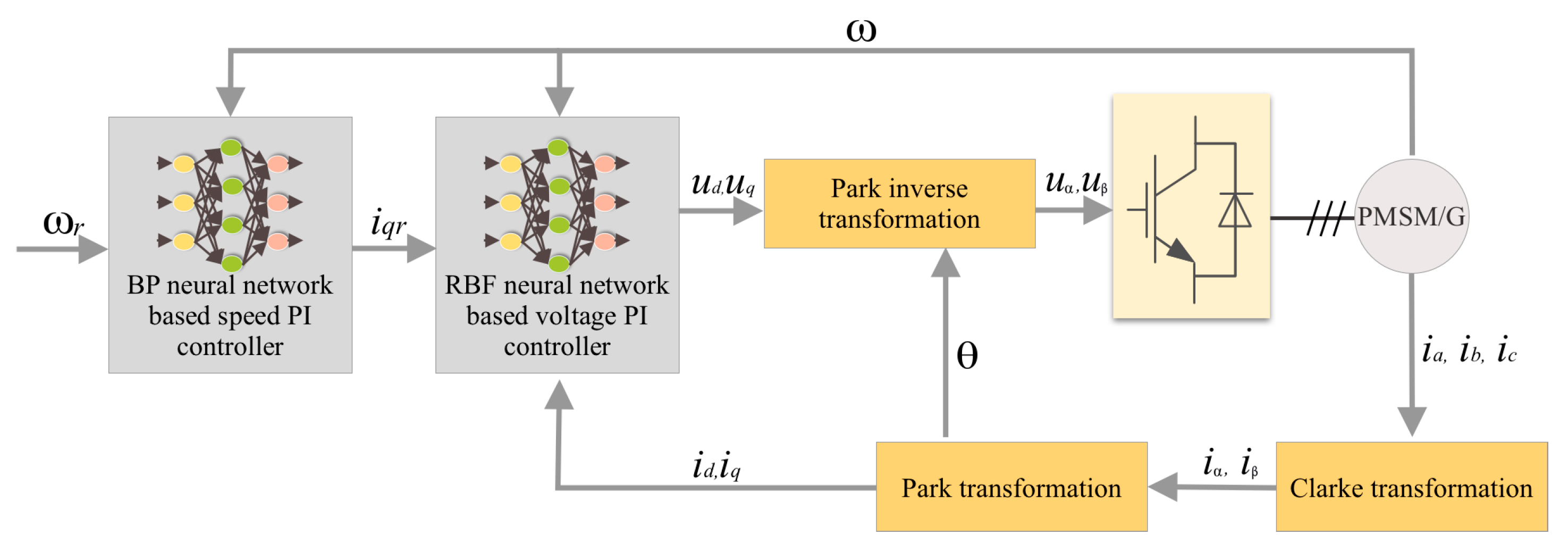
Figure 17.
Digital twin modeling scheme for an FESS.

Figure 18.
A data-driven FESS health management scheme.

Figure 19.
Schematic of a PV/flywheel-based EV charging system [160].
Figure 19.
Schematic of a PV/flywheel-based EV charging system [160].
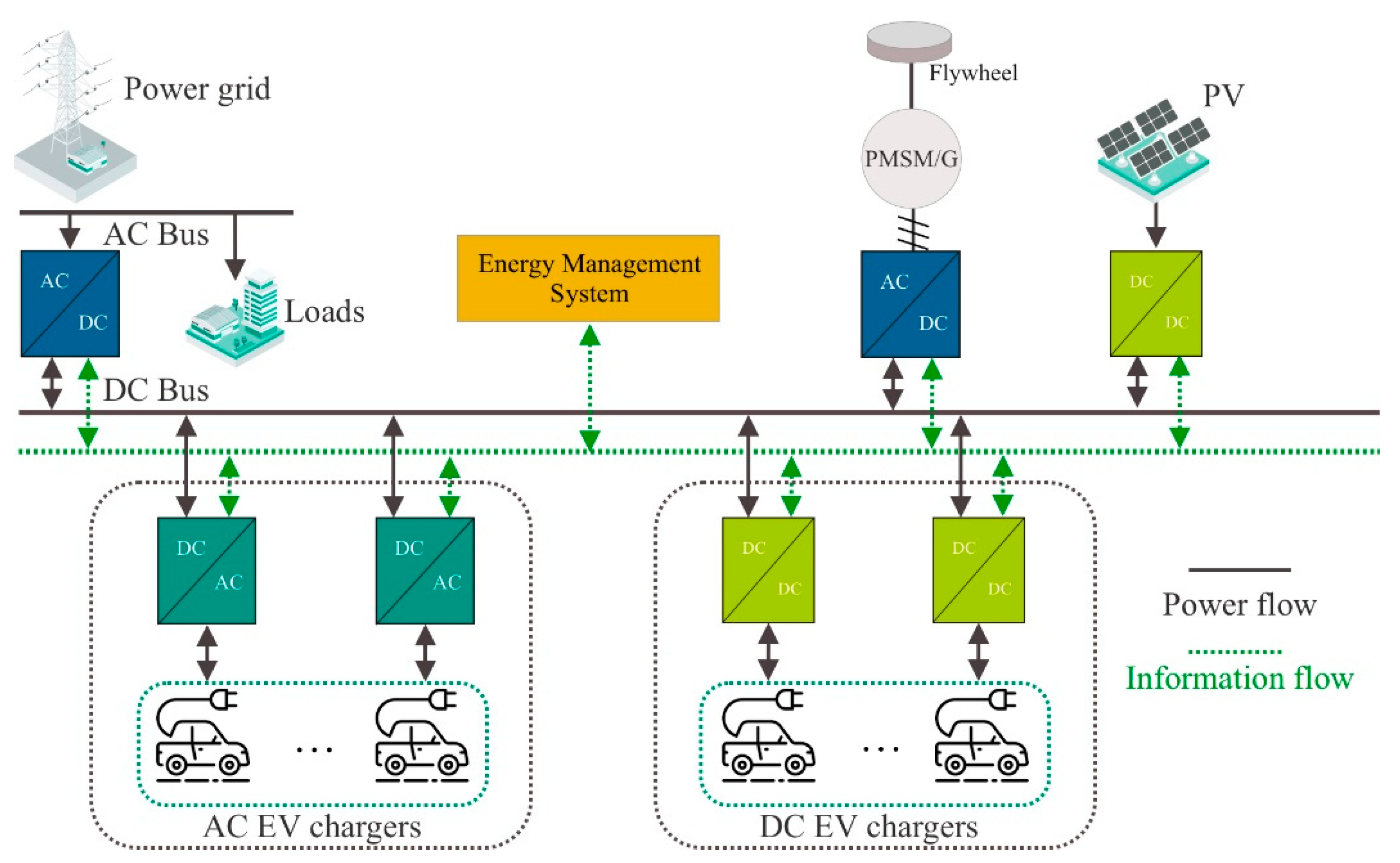
Figure 20.
The investment costs of the two hybrid systems, FL-PVHS and Bat-PVHS, in three locations.
Figure 20.
The investment costs of the two hybrid systems, FL-PVHS and Bat-PVHS, in three locations.

Figure 21.
Comparison of lifetime operation costs.

Figure 22.
Cumulative cash flows during system lifetime in (a) Brest, (b) Benguerir, and (c) Rabat.
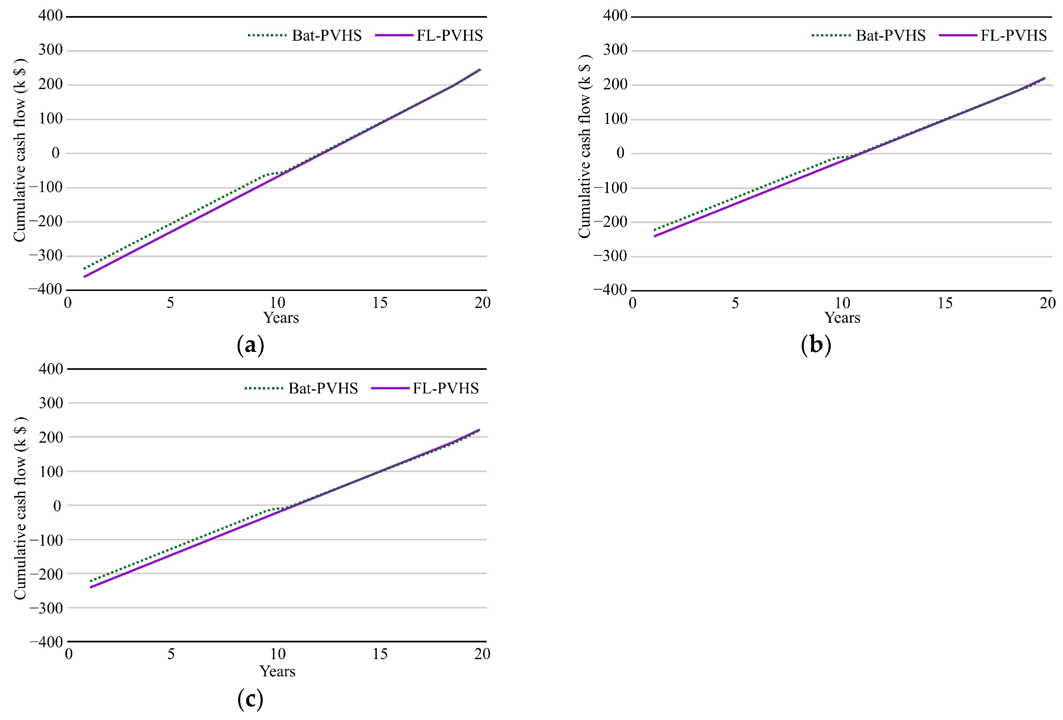
Table 2.
Maximum energy storage of flywheel rotor materials [25].
Table 2.
Maximum energy storage of flywheel rotor materials [25].
| Materials | Energy Storage of Different Materials | ||
|---|---|---|---|
| E glass fiber/resin | 3.5 | 2540 | 231.9 |
| S glass fiber/resin | 4.8 | 2530 | 320.6 |
| Kevlar | 3.8 | 1450 | 441.1 |
| Spectra fiber/resin | 3.0 | 970 | 520.6 |
| Carbon fiber T-1000/resin | 10 | 1800 | 945.7 |
| High-strength steel | 2.7 | 7800 | 56.8 |
| Aluminum alloy | 0.6 | 2700 | 36.1 |
Table 3.
Performance comparison of the three types of motors [25].
Table 3.
Performance comparison of the three types of motors [25].
| Features | Flywheel Motors | ||
|---|---|---|---|
| Induction Motor | Switched Reluctance Motor | Permanent Magnet Motor | |
| Output power | high | medium and low | medium and low |
| Specific power (kW/kg) | medium (~0.7) | medium (~0.7) | high (~1.2) |
| Rotor losses | copper and iron | iron loss | very low |
| Spinning losses | Removable by annulling flux | Removable by annulling flux | Non-removable, static flux |
| Efficiency (%) | High (91~94) | High (90) | Very High (95~97) |
| Control methods | Vector control | Synchronous: vector control. Switched: DSP | Sinusoidal: vector control. Trapezoidal: DSP |
| Size (l/kW) | 1.8 | 2.6 | 2.3 |
| Torque ripple | medium | high | medium |
| Maximum speed (rpm) | 900~15,000 | >15,000 | >30,000 |
| Demagnetization | no | no | yes |
| Cost | low | low | high |
l/kW—length (l) per unit power.
Table 4.
Characteristics of three single-magnet bearings.
| Bearing Type | Advantages and Disadvantages of Bearings | |
|---|---|---|
| Advantages | Disadvantages | |
| PMB | No power supply is required, a simple structure | Stable suspension cannot be achieved alone |
| AMB | Wear-free, low noise, no lubrication required, highly controllable | Amplifier losses are large, and the design and control are complex |
| SMB | Self-stabilizing | Requires a low-temperature chiller, large, and high-cost |
Table 5.
A summary of commercial FESS systems.
| Manufacturer | Rotor Material | Energy | Power | Duration | Application |
|---|---|---|---|---|---|
| Hitachi ABB [138] | - | - | 2 MW | - | Wind |
| Active Power [139] | Steel | 2.83 kW | 675 kW | 15 s | Various |
| Amber Kinetics [140] | Steel | 32 kW | 8 kW | 4 h | Various |
| Bacon Power [141] | Composite | 25 kWh | 100 kW | 15 min | Grid |
| Caterpillar [142] | - | 5 kWh | 675 kW | 15 s | UPS |
| Vycon [143] | Steel | 0.52 kWh | 125 kW | 15 s | UPS |
| Piller Group [144] | Steel | 2.9 kWh | 625 kW | 15 s | Various |
| Powerthru [145] | Composite | 0.53 kWh | 101 kW | 10–25 s | Defense |
| Rotonix [146] | Composite | 12 kWh | 1.1 MW | - | Various |
| Stornetic [147] | Composite | 3.6 kWh | 80 kW | 260 s | Grid |
s—seconds, min—minute, h—hours.
Table 6.
Applications and the advantages of using FESSs.
| Applications | Advantages of Using FESSs |
|---|---|
| UPS | FESSs can quickly supply stored energy to fill short-term gaps when the main power source fails, making them ideal for critical systems like hospitals, data centers, and industrial processes. |
| Frequency Regulation | FESSs can quickly absorb or discharge energy to help maintain a stable frequency, thus aiding in grid stability. |
| Renewable Energy Integration | FESSs can store excess energy generated by renewable sources. Their ability to charge and discharge quickly makes them well-suited for dealing with the intermittent nature of these energy sources. |
| Public Transportation Systems | In electric trains or trams, FESSs can capture the energy generated during braking and then reuse it for acceleration or other energy needs, thus improving the overall efficiency of the system. |
| Peak Shaving | FESSs can store energy during periods of low demand and release it during peak hours. This can be particularly beneficial for industries with fluctuating power requirements, reducing their peak demand charges. |
| Load Leveling in Microgrids | For small-scale localized grids, FESSs can serve to balance loads and supply, particularly when these microgrids are powered by renewable energy sources with fluctuating outputs. |
| High-Cycling Operations | FESSs are less susceptible to wear and tear from frequent cycling (charging and discharging) compared with other forms of energy storage like batteries, making them suitable for applications requiring frequent energy charge/discharge cycles. |
| High-Power, Short-Duration Applications | In industrial processes that require a high amount of power in a short period, like laser cutting or electric arc furnaces, FESSs can efficiently deliver the required energy burst. |
Table 7.
A summary of achievements of and challenges FESSs.
| Achievements | Challenges | ||
|---|---|---|---|
| Features | Details | Features | Details |
| High Energy Density | Modern FESS units can store a considerable amount of energy, comparable to chemical batteries, making them suitable for various applications ranging from grid support to transportation. | High Initial Costs | The upfront costs, particularly for advanced systems with magnetic bearings and vacuum enclosures, can be a deterrent to widespread adoption. |
| Fast Charge/Discharge Rates | Their rapid charge and discharge capabilities make FESSs ideal for applications requiring instant high power, like UPS systems and frequency regulation. | Complex Engineering | Maintaining a rotating mass at very high speeds requires precision engineering and advanced materials, adding to the complexity and cost. |
| Long Lifespan | Flywheels can endure a large number of cycles without significant wear, extending their operational life and reducing long-term costs. | Safety Concerns | Flywheels storing a large amount of energy can be potentially hazardous in case of failure, leading to strict safety requirements for their installation and operation. |
| Environmental Friendliness | Flywheels do not contain harmful chemicals and are generally easier to recycle, making them an environmentally responsible choice for energy storage. | Size and Weight | The energy-to-weight ratio for FESSs is still generally less favorable than for some other storage options, making them less practical for mobile applications. |
| Efficiency | Advances in materials science for the flywheels have led to higher rotational speeds and thus increased efficiency in energy storage and retrieval. | Limited Energy Storage Time | Flywheels are not ideal for long-term energy storage, limiting their application in scenarios requiring extended periods of storage. |
| Operational Reliability | The mechanical nature of FESSs, as opposed to the chemical processes in batteries, leads to fewer failure modes, contributing to operational reliability. | Regulatory Hurdles | As a relatively new technology in the public sphere, there may be regulatory challenges that need to be addressed, including standards for safety, integration into existing grids, and environmental assessments. |
Disclaimer/Publisher’s Note: The statements, opinions and data contained in all publications are solely those of the individual author(s) and contributor(s) and not of MDPI and/or the editor(s). MDPI and/or the editor(s) disclaim responsibility for any injury to people or property resulting from any ideas, methods, instructions or products referred to in the content. |
© 2023 by the authors. Licensee MDPI, Basel, Switzerland. This article is an open access article distributed under the terms and conditions of the Creative Commons Attribution (CC BY) license (https://creativecommons.org/licenses/by/4.0/).
Share and Cite
MDPI and ACS Style
Xu, K.; Guo, Y.; Lei, G.; Zhu, J. A Review of Flywheel Energy Storage System Technologies. Energies 2023, 16, 6462. https://doi.org/10.3390/en16186462
AMA Style
Xu K, Guo Y, Lei G, Zhu J. A Review of Flywheel Energy Storage System Technologies. Energies. 2023; 16(18):6462. https://doi.org/10.3390/en16186462
Chicago/Turabian StyleXu, Kai, Youguang Guo, Gang Lei, and Jianguo Zhu. 2023. "A Review of Flywheel Energy Storage System Technologies" Energies 16, no. 18: 6462. https://doi.org/10.3390/en16186462
Note that from the first issue of 2016, this journal uses article numbers instead of page numbers. See further details here.