
Analysis on Rotor Vibration Characteristics under Dynamic Rotor Interturn Short Circuit Fault in Synchronous Generators

1
Hebei Key Laboratory of Electric Power Machinery Maintenance and Failure Prevention, Department of Mechanical Engineering, North China Electric Power University, Baoding 071003, China
2
Department of Electrical and Electronics Engineering, University of Nottingham, Nottingham NG7 2RD, UK
*
Author to whom correspondence should be addressed.
Energies 2023, 16(18), 6585; https://doi.org/10.3390/en16186585
Submission received: 15 August 2023
/
Revised: 6 September 2023
/
Accepted: 11 September 2023
/
Published: 13 September 2023
Abstract
:A dynamic rotor interturn short circuit fault may occur during synchronous generator operation. However, there is no method to analyze the generator’s characteristics under the dynamic rotor interturn short circuit fault and identify the fault. In order to solve this problem, a new dynamic rotor interturn short circuit fault analysis model is creatively proposed through mathematical derivation. Firstly, the rotor vibration characteristics and the mechanical response under magnetic pull excitation are theoretically analyzed. In addition, a finite element modeling method for the dynamic rotor interturn short circuit fault is proposed, and an experimental device is designed. The model of a synchronous generator under the dynamic rotor interturn short circuit fault is established to obtain the rotor’s unbalanced magnetic pulls and mechanical responses by finite element calculation. Finally, the rotor vibrations are tested on a CS-5 prototype generator. The validity of the model is verified by finite element calculation and an experiment. This paper provides theoretical support for the diagnosis of a synchronous generator’s dynamic rotor interturn short circuit fault.
1. Introduction
As an energy-conversion device, the synchronous generator plays a vital role in the power system. The rotor of the synchronous generator is the core part of energy and power equipment [1]. The rotor vibration of the synchronous generator directly affects the operational reliability of the power system. Moreover, the vibration signal of the rotor can reflect the state of the generator [2]. The research on the rotor vibration is of great significance to the safe and efficient operation of synchronous generators. Therefore, the rotor vibration needs to be analyzed and monitored [3].
The generator rotor is in a high-speed rotating state for a long time. Hence, the rotor winding bears a strong centrifugal force [4]. And, coupled with generator manufacturing [5], maintenance, and other reasons, the RISC fault frequently occurs [6]. A short circuit is the result of failed insulation between rotor turns. In many cases, the rotor still runs under an interturn short circuit fault. The RISC, as a common electrical fault, leads to the significant vibration increase in the generator rotor [7]. In severe cases, the RISC fault causes the earth grounding of the rotor winding and the rotor core, which poses a serious threat to the safe and stable operation of the generator [8]. The condition of the rotor winding turn insulation is difficult to assess during a shutdown, which makes the fault not easy to detect [9]. Therefore, it is important to comprehensively analyze the RISC for the state perception and fault diagnosis of the synchronous generator.
So far, conventional monitoring and diagnostic methods have focused on measuring and analyzing changes in the electromechanical characteristics of the generator. For instance, Jiyong Hou et al. obtained an expression of the excitation MMF under the RISC and analyzed the effect of different short circuit locations on the excitation MMF [10]. Yucai Wu et al. analyzed the change in the generator operating point after a short circuit fault based on the expressions for electromagnetic power [11] and reactive power [12]. Yuling He et al. proposed a universal model of the RISC considering air-gap eccentricity and analyzed the phase current under the RISC [13]. In addition, the literature [14] provided an in-depth analysis of the shaft voltage caused by the RISC fault of the hidden pole synchronous generator. The literature [15] proposed an RISC fault diagnosis method based on the circulating current characteristics of the parallel branch circuit. Shuting Wan et al. found that the RISC fault causes the unbalanced electromagnetic force, which excites the rotor to vibrate at the fundamental frequency [16]. And the magnitude of the unbalanced electromagnetic force and the strength of the rotor vibration are related to the short circuit position, the number of short circuit turns, and the excitation current [17]. Guowei Zhou et al. analyzed the characteristics of the UMP on the rotor under the RISC fault [18]. Yang Li et al. found that generators with a different number of pole pairs and stator winding configurations have UMPs with different harmonic characteristics [19]. Guangtao Zhang et al. calculated the stator current and rotor current of a non-salient pole generator with a rotor interturn short circuit by applying the multi-loop method [20]. The literature [21] considered the effects of magnetic and thermal imbalance on rotor vibration in a comprehensive manner. Stefan Riegler et al. calculated the end winding electromagnetic forces under the RISC fault of the generator [22]. The literature [23] assessed the impact of a turn-to-turn short circuit in field windings on the steady-state variables of a turbo-generator. The limit of changes in the generator excitation current and reactive power under extreme conditions is obtained. The literature [24] found that the electromagnetic torque only has a DC component under the RISC fault, in which the DC component amplitudes decrease as the short circuit degree develops. Liangliang Hao et al. analyzed the electromagnetic torque before and after the RISC fault [25].
The above research results laid a solid foundation for monitoring and diagnosing the RISC fault. However, most of the literature studied the stable RISC fault, i.e., the SRISC fault. The SRISC fault is characterized by a constant short circuit state and is the late stage of the RISC fault [26]. In fact, the DRISC fault occurs due to the centrifugal forces of the winding [27] and the intensity of the generator vibration [28] in the actual operation. Different from the SRISC fault, the DRISC fault has a periodic feature and is in the early stage of the RISC fault. Konstantinos N. Gyftakis et al. studied the incipient interturn fault of the induction motors [29]. The eddy current in the shorted turns leads to the heat generation that causes the local hotspot. Further, the excessive heat leads to the faster degradation of the neighboring insulation [30]. The DRISC fault can be found early by monitoring the rotor vibration online during the operation of the generator. The further deterioration of the fault is prevented by timely maintenance [31]. It is important for the safe operation of synchronous generators.
Therefore, in order to make up for the lack of short-circuit-type research, this paper proposes the DRISC model in the synchronous generator. Compared with the rotor vibration under the SRISC, the rotor vibration is comprehensively calculated based on the DRISC model. The key contributions made in this study can be summarized as follows:
- (1)
- The refined model of the DRISC fault is established by mathematical derivation based on the fault characteristics.
- (2)
- The rotor vibration characteristics are comprehensively analyzed in detail based on the DRISC model by the time–frequency analysis method. In addition, the mechanical responses of the rotor are obtained under the DRSIC fault.
- (3)
- A specific test method is designed and implemented to simulate the DRISC fault.
The rest of the paper is organized as follows. In Section 2, the theoretical model of the RISC fault, including the DRISC fault and the SRISC fault, is given in detail. And the FEA calculation and the experimental tests are carried out in Section 3. Finally, the primary conclusions of the paper are drawn up and presented in Section 4.
2. Theoretical Analysis
The insulation protection capacity of the rotor winding generally reduces due to aging and damage to the insulation. Meanwhile, the weak insulating point between the winding turns may periodically reach the breakdown condition due to the vibration. For instance, the weak insulating point is directly opposite to and at the breakdown distance. The RISC fault takes place when the rotor winding insulation is broken.
Further, Figure 1 shows the schematic diagram of how the DRISC occurs. There are weak points in the winding insulation due to aging, wear, and other reasons. At time t1, there is still a certain distance h between the winding turns, which does not reach the breakdown condition. Hence, the rotor winding can still maintain normal working condition, as shown in Figure 1a. However, when the winding produces periodic flexural deformation due to the vibration, as shown in Figure 1b, the upward flexural deformation of the upper winding is suppressed due to the rotor slot and the tightness of the winding, while the flexural deformation of the lower winding reduces the gap length between winding turns to the minimum distance h1. When h1 is small enough, the voltage of the winding breaks through the insulating weak points, resulting in the DRISC fault. Hence, the DRISC fault is obviously periodic.
2.1. Impact of DRISC on MFD
When the generator is in normal operation, the air-gap magnetic field is symmetrically distributed. The MFD can be obtained by multiplying the PPUA by the MMF. The permeance per unit area is determined by the air-gap length, as illustrated in Equation (1).
In Equation (1), μ0 is the vacuum permeability, g0 is the radial air-gap length of the generator, and αm is the circumferential angle of the air-gap. Hence, Λ0 is the PPUA, which is a constant.
The physical model of the RISC fault is shown in Figure 2. Observing the rotor circuit, the effective ampere-turn numbers of the rotor winding significantly reduce under the RISC fault. As the reactance of the short circuit path is much smaller than that of the original path, the excitation current no longer passes through the original path, rather through the short circuit path, as shown in Figure 2.
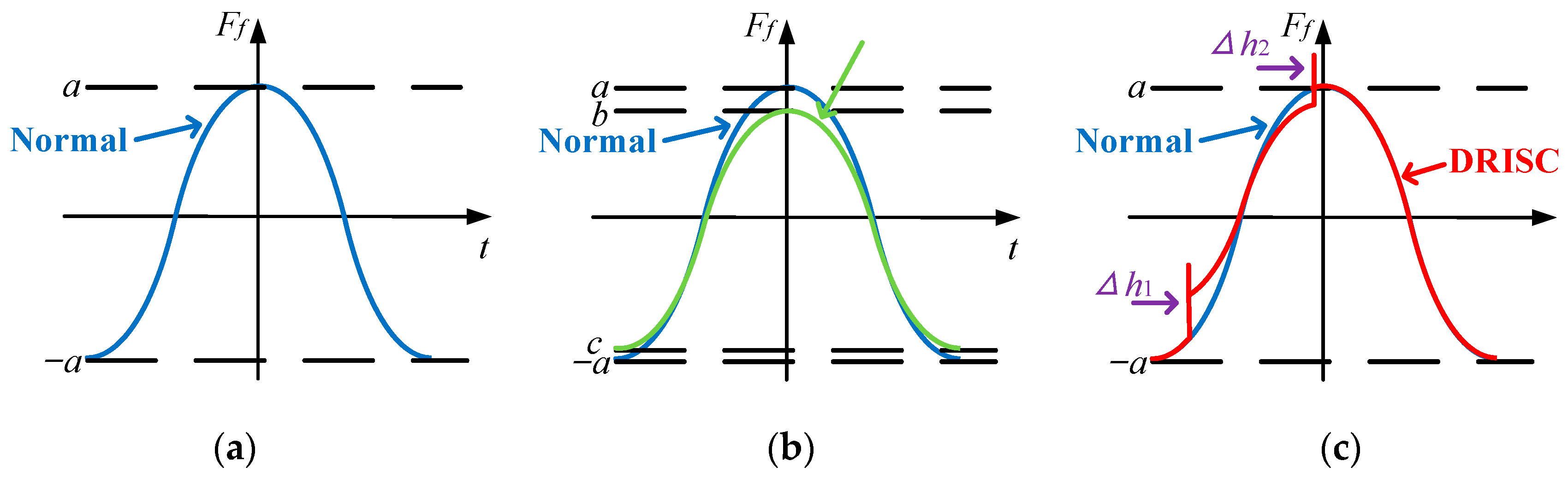
The RISC fault mainly affects the air-gap MMF of the generator. Further, the air-gap MFD changes. An additional reverse MMF is superimposed on top of the original air-gap MMF under the RISC fault. The air-gap MMFs in different cases are shown in Figure 3a–c.
The air-gap MMF under the RISC fault is equivalent to the reverse MMF generated by the reverse current superimposed on the air-gap MMF under the normal condition. In the case of the DRISC, the reverse current is applied to the rotor circuit in the form of a pulse signal. In the case of the SRISC, the reverse current is applied to the rotor circuit in the form of a step signal.
The additional MMF resulting from the RISC can be expressed as Equation (2).
In Equation (2), Fd is the reverse MMF, nm is the number of short circuit turns, β′ is the initial position angle of the slot where the interturn short circuit occurs, αr is the angle between the two slots where the short circuit turns are in, and If is the excitation current.
The reversed MMF Fd(θr) can be expanded by a Fourier series as
The additional MMF generated by the short circuit can be expressed as
The first harmonic vectors of the air-gap MMF before and after the RISC are shown in Figure 4. The black arrows represent the physical quantities under normal conditions. The blue arrows represent the physical quantities of the generator under rotor short circuit fault. Fr is the fundamental main MMF generated by the rotor winding; Fs is the main MMF of the armature reaction; Fc is the fundamental synthetic MMF of the generator; ψ is the internal work angle, the value of which is determined by the nature of the load; I is the armature current; and E0 is the excitation MMF.
According to the vector relationship in Figure 4, the air-gap MMF f (αm, t) under different operating conditions can be written as Equation (6).
Combining Figure 4 and Equation (6), it can be seen that the air-gap MMF decreases as the DRISC takes place. There are only odd harmonic components in the air-gap MMF under normal conditions. Even harmonics appear in the air-gap MMF under the DRISC fault. Compared with the MMF under the SRISC, the MMF under the DRISC contains pulsed signals.
The MFD B (αm, t) can be obtained by multiplying the permeance per unit area (PPUA) Λ0 with the MMF f (αm, t). Further, the air-gap MFD B (αm, t) before and after the DRISC can be obtained by Equation (7).
As can be seen from Equation (7), the air-gap MFD decreases as the DRISC fault takes place. There are only odd harmonics in the MFD under normal conditions. However, even harmonics appear in the MFD under the DRISC fault. The amplitude of the odd harmonics decreases while the amplitude of the even harmonics increases, as the short circuit degree intensifies. Overall, the MFD amplitude under the DRISC is somewhere between the normal conditions and the SRISC fault of the same short circuit degree.
2.2. Impact of DRISC on UMP
The generator rotor is a solid cylindrical structure with a large stiffness. It is subjected to the magnetic pull at all points on its outer surface. The substantial excitation force of the rotor vibration is the combined force obtained by integrating the magnetic pull per unit area on the outer surface of the rotor over the entire circumference.
The magnetic pull per unit area on the generator rotor based on the Maxwell stress method under RISC is
As can be seen from Equation (8), the magnetic pull per unit area of the rotor is proportional to the square of the MFD and should have the same trend as the MFD.
Integrate by Maxwell’s method according to the following equation.
The components of the rotor UMP in the x and y directions under normal conditions can be obtained as
As can be seen from Equation (10), under normal conditions, the rotor UMP in the x-direction and y-direction is zero, so, theoretically, the rotor does not produce any radial vibration.
The components of the rotor UMP in the x and y directions under the SRISC are
Based on Equation (11), the SRISC fault produces a fundamental frequency radial vibration on the rotor. And, as the short circuit degree increases, the rotor UMP increases. Further, the rotor vibration becomes more violent.
The components of the rotor UMP in the x and y directions under the DRISC are shown in Equation (12).
Observing Equation (12), the rotor UMP in both the x and y directions contains the fundamental frequency, which excites the radial rotor vibration in the fundamental frequency under the DRISC fault. And, as the short circuit degree increases, both the UMP and the vibration increase. In general, the rotor UMP under the DRISC is less than that under the SRISC when the short circuit degree is same. In a dynamic interturn short circuit cycle, when the normal state and the short circuit state are transformed into each other, a pulse signal is generated in the rotor UMP. The UMP rapidly increases as the normal state is transformed into the fault state. Oppositely, the UMP sharply decreases as the fault state is transformed into the normal state. The rotor UMP under the DRISC is somewhere between the normal state and the SRISC state.
The two ends of the rotor are fixed by end covers or bearing pedestals. The equivalent mechanical model of the rotor can be simplified as a fixed beam structure at both ends, rotating about the z-axis. As shown in Figure 5, the rotor model can be equated to a mass–spring–damping system, where Fx and Fy are the external exciting forces of the x and y axes, xx(t) and xy(t) are the vibration displacements of the rotor core in the x and y axes, kx and ky are the stiffness coefficients in the x and y axes, and Dx and Dy are the damping coefficients in the x and y axes. The dynamics equation of the generator rotor system can be expressed as Equation (13).
where [m] is the mass matrix of rotor, [D] is the radial damping matrix, [K] is the radial stiffness matrix, y(t) is the displacement of the unit particle, y′(t) is the velocity, y″(t) is the acceleration (a), and f(t) is the exciting force of the rotor system, i.e., the UMP of the rotor.
From the perspective of the magnetic pull excitation and the primary forced vibration response, the UMP is the excitation of the rotor core, and the displacement is the vibration amplitude. Since the UMP is periodic, its corresponding displacement response is also periodic. This periodic displacement is vibration. As can be seen from Equation (13), the greater the UMP on the rotor is, the greater the amplitude of the vibration is. In engineering practice, vibration testing is usually carried out using acceleration sensors, with measurements that reflect the second derivative of the displacement.
3. FEA and Experimental Validation
3.1. FEA and Experimental Setup
To verify the conclusion above, a CS-5 hidden pole fault simulation generator is taken as an example. The finite element model of the DRISC fault is established and calculated with the SRISC fault as the control group. Meanwhile, the experiments are carried out under normal conditions: the DRISC fault and the SRISC fault. The specific parameters of the CS-5 generator are shown in Table 1.
The CS-5 hidden pole fault simulation generator is a one-pair pole synchronous generator, which is connected to the drive motor by means of a coupling. And the speed of the drive motor is adjustable by a frequency converter. The generator out-put voltage adopts the three-phase four-wire output mode, and each phase voltage is 220 V/50 Hz. The appearance of the test bench is shown in Figure 6.
The rotor UMP is difficult to directly measure in the generator, while the rotor vibration response under the UMP is easily obtained in the experiments. According to the same frequency correspondence between the excitation and response, the frequency components and amplitude changes in the rotor vibration are the external reflection of the frequency components and amplitude changes in the excitation source.
The RISC fault setting is shown in Figure 7. The generator is additionally equipped with a rotor winding interturn short circuit tap terminal block on the outside of the generator, which can be connected to different short circuit taps to set different degrees of the RISC fault, including 0% (L1), 5% (L2), 10% (L3), 15% (L4), and 100% (L5). The experiments in this paper are set up with 0% (L1), 5% (L1–L2), and 10% (L1–L3) for three different degrees of the interturn short circuit. The experiments are carried out in a total of five groups: Group 1: normal operation without RISC; Group 2: 5% SRISC; Group 3: 10% SRISC; Group 4: 5% DRISC; Group 5: 10% DRISC. The SRISC can be simulated by directly shorting the corresponding taps. The DRISC is controlled by a DC solid state relay and a PWM square wave generator with an adjustable duty ratio. The DRISC trigger circuit is shown in Figure 7c. The optocoupler in the DC solid state relay is triggered by the square wave signal to realize the periodic DRISC fault without any contact.
In the finite element simulation, the section of the short circuit winding bar is divided into two components. One is to simulate the short circuit part and the other is to simulate the healthy part, as shown in Figure 7a. In addition, the dynamic interturn short circuit is shorted by means of an external coupling circuit voltage control switch S_A1.
The schematic diagram of the pulsed voltage source is shown in Figure 7b, where Td is the delay time, Tr is the rise time, Tf is the fall time, Pw is the pulse width, and Period is the pulse period. Von is the trigger voltage of the voltage-controlled switch. When the value of the pulse voltage source is greater than Von, the switch S_A1 operates, i.e., the short circuit occurs in the excitation circuit. Voff represents the cut-off voltage of the voltage-controlled switch. When the value of the pulse voltage source is less than Voff, the switch S_A1 breaks, i.e., the excitation circuit returns to the normal condition. The duty cycle of the short circuit and the frequency of the dynamic short circuit are varied by adjusting the Pw and Period. By setting the above parameters, the dynamic interturn short circuit with a period of 20 ms and a duty cycle of 25% is generated. And the duty cycle of the static interturn short circuit is 100%.
3.2. Results and Discussion
The changes in the air-gap MFD obtained by the finite element simulation before and after the short circuit are shown in Figure 8. As can be seen from Figure 8a, the MFD decreases as the DRISC fault occurs. And the reduction in the MFD under the DRISC fault is less than that of the SRISC fault with the same short circuit degree. The greater the short circuit degree is, the smaller the amplitude of the MFD is.
It is shown in Figure 8b–f that there are only odd harmonics in the MFD under normal conditions. The DRISC fault causes even harmonics to appear in the air-gap MFD. As the short circuit intensifies, the amplitude of the odd harmonics decreases while the amplitude of the even harmonics increases. The amplitude of each harmonic of the air-gap MFD under the DRISC fault is between the normal condition and the SRISC fault of the same short circuit degree. Equation (7) in the theoretical analysis section shows that even harmonics appear in the air-gap MFD under the DRISC fault. With the increase in the short circuit degree, the odd harmonic amplitude decreases, and the even harmonic amplitude increases. The finite element simulation results of the air-gap MFD in Figure 8 are in agreement with the expression of the air-gap MFD in Equation (7) in the theoretical analysis.
In addition, the air-gap MFD results show that the DRISC fault is the RISC fault in the development phase, due to a small amount of variation in the characteristic parameters. Comparing with the SRISC fault, the DRISC fault has less impact on generator performance.
Figure 9 shows the finite element simulation results of the rotor UMP. From Figure 9a, we can see that the rotor UMP rapidly increases in the form of a “spike” under the DRISC, which is equivalent to a pulse signal superimposed on the original UMP. And the “spike” is generated on the rotor UMP at the end of the DRISC. As the dynamic short circuit increases, the amplitude of the pulse signal increases, which is reflected on the graph as a higher “spike”. In each dynamic interturn short circuit cycle, the rotor UMP is basically zero before the short circuit starts. The UMP under the DRISC fault is less than the UMP under the SRISC fault with the same short circuit degree. With the increase in the dynamic short circuit degree, the rotor UMP increases. Equation (12) in the theoretical analysis section shows that the rotor UMP contains the fundamental frequency under the DRISC fault. As the short circuit degree increases, the UMP increases. And the rotor UMP under the DRISC is less than that under the SRISC when the short circuit degree is the same. The finite element simulation results of the rotor UMP in Figure 9 are consistent with the expression of the rotor UMP in Equation (12) in the theoretical analysis.
Figure 9b shows the spectrum of the rotor UMP under different types and degrees of interturn short circuits. From Figure 9b, we can see that the UMP of the rotor under normal conditions contains only the fundamental frequency, and its amplitude is almost zero, which is basically consistent with the theoretical analysis of Equation (10). The fundamental frequency amplitude of the UMP increases under the SRISC fault. And the greater the short circuit degree is, the higher the fundamental frequency amplitude is. The expression of the rotor UMP under the SRISC fault in Equation (11) shows that with the increase in the short circuit degree, the fundamental frequency amplitude of the rotor UMP increases. The finite element simulation results of the rotor UMP under the SRISC fault are in agreement with Equation (11). The fundamental frequency amplitude of the UMP increases under the DRISC fault while the amplitude is smaller than that of the SRISC fault with the same short circuit degree, which is in accordance with Equation (12).
Figure 10 shows the vibration responses obtained by experiments under different operating conditions. In Figure 10f, the fundamental frequency of the rotor vibration response should theoretically be zero. But the actual results show that there is the fundamental frequency vibration under normal conditions due to instrument testing errors. It is obvious from Figure 10 and Figure 11 that the fundamental frequency of the rotor vibration response under the DRISC fault significantly increases. The fundamental frequency of the rotor UMP significantly increases as the DRISC fault occurs. Hence, the corresponding amplitude of the fundamental frequency vibration clearly increases.
And, as the degree of the short circuit increases, the rotor fundamental frequency vibration is more violent. In overall terms, the amplitude of the rotor’s fundamental frequency vibration under the DRISC fault is less than the amplitude of the rotor’s fundamental frequency vibration under the SRISC fault of the same short circuit degree. The expression of Equation (12) for the rotor UMP and the finite element results of the rotor UMP in Figure 9 both show that the rotor UMP contains the fundamental frequency, and the larger the short circuit degree is, the larger the fundamental frequency amplitude is. The experimental results of the rotor vibration response in Figure 10 coincide with the theoretical expression of the rotor UMP in Equation (12) and the finite element simulation results of the rotor UMP in Figure 9.
Figure 11 shows the RMS values, the first harmonic amplitude of the UMP obtained from the simulation, the first harmonic amplitude of the rotor vibration response obtained from the experiment, and their variation trends. The variation trends of the fault parameters are obtained by comparing them with the parameters under normal conditions.
In order to further analyze the deformation and mechanical response of the rotor core under the UMP, the magnet–solid coupling simulation is carried out in ANSYS Workbench 18.2 software. The corresponding coupling block diagram is shown in Figure 12. The deformation and mechanical response of the rotor can be obtained by importing the mechanical data of the rotor calculated in the electromagnetic module into the transient structural module. The results are shown in Figure 13, Figure 14 and Figure 15 and Table 2.
Figure 13 shows the deformation response of the rotor under different operating conditions. The unit of the data in the Figure 13 is m. The max deformation appears in the top of the tooth near the large tooth. As the degree of the short circuit increases, the max deformation increases. Moreover, the max deformation of the rotor under the DRISC is smaller than that of the SRISC at the same short degree.
Figure 14 and Figure 15 show the strain response and the stress response of the rotor under different operating conditions. The units of the data in Figure 14 and Figure 15 are m/m and Pa. The stress concentration is large in the area of the ends of the four small teeth close to the large teeth. The greater the degree of the short circuit is, the greater the strain and stress response of the rotor are. Furthermore, the strain and stress response amplitude of the rotor under the DRISC is less than those under the SRISC with the same short circuit degree.
4. Conclusions
In this paper, we study the rotor vibration characteristics based on a creative DRISC model in synchronous generators. Compared with the SRISC fault, the impact of the DRISC fault on the rotor UMP is obtained by theoretical analysis, finite element calculation, and an experiment. The primary conclusions are as follows.
- (1)
- Compared with the normal condition, the air-gap MFD decreases under the DRISC fault, and the DRISC generates additional even harmonics. As the short circuit intensifies, the amplitudes of the odd harmonics decrease while the amplitudes of the even harmonics increase in the MFD spectrum.
- (2)
- The rotor UMP rapidly increases and contains the first component as the DRISC takes place. And the UMP of the rotor increases with the increase in the short circuit degree. Correspondingly, the first harmonic amplitude of the rotor vibration response increases. In addition, the mechanical response of the rotor, which is caused by the UMP, is obtained when the dangerous position in the rotor winding is identified.
- (3)
- Compared with the SRISC, the UMP curve under the DRISC fault shows two distinct “spikes”, which are higher as the DRISC degree increases. The UMP of the rotor under the DRISC is equivalent to superimposing a pulse signal on top of the original rotor’s magnetic pull.
This work is an innovative supplement to the research on the RISC fault by the proposed DRISC model. In this work, the UMP expression of the rotor under the DRISC fault is derived. Further, the radial vibration characteristics of the rotor are obtained by FEA and experiments in order to verify the validity of the UMP expression. The correlation between the RISC and the rotor vibration is thoroughly revealed. The results of this paper are an additional supplement to the existing research on the RISC fault in synchronous generator. This study is important for the detection and diagnosis of the rotor vibration of synchronous generators.
Author Contributions
Conceptualization, Y.H.; writing—original draft preparation, M.J.; writing—review and editing, K.S., M.Q. and D.G. All authors have read and agreed to the published version of the manuscript.
Funding
This research was funded by the National Natural Science Foundation of China (52177042), the National Natural Science Foundation of Hebei Province (E2020502032), the Chinese Fundamental Research Funds for the Central Universities (2020MS114 and 2022MS091), the Top Youth Talent Support Program of Hebei Province ([2018]-27), and the Suzhou Social Developing Innovation Project of Science and Technology (SS202134).
Data Availability Statement
Data is contained within the article.
Conflicts of Interest
The authors declare no conflict of interest.
Abbreviations
| RISC | Rotor interturn short circuit |
| DRISC | Dynamic rotor interturn short circuit |
| SRISC | Static rotor interturn short circuit |
| UMP | Unbalanced magnetic pull |
| MFD | Magnetic flux density |
| MMF | Magnetomotive force |
| PPUA | Permeance per unit area |
| FEA | Finite element analysis |
References
- Li, Y.; Liu, Y.; Liu, H. Analysis of Torsional Dynamic Characteristics of Turbo-Generator Rotor Based on Cross Scale Modeling Method. J. Vib. Eng. Technol. 2022, 10, 1055–1072. [Google Scholar] [CrossRef]
- Zhou, F.; Xu, P.; Bai, X. Optimal Layout Method of Multiple Vibration Sensors Based on Motor Vibration Frequency Response. J. Vib. Eng. Technol. 2023, 11, 683–697. [Google Scholar] [CrossRef]
- Bai, W.; Zhou, X.; Wang, Y.; Zeng, Q.; Zhan, S.; Hua, X.; Ge, B. Vibration Analysis of the Electric Drive System with Inter-turn Short-Circuit and Gear Spalling Faults. J. Vib. Eng. Technol. 2022. [Google Scholar] [CrossRef]
- Naderi, P.; Shiri, A. Rotor/Stator Inter-Turn Short Circuit Fault Detection for Saturable Wound-Rotor Induction Machine by Modified Magnetic Equivalent Circuit Approach. IEEE Trans. Magn. 2017, 53, 8107013. [Google Scholar] [CrossRef]
- Šašić, M.; Lloyd, B.; Elez, A. Finite Element Analysis of Turbine Generator Rotor Winding Shorted Turns. IEEE Trans. Energy Convers. 2012, 27, 930–937. [Google Scholar] [CrossRef]
- Shifat, T.A.; Hur, J.W. An Effective Stator Fault Diagnosis Framework of BLDC Motor Based on Vibration and Current Signals. IEEE Access 2020, 8, 106968–106981. [Google Scholar] [CrossRef]
- Yuan, X.; He, Y.; Liu, M.; Wang, H.; Wan, S.; Gaurang, V. Impact of the Field Winding Interturn Short-Circuit Position on Rotor Vibration Properties in Synchronous Generators. Math. Probl. Eng. 2021, 2021, 9236726. [Google Scholar] [CrossRef]
- Hao, L.; Sun, Y.; Qiu, A.; Wang, X. Steady-State Calculation and Online Monitoring of Interturn Short Circuit of Field Windings in Synchronous Machines. IEEE Trans. Energy Convers. 2012, 27, 128–138. [Google Scholar] [CrossRef]
- Wu, Y.; Ma, M.; Li, Y. A New Detection Coil Capable of Performing Online Diagnosis of Excitation Winding Short-Circuits in Steam-Turbine Generators. IEEE Trans. Energy Convers. 2018, 33, 106–115. [Google Scholar]
- Hou, J.; Li, H.; Li, J.; Wang, H.; Hua, J. Influence on Field Magnetic Motive Force of Turbo-generator with Field Winding Inter-turn Short Circuits at Different Position. Proc. Chin. Soc. Electr. Eng. 2011, 31, 123–129. [Google Scholar]
- Wu, Y.; Li, Y. Field Winding Short Circuit Fault Diagnosis Within Turbine Generators Based on Power Expectation Principle. Proc. Chin. Soc. Electr. Eng. 2014, 34, 5934–5940. [Google Scholar]
- Wu, Y.; Li, Y. Diagnosis of Rotor Winding Interturn Short-Circuit in Turbine Generators Using Virtual Power. IEEE Trans. Energy Convers. 2015, 30, 183–188. [Google Scholar]
- He, Y.L.; Wang, Y.; Jiang, H.; Gao, P.; Yuan, X.; Gerada, D.; Liu, X. A Novel Universal Model Considering SAGE for MFD-Based Faulty Property Analysis Under RISC in Synchronous Generators. IEEE Trans. Ind. Electron. 2022, 69, 7415–7427. [Google Scholar] [CrossRef]
- Wu, Y.; Li, Y.; Li, H. Diagnosis of Non-Salient Pole Synchronous Generator Rotor’s Typical Faults Based on Shaft Voltage. Trans. China Electrotech. Soc. 2010, 25, 178–184. [Google Scholar]
- Wan, S.; He, Y.; Tang, G.; Li, Y. Analysis on Stator Circulating Current Characteristics Under Rotor Short Circuit Faults of Turbo-generator. High Volt. Eng. 2010, 36, 987–993. [Google Scholar]
- Wan, S.; Li, Y. Influence of Factors Affecting Rotor Winding Inter-Turn Short Circuit on Generator Vibrations. J. Vib. Meas. Diagn. 2008, 28, 131–134+181. [Google Scholar]
- Wan, S.; Li, H.; Li, Y. Analysis of Generator Vibration Characteristic on Rotor Winding Inter-turn Short Circuit Fault. Proc. Chin. Soc. Electr. Eng. 2005, 25, 122–126. [Google Scholar]
- Zhou, G.; Li, Y.; Wan, S.; Zhang, Y.; Li, H. Analysis on Rotor Unbalanced Electromagnetic Force of Generator under Rotor Interturn Short Circuit Fault. Trans. China Electrotech. Soc. 2012, 27, 120–127. [Google Scholar]
- Li, Y.; Hao, L.; Sun, Y.; Wang, X.; Wu, J.; Zhang, G. Characteristic Analysis of Unbalanced Magnetic Pull Caused by Non-salient Pole Synchronous Generator Rotor Inter-turn Short Circuit Fault. Autom. Electr. Power Syst. 2016, 40, 81–89. [Google Scholar]
- Zhang, G.; Wu, J.; Li, Y.; Hao, L. Analytic calculation model of unbalanced rotor magnetic pull for non-salient pole generator with rotor inter-turn short circuit. Electr. Power Autom. Equip. 2016, 36, 129–136. [Google Scholar]
- Wu, Y.; Ma, M.; Li, Y.; Wang, L. Vibration characteristic analysis of rotor in excitation winding inter-turn short circuit state of turbo generator. IEEJ Trans. Electr. Electron. Eng. 2019, 14, 933–942. [Google Scholar]
- Riegler, S.; Bíró, O.; Wallinger, G. A Transient Current Vector Potential to Consider the Rotor Excitation of Synchronous Machines Under Short Circuit Condition. IEEE Trans. Magn. 2015, 51, 8101204. [Google Scholar] [CrossRef]
- Wu, Y.; Feng, W.; Li, Y.; Zhang, W. Steady-state Electromagnetic Characteristics of Turbine Generator After Field Winding Short-circuit Fault. High Volt. Eng. 2014, 40, 1567–1573. [Google Scholar]
- Wan, S.; Peng, B. Electromagnetic torque characteristic identification among static air-gap eccentricity and rotor interturn short circuit. Chin. J. Constr. Mach. 2021, 19, 65–71. [Google Scholar]
- Hao, L.; Wu, J.; Zhou, Y. Theoretical Analysis and Calculation Model of the Electromagnetic Torque of Nonsalient-Pole Synchronous Machines with Interturn Short Circuit in Field Windings. IEEE Trans. Energy Convers. 2015, 30, 110–121. [Google Scholar] [CrossRef]
- Obeid, N.H.; Boileau, T.; Nahid, M.B. Modeling and Diagnostic of Incipient Interturn Faults for a Three-Phase Permanent Magnet Synchronous Motor. IEEE Trans. Ind. Appl. 2016, 52, 4426–4434. [Google Scholar] [CrossRef]
- Li, J. Research on Dynamic Interturn Short Circuit Fault Location of Exciting Winding in Turbine Generators. Proc. Chin. Soc. Electr. Eng. 2015, 35, 1775–1781. [Google Scholar]
- Obeid, N.H.; Battiston, A.; Boileau, T.; Nahid, M.B. Early Intermittent Interturn Fault Detection and Localization for a Permanent Magnet Synchronous Motor of Electrical Vehicles Using Wavelet Transform. IEEE Trans. Transp. Electrif. 2017, 3, 694–702. [Google Scholar] [CrossRef]
- Konstantinos, N.G.; Antonio, J.M.C. Reliable Detection of Stator Interturn Faults of Very Low Severity Level in Induction Motors. IEEE Trans. Ind. Electron. 2021, 68, 3475–3484. [Google Scholar]
- Fatima, H.; Jeevanand, S. Incipient Interturn Fault Detection and Severity Evaluation in Electric Drive System Using Hybrid HCNN-SVM Based Model. IEEE Trans. Ind. Inform. 2022, 18, 1823–1832. [Google Scholar]
- Singh, M.; Shaik, A.G. Incipient Fault Detection in Stator Windings of an Induction Motor Using Stockwell Transform and SVM. IEEE Trans. Instrum. Meas. 2020, 69, 9496–9504. [Google Scholar] [CrossRef]
Figure 1.
DRISC fault schematic diagram: (a) t1 moment and (b) t2 moment.

Figure 2.
The rotor interturn short circuit model.

Figure 3.
MMF in different cases: (a) normal, (b) SRISC, and (c) DRISC.

Figure 4.
First harmonic vector of air-gap MMF before and after RISC: (a) normal condition and (b) DRISC condition.
Figure 4.
First harmonic vector of air-gap MMF before and after RISC: (a) normal condition and (b) DRISC condition.

Figure 5.
Equivalent mechanical model of the rotor.

Figure 6.
CS-5 prototype generator: (a) picture of the generator set and (b) sensor set.

Figure 7.
Simulation and experiment setup: (a) physical model of rotor short circuit, (b) short circuit switch trigger voltage timing diagram, (c) DRISC trigger circuit, (d) exciting winding coupling circuit model, and (e) stator winding coupling circuit model.
Figure 7.
Simulation and experiment setup: (a) physical model of rotor short circuit, (b) short circuit switch trigger voltage timing diagram, (c) DRISC trigger circuit, (d) exciting winding coupling circuit model, and (e) stator winding coupling circuit model.

Figure 8.
Simulation results of MFD: (a) MFD at different operating conditions, (b) MFD spectrogram, (c) variations of 1st MFD, (d) variations of 2nd MFD, (e) variations of 3rd MFD, and (f) variations of 4th MFD.
Figure 8.
Simulation results of MFD: (a) MFD at different operating conditions, (b) MFD spectrogram, (c) variations of 1st MFD, (d) variations of 2nd MFD, (e) variations of 3rd MFD, and (f) variations of 4th MFD.

Figure 9.
Simulation results of UMP: (a) UMP at different operating conditions and (b) UMP spectrogram.
Figure 9.
Simulation results of UMP: (a) UMP at different operating conditions and (b) UMP spectrogram.

Figure 10.
The vibration responses due to different operating conditions obtained from the experiments: (a–e) time domain waveforms of normal, SRISC-5%, SRISC-10%, DRISC-5%, and DRISC-10% and (f–j) spectra of normal, SRISC-5%, SRISC-10%, DRISC-5%, and DRISC-10%.
Figure 10.
The vibration responses due to different operating conditions obtained from the experiments: (a–e) time domain waveforms of normal, SRISC-5%, SRISC-10%, DRISC-5%, and DRISC-10% and (f–j) spectra of normal, SRISC-5%, SRISC-10%, DRISC-5%, and DRISC-10%.

Figure 11.
UMP variations: (a) UMP RMS, (b) first harmonic, and (c) first vibration response.

Figure 12.
Magnetic–structural coupling in ANSYS Workbench.

Figure 13.
Deformation response (m) under different operating conditions: (a) normal, (b) DRISC-5%, (c) DRISC-10%, (d) SRISC-5%, and (e) SRISC-10%.
Figure 13.
Deformation response (m) under different operating conditions: (a) normal, (b) DRISC-5%, (c) DRISC-10%, (d) SRISC-5%, and (e) SRISC-10%.

Figure 14.
Strain response (m/m) under different operating conditions: (a) normal, (b) DRISC-5%, (c) DRISC-10%, (d) SRISC-5%, and (e) SRISC-10%.
Figure 14.
Strain response (m/m) under different operating conditions: (a) normal, (b) DRISC-5%, (c) DRISC-10%, (d) SRISC-5%, and (e) SRISC-10%.

Figure 15.
Stress response (Pa) under different operating conditions: (a) normal, (b) DRISC-5%, (c) DRISC-10%, (d) SRISC-5%, and (e) SRISC-10%.
Figure 15.
Stress response (Pa) under different operating conditions: (a) normal, (b) DRISC-5%, (c) DRISC-10%, (d) SRISC-5%, and (e) SRISC-10%.


Table 1.
Parameters of CS-5 prototype generator.
| Parameters | Values | Parameters | Values |
|---|---|---|---|
| rated power (kVA) | 5 | stator core length (mm) | 130 |
| pole pairs | 1 | stator coil turns per slot | 22 |
| power factor (cos φ) | 0.8 | rotor slots | 16 |
| radial air-gap length (mm) | 1.2 | rotor core outer diameter (mm) | 142.6 |
| stator slots | 36 | rotor core inner diameter (mm) | 40 |
| stator outer diameter (mm) | 250.5 | rotor coil turns per slot | 60 |
| stator inner diameter (mm) | 145 | internal power factor (cos ψ) | 0.62 |
Table 2.
Amplitude of mechanical response in different cases.
| Cases | Deformation Response (10−6) (m) | Strain Response (10−5) (m/m) | Stress Response (106) (Pa) |
|---|---|---|---|
| Normal | 5.7604 | 8.5297 | 3.8383 |
| DRISC-5% | 6.0412 | 8.9716 | 4.0371 |
| DRISC-10% | 6.2120 | 9.1346 | 4.1105 |
| SRISC-5% | 6.4728 | 9.2035 | 4.1415 |
| SRISC-10% | 6.9618 | 10.0340 | 4.5153 |
Disclaimer/Publisher’s Note: The statements, opinions and data contained in all publications are solely those of the individual author(s) and contributor(s) and not of MDPI and/or the editor(s). MDPI and/or the editor(s) disclaim responsibility for any injury to people or property resulting from any ideas, methods, instructions or products referred to in the content. |
© 2023 by the authors. Licensee MDPI, Basel, Switzerland. This article is an open access article distributed under the terms and conditions of the Creative Commons Attribution (CC BY) license (https://creativecommons.org/licenses/by/4.0/).
Share and Cite
MDPI and ACS Style
He, Y.; Jiang, M.; Sun, K.; Qiu, M.; Gerada, D. Analysis on Rotor Vibration Characteristics under Dynamic Rotor Interturn Short Circuit Fault in Synchronous Generators. Energies 2023, 16, 6585. https://doi.org/10.3390/en16186585
AMA Style
He Y, Jiang M, Sun K, Qiu M, Gerada D. Analysis on Rotor Vibration Characteristics under Dynamic Rotor Interturn Short Circuit Fault in Synchronous Generators. Energies. 2023; 16(18):6585. https://doi.org/10.3390/en16186585
Chicago/Turabian StyleHe, Yuling, Mengya Jiang, Kai Sun, Minghao Qiu, and David Gerada. 2023. "Analysis on Rotor Vibration Characteristics under Dynamic Rotor Interturn Short Circuit Fault in Synchronous Generators" Energies 16, no. 18: 6585. https://doi.org/10.3390/en16186585
Note that from the first issue of 2016, this journal uses article numbers instead of page numbers. See further details here.