Article

Seepage Model and Pressure Response Characteristics of Non-Orthogonal Multi-Fracture Vertical Wells with Superimposed Sand Body in Tight Gas Reservoirs

1
Sulige Gas Field Branch of China Petroleum Corporation West Drilling Engineering Company, Ordos 017000, China
2
State Key Laboratory of Petroleum Resources and Prospecting, China University of Petroleum (Beijing), Beijing 102249, China
*
Author to whom correspondence should be addressed.
Energies 2023, 16(21), 7275; https://doi.org/10.3390/en16217275
Submission received: 15 September 2023 / Revised: 21 October 2023 / Accepted: 23 October 2023 / Published: 26 October 2023
(This article belongs to the Collection Flow and Transport in Porous Media)

Abstract

:
Faced with difficulties stemming from the complex interactions between tight gas sand bodies and fractures, when describing and identifying reservoirs, a composite reservoir model was established. By setting the supply boundary to characterize the superposition characteristics of sand bodies, a mathematical model of unstable seepage in fractured vertical wells in tight sandstone gas reservoirs was developed, considering factors such as stress sensitivity, fracture density and fracture symmetry. The seepage law and pressure response characteristics of gas wells in tight sandstone discontinuous reservoirs with stress sensitivity, semi-permeable supply boundary and complex fracture topology were determined, and the reliability of the model was verified. The research results more accurately display the pressure characteristic of a vertical well in the superimposed sand body with complex fractures and provide a more comprehensive model for tight gas production dynamic analysis and well test data analysis, which can more accurately guide the dynamic inversion of reservoir and fracture parameters.

1. Introduction

There are many difficulties in the development process of tight sandstone gas reservoirs [1,2,3,4]. The sand body configuration is complex and the discontinuous sand body is common. The current production dynamic analysis method lacks the relevant consideration of discontinuous overlapping sand bodies, as shown in Figure 1. The fracture characteristics after fracturing are more complex, showing non-orthogonal multi-fracture characteristics, which makes its seepage law more complicated [5,6,7,8,9,10]. In order to correctly understand the influence of the above factors on the production and production dynamics of gas wells, it is necessary to establish a suitable model.
At present, many scholars have studied the seepage model of fractured wells in tight reservoirs. Zerzar and Bettam [11] combined the boundary element method and integral transformation method to provide analytical solutions for multi-stage fractured horizontal wells in semi-infinite or anisotropic closed reservoirs. Further, Li [12] used point source function, Green function, Fourier and Laplace transform methods to give the formula of unstable pressure for multi-stage fractured horizontal wells with infinite conductivity and took into account the influence of fracture wall pollution and wellbore storage on the unstable pressure.
Using the superposition principle, Amini [13] innovatively used the volumetric source method for the first time to deduce the productivity of horizontal wells with multiple multi-dimensional fractures. Fan et al. [14] used mirror mapping and the superposition principle to give the pressure solution of multi-stage fractured horizontal wells with different inclination angles. However, both of these models suffer from slower calculation speeds due to the inability to utilize the Newman product.
To improve the calculation speed, Yao et al. [15] proposed a trilinear seepage model for multi-stage fractured horizontal wells based on the characteristics of the start-up fracturing gradient and believed that a large start-up pressure gradient would lead to an upturn of the well test curve. However, due to the adoption of the trilinear seepage model and the consideration of the influence of the start-up pressure gradient, the radial flow in the middle and middle stages of the well test curve was lacking. Thus, to address this issue, Wang et al. [16] proposed the approximate solution of multi-stage fractured horizontal wells in rectangular reservoirs by using the influence function of conductivity. However, the adoption of the influence function of conductivity led to errors in the early linear seepage stage, especially for low conductivity fractures.
By using the semi-analytical and Laplace transform methods, Meng et al. [17] proposed a method for fracture evaluation and well test analysis of parameters of non-uniformly fractured multi-fracture horizontal wells which has the advantages of simple and rapid calculation. Liu et al. [18] used Saphir numerical simulation software to study the applicability of a trilinear seepage model. They believed that a trilinear seepage model was only applicable to multi-stage fractured horizontal wells with dimensionless conductivity of fractures. greater than one
Recently, there have been some new proposed models for multi-stage fractured horizontal wells. For instance, Zhang et al. [19] proposes a composite model to investigate the pressure behavior and production performance of a multi-wing hydraulically fractured multiple fractured vertical well (MFVW) in a coalbed gas reservoir with a stimulated reservoir volume (SRV). Wang [20] presents a semi-analytical model to simulate the bottom hole pressure (BHP) performances of a fractured well with multiple radial hydraulic fractures (MRHF) in a stress-sensitive coal seam gas reservoir. In addition, Zou et al. [21] found that fractal geometry based on fractal theory can better describe reservoir porosity due to its self-similarity and scale invariance. The complexity and disorder of the medium are closer to the reality, so the fractal theory is applied to the well test model of multi-slots with limited diversion of coalbed methane reservoirs. Using Fourier transform, perturbation technique, Laplace transform and other methods, Zhao [22] established a horizontal well model of double porosity complex tight gas reservoirs with consideration of the stress sensitivity effect and explained the influence of the stress sensitivity effect on pressure and the pressure derivative curve. Furthermore, rock physics techniques such as multifractal analysis have been developed recently to characterize tight and fractured reservoirs [23]. Moreover, seismic wave attenuation, known by its high sensitivity to fluid content and fractures, was used to describe tight reservoirs and fractures [24]. However, seismic attenuation estimates remain challenging to the high sensitivity to noise of such methods.
At present, there is a lack of understanding of a seepage flow model and law considering superimposed sand bodies and complex fractures comprehensively, necessitating the adoption of an analytical model [25,26,27,28,29,30,31,32]. Therefore, it is necessary to establish corresponding models and methods based on actual gas reservoir status, analyze pressure response characteristics and clarify the influence law of reservoir type on production and pressure. In this work, a mathematical model of unstable seepage in fractured vertical wells was constructed. Then, the pressure response characteristics of gas wells were determined, and the reliability of the model was verified. Finally, the research results were able to more accurately depict the pressure characteristic curve.

2. Establishment and Solution of Seepage Model

Within a tight sandstone gas reservoir, Figure 2 illustrates a schematic diagram of a multi-fractured vertical well. In order to facilitate the solution of a multi-fractured vertical well in a tight sandstone gas reservoir, considering stress sensitivity and supply boundaries, this section assumes that the entire physical model consists of three zones: the inner zone (the sand body where the gas well is located), the semi-permeable strip zone (the discontinuity zone described by the supply boundary), and the outer zone (the external supply zone). The basic assumptions of the physical model are as follows [33,34,35,36,37,38]:
(1)
The tight sandstone gas reservoir presents a circular distribution on the whole. The initial pressure (where initial parameters are the value of the corresponding parameters at starting production) in the whole area is pi, the thickness of the tight sandstone gas reservoir is h and the porosity is φ;
(2)
The whole tight sandstone gas reservoir is homogeneous isotropic, in which the initial permeability of the inner zone is kg1, the permeability of the semi-permeable zone is kgm and the initial permeability of the outer zone is kg2;
(3)
It is assumed that any hydraulic fracture is distributed in the inner zone and each hydraulic fracture completely opens the reservoir vertically, and that the fracture is distributed in the inner zone laterally without passing through the semi-permeable zone. The half-length of the i fracture is marked as rfi, and the angle between the i fracture and the x-axis is θi;
(4)
The hydraulic fracture is a finite conductivity fracture, and the flow in each fracture is independent of each other. The tip of the fracture can be regarded as an impermeable boundary, so the flow of tight sandstone gas into the wellbore through the tip of the fracture is negligible;
(5)
Flow patterns throughout the reservoir and in fractures are according to Darcy’s law. Constant production in vertical wells (qsc) is maintained.
Since the research object in the multi-fracture vertical well model is the fracture of arbitrary length, the concept of equivalent fracture half-length is used in the dimensionless definition, where the equivalent fracture half-length is as follows:
r ¯ f = i = 1 N r f i N
where rfi represents the fracture half-length of the ith cracks; N represents the amount of cracks; and r f ¯ represents the average crack length.
The basic point source solution of the above physical model is as follows:
ψ ˜ 1 D 0 q ˜ D i = K 0 s r D + X I 0 s r D
where X is the mobility ratio between the outer and inner zones.
In order to obtain the solution of any line source, the above equation can be deformed into the following:
ψ ˜ 1 D 0 q ˜ D i = Γ K 0 s r D + X I 0 s r D d l
where dl is a micro source of arbitrary length along the fracture direction.
Therefore, for any line source, the above equation can be rewritten as follows:
ψ ˜ 1 D 0 q ˜ D i = Γ K 0 s x D x p D 2 + y D y p D 2 + X I 0 s x D x p D 2 + y D y p D 2 d l
where (xD, yD) represent any point in the tight sandstone gas reservoir, and (xpD, ypD) represent the position of point source in the tight sandstone gas reservoir. For any radial coordinate system, the following exists:
d l = d x 2 + d y 2
According to the superposition principle, for N cracks (the number of discrete segments in the k crack is nk), its pseudo-pressure distribution can be written as follows:
ψ ˜ 1 D 0 i , j q ˜ D i = k = 1 N j = 1 n k 1 cos θ i x p D , i L f D , i 2 cos θ i x p D , i + L f D , i 2 cos θ i K 0 s x D , j u 2 + y D , j u tan θ i 2 + X I 0 s x D , j u 2 + y D , j u tan θ i 2 d u
Obviously, the analytical solution of Equation (6) cannot be determined in the pull space, so it needs to be solved by numerical integration. Considering the calculation speed and accuracy, the Gauss–Legendre numerical integration method is adopted in this paper.
Meanwhile, Equation (6) can be written in the following matrix form:
A MFV q ˜ D , 1 q ˜ D , M F V ψ ˜ 1 D 0 , 1 ψ ˜ 1 D 0 , M F V = 0
In Equation (7), M F V = k = 1 N j = 1 n k j , the traditional fracture model solves the fracture system parallel to the X-axis. When there is an asymmetric distribution of cracks, the classical Cinco-Ley integral equation of finite conductivity is no longer applicable. In order to obtain the solution of the above model, the fracture wing equation proposed in previous studies is adopted in this paper.
ψ ˜ 1 f D 0 r D = 0 ψ ˜ 1 f D 0 r D = 2 π C f D q ˜ f w D r D 0 x D 0 v q ˜ f D u , s d u d v
Similarly, Equation (8) can be written in the following matrix form:
ψ ˜ 1 w D 0 ψ ˜ 1 w D 0 ψ ˜ 1 f D 0 , 1 ψ ˜ 1 f D 0 , S F V = B S F V q ˜ f D , 1 q ˜ f D , S F V
In Equation (9), S F V = j = 1 n k j , for a multi-fracture system, the above formula can be written as follows:
ψ ˜ 1 w D 0 ψ ˜ 1 w D 0 ψ ˜ 1 f D 0 , 1 ψ ˜ 1 f D 0 , M F V = B M F V q ˜ f D , 1 q ˜ f D , M F V
On the fracture wall, the flow rate and pressure meet the continuity condition, namely:
ψ ˜ 1 D 0 , 1 ψ ˜ 1 D 0 , M F V = ψ ˜ 1 f D 0 , 1 ψ ˜ 1 f D 0 , M F V
q ˜ D , 1 q ˜ D , M F V = q ˜ f D , 1 q ˜ f D , M F V
Combining Equations (9) and (10), and substituting Equations (11) and (12), the following can be obtained:
A M F V + B M F V q ˜ f D , 1 q ˜ f D , M F V ψ ˜ 1 w D 0 ψ ˜ 1 w D 0 = 0
On the wellbore, the flow satisfies the normalization condition as follows:
Δ l D 1 Δ l D , M F V q ˜ f D , 1 q ˜ f D , M F V = 1 s
By combining Equations (13) and (14), the following matrix equation can be obtained:
A M F V + B M F V - I M F V I M F V T 0 q ˜ f D , M F V ψ ˜ 1 wD 0 = 0 M F V 1 s
In Equation (15), q ˜ f D , M F V = q ˜ f D , 1 q ˜ f D , M F V T , I M F V = 1 1 T I M F V T = 1 1 , 0 M F V = 0 0 T , the matrix is a real matrix which can be solved by the Gaussian elimination method. By solving the above equation, the flow rate and bottom hole pressure of any discrete line source in the pull space can be obtained. Then, the bottom hole pressure and the flow rate of a discrete fracture unit in real space can be obtained by the Stehfest numerical inversion technique.

3. Model Verification

For the mathematical model in this paper, there is no similar model to verify the accuracy of the mathematical model in this paper. Therefore, the approach adopted in this paper is to verify the accuracy of the new model by using the approximate model in the classical literature. Luo [26] presented the unsteady pressure solution of multi-fractured vertical wells in infinite formations. Therefore, this paper only needs to degenerate the multi-fractured model of tight sandstone gas reservoirs with a semi-permeable supply boundary to obtain the multi-fractured model of tight sandstone gas reservoirs with finite boundary. The comparison between the solution of the degradation model in this paper and that in the references is shown in Figure 3.
Figure 3 reveals that, with the exception of the early flow stage, the solution proposed in this paper exhibits relatively larger values; however, the difference between the two remains within an acceptable range. The error may be caused by the following two aspects: first, the number of discrete segments of different cracks; second, different point source functions (the reference uses infinite point source function, whereas this paper uses closed bounded point source function).

4. Analysis of Pressure Response Curve and Influencing Factors

4.1. Pressure Response Characteristics

In order to more accurately analyze the unsteady seepage characteristics of multi-fractured vertical wells in tight sandstone gas reservoirs, the pseudo-pressure response curve of multi-fractured vertical wells, considering pressure sensitive and semi-permeable supply boundary, and the corresponding flow section division are displayed in Figure 4. The pseudo-pressure derivative response curve of multi-fracture fractured vertical wells can be roughly divided into the following flow segments: (1) bilinear flow; (2) interseam interference flow; (3) linear stratigraphic flow; (4) radial flow; (5) regional channeling; (6) boundary control flow. Compared with the pressure response curve of the single-fracture vertical well model in tight sandstone gas reservoirs, the multi-fracture model has only one more fracture interference flow in the flow pattern. For the sake of space, the flow pattern of interseam interference flow is simply described in this section.
The interfracture interference flow mainly occurs in the early stage of flow, and its curve morphology is characterized by a “convex” groove on the pseudo-pressure derivative curve, which usually occurs before linear flow in formation. In the phase of interfracture interference seepage, the flow on each fracture wall will rush to the dominant flow channel so that the flow of fluids interfere with each other, resulting in additional pressure loss and the appearance of a “bulge”. The size of the “bulge” depends on the conductivity of the fracture and the angle between adjacent fractures. Generally speaking, the greater the fracture conductivity, the smaller the “bulge” becomes, or even disappears; the larger the angle between adjacent cracks, the smaller the interference between the cracks, resulting in the smaller or even disappeared “bulge”.

4.2. Influencing Factors of Pressure Response Curve of Multi-Fracture Vertical Wells

(1)
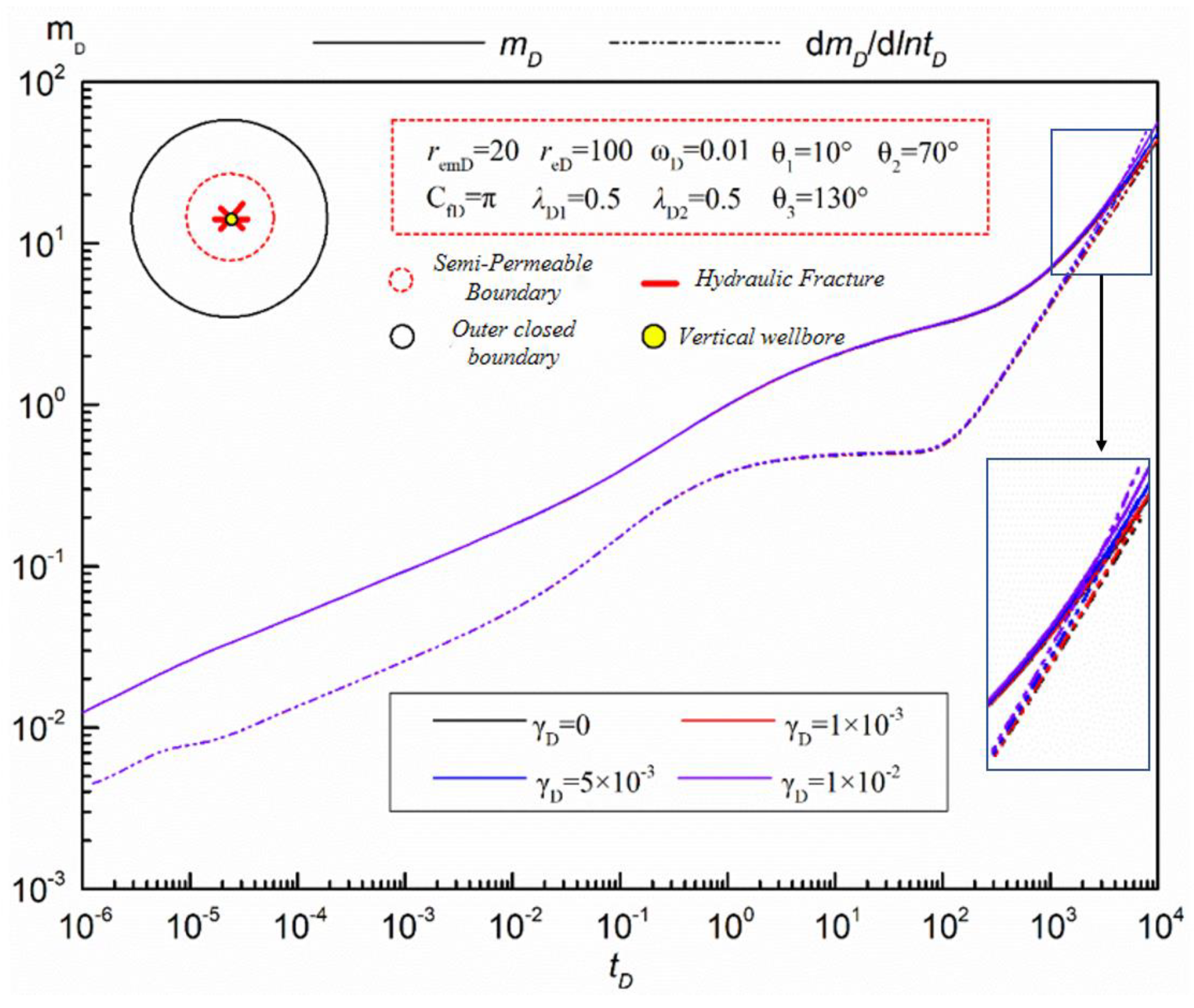
Pressure sensitivity
The influence of pressure sensitivity on pseudo-pressure and pseudo-pressure derivative response curves of a multi-fractured vertical well in a tight sandstone gas reservoir, considering pressure sensitivity and supply boundary, is depicted in Figure 5.
As can be seen in Figure 5, the influence of pressure sensitivity on pseudo-pressure and the pseudo-pressure derivative response curve of the multi-fracture vertical well model is mainly manifested in the middle and late flow stage, that is, the seepage stage after the pressure wave hits the boundary. Due to the increase in pressure sensitivity, the propagation speed of pressure waves in the reservoir becomes slower and slower, resulting in greater pressure loss in the reservoir. It is highlighted in the response curve as follows: the greater the increase in the pressure sensitive coefficient, the larger the pseudo-pressure derivative and the more obvious the upwardness.
(2)
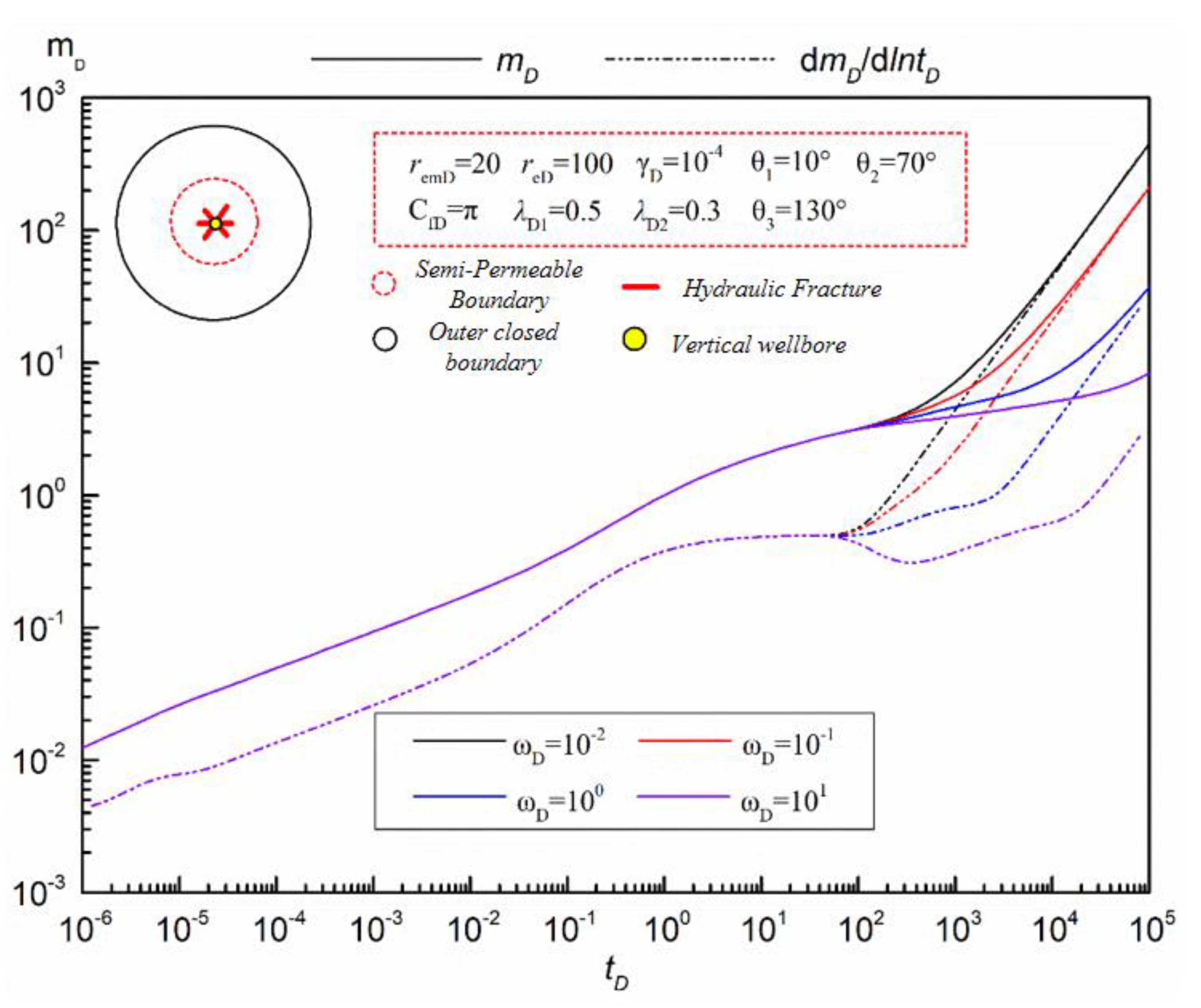
Storage Capacity Ratio of Inner And Outer Areas
Figure 6 shows the influence of reservoir capacity ratio on the response curve of the multi-fractured vertical well model in tight sandstone gas reservoirs. It can be seen that the influence of the variation of the storage capacity ratio in the inner and outer zones on the dimensionless pseudo-pressure and pseudo-pressure derivative curves is mainly manifested in the middle and late seepage stages, that is, the flow section after the middle radial seepage stage. With the increase in the storage capacity ratio in the inner and outer regions, the values of the dimensionless pseudo-pressure and pseudo-pressure derivative become smaller and smaller. The specific impact is as follows: In the channeling phase, with the increase in the internal and external zone capacity ratio, “grooves” gradually appear and gradually become wider and larger. This is mainly because with the increase in the internal and external zone capacity ratio, the reservoir presents the flow characteristics of the two-pore medium reservoir (the flow characteristics of the strong flow ability of the fracture and the flow characteristics of the poor flow ability of the matrix, causing its curve to be similar to that of the two-pore medium). In the boundary control flow stage, with the increase in the storage capacity ratio in the inner and outer regions, the later the pressure wave arrives at the boundary, the later the pseudo-pressure and pseudo-pressure derivative curves coincide on the curve. This is mainly because with the increase in the storage capacity ratio in the outer region, the propagation speed of the pressure wave in the outer region is relatively slow, resulting in the pseudo-pressure and pseudo-pressure derivative curves coinciding later.
(3)
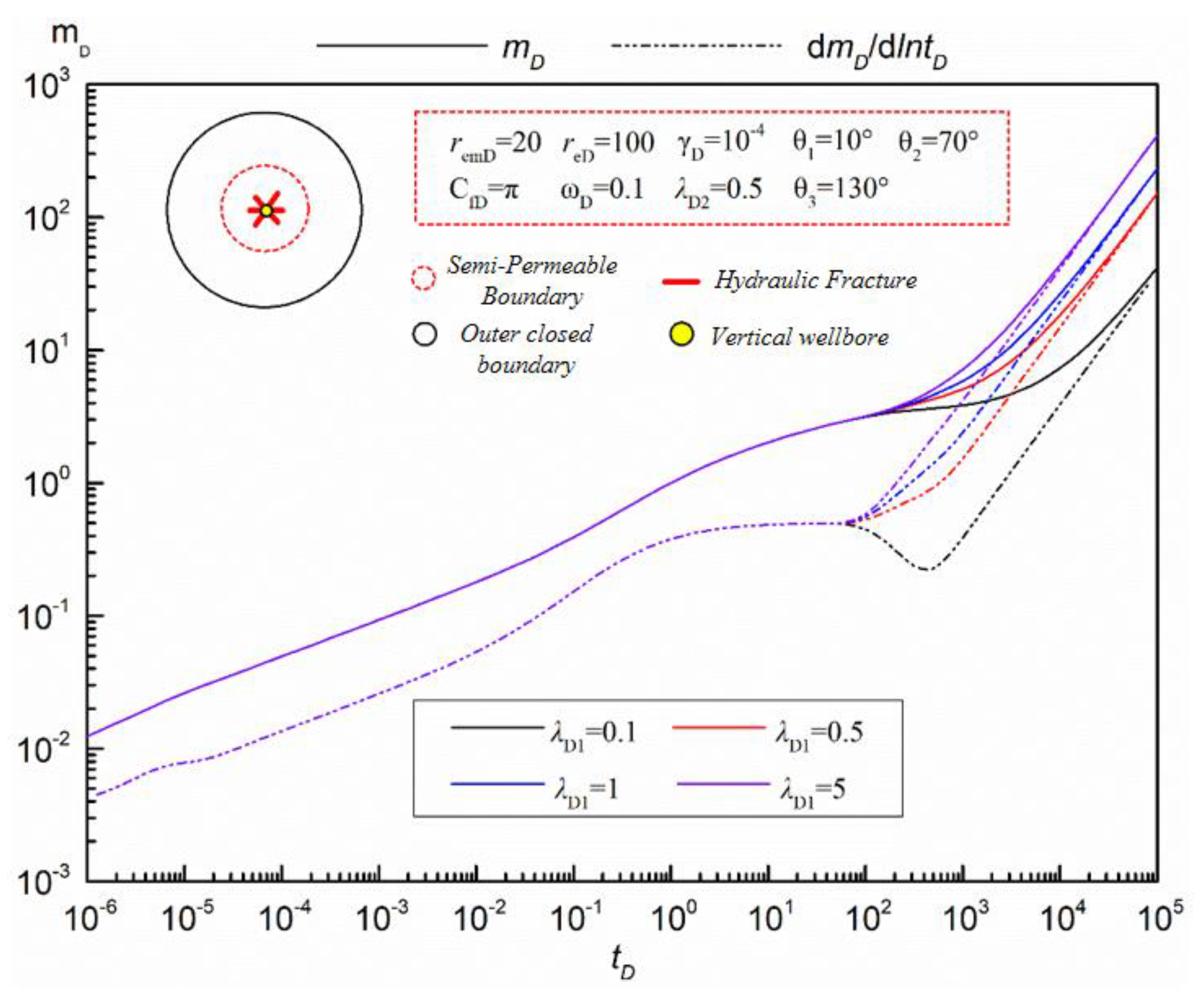
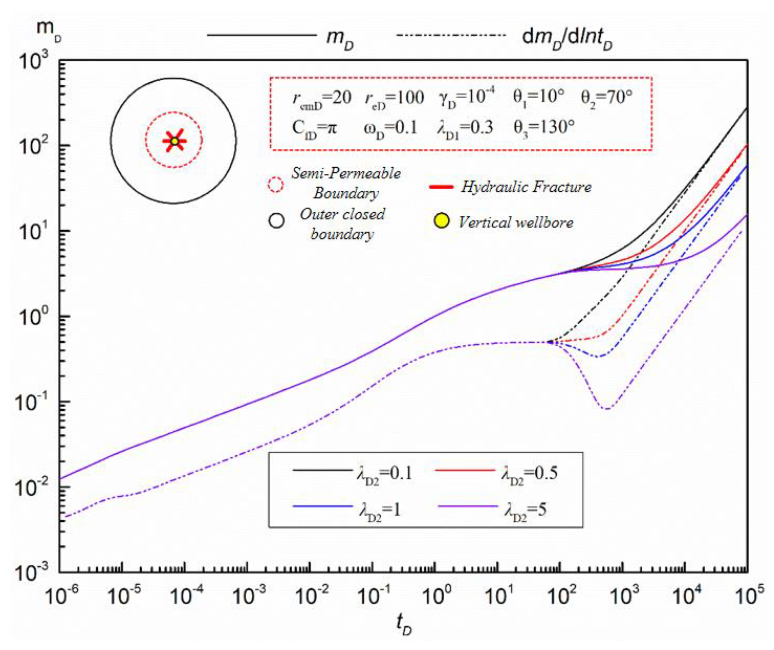
Permeability Coefficient
The influence of inner and outer semi-permeability coefficients on the response curves of multi-fractured vertical wells in tight sandstone gas reservoirs, considering pressure sensitive and supply boundaries, is revealed in Figure 7 and Figure 8, respectively.
Figure 7 focuses on the influence of the inner semi-permeability coefficient on the pseudo-pressure and pseudo-pressure derivative curves of the multi-fracture vertical well model. It can be seen from Figure 7 that the influence of the inner semi-permeability coefficient on the pseudo-pressure and pseudo-pressure derivative curve of the multi-fractured vertical well model of tight sandstone gas reservoirs is mainly manifested in the middle and late seepage stage, that is, the flow stage after the middle radial seepage stage, which is similar to the influence of the storage volume ratio curve of the inner and outer zones. It can be seen from Figure 7 that in the middle and late percolation stages, pseudo-pressure and pseudo-pressure derivatives increase with the increase in the inner semi-permeability coefficient, indicating that the increase in the inner semi-permeability coefficient is not conducive to the rapid development of tight sandstone gas reservoirs. The specific effects are as follows: in the phase of channeling flow, with the increase in the inner zone semi-permeability coefficient, the duration of the channeling flow becomes longer and longer. When the inner zone semi-permeability coefficient increases to a certain value, the “groove” begins to appear. At this time, the fluid flow pattern in the reservoir is similar to the fluid flow pattern in the two-hole medium model. In the boundary control flow stage, with the increase in the semi-permeability coefficient in the inner region, the later the boundary control flow appears, the later the pseudo-pressure and pseudo-pressure derivative curves coincide on the curve.
The influence of the outer semi-permeability coefficient on the curve is also manifested in the middle and late seepage stages, but its influence on the pseudo-pressure and derivative response curve is opposite to that of the inner semi-permeability coefficient on the curve, as Figure 8 shown. The specific influence is shown as follows: in the middle and late percolation stages, the pseudo-pressure and pseudo-pressure derivative gradually decrease with the increase in the outer semi-permeability coefficient, which is a favorable factor for the rapid development of tight sandstone gas reservoirs.
Based on the influence characteristics of the inner and outer zone semi-permeability coefficients on the corresponding curves, it can be seen that the existence of the best inner and outer zone semi-permeability coefficients makes the development of tight sandstone gas reservoirs achieve the best production effect. In addition, during the channeling phase, with the increase in the outer zone semi-permeability coefficient, the “groove” is more obvious, showing a greater depth of “groove” on the curve. In the boundary control flow stage, with the increase in the outer semi-permeability coefficient, the pseudo-pressure and pseudo-pressure derivative curves coincide later.
(4)
Fracture Symmetry
In the actual fracturing process, the two sides of the hydraulic fracture are usually not strictly symmetrical around the wellbore. Therefore, it is of practical significance to study the effect of fracture symmetry on the pseudo-pressure response of multi-fracture vertical wells in tight sandstone gas reservoirs. In this section, the following symmetry factors are defined as follow [33,34,35]:
α = L f l L f s L f l + L f s
When α = 0, it means that the two wings of the fracture are strictly symmetric about the wellbore. When α ≠ 0, it means that the two wings of the fracture are asymmetrical with respect to the wellbore. Therefore, the value range of the symmetry factor is usually [0,1). The more α value approaches 0, it means that the two wings are approximately symmetric about the wellbore, and the larger α value is, the stronger the asymmetry of the two wings. Figure 9 describes the influence of the fracture symmetry factor on the corresponding pseudo-pressure curve of multi-fractured vertical wells in tight sandstone gas reservoirs.
It can be seen from Figure 9 that the influence of fracture symmetry on the pseudo-pressure response curve of multi-fracture vertical wells in tight sandstone gas reservoirs is mainly reflected in the early transition stage, that is, the formation linear see-through stage and the excessive flow stage before radial flow. The specific effects are as follows: In the linear seepage stage of the formation, with the increase in fracture asymmetry (symmetry factor), the pseudo-pressure and pseudo-pressure derivatives become larger and larger, mainly because with the increase in asymmetry, there are differences in the utilization of the two wings of the fracture in tight sandstone gas reservoirs. In the ITD before the radial flow, the pseudo-pressure derivative tends to become slightly smaller with the increase in asymmetry, mainly due to the increase in fracture symmetry, which leads to the formation entering the intermediate radial flow earlier (as shown by the black line in Figure 9). According to the characteristics curves, it can be considered that when the curve of tight sandstone gas reservoirs reverses in its formation of linear flow and intermediate radial flow characteristics, it may be caused by asymmetrical hydraulic fractures. On the whole, in the process of hydraulic fracturing, the hydraulic fractures generated by volume fracturing should be as symmetrical as possible at both ends of the wellbore to avoid the impact of asymmetric fractures on the initial productivity.
(5)
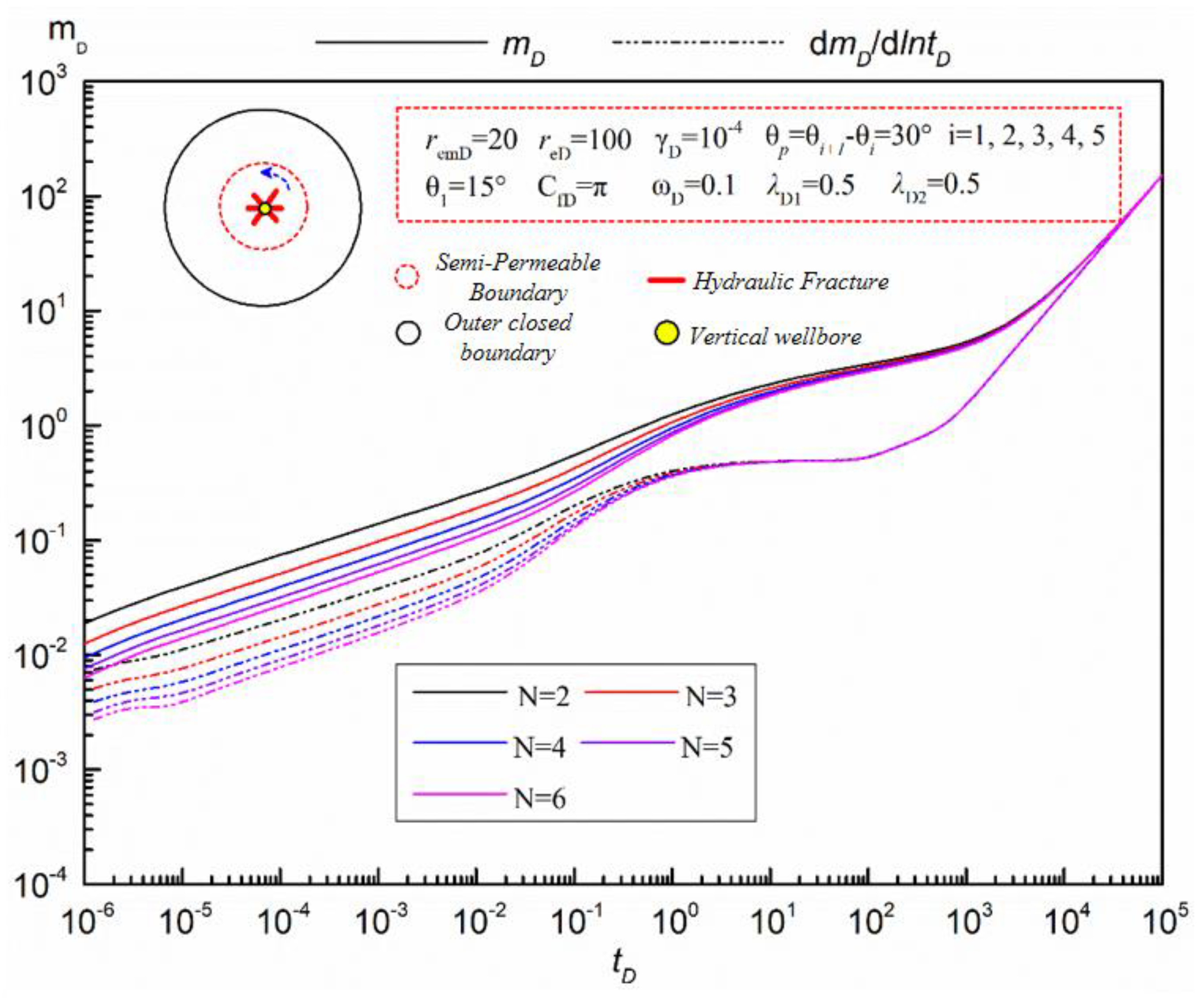
The Number of Fractures
In hydraulic fracture operation, the relationship among total fracture length, fracture number and fracture initiation number is complex; they affect each other, and the specific relationship is affected by rock properties, injection parameters, fracture transmission and other factors. Longer total fracture length may lead to changes in some characteristics of the well test analysis curve, such as fluid transfer properties and permeability estimation. The increase in total fracture length may lead to more significant fluid transfer characteristics in the well test analysis curve, thus affecting the interpretation of reservoir properties. There is a relationship between the number of cracks and the pressure interference effect between cracks. Increasing the number of cracks may lead to an increase in pressure interference between cracks. As the number of cracks increases, fluid transfer and interaction between cracks can lead to changes in productivity and pressure distribution. This may affect the fracture production effect. The number of initiation bars will affect the distribution and morphology of cracks. Different fracture initiation strategies may lead to different fracture distribution, which may affect rock fracture coverage and fracture propagation path, which it turn may affect the fluid transfer and production effect of the reservoir to some extent. In summary, the relationship between total fracture length, fracture number and fracture initiation number is complex, and the influence of these parameters may vary in different reservoirs and operating conditions.
The influence of fracture number on the curve of tight sandstone gas reservoirs is mainly manifested in the early seepage stage, namely, the bilinear seepage stage, fracture interference flow stage and linear formation seepage stage. Figure 10 reveals the influence of fracture number on the pseudo-pressure response curve of multi-fracture vertical wells in tight sandstone gas reservoirs. The specific impact is as follows: In the bilinear seepage stage, with the increase in the number of fractures, the dimensionless pseudo-pressure and pseudo-pressure derivatives become smaller and smaller, but the decreasing trend of pseudo-pressure derivatives gradually weakens when the number of fractures increases, to a certain extent. This is mainly because when the number of fractures increases to a certain value, the interference between adjacent fractures is intensified, and the influence of increasing the number of fractures on improving the gas production of a single well is weakened. In the fracture interference flow stage, with the increase in the number of cracks, the “bulge” is more and more obvious, and the amplitude of the “bulge” becomes larger and larger. This may be due to the discharge area of each crack becoming gradually smaller. Although the angle between cracks is consistent, the crack interference is more and more obvious, resulting in pressure loss caused by the crack interference. The amplitude of the “bulge” on the curve increases. In the linear seepage stage of formation, with the increase in the number of fractures, the pseudo-pressure and derivative of the pseudo-pressure become smaller and smaller, which shows that the curves of the pseudo-pressure and derivative of the pseudo-pressure become closer and even coincide in this seepage stage. In addition, with the increase in the number of fractures, the duration of the intermediate radial flow tends to be shorter and the arrival time of the radial flow becomes later and later.
In general, for multi-fracture vertical wells, although the increase in the number of fractures intensifies the mutual interference between fractures to some extent, with the increase in the number of fractures, it is more and more conducive to production. Therefore, in the process of fracturing construction design, more and more fractures should be generated by hydraulic fracturing.
(6)
Fracture Network
Figure 11 mainly describes the influence of different fracture networks on response curves of multi-fracture vertical sells in tight sandstone gas reservoirs. In this section, the following four fracture networks are mainly considered: first, a symmetrical and equal length fracture network; second, an asymmetrical isometric fracture network; third, a symmetrical unequal length fracture network (two long and one short); fourth, a symmetrical unequal length fracture network (two short and one long). In the above four sewing network situations, sewing network 1 and sewing network 2 form a contrast effect, sewing network 2 and sewing network 3 form a contrast effect, and sewing network 3 and sewing network 4 form a contrast effect.
It can be seen from Figure 11 that the influence of different fracture network arrangements on the quasi-pressure and quasi-pressure derivative curves of the multi-fracture vertical well model in tight sandstone gas reservoirs is mainly concentrated in the linear see-through stage after the fracture interference flow. The specific effects are as follows: In the early linear flow stage, the pseudo-pressure and pseudo-pressure derivative values corresponding to the symmetric isometric fracture network distribution are the smallest, which indicates that the production is higher under the same pressure drop value; so, the production of the symmetric isometric fracture network distribution well is higher in this flow stage. This is mainly because in the early seepage stage, under the condition of symmetrical distribution of the fracture network, the fluid around each fracture can quickly and evenly flow into the wellbore through the fracture. In the linear seepage phase before the radial flow, the pseudo-pressure and derivative values corresponding to the symmetric unequal length (two short and one long) fracture network are smaller, mainly because the existence of longer fractures leads to a larger discharge area corresponding to longer fractures and relatively higher production. However, compared with the early case, the influence of different fracture network arrangements on pseudo-pressure and pseudo-pressure derivative is weak. Therefore, it is suggested that in the process of hydraulic fracturing, the fracture network should be equally distributed as far as possible, which is more conducive to the rapid production of tight sandstone gas reservoirs.

5. Discussion

In this study, we employed the point source function and line source function methods to investigate the unsteady percolation and gas–water two-phase percolation characteristics of tight sandstone gas reservoirs, taking into account the stress-sensitive phenomenon and the presence of discontinuous reservoir boundaries. While our research represents a preliminary exploration of addressing the complex seepage issues in tight sandstone gas reservoirs using a semi-analytical approach, several avenues for further research and improvements become apparent.
(1)
Complex Fracture Networks: One significant aspect that warrants further exploration is the consideration of complex fracture networks after hydraulic fracturing [39,40,41,42,43,44]. In the fracturing process, cross-fracture networks are formed, which can introduce a level of instability in seepage. While our study primarily focused on non-coplanar fractures, it is imperative to delve into the intricate seepage dynamics of cross-fracture networks. Such networks may have unique behaviors and implications for reservoir performance.
(2)
Temporary Closure and Opening of Fractures: Our study currently assumes constant conductivity for artificial fractures. However, in the development of tight sandstone gas reservoirs, the gas–water two-phase seepage can result in the temporary closure and opening of these fractures. Neglecting this dynamic behavior limits the accuracy of our models. Therefore, it is essential to undertake research that emphasizes the temporary closure and opening of fractures during the gas–water two-phase seepage process.
In light of the research conducted in this paper and our insights into the complexities of tight sandstone gas reservoir seepage, the following aspects hold promise for future research:
(1)
Conducting comprehensive studies on cross-fracture networks to understand their influence on seepage stability in tight sandstone gas reservoirs.
(2)
Investigating the mechanisms behind the temporary closure and opening of fractures during gas–water two-phase seepage and its impact on reservoir behavior.
These areas of research can significantly contribute to a more nuanced understanding of tight sandstone gas reservoirs and ultimately enhance our ability to optimize their development strategies.

6. Conclusions

(1)
The phenomenon of superimposed sand body deposition in tight gas reservoirs is common, and the well test curve trends upward and then falls down. This phenomenon is often analyzed based on the constant pressure boundary or radial composite reservoir model, and the inversion results are prone to be misleading. In this paper, a mathematical model of unsteady seepage flow in fractured vertical wells in tight sandstone gas reservoirs is established, which takes into account factors such as stress sensitivity, fracture density and fracture symmetry.
(2)
There are great differences in the seepage mechanism at different stages of complex fracture wells with superimposed sand bodies. In the early linear flow stage, interference between the wings plays a dominant role, which lasts to the middle and later production stages. In the middle seepage stage, the interfracture interference plays a dominant role until the boundary control flow appears. Finally, the interference between the wings is reflected in the curve as a “bulge” in the pseudo-pressure derivative, and the interference between the slots will affect the duration of the first radial flow.
(3)
For tight sandstone gas reservoirs, cross-fracture networks are formed in the fracturing process. However, the fracture network in this paper only considers non-coplanar fractures and does not study the complex seepage of cross-fracture networks. Therefore, the unstable seepage of such complex fracture networks needs further study.

Author Contributions

Conceptualization, Z.Z. and A.X.; methodology, R.G.; validation, L.C., F.K. and X.Z.; formal analysis, X.Z.; writing—original draft preparation, Z.Z.; writing—review and editing, X.Z. All authors have read and agreed to the published version of the manuscript.

Funding

This research received no external funding. The APC was funded by China University of Petroleum (Beijing).

Data Availability Statement

No new data were created.

Conflicts of Interest

The authors declare no conflict of interest.

References

  1. Zou, C.; Yang, Z.; He, D.; Wei, Y.; Li, J.; Jia, A.; Chen, J.; Zhao, Q.; Li, Y.; Li, J.; et al. Theory, technology and prospect of conventional and unconventional natural gas. Pet. Explor. Dev. 2018, 45, 575–587. [Google Scholar] [CrossRef]
  2. Jia, C.; Zou, C.; Yang, Z.; Zhu, R.; Chen, Z.; Zhang, B.; Jiang, L. Significant progress of continental petroleum geology theory in the basins of central and western China. Pet. Explor. Dev. 2018, 45, 546–560. [Google Scholar] [CrossRef]
  3. Feng, Q.; Xu, S.; Xing, X.; Zhang, W.; Wang, S. Advances and challenges in shale oil development: A critical review. Adv. Geo-Energy Res. 2020, 4, 406–418. [Google Scholar] [CrossRef]
  4. Sun, L.; Zou, C.; Jia, A.; Wei, Y.S.; Zhu, R.K.; Wu, S.T.; Guo, Z. Development characteristics and direction of tight oil and gas in China. Pet. Explor. Dev. 2019, 46, 1015–1026. [Google Scholar] [CrossRef]
  5. Jiang, Z.; Pang, X.; Li, F.; Wang, P.; Li, Z.; Li, Y.; Xu, Y. Reservoir-forming mechanism and type division of tight sandstone gas reservoirs. Geol. Soc. China 2013, 267–268. [Google Scholar]
  6. Wang, X. Numerical simulation of low permeability tight sandstone gas reservoir considering stress sensitivity. Petrochem. Appl. 2020, 39, 41–44. [Google Scholar]
  7. Li, G.; Zhu, R. Development status, challenges and concerns of unconventional oil and gas in PetroChina. China Pet. Explor. 2020, 25, 1–13. [Google Scholar]
  8. Zhu, Y. Well Testing and Productivity Prediction of Tight Oil and Gas Reservoirs. Master’s Thesis, University of Science and Technology of China, Beijing, China, 2019. [Google Scholar]
  9. Zhang, F.-Y.; Zou, L.-J.; Rui, Z.-H.; Emami-Meybodi, H.; Ayala, L.F.; Zhang, Z.-X. A two-phase type-curve method with multiscale fluid transport mechanisms in hydraulically fractured shale reservoirs. Pet. Sci. 2023, 20, 2253–2267. [Google Scholar] [CrossRef]
  10. Wang, Y.; Leng, S.; Deng, J.; Lu, X.; Chen, J. Sand body architecture characteristics of lower Member of Hehe 8 in Western Sulige Gas Field. Inn. Mong. Petrochem. Ind. 2022, 48, 108–113. [Google Scholar]
  11. Kuchuk, F.; Biryukov, D.; Fitzpatrick, T.; Morton, K. Pressure transient behavior of horizontal wells intersecting multiple hydraulic and natural fractures in conventional and unconventional unfractured and naturally fractured reservoirs. In Proceedings of the SPE Annual Technical Conference and Exhibition, Houston, TX, USA, 28–30 September 2015. Paper SPE 175037. [Google Scholar]
  12. Wang, S.; Qin, C.; Feng, Q.; Javadpour, F.; Rui, Z. A framework for predicting the production performance of unconventional resources using deep learning. Appl. Energy 2021, 295, 117016. [Google Scholar] [CrossRef]
  13. Li, J. Research on Dynamic Analysis of Fractured Horizontal Well. Ph.D. Thesis, China University of Geosciences, Beijing, China, 2005. [Google Scholar]
  14. Wan, J.; Aziz, K. Semi-analytical well model of horizontal wells with multiple hydraulic fractures. Soc. Pet. Eng. J. 2002, 7, 437–445. [Google Scholar] [CrossRef]
  15. Fan, D.; Yao, J.; Wang, Z.; Zhang, G. Interpretation of well testing of fractured horizontal Wells based on different dip angles. Res. Prog. Hydrodyn. 2009, 6, 705–712. [Google Scholar]
  16. Zerar, Z.; Bettam, Y. Interpretation of multiple hydraulically fractured horizontal wells in closed systems. In Proceedings of the Canadian International Petroleum Conference, Calgary, AB, Canada, 8–10 June 2004. [Google Scholar]
  17. Meng, M.; Chen, Z.; Liao, X.; Wang, J.; Shi, L. A well-testing method for parameter evaluation of multiple fractured horizontal wells with non-uniform fractures in shale oil reservoirs. Adv. Geo-Energy Res. 2020, 4, 187–198. [Google Scholar] [CrossRef]
  18. Cui, G.; Pei, S.; Rui, Z.; Dou, B.; Ning, F.; Wang, J. Whole process analysis of geothermal exploitation and power generation from a depleted high-temperature gas reservoir by recycling CO2. Energy 2021, 217, 119340. [Google Scholar] [CrossRef]
  19. Zhang, L.; Kou, Z.; Wang, H.; Zhao, Y.; Dejam, M.; Guo, J.; Du, J. Performance analysis for a model of a multi-wing hydraulically fractured vertical well in a coalbed methane gas reservoir. J. Pet. Sci. Eng. 2018, 166, 104–120. [Google Scholar] [CrossRef]
  20. Wang, H.; Kou, Z.; Guo, J.; Chen, Z. A semi-analytical model for the transient pressure behaviors of a multiple fractured well in a coal seam gas reservoir. J. Pet. Sci. Eng. 2021, 198, 108159. [Google Scholar]
  21. Zou, W.; Yu, H.; Guo, J.; Shi, M. Fractal well test model for multi-wing fractured vertical well with finite conductivity in the coal bed methane reservoir. J. Northeast. Pet. Univ. 2021, 45, 102–110. [Google Scholar]
  22. Zhao, K.; Du, P. Performance of horizontal wells in composite tight gas reservoirs considering stress sensitivity. Adv. Geo-Energy Res. 2019, 3, 287–303. [Google Scholar] [CrossRef]
  23. Bouchaala, F.; Ali, M.Y.; Matsushima, J. Estimation of seismic attenuation in carbonate rocks using three different methods: Application on VSP data from Abu Dhabi oilfield. J. Appl. Geophys. 2016, 129, 79–91. [Google Scholar] [CrossRef]
  24. Jouini, M.S.; Bouchaala, F.; Riahi, M.K.; Sassi, M.; Abderrahmane, H.; Hjouj, F. Multifractal analysis of reservoir rock samples using 3D X-ray micro computed tomography images. IEEE Access 2022, 10, 67898–67909. [Google Scholar] [CrossRef]
  25. Yao, J.; Yin, X.; Fan, D.; Sun, Z. Three-linear flow test model for fractured horizontal Wells in low permeability reservoir. Oil Gas Well Test. 2011, 20, 1–5. [Google Scholar]
  26. Wang, X.; Luo, W.; Hou, X.; Wang, J. Unsteady pressure analysis of multi-stage fractured horizontal well in rectangular reservoir. Pet. Explor. Dev. 2014, 41, 74–78. [Google Scholar] [CrossRef]
  27. Amini, S. Development and Application of the Method of Distributed Volumetric Sources to the Problem of Unsteady-State Fluid Flow in Reservoirs. Ph.D. Thesis, Texas A&M University, College Station, TX, USA, 2007. [Google Scholar]
  28. Bear, J.; Braester, C.; Menier, P.C. Effective and relative permeabilities of anisotropie porous media. Transp. Porous Media 1987, 2, 301–316. [Google Scholar] [CrossRef]
  29. Hantush, M.N. Non-steady Green’s functions for an infinite strip of leaky aquifer. Trans AGU 1955, 36, 101–104. [Google Scholar] [CrossRef]
  30. Boussila, A.K.; Tiab, D.; Owayed, J. Pressure Behavior of Well Near a leaky Boundary in Heterogeneous Reservoirs. J. Pet. Technol. 2003, 27, 89–96. [Google Scholar]
  31. Rahman, N.M.; Miller, M.D.; Mattar, L. Analytical Solution to the Transient-Flow Problems for a Well Located near a Finite-Conductivity Fault in Composite Reservoirs. Soc. Pet. Eng. 2003, 96, 120–139. [Google Scholar]
  32. Escobar, F.; Fahes, M.; Gonzalez, R.; Pinchao, D.M.; Zhao, Y.L. Determination of Reservoir Drainage Area for Constant-Pressure Systems by Conventional Transient Pressure Analysis. ARPN J. Eng. Appl. Sci. 2015, 10, 5193–5199. [Google Scholar]
  33. Abdelaziz, B.; Tiab, D. Pressure Behaviour of a Well between Two Intersecting Leaky Faults. In Proceedings of the Canadian International Petroleum Conference, Calgary, AB, Canada, 8–10 June 2004. Paper PETSOC-2004-209. [Google Scholar]
  34. Jongkittinarukorn, K.; Tiab, D.; Escobar, F.H. Interpretation of Horizontal Well Performance in Complicated Systems by the Boundary Element Method. Paper SPE 50437. In Proceedings of the SPE International Conference on Horizontal Well Technology, Calgary, AB, Canada, 1–4 November 1998. [Google Scholar]
  35. Wang, Y.; Ayala, L.F. Explicit Determination of Reserves for Variable-Bottomhole-Pressure Conditions in Gas Rate-Transient Analysis. Soc. Pet. Eng. 2020, 25, 1936–1945. [Google Scholar] [CrossRef]
  36. Zhu, W.; Yang, X. Action mechanism of water on the gas seepage capacity in tight gas reservoir. Spec. Oil Gas Reserv. 2019, 26, 128–132. [Google Scholar]
  37. Liu, P.; Guo, H.; Zhang, X.; Shen, R.; Li, H. Experimental Study on Mechanism of Water Sensitivity and Water Lock Damage in Tight Gas Reservoir. Bull. Sci. Technol. 2019, 35, 103–108. [Google Scholar]
  38. Ouyang, L.B.; Petalas, N.; Arbabi, S.; Schroeder, D.E.; Aziz, K. An experimental study of single-phase and two-phase fluid flow in horizontal wells. In Proceedings of the SPE Western Regional Meeting, Bakersfield, CA, USA, 10–13 May 1998. Paper SPE 46221. [Google Scholar]
  39. Luo, S.; Ding, C.; Cheng, H.; Zhang, B.; Zhao, Y.; Liu, L. Estimated ultimate recovery prediction of fractured horizontal wells in tight oil reservoirs based on deep neural networks. Adv. Geo-Energy Res. 2022, 6, 111–122. [Google Scholar] [CrossRef]
  40. Bunger, A.P.; Zhang, X.; Jeffrey, R.G. Parameters affecting the interaction among closely spaced hydraulic fractures. SPE J. 2012, 17, 292–306. [Google Scholar] [CrossRef]
  41. Carter, B.J.; Desroches, J.; Ingraffea, A.R.; Wawrzynek, P.A. Simulating fully 3D hydraulic fracturing. Model. Geomech. 2000, 200, 525–557. [Google Scholar]
  42. Asadi, M.B.; Zendehboudi, S. Evaluation of productivity index in unconventional reservoir systems: An extended distributed volumetric sources method. J. Nat. Gas Sci. Eng. 2019, 61, 1–17. [Google Scholar] [CrossRef]
  43. Wu, Z.; Cui, C.; Jia, P.; Wang, Z.; Sui, Y. Advances and challenges in hydraulic fracturing of tight reservoirs: A critical review. Energy Geosci. 2022, 3, 427–435. [Google Scholar] [CrossRef]
  44. Chu, H.; Zhang, J.; Zhang, L.; Ma, T.; Gao, Y.; Lee, W.J. A new semi-analytical flow model for multi-branch well testing in natural gas hydrates. Adv. Geo-Energy Res. 2023, 7, 176–188. [Google Scholar] [CrossRef]
Figure 1. Superimposed pattern of channel sand bodies in gas reservoir X.
Energies 16 07275 g001
Figure 2. Schematic diagram of multi-fractured vertical wells model in tight sandstone gas reservoirs.
Energies 16 07275 g002
Figure 3. Comparison of multi-fracture vertical wells in tight sandstone gas reservoirs [26].
Energies 16 07275 g003
Figure 4. Pressure response curve characteristics of multi-fracture vertical wells in tight sandstone gas reservoirs.
Energies 16 07275 g004
Figure 5. Influence of pressure sensitivity on pressure response curve of multi-fracture vertical wells.
Energies 16 07275 g005
Figure 6. Influence of reservoir volume ratio on pressure response curve of multi-fractured vertical wells.
Energies 16 07275 g006
Figure 7. Influence of permeability coefficient on pressure response curve of multi-fracture vertical wells (λD1).
Energies 16 07275 g007
Figure 8. Influence of permeability coefficient on pressure response curve of multi-fracture vertical wells (λD2).
Energies 16 07275 g008
Figure 9. Influence of fracture symmetry on pressure response curve of multi-fracture vertical wells.
Energies 16 07275 g009
Figure 10. Influence of fracture number on pressure response curve of multi-fracture vertical wells.
Energies 16 07275 g010
Figure 11. Influence of different fracture networks on pressure response curves of multi-fracture vertical wells.
Energies 16 07275 g011
Disclaimer/Publisher’s Note: The statements, opinions and data contained in all publications are solely those of the individual author(s) and contributor(s) and not of MDPI and/or the editor(s). MDPI and/or the editor(s) disclaim responsibility for any injury to people or property resulting from any ideas, methods, instructions or products referred to in the content.

