
A Study on the Permeability and Damage Characteristics of Limestone under Stress–Seepage Coupling Conditions

1
School of Architecture and Civil Engineering, Xihua University, Chengdu 610039, China
2
College of Water Resources and Hydropower, Sichuan University, Chengdu 610065, China
*
Author to whom correspondence should be addressed.
Energies 2023, 16(19), 6899; https://doi.org/10.3390/en16196899
Submission received: 28 August 2023
/
Revised: 12 September 2023
/
Accepted: 27 September 2023
/
Published: 30 September 2023
(This article belongs to the Collection Flow and Transport in Porous Media)
Abstract
:With the increase in energy demand, energy engineering has gradually developed to go deeper, accompanied by a complex geological environment, such as the coupling of stress and seepage. Limestone is widely found in underground rock engineering, and its stress–seepage coupling characteristics have a great influence on the safety and stability of related engineering projects. In order to study the permeability characteristics and damage evolution of limestone during the deformation and failure process under stress–seepage coupling conditions, permeability and acoustic emission tests on limestone were performed in this paper. The results showed that: the stress–strain curve demonstrated periodicity, as did the permeability change. The change in permeability in different deformation stages of axial strain and lateral strain was similar, but it was more appropriate to reflect the permeability evolution in terms of lateral strain. The permeability of the limestone slightly decreased in the volumetric compression stage, and tended to saturate after a sudden increase in the expansion stage. The presence of the confining pressure reduced the permeability of the rock. In the process of limestone deformation and failure, the level of acoustic emission activity can reflect the degree of fracture development. The permeability characteristics and acoustic emission characteristics had a good corresponding relationship. The greater the confining pressure, the higher the acoustic emission activity. The deformation and damage process of limestone experienced three stages: damage stable growth, damage acceleration development, and damage saturation.
1. Introduction
Energy is an important material basis for the survival, production, and development of society. With the rapid development of the economy, energy development and underground geotechnical engineering have been developed to deeper and deeper, and the geological environment has become more and more complex. In particular, the groundwater seepage in fractures has a great influence on the stability of rock mass [1,2]. To ensure the safety and stability of geotechnical engineering, the permeability characteristics of rocks under different stress conditions have become an important research topic in recent years [3,4,5]. As is known, the rock permeability and stress condition influence each other. A change in the stress condition will change the structure of the rocks, causing permeability changes. Meanwhile, the seepage will weaken the mechanical properties of the rocks, causing engineering safety problems [6,7,8]. Therefore, studying the permeability characteristics of rocks under stress–seepage coupling conditions can help to provide a theoretical basis for the prevention and control of rock engineering accidents.
In recent years, the permeability problems of various engineering rocks have been experimentally studied by many scholars. Because the stress of rocks in deep underground engineering is frequently a dynamic load that changes over time, based on triaxial compression tests and triaxial cyclic loading tests, scholars have performed a lot of research on various types of rocks in terms of permeability characteristics, and obtained the deformation, strength, and permeability evolution laws of different rocks [9,10,11,12,13,14,15]. By analyzing the seepage–stress coupling mechanism of sandstone under different confining pressures, the variation law of permeability with a stress–strain curve was obtained, finding that permeability is a function of axial stress and strain [16,17,18,19], and the permeability in different deformation stages of sandstone shows different characteristics [20]. In addition, the axial stress loading path also had an effect on permeability. The skeleton particles underwent irreversible deformation due to the axial stress’s cyclic loading and unloading, which resulted in irreversible phenomena of permeability [21]. Following the peak of the rock strength, the permeability increases dramatically, which is congruent with the change in the volumetric strain. In general, previous studies have focused on rocks with a high permeability, and less research has been performed on the permeability of rocks with a poor fracture connectivity [22]. Generally, rocks with a low porosity and permeability are a good material for underground storage. However, in deep underground engineering, high stress and high water pressure cause rock deformation and failure easier, which further changes the permeability of rocks. Since low-permeability limestone is one of the typical rocks used in underground engineering, researching the permeability law of limestone during its deformation and damage process can offer a theoretical foundation for the creation and use of underground engineering.
Rock fracture initiates and develops under stress to produce new damage, leading to permeability changes. Stress is the external cause of rock permeability changes, and the root cause of rock permeability changes is the result of its internal structural damage evolution [23]. An AE (acoustic emission) event is an elastic wave released when a microcrack occurs in the internal structure of a material, which is widely used to investigate the damage mechanism of rocks or other materials [24,25,26,27,28]. As a dynamic nondestructive monitoring method that can monitor the development of internal damage in materials in real time, the mechanism between rock permeability characteristics and damage can be better characterized by acoustic emission technology [29]. Conventional triaxial compression tests, acoustic emission monitoring, and penetration tests are frequently combined in studies [30]. For the most part, these studies combine traditional triaxial compression, acoustic emission monitoring, and permeation tests to investigate the relationship between stress–strain and permeability, and acoustic emission characteristics and permeability, as well as to reveal the deformation properties, permeability revolution, and acoustic emission characteristics of different types of rocks [31,32,33,34]. Through an analysis and discussion of fine sandstone’s permeability and acoustic emission properties throughout the damage process, it has been discovered that there is some correlation between permeability, acoustic emission parameters, stress, and volumetric strain [35,36]. An abrupt change in lateral deformation corresponds to an abrupt change in permeability, which can effectively reflect the characteristics of permeability changes [37]. It is important to study the relationship between the permeability and deformation characteristics of limestone, since low-permeability rocks are a desirable option for underground engineering.
In this paper, permeability tests of limestone under stress–seepage coupling conditions were carried out using the hydro-mechanical multi-field coupling test system. Considering that the steady-state method for measuring the stable volumetric flow velocity of low-permeability rocks is time-consuming and has a low accuracy, the transient method was adopted. Based on the experimental results, the following contents were analyzed and discussed: (i) the stress–strain properties, permeability changes, and their corresponding relationships in the deformation and failure process of limestone under stress and seepage coupling conditions; (ii) the acoustic emission characteristics and their relationship with permeability were studied using acoustic emission technology; and (iii) the damage variable was defined based on acoustic emission characteristics, and the internal reasons for the permeability changes during the deformation and failure process of limestone were discussed from the perspective of damage evolution.
2. Test Conditions
2.1. Specimen Preparation
This limestone serves as the roof and floor rock in coal mines. Limestone without obvious cracks were selected as the specimens, and the specimens were processed into standard cylindrical specimens with a diameter of 50 mm and a height of 100 mm by coring and cutting. The accuracy of each specimen met the standard of the Engineering Rock Test Method Standard [38] and the ISRM (International Society for Rock Mechanics) recommendations. Considering that the end of the specimen was bound by the friction force at both ends of the bearing poles of the testing machine, the end regions of the specimens were not as easy to damage as the middle regions when the stress reached the ultimate bearing capacity of the rock specimen, resulting in not being able to obtain the failure surface distributed in the middle of the specimen and the seepage characteristics of the failure surface in the post-peak stage (Figure 1a). Therefore, blind holes were drilled to connect the fracture surface in the middle of the specimen and the testing machine to form a specimen–machine seepage channel system (Figure 1b), so that the water entered the fracture in the specimen from the inlet and formed the seepage in the specimen in the post-peak stage.
2.2. Experimental Apparatus and Testing Scheme
The triaxial compression tests and penetration tests were conducted using the MTS815 Flex Test GT rock mechanics test system, and a PCI-II acoustic emission test workstation was equipped for simultaneous acoustic emission monitoring. During the tests, the stress and deformation were measured using high-precision sensors, and the loading rate was accurate. The parameters measured in the tests were automatically collected and stored by a computer.
To obtain the post-peak stress–strain curves and permeability characteristics, stress control was used when the axial stress was less than 75% of the peak stress, and strain control was used thereafter. The permeability of the penetration test was measured using the transient method. The principle of transient method is as follows: firstly, the confining pressure, water pressure, and axial pressure were applied to the specimen to the preset value (always keeping the confining pressure greater than the water pressure). Then, the water pressure was reduced at one end to form the permeation pressure difference (∆P) to cause seepage in the rock specimen. The permeability was calculated according to the decay and time of the pressure difference. The test equipment and working mode are shown in Figure 2.
The related processes of the test were as follows: the specimen was protected with heat-shrinkable film to ensure that the oil in the pressure chamber separated from the water, which was placed in the strain gauge. At the same time, eight AE sensors were mounted on the triaxial chamber’s exterior wall to monitor the whole process of the penetration test. Then, the desired confining pressure value (8, 12, and 16 MPa) was applied to the limestone specimen, and the water pressure was loaded to 6 MPa after the confining pressure was stable. After this, the axial loading was applied. According to the stress–strain curve obtained through the conventional triaxial test, 10 permeability measuring points were set up and measured in turn. When the test entered the residual stage, it was stopped immediately.
3. Experimental Results and Analysis
3.1. Permeability Calculation Method
To analyze the permeability characteristics, the permeability should be calculated first, assuming that the rock is a pore medium [39], water is incompressible, and the flow of the water in the rock belongs to laminar flow, which conforms to Darcy’s law. According to Darcy’s law formula:
After substituting q and i, the conversion yields k:
Then, the permeability K is:
where V is the seepage velocity (m/s); q is the seepage volume (m3/s); ρ is the density of water (1 g/cm3); A is the cross-sectional area of the specimen (m2); k is the permeability coefficient (m/s); VΔ is the volume of the pressure-stabilizing vessel V1 or V2 (cm3); Δt is the time difference (s); i is the hydraulic gradient; Δh is the head loss (m); L is the seepage length (m); PV1 − PV2 is the differential pressure (MPa); γω is the heaviness of water (10 kN/m3); K is the permeability (m2); and α is the pore fluid viscosity. At 20 °C, the viscosity of water is 10−3 Pa·s.
It can be known from the incompressibility of liquid ():
where β is the pore fluid compression coefficient (4.53 × 10⁻¹⁰ Pa−1) and PV is the pressure of the stabilizing vessel (MPa). The stabilizing vessels are V1 and V2, and V1 = V2.
It can be obtained from Equations (1)–(4) that:
Substituting Equation (7) into Equation (6) gives:
Assuming that ΔPi = PV1 − PV2 is the initial differential pressure of the permeability measuring point and ΔPf = PfV1 − PfV2 is the final. The permeability expression of the transient method can be obtained by integrating Equation (7):
3.2. Permeability Evolution in Whole Process
The stress–strain curves and permeability–strain curves are shown in Figure 3. The permeability changed in stages with the stress–strain curve during the deformation and failure process of the limestone. Compression stage (OA): the initial fractures of the specimen were compressed, the seepage channel was blocked, and the permeability decreased slightly; Linear elastic deformation stage (AB): the strain increased linearly with the stress, which satisfied Hooke’s law, no penetrating seepage channel was formed inside the specimen at a smaller stress, and the permeability increased slightly; Yield stage (BC): the axial deformation increased rapidly and the permeability increased significantly. When the stress reached the peak, the permeability began to increase sharply; Damage stage (CD): with macroscopic damage to the specimen’s internal fissure formation through the surge channel, the permeability suddenly increased to the peak. Since the permeability was increased under the condition of fracture expansion, the peak permeability lagged behind the peak stress; and Residual stage (DE): the fragmented particles after specimen destruction blocked the local fissures so that the post-peak permeability decreased and then tended to be smooth.
The permeability–lateral strain curves at different deformation stages were similar to the permeability–axial strain curves. However, compared to the axial strain curve, the lateral strain curve showed more sensitivity. The lateral elastic strain was smaller than the axial elastic strain, and the increase in the lateral strain before yielding was much smaller than the increase in the axial strain, which was similar to the variation law of permeability. When the specimen approached failure, the lateral strain increased sharply and suddenly changed with the permeability. Therefore, it is more appropriate to reflect the permeability evolution in terms of lateral strain.
Permeability is closely related to rock deformation in the process of deformation and failure. As shown in Figure 4, when the confining pressure was 8 MPa, with an increase in the axial load, the rock was initially dominated by axial strain (ε1 > |ε3|), at which point the permeability initially decreased slightly and then slowly increased. Later, the lateral strain increased rapidly and the permeability also increased rapidly. Eventually, the rock became dominated by lateral deformation (ε1 ˂ |ε3|) until failure; when the confining pressures were 12 MPa and 16 MPa, the rock showed mainly axial deformation. The axial strain initially increased quickly, then continued to grow steadily, and the change in permeability was consistent with an 8 MPa confining pressure. The deformation of the rock was determined by both lateral and axial directions. To accurately analyze the effect of the rock deformation damage on the permeability, the volumetric strain was used to describe the relationship between the rock expansion characteristics and the permeability. The expressions are as follows:
where: εv is the volume strain; ε1 is the axial strain; and ε3 is the lateral strain.
Figure 5 shows that the rock underwent volume compression and volume expansion during its deformation and failure process. During the volume compression stage, the volume strain increased steadily with the deviatoric stress, while the permeability decreased first and then increased. At the initial stage of the application of deviational stress, the pores and micro-cracks inside the rock specimen were compressed, resulting in the volume compression and permeability reduction. Then, with an increase in the deviatoric stress, micro-cracks continued to expand and new cracks occurred, resulting in a slow increase in permeability. In the smaller deformation range of the specimen from compression to expansion, macroscopic damage occurred in the specimen and the permeability increased steeply, after which, the volume strain increased linearly with the lateral and axial strains, while the permeability showed “relative saturation”.
The minimum permeability at different confining pressures, permeability at the expansion point and the corresponding volume strains, and permeability at expansion zero (εv = 0) are shown in Table 1. The minimum permeability and the permeability at the expansion point decreased with the confining pressure; the volume strains of the minimum permeability were smaller than the volume strains at the compression limit under different confining pressures. The above results showed a significant confining pressure effect on the volumetric strain and permeability of the limestone, indicating that confining pressure had a limiting effect on the initiation and development of cracks.
3.3. AE Characteristics
Fracture initiation and development inside the specimen would change the circulation of seepage channels and affect the change in permeability. The energy released during the development of fractures can be reflected by the level of acoustic emission activity. Therefore, the acoustic emission technique can be used to study the evolution of rock permeability.
Given the ringing count and energy as two characteristic parameters of acoustic emission signals, they can reflect the AE characteristics and laws in the rock deformation and failure process to a certain extent. Therefore, the ringing count, energy per unit time (i.e., the ringing count rate and energy rate), cumulative ringing count, and cumulative energy were chosen as the research parameters to analyze the whole process and time effect evolution characteristics of the acoustic emission.
The relationship curves of the deviatoric stress, acoustic emission characteristics (the cumulative ringing count and energy), and permeability with time under different confining pressures are given in Figure 6. Among them, the cumulative ringing count (N) represents the number of times that the fracture crossed the threshold signal during the development process, which reflects the degree of fracture development. Figure 6 shows that the permeability characteristics during the deformation of limestone showed a good correlation with the acoustic emission characteristics. The development of fractures before yielding was slow, and the seepage channels were mainly composed of primary fractures and a few new fractures. At this stage, the permeability changed little and the acoustic emission activity was low. Fractures in the yielding stage began to develop, the released energy gradually rose, the cumulative ringing count increased and became larger, and the permeability increased rapidly at the end of the yielding phase. Fractures in the failure stage developed rapidly and penetrated, forming a penetrating seepage channel, the permeability increased sharply to the peak, the energy increased significantly, and the cumulative ringing count growth rate reached the peak. In the residual stage, the fracture development slowed down, the acoustic emission activity returned to calm, and the energy and ringing count were relatively stable. The higher the confining pressure and energy during the whole process of deformation damage, the higher the peak cumulative ring count. This was because the higher the confining pressure, the greater the rock strength, the greater the strain energy accumulated during the deformation and damage, the more times the threshold signal was crossed by the fracture initiation and development, and the higher the energy released.
3.4. Damage Variable Based on Acoustic Emission
Rock damage has a significant impact on its overall mechanical properties and permeability characteristics [40,41]. As one of the best methods for reflecting the actual deformation and damage of rock, the characteristic parameters of acoustic emission: ringing count and energy, can reflect the characteristics and laws of the acoustic emission during the deformation and damage of rock, to a certain extent. After studying the material damage evolution using the acoustic emission technique, Liu et al. [42] pointed out that the ringing count is proportional to the strain energy released by the material, and concluded that the ringing count can better describe the change in the material properties. Therefore, the limestone damage characteristics were analyzed using the cumulative ringing count.
According to the definition of continuous damage mechanics, the damage variable D can be defined as the ratio of the total area of pores appearing in the cross-section of the material after the damage is produced to the original cross-sectional area of the material, and its expression is:
where: Ad is the total area of pores in the cross-section of the material after the damage and A0 is the original undamaged cross-sectional area of the material. When Ad = A0, the material is in a state of complete damage, and when Ad = 0, the material is in a state of no damage. Rocks under complex stress conditions generally have initial damage, so when the original cross-sectional area of the rock with damage is A, the damage variable can be redefined as:
When A = A0, the initial damage is defined as:
According to the results of the acoustic emission: when there are fewer fractures, the acoustic emission activity is low. When a fracture begins to fuse and develop, the released energy begins to gradually increase, the cumulative ringing count increases, and the acoustic emission activity increases. If the cumulative ringing count for the complete destruction of the entire cross-section of the rock is Nf, then the ringing count per unit area of destruction N1 is:
When the damage area reaches Ad, the cumulative ringing count Nd is:
Since the initial damage of the intact rock is small, set D0 = 0. Equation (13) can be changed to:
Combined with the test parameters, the damage variables during the deformation and failure process of limestone were calculated using Equation (15).
4. Discussion
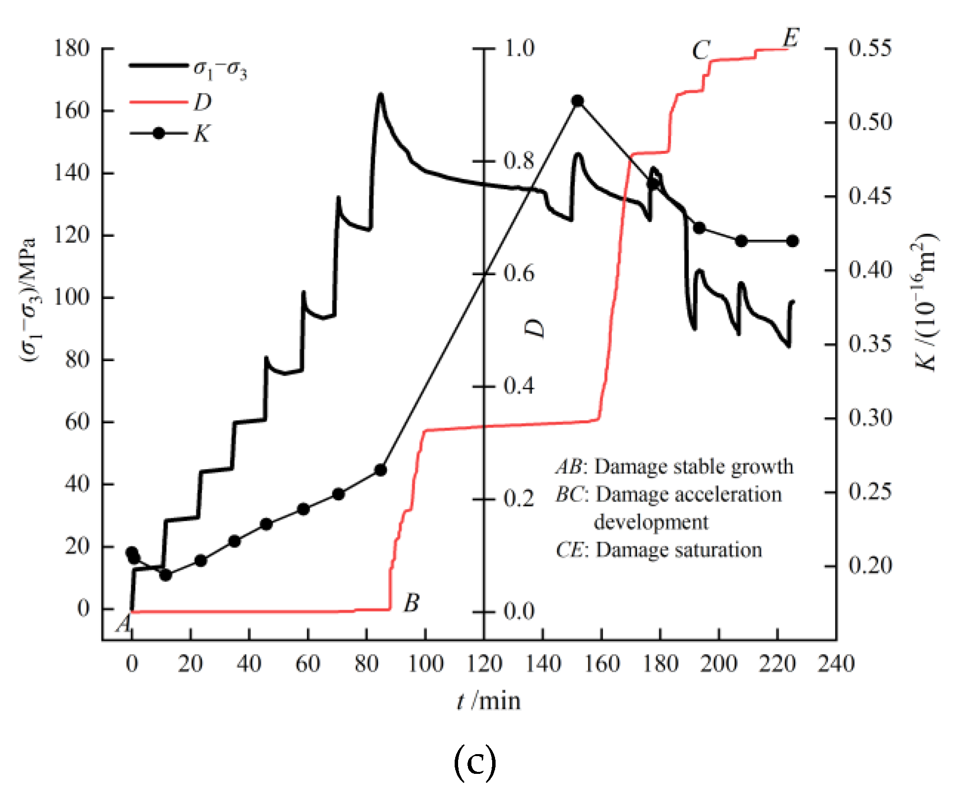
As we know, the internal cause of rock deformation and failure is the generation, development, and accumulation of internal defects during the process of stress application, which is also the key to affecting the connectivity of seepage channels and rock permeability. The damage variable defined by acoustic emission can quantitatively characterize the development of internal defects inside rocks, and further discuss the root cause of permeability changes in the process of rock deformation and failure. Based on the above experimental analysis, Figure 7 shows the relationship curves of the deviatoric stress, damage variables, and permeability with time under different confining pressures. According to the changing trend of damage variables, the damage evolution of limestone in the failure process was divided into three stages: damage stable growth (AB), damage acceleration development (BC), and damage saturation (CE). In the damage stable growth stage, fractures in the specimen gradually initiated and developed, which caused less damage. At this stage, the low connectivity of the seepage channel resulted in the seepage being mainly pore seepage, so the permeability did not change much. In the damage acceleration stage, the fractures rapidly expanded and penetrated, which accelerated the damage accumulation and formed a macroscopic fracture surface, causing the permeability to increase sharply in the penetrated seepage channels. In the damage saturation stage, the specimen was basically deformed, and the permeability tended to be stable. In the damage process of limestone, the permeability change with damage characteristics corresponds well with the permeability change with the deformation characteristics.
5. Conclusions
Permeability tests and acoustic emission tests were conducted on limestone specimens to analyze their permeability and damage characteristics under stress–seepage coupling conditions. To ensure that water could penetrate through the fractures, the ends of the specimens were drilled, so that the test results could better reflect the permeability characteristics of the limestone. The results were as follows:
- (1)
- The limestone permeability showed consistent stage characteristics with the strain. Compared to the axial strain, the permeability and lateral strain had a better consistency. From the perspective of volume strain, the permeability of the limestone decreased slightly in the volume compression stage. During the transition from compression to expansion, the permeability increased sharply to the peak value, and then the seepage was mainly fracturing seepage and showed ‘relative saturation’. The existence of confining pressure hindered the initiation and development of fractures and reduced the permeability of the rock.
- (2)
- The permeability characteristics during the deformation and damage of the limestone had a good correspondence with the acoustic emission characteristics. The permeability was small before yielding, increased slowly in the yielding stage, increased sharply to the peak in the damage stage, and tended to be stable in the residual stage. The acoustic emission activity increased throughout the process, and calm resumed in the residual phase. The higher the confining pressure was, the greater the acoustic emission activity was.
- (3)
- The deformation and damage process of the limestone experienced three stages: damage stable growth, damage acceleration development, and damage saturation. In the three stages, the permeability changed slightly then increased sharply, and finally tended to be stable.
It is noticed that, under the coupled stress–seepage conditions, the permeability of the limestone in the process of deformation and failure presented four stages: slight decrease, slow increase, sharp increase, and relative saturation, which had a good relationship with the stress–strain properties, acoustic emission characteristics, and damage evolution of the limestone.
Author Contributions
Conceptualization, J.L. and L.W.; methodology, L.W. and Y.L.; formal analysis, A.H.; investigation, S.Y.; resources, H.X.; data curation, L.W.; writing—original draft preparation, L.W.; writing—review and editing, S.Y. and J.L. All authors have read and agreed to the published version of the manuscript.
Funding
This research was funded by National Natural Science Foundation of China, grant number 12102366; Key Project of Research and Development Plan in Sichuan Province, grant number 2022YFSY0007 and National Scientific Science Foundation of China, grant number U20A20266.
Data Availability Statement
Data sharing is not applicable to this article.
Acknowledgments
We acknowledge the funding support from the National Natural Science Foundation of China and the Key Project of Research and Development Plan in Sichuan Province.
Conflicts of Interest
The authors declare no conflict of interest.
References
- Ma, K.; Wang, L.J.; Peng, Y.L.; Long, L.J.; Wang, S.J.; Chen, T. Permeability characteristics of fractured rock mass: A case study of the Dongjiahe coal mine. Geomat. Nat. Haz. Risk. 2020, 11, 1724–1742. [Google Scholar] [CrossRef]
- Zhang, Z.H.; Sun, Q.C.; Li, D.Z.; Du, M.P.; Yao, H.Y. Experimental study on permeability characteristics of red sandstone under cyclic seepage pressures. Chin. J. Geotech. Eng. 2015, 37, 937–943. [Google Scholar]
- Medici, G.; West, L.J. Reply to discussion on ‘Review of groundwater flow and contaminant transport modelling approaches for the Sherwood Sandstone aquifer, UK; insights from analogous successions worldwide’ by Medici and West (QJEGH, 55, qjegh2021-176). Q. J. Eng. Geol. Hydrogen 2023, 56, qjegh2022-097. [Google Scholar] [CrossRef]
- Zhang, P.S.; Hou, J.Q.; Zhao, C.Y.; Li, T.H. Experimental study on the seepage characteristics of red sandstone with different confining pressures and different damage degrees. Chin. J. Rock Mech. Eng. 2020, 39, 2405–2414. [Google Scholar]
- Heiland, J. Laboratory testing of coupled hydro-mechanical processes during rock deformation. Hydrogeol. J. 2003, 11, 122–141. [Google Scholar] [CrossRef]
- Wang, Y.S.; Sloan, W.S.; Fityus, G.S.; Griffiths, D.V.; Tang, C.A. Numerical modeling of pore pressure influence on fracture evolution in brittle heterogeneous rocks. Rock Mech. Rock Eng. 2013, 46, 1165–1182. [Google Scholar] [CrossRef]
- Zheng, Z.; Wang, W.; Cao, Y.L.; Lü, J. A Statistical damage constitutive model with damage threshold based on Mogi-Coulomb criterion. In Proceedings of the 3rd ISRM SINOROCK 2013 Symposium, Shanghai, China, 18–20 June 2013. [Google Scholar]
- Wang, L.; Liu, J.F.; Pei, J.L.; Xu, H.N.; Bian, Y. Mechanical and permeability characteristics of rock under hydro-mechanical coupling conditions. Environ. Earth Sci. 2015, 73, 5987–5996. [Google Scholar] [CrossRef]
- Wang, Z.; Li, W.; Hu, Y.J. Experimental study on mechanical behavior, permeability, and damage characteristics of Jurassic sandstone under varying stress paths. Bull. Eng. Geol. Environ. 2021, 80, 4423–4439. [Google Scholar] [CrossRef]
- Zhang, Y.; Yu, T.T.; Zhang, T.; Liu, S.Y.; Zhou, J.W. Experimental study of the permeability evolution of fractured mudstone under complex stress paths. Chin. J. Eng. 2021, 43, 903–914. [Google Scholar]
- Tang, H.B.; Zhao, Y.S.; Kang, Z.Q.; Lv, Z.X.; Yang, D.; Wang, K. Investigation on the Fracture-Pore Evolution and Percolation Characteristics of Oil Shale under Different Temperatures. Energies 2022, 15, 3572. [Google Scholar] [CrossRef]
- Zhang, P.S.; Xu, D.Q.; Zhang, R.; Zhang, X.L.; Dong, Y.H.; Mu, W.L. Experimental study on seepage and mechanical properties of sandstone under different confining pressures and cyclic loads. Chin. J. Rock Mech. Eng. 2022, 41, 2432–2450. [Google Scholar]
- Wang, L.H.; Xu, Y.W.; Shao, F.J. Experimental researches on hydro-mechanical properties of altered rock under confining pressures. Rock Mech. Rock Eng. 2014, 47, 485–493. [Google Scholar] [CrossRef]
- Zhang, Y.; Liu, B.Z.; Xu, Y.W.; Shao, J.F. Change in the permeability of clastic rock during multi-loading triaxial compressive creep tests. Géotech. Lett. 2015, 5, 167–172. [Google Scholar] [CrossRef]
- Zhang, Q.; Liu, J.; Wang, L.; Luo, M.; Liu, H.; Xu, H.; Zou, H. Impurity effects on the mechanical properties and permeability characteristics of salt rock. Energies 2020, 13, 1366. [Google Scholar] [CrossRef]
- Alam, A.K.M.B.; Niioka, M.; Fujii, Y.; Fukuda, D.; Kodama, J.I. Effects of confining pressure on the permeability of three rock types under compression. Int. J. Rock Mech. Min. 2014, 65, 49–61. [Google Scholar] [CrossRef]
- Xiao, W.; Zhang, D.; Wang, X. Experimental study on progressive failure process and permeability characteristics of red sandstone under seepage pressure. Eng. Geol. 2020, 265, 105406. [Google Scholar] [CrossRef]
- Xu, P.; Yang, S.Q. Permeability evolution of sandstone under short-term and long-term triaxial compression. Int. J. Rock. Mech. Min. 2016, 85, 152–164. [Google Scholar] [CrossRef]
- Li, S.P.; Li, Y.S.; Wu, Z.Y. The permeability-strain equations relating to complete stress-strain path of the rock. Chin. J. Geotech. Eng. 1995, 17, 231–235. [Google Scholar]
- Hu, D.W.; Zhou, H.; Pan, P.Z.; Zhang, K.; Feng, X.T. Study of permeability of sandstone in triaxial cyclic stress tests. Rock Soil Mech. 2010, 31, 2749–2754. [Google Scholar]
- Morrow, C.A.; Zhang, B.C.; Byerlee, J.D. Effective pressure law for permeability of westerly granite under cyclic loading. J. Geophys. Res. Sol. Earth 1986, 91, 3870–3876. [Google Scholar] [CrossRef]
- Wang, H.X.; Wang, G.; Chen, Z.X.; Wong, R.C.K. Deformational characteristics of rock in low permeable reservoir and their effect on permeability. J. Petrol. Sci. Eng. 2010, 75, 240–243. [Google Scholar] [CrossRef]
- Jiang, T.; Shao, J.F.; Xu, W.Y.; Zhou, C.B. Experimental investigation and micromechanical analysis of damage and permeability variation in brittle rocks. Int. J. Rock. Mech. Min. 2010, 47, 703–713. [Google Scholar] [CrossRef]
- Wang, C.; Liu, J.; Wang, L. Damage evolution characteristics of rock salt under different stress conditions. Adv. Civ. Eng. 2019, 2019, 3073975. [Google Scholar] [CrossRef]
- Wei, J.; Zhu, W.C.; Guan, K.; Zhou, J.R.; Song, J.J. An acoustic emission data-driven model to simulate rock failure process. Rock Mech. Rock Eng. 2019, 53, 1605–1621. [Google Scholar] [CrossRef]
- Yang, S.Q.; Jing, H.W.; Wang, S.Y. Experimental investigation on the strength, deformability, failure behavior and acoustic emission locations of red sandstone under triaxial compression. Rock Mech. Rock Eng. 2012, 45, 583–606. [Google Scholar] [CrossRef]
- Zhao, K.; Yu, X.; Zhu, S.; Yan, Y.; Huang, M. Acoustic emission fractal characteristics and mechanical damage mechanism of cemented paste backfill prepared with tantalum niobium mine tailings. Constr. Build Mater. 2020, 258, 119720. [Google Scholar] [CrossRef]
- Zha, E.; Zhang, R.; Zhang, Z.T.; Ai, T.; Ren, L.; Zhang, Z.P.; Liu, Y.; Lou, C.D. Acoustic emission characteristics and damage evolution of rock under different loading modes. Energies 2020, 13, 3649. [Google Scholar] [CrossRef]
- Xu, J.; Wu, H.; Lu, L.; Yang, H.; Tan, H. Experimental study of acoustic emission characteristics during shearing process of sandstone under different water contents. Chin. J. Rock Mech. Eng. 2012, 31, 914–920. [Google Scholar]
- Yang, S.Q.; Xu, S.B.; Liu, Z. Experimental study on mechanical and permeability behaviors of sandstone under deep saline environments. Chin. J. Rock Mech. Eng. 2022, 41, 292–304. [Google Scholar]
- Zhang, P.; Meng, Z.; Zhang, K.; Jiang, S. Impact of coal ranks and confining pressures on coal strength, permeability, and acoustic emission. Int. J. Geomech. 2020, 20, 04020135. [Google Scholar] [CrossRef]
- Zhang, Q.; Liu, J.; Xu, H.; Zeng, Y.; Wang, C.; Wang, L. Experimental investigation on permeability evolution of limestone caprock under coupled THM processes. KSCE J. Civ. Eng. 2019, 23, 5090–5097. [Google Scholar] [CrossRef]
- Feng, D.; Kai, W.; Gongda, W.; Yifeng, J.; Chengpeng, X.; Xiang, Z. Investigation of the acoustic emission characteristics during deformation and failure of gas-bearing coal-rock combined bodies. J. Loss Prevent. Proc. 2018, 55, 253–266. [Google Scholar]
- Lyu, C.; Liu, J.; Wu, Z.; Liu, H.; Xiao, F.; Zeng, Y. Experimental study on mechanical properties, permeability and acoustic emission characteristics of gypsum rock under THM coupling. Rock Mech. Rock Eng. 2021, 54, 5761–5779. [Google Scholar] [CrossRef]
- Yang, X.; Cao, J.; Cheng, X.; Liu, Y.; Guo, J. Mechanical response characteristics and permeability evolution of coal samples under cyclic loading. Energy Sci. Eng. 2019, 7, 1588–1604. [Google Scholar] [CrossRef]
- Li, X.L.; Wang, E.Y.; Li, Z.H.; Liu, Z.T.; Song, D.Z.; Qiu, L.M. Rock burst monitoring by integrated microseismic and electromagnetic radiation methods. Rock Mech. Rock Eng. 2016, 49, 4393–4406. [Google Scholar] [CrossRef]
- Yu, J.; Li, H.; Chen, X.; Cai, Y.; Wu, N. Experimental study of permeability and acoustic emission characteristics of sandstone during processes of unloading confining pressure and deformation. Chin. J. Rock Mech. Eng. 2014, 33, 69–79. [Google Scholar]
- GB/T50266-2013; Engineering Rock Test Method Standard. China Planning Press: Beijing, China, 2013.
- Wang, R.B.; Xu, B.; Xu, W.Y.; Wang, W.; Lin, Z.; Zhang, J. Experimental study on the effect of different unloading paths on the evolution of sandstone permeability. Chin. J. Rock Mech. Eng. 2019, 38, 467–475. [Google Scholar]
- Ehrenberg, S.N.; Eberli, G.P.; Keramati, M.; Moallemi, S.A. Porosity-permeability relationships in interlayered limestone-dolostone reservoirs. AAPG Bull. 2006, 90, 91–114. [Google Scholar] [CrossRef]
- Li, J.; Liu, C.; Liu, H.M.; Wang, J.D.; Zeng, Z.P.; Xie, Y.T. Study on meso-damage mechanism of shale reservoir rock based on digital cores. Chin. J. Rock Mech. Eng. 2022, 41, 1103–1113. [Google Scholar]
- Liu, X.W.; Lin, J.C.; Yuan, Z.Y. Application of emission technique to evaluate fatigue damage of materials. China Railw. Sci. 1997, 18, 74–81. [Google Scholar]
Figure 1.
Schematic diagram of limestone specimen (unit: mm). (a) Specimen without holes and (b) specimen with holes.
Figure 1.
Schematic diagram of limestone specimen (unit: mm). (a) Specimen without holes and (b) specimen with holes.

Figure 2.
Test equipment and system working mode.

Figure 3.
Curves of deviatoric stress, strain, and permeability with different confining pressures. (a) σ3 = 8 MPa; (b) σ3 = 12 MPa; and (c) σ3 = 16 MPa.
Figure 3.
Curves of deviatoric stress, strain, and permeability with different confining pressures. (a) σ3 = 8 MPa; (b) σ3 = 12 MPa; and (c) σ3 = 16 MPa.

Figure 4.
Curves of axial strain, lateral strain, and permeability.

Figure 5.
Relationship curve between volume strain and axial strain, lateral strain, and permeability with different confining pressures. (a) σ3 = 8 MPa; (b) σ3 = 12 MPa; and (c) σ3 = 16 MPa.
Figure 5.
Relationship curve between volume strain and axial strain, lateral strain, and permeability with different confining pressures. (a) σ3 = 8 MPa; (b) σ3 = 12 MPa; and (c) σ3 = 16 MPa.

Figure 6.
Curves of partial stress, acoustic emission characteristics, and permeability with time under different confining pressures. (a) σ3 = 8 MPa; (b) σ3 = 12 MPa; and (c) σ3 = 16 MPa.
Figure 6.
Curves of partial stress, acoustic emission characteristics, and permeability with time under different confining pressures. (a) σ3 = 8 MPa; (b) σ3 = 12 MPa; and (c) σ3 = 16 MPa.

Figure 7.
Curves of deviator stress, damage variable, and permeability with time under different confining pressures. (a) σ3 = 8 MPa; (b) σ3 = 12 MPa; and (c) σ3 = 16 MPa.
Figure 7.
Curves of deviator stress, damage variable, and permeability with time under different confining pressures. (a) σ3 = 8 MPa; (b) σ3 = 12 MPa; and (c) σ3 = 16 MPa.


Table 1.
Permeability and volume strain under different confining pressures.
| Confining Pressure (MPa) | Minimum Permeability (10−16 m2) | Volume strain Corresponding to Minimum Permeability (10−3) | Permeability at Expansion Point (10−16 m2) | Volume Strain at Expansion Point (10−3) | Permeability at Expansion Zero (10−16 m2) |
|---|---|---|---|---|---|
| 8 | 0.664 | 0.454 | 0.995 | 2.056 | 5.482 |
| 12 | 0.264 | 0.303 | 0.289 | 1.303 | 1.807 |
| 16 | 0.194 | 0.555 | 0.249 | 2.19 | 0.449 |
Disclaimer/Publisher’s Note: The statements, opinions and data contained in all publications are solely those of the individual author(s) and contributor(s) and not of MDPI and/or the editor(s). MDPI and/or the editor(s) disclaim responsibility for any injury to people or property resulting from any ideas, methods, instructions or products referred to in the content. |
© 2023 by the authors. Licensee MDPI, Basel, Switzerland. This article is an open access article distributed under the terms and conditions of the Creative Commons Attribution (CC BY) license (https://creativecommons.org/licenses/by/4.0/).
Share and Cite
MDPI and ACS Style
Wang, L.; Liu, J.; Liao, Y.; Yang, S.; He, A.; Xu, H. A Study on the Permeability and Damage Characteristics of Limestone under Stress–Seepage Coupling Conditions. Energies 2023, 16, 6899. https://doi.org/10.3390/en16196899
AMA Style
Wang L, Liu J, Liao Y, Yang S, He A, Xu H. A Study on the Permeability and Damage Characteristics of Limestone under Stress–Seepage Coupling Conditions. Energies. 2023; 16(19):6899. https://doi.org/10.3390/en16196899
Chicago/Turabian StyleWang, Lu, Jianfeng Liu, Yilin Liao, Shuyu Yang, An He, and Huining Xu. 2023. "A Study on the Permeability and Damage Characteristics of Limestone under Stress–Seepage Coupling Conditions" Energies 16, no. 19: 6899. https://doi.org/10.3390/en16196899
Note that from the first issue of 2016, this journal uses article numbers instead of page numbers. See further details here.