

Challenges and Barriers of Wireless Charging Technologies for Electric Vehicles


1
Department of EEE, SRM Institute of Science and Technology, Kattankulathur, Chennai 603203, India
2
Department of Planning, Design and Technology of Architecture, Sapienza University of Rome, Via Flaminia 72, 00196 Rome, Italy
*
Author to whom correspondence should be addressed.
Energies 2023, 16(5), 2138; https://doi.org/10.3390/en16052138
Submission received: 24 December 2022
/
Revised: 15 February 2023
/
Accepted: 20 February 2023
/
Published: 22 February 2023
(This article belongs to the Special Issue Energy Transfer in Alternative Vehicles)
Abstract
:Electric vehicles could be a significant aid in lowering greenhouse gas emissions. Even though extensive study has been done on the features and traits of electric vehicles and the nature of their charging infrastructure, network modeling for electric vehicle manufacturing has been limited and unchanging. The necessity of wireless electric vehicle charging, based on magnetic resonance coupling, drove the primary aims for this review work. Herein, we examined the basic theoretical framework for wireless power transmission systems for EV charging and performed a software-in-the-loop analysis, in addition to carrying out a performance analysis of an EV charging system based on magnetic resonance. This study also covered power pad designs and created workable remedies for the following issues: (i) how power pad positioning affected the function of wireless charging systems and (ii) how to develop strategies to keep power efficiency at its highest level. Moreover, safety features of wireless charging systems, owing to interruption from foreign objects and/or living objects, were analyzed, and solutions were proposed to ensure such systems would operate as safely and optimally as possible.
1. Introduction
Electric vehicle (EV) technology has been gaining popularity due to its lower fuel emissions, and the numbers of EVs is anticipated to increase quickly. This has created a demand for ongoing improvements to charging infrastructures, especially wireless infrastructure. These must be designed for private, commercial, and public applications and be usable for both home and public charging stations. The technology of wireless power transmission can eliminate the use of wires, thus increasing the mobility, convenience, and safety of electronic devices for all users. Wireless power transfer is useful to power electrical devices where interconnecting wires are inconvenient, hazardous, or not possible. Thus, the accessibility of wireless charging stations resolves the problems with charging time, range anxiety, and charger connectivity, arguably the biggest obstacles to the widespread adoption of electric vehicles (EVs). The deployment of such effective and dependable high-power wireless charging infrastructures at close ranges would support a wider free range for EVs. However, many technical difficulties have arisen relating to the installation of EV wireless charging infrastructure. The main obstacles to wireless charging system adoption include low coupling coefficient between the transmitters and the receiver, misaligned power pads, and interruption from foreign objects like metal or live objects [1]. Electric vehicles (EVs) are a viable and feasible solution to the environmental problems the automotive industry is now experiencing. Figure 1 depicts wireless technology for charging electric vehicles.
Electrified transportation has created a paradigm shift in the transportation industry. It is regarded as being more intelligent, safe, and reliable, while also being more environmentally friendly. Less reliance on fossil fuels will result from the adoption of electrified transportation [2]. Conductive or plug-in chargers have provided trouble for EV owners struggling to meet the high voltage batteries’ periodic charging needs. Electric vehicle wireless charging could be a remedy. The issues posed by conductive EV chargers would be avoided, and wireless charging would improve the EV user experience. Numerous researchers have been drawn to the idea of wireless power transmission via electromagnetic induction for use in the implementation of wireless charging of electronic devices and high-voltage batteries of electric cars. Despite the apparent advantages of EV wireless charging, substantial barriers to the economic feasibility and acceptance of wireless power transfer technology in the automotive sector have been defined. Compared to established conductive EV chargers, the main issues are high initial cost and limited power transfer efficiency.
Additionally, significant standards and regulatory bodies have published guidance to avoid potential safety hazards. A new era of environmentally friendly and secure mobility has been made possible by burgeoning inventive research and ongoing improvements in the wireless charging technology of EVs [3].
Wireless power transmission (WPT) is a practical, cordless, trustworthy, appropriate, and all-weather power transmission or charging technology. A standard WPT system setup for charging an EV is made up of a transmitting coil buried in the ground at the charging station and a receiving coil built into the car. It consists of two separate electrical systems coupled to one another. The high-voltage EV battery can be charged wirelessly thanks to magnetic coupling. The inherent advantages of EV wireless charging performance include electrical separation, operation in harsh environments, and safety (owing to non-contact operation). However, high current is needed to charge high-voltage EV batteries, and any interruption to WPT will substantially impact the system’s viability [4].
Therefore, power transfer efficiency must be close to 100% for wireless charging to be commercially feasible. Inductive charging can achieve such high efficiency provided the receiving and transmitting coils are correctly matched and there is no magnetic loss in the air. The practical constraints of transmitting and receiving coils to transfer power without loss and the necessity for precise alignment are two significant barriers to inductive coupling in wireless EV charging. MIT researchers suggested magnetic resonance coupling, with a 90% over-the-air power transmission efficiency within a few millimeters [5]. Currently, more power is lost through the process than is added to an EV’s battery pack. The amount depends significantly on the electrical output and surrounding circumstances.
The standard inductive power transfer at a resonance frequency is magnetic resonance coupling. Compared to traditional inductive power transfer, where resonance aids in the maximum power transfer, the resonance coupling approach is slightly more complicated. Magnetic resonance coupling can effectively power/charge EVs wirelessly across a few millimeters [6]. Research and development must be done to maximize wireless power transfer efficiency under realistic and imperfect EV charging settings and to make wireless charging sustainable from a business standpoint. The following are the main obstacles to wireless EV charging as defined by this work.
Two crucial elements significantly impact the functionality and effectiveness of EV wireless charging systems: (i) the efficiency of the resonant frequency power electronics circuitry and (ii) the power pad in the coupling efficiency [7].
A WPT system must have at least two magnetic couplers to transmit power wirelessly; on the transmitter side, a central coupler and, on the receiver side, a secondary coupler similar to the other. For a more efficient WPT system, it is vital to have a high coupling coefficient (k) between the quality factor (Q) and the coupler. To understand the effective coupling of transmitter and receiver for wireless charging, it is crucial to investigate the effects of different coil shapes, coil structures, physical coil spacing, and coil materials, according to power transfer level, on the power transfer performance. The power electronics industry has been working hard to create efficient circuits, with significant advancements in semiconductor technology [8]. To date, there are very few standardized and optimized per-pad systems designed for commercially-feasible wireless EV charging, as the standards are still in the research stage [9]. This study examined and validated power pad design parameters for extremely effective wireless EV charging systems, keeping in mind that different vehicle segments may have different ground clearances, ranging from less than 10 cm for compact electric vehicles to roughly 30 cm for large SUVs [10]. Depending on the make and model of the car, the normalized distance between the transmission and receiver coils beneath the car (vehicle) will vary. Designing around limitations on the height and location of the coil on the vehicle body has proven difficult because it can limit other design elements, including aerodynamics, safety, and aesthetics. There is an an urgent need to design and create an EV wireless power transfer system to transfer power over the pads. The trick is to keep an appropriate power transfer rate while achieving a reasonable separation distance between the pads in the receiver and the transmitter coils. As the distance between the coils grows, the power transfer efficiency may drop quickly [11]. As the power input to the transmitting coil increases, magnetic flux leakage will simultaneously increase Therefore, a trade-off between distance, efficiency, and radiation leakage must be made for the best wireless charging system. These issues could be resolved in two ways: by creating a system with a low degree of transmitter-to-receiver mismatch, or by creating a resonant tank tailored for maximum power transfer. A transmitter to receiver pad auto-alignment strategy was established in this research work.
Regarding the ideal alignment of the coils, drivers cannot be expected to park their car precisely over the wireless charging pad. Thus, it is difficult to put into practice a purely mechanical technique for aligning the coils present in the transmitting and receiving coils. Still, alignment optimization is a creative approach with many benefits. First, complete alignment is feasible, as is maximum efficiency. Second, aligning the coils does not require a skilled driver. However, if coils are gravely misaligned, mechanical adjustment may be unavoidable [12]. Still, to facilitate a static solution, limiting such mechanical alignment methods may be desirable. An adaptive system must be developed and constructed to maintain wireless EV charging systems’ best power transmission efficiency under various usage scenarios.
The impact of mounting metallic objects in EV wireless charging cannot be ignored. Therefore, substantial design attention must be paid to avoid interference from living objects and foreign object debris between the transmitting and receiving charging pads of EVs. If these issues are not resolved, magnetic resonance coupling will be constrained and, therefore, unprofitable for wireless EV charging. This inspired the current work and this author’s efforts to research and develop a method for maximizing power transfer efficiency in less-than-ideal, real-world EV charging circumstances [13].
Three alternative charging modes—static, quasi-dynamic, and dynamic charging—could be used to automate the charging of automobiles using wireless charging [14]. Static charging has several advantages, including the possibility of being deployed in convenient places like parking lots or garages and eliminating the electric shock posed by cables [15]. The QWC system enables charging for EVs when they are temporarily stationary, such as at traffic lights, extending their range and reducing the requirement for energy storage [16]. The DWC system would continually charge the EV through authorized on-road charging lanes, increasing driving range and shrinking battery size [17,18]. Utilizing wireless charging systems with an efficiency range of around 88.5%, WPT was completed by level 2 (230-V ac) powering at a rate of 7.2 kW.
Today, the most efficient forms of wireless charging are resonant CPT [19,20,21,22], utilized in dedicated lanes for dynamic charging [23,24,25], and resonant IPT [26,27,28,29,30], used in both Static WC and Dynamic WC methods. In [19], a comparison of capacitive and inductive WPT was made. IPT has allowed for successfully marketed products at low power levels for many years [31,32]. Magnetic couplers—transformers with only a few millimeters between the propagation (transmitter (Tx)) and reception (receiver (Rx)) components—have been in various phases of development for some time [33]. Many researchers have used enhanced compensation strategies to increase efficiency [34,35,36,37], air gap, and power level [38,39,40,41,42]. WPT distances have been extended by MIT researchers, who published a study in 2007 detailing their success in lighting a 60-W bulb at a distance of 2 m, thereby building researchers’ confidence in expanding WPT to the necessary distances [43].
There have been several emerging areas of interest in research, including system design and analysis [44], component stress optimization, and compensation networks. Ongoing research has led to an increase in WPT of about 96% at a distance of 200 mm and several kilowatts of output power. The conductive method of wireless charging is currently in its stabilization phase and has produced several commercial goods and standards.
Electric vehicle (EV) charging infrastructure development and implementation are necessary for the efficient use of EVs. EVs have fewer charging stations and range-specific connectors than ICE vehicles, requiring more recharge time. To solve this refueling issue, an EV charger with high power and efficiency is required. Using a fast charger, approximately 50% of the battery may be charged in 3 min, and up to 80% may be charged in 15 min [45,46]. Fast charging methods, however, have been shown to cause high-voltage batteries to degrade. Control algorithms are necessary, based on the cost and rating of the converter used in a charger, using different microcontrollers, digital signal processors, and specialized linear integrated circuits. Ideal voltage and current ratios contribute to longer battery. To address prolonged charging issues, however, fast chargers are necessary. The conductive charging method is nearly mature [47], and established standards have been made. Inductive charging, which is still developing, has the potential to supplement conductive charging.
The structure of this paper was as follows. The definition and the benefits of wireless charging devices were covered in the first section after the introduction. EV conductive charging methods were explained in the second part. The wireless power transmission methods were described in detail in the third section. Static and dynamic wireless charging methods were presented and discussed in the fourth section. Upcoming and present standards of EV in WPT were covered in the fifth section. EV-based V2G charging methods were described in the sixth section. The quadruple power pad coil analysis for wireless EV charging was explained in the seventh section, in detail. The compositions of wireless charging were presented in the eighth section. The last and final section was the conclusion, including the final decisions determined by this paper.
2. Benefits of Wireless Charging over Wired Charging
Plug-in and wireless power transmission methods have been used to charge electric vehicles. In the plug-in technique, the electric vehicle’s battery is charged at the charging station via a cord or plug. In contrast, in the wireless charging method, the battery of an electric vehicle (car) is charged utilizing wireless power transmission. The wireless charging technique is superior to wired charging in several ways. First, there is no need to carry and store cords, which could be considered the primary advantage of using wireless charging. Using this method circumvents the possibility of having wires wear out over time [48]. A wireless charging system may also reduce the size of the typical electric vehicle battery using dynamic wireless charging. Large-sized batteries are currently used in electric vehicles. However, it has been projected that similar automobile batteries will grow lighter and smaller once wireless technologies are incorporated. As a result, these two requirements will lower the overall cost of electric vehicles. Due to these advantages, significant automakers like Hyundai, Nissan, and Tesla have been investing heavily in wireless technology, primarily for electric vehicles. However, very few companies currently have wireless technology incorporated into their models. Due to all of these factors, the market for wireless EV charging is expected to undergo revenue growth.
2.1. Restrictions: Maximize the Upgrading Costs for Wireless Charging Technologies
For power transmission with a power control device (PCU), wireless charging technology for electric cars requires transmitter and receiver coils. The transmitter coil is located in the base charging pad (BCP), whereas the receiver coil is located in the vehicle charging pad (VCP). The average entire cost of a fitted commercial wireless charging system for a home is between USD 2500 and USD 3000. The cost of an electric vehicle increases when wireless charging technology is used in the vehicle. Consequently, this raises the cost of wireless electric vehicle charging [49,50,51,52].
Wireless charging technology will become more affordable in response to rising demand and the widespread manufacturing of electric vehicles. The electric vehicle industry is still in the introductory stage, regarding wireless charging technology. However, it is anticipated that most vehicle OEMs will implement this technology into their car models in the future. Therefore, it can be concluded that, given the current state of the economy and scale-induced economies of scale, the very high cost of upgrading or enriching to wireless charging technology remains a significant constraint.
2.2. Chance: Increasing the Government Funding for Wireless Charging Technology
In many nations, the advancement of wireless charging is now supported by government incentives and support for electric vehicles. The main benefits of wireless charging include full autonomy, the lack of a charging station, the decreased risk of an electric shock to the driver, and smaller battery units. The general population would be able to work for extended periods without needing to wait for their cars to charge. This increase in productive hours would also contribute to the GDP growth of a nation. The absence, or reduced requirement for, charging stations for dynamic charging is another crucial factor supporting the implementation of wireless charging in urban areas with a lack of available space [53,54,55].
The UK government awarded over USD 48.5 million for 12 initiatives in July 2019 to improve the experience of electric car owners and drivers. A business called Charge received USD 3.01 million from the government to install technology for wireless charging in suburban buildings. The first wireless testing technology was completed in Buckinghamshire, Marlow, in December 2021.
Successful testing for a wireless charging road occurred in Sweden in 2021, in an effort to modernize transportation processes and hasten the transition to electric mobility. The Israeli company Electron erected a dynamic wireless charging system on a 1.65-kilometer public road in Sweden’s Gotland. A fully electric transport truck was charged on this intelligent road. The US state of Michigan signed an agreement that would see the construction of the world’s first wireless charging road infrastructure in Detroit. In Detroit, Electron will use its dynamic charging technology to offer on-the-go charging for battery-powered automobiles. The project is anticipated to be completely operational in 2023.
2.3. Challenge: Minimizing Efficiency Loss
An electric vehicle (EV) can be charged wirelessly by parking it at the top of the base panel, i.e., without any manual connections. Compared to conventional power transfer, power loss in wireless charging is approximately 7–12% higher. Additionally, the distance over which a wireless charger may transmit using electromagnetic induction and/or magnetic resonance is constrained [56,57,58,59]. This is a significant hurdle for manufacturers, particularly in the case of SUVs and LCVs possessing a high specific ground clearance as also for automatic design [60]. The ratio of energy power efficiency to transmitter-to-receiver separation is inversely proportional. Another difficulty facing the wireless EV charging industry is safety during vehicle charging because powerful electromagnetic fields could damage the biological environment. Thus, efficiency and safety concerns have become a barrier for manufacturers in this sector. An EV electric drive system is only responsible for a 15–20% energy loss, compared to 64–75% for a gasoline engine. EVs also use regenerative braking to recapture and reuse energy that would typically be lost in braking, and waste no energy idling.
The market category with the quickest growth rate is anticipated to be 3–11-kW. The segment (by power supply range) anticipated to increase at the quickest rate over the projection period is also 3–11 kW. For very small- and medium-sized battery-powered electric vehicles (EV), 3–11-kW wireless charging devices are typically employed. Wireless charging solutions could be portable and lightweight at this power level, making them appropriate for charging at both home and work. The Nissan Leaf and Chevrolet Volt now have access to a 3.3 kW wireless charger from Plugless Power. IncWiTricity and Prodrive Technologies unveiled a wireless charging system in 2016 that was able to charge an electric vehicle up to 11 kW more efficiently than cable charging solutions. Due to its applicability in the workplace and in home charging situations where rapid charging is not a requirement, the 3–11-KW category is anticipated to dominate the market [61,62,63,64].
The 3–11-kW infrastructure in the market for wireless EV charging was anticipated to develop at the highest rate in Europe over the research period. Growing demand for home charging systems, due to rising sales of battery-powered electric cars, has been credited with driving market growth in Europe. Major OEMs have taken steps to include wireless charging in their automobiles, including BMW, Audi, and Mercedes. This could encourage market expansion in Europe. During the forecast timeline, BEVs have been projected to experience the fastest growth. By propulsion, BEVs are anticipated to experience the quickest growth during the projection period. In BEVs, as opposed to Plug-in Hybrid Electric Vehicles (PHEVs), wireless charging system adoption has been higher. In BEVs, the battery is the only source of power, and it must be charged frequently. Wireless charging technology is installable in offices, malls, public spaces, and garages. Increasing expenditures in the deployment of wireless charging technologies for battery electric vehicles have been predicted to benefit the BEV segment in the wireless EV charging market in the coming years. These countries include Sweden, Germany, Italy, and the USA, among others. The Tesla Model S, Nissan Leaf, and Jaguar I-Pace are well-known BEVs that support wireless charging. As a result, it is anticipated that, over the projected period, the BEV segment will be greater than the PHEV segment.
During the forecast years, Europe is anticipated to be the largest market for BEVs in the wireless EV charging market. This market expansion can be attributed to the existence of top auto manufacturers seeking to employ wireless charging technology in Europe. Leading players using wireless charging will persuade other significant participants in the automotive sector to use the technology for BEVs. Revenues for the BEV market in the region are anticipated to increase due to rising BEV sales in Europe, as well as the European Union’s legal targets, e.g., to cut CO2 emissions from vehicles and vans by 55% and 50%, respectively, by 2030. The number of battery-electric vehicles in Europe increased from around 1 million in 2019 to 1.8 million in 2020.
The EV market in the Asia-Pacific region is predicted to undergo the most rapid increase during the forecast period. The Asia-Pacific region includes both developed and developing countries, like South Korea and Japan, and emerging economies, like India and China. The area has become a center for the manufacture of automobiles in recent years. The Asia-Pacific region has experienced increasing demand for electric vehicles due to rising environmental concerns and the rising purchasing power of the populace. Both municipal and federal governments have shown interest in lowering carbon emissions through electrifying transportation [65,66,67,68,69]. As a result, the use of electric vehicles has gained familiarity in the area. Governments have concentrated on constructing robust charging infrastructures to encourage the adoption of electric vehicles. Rapid technological development in South Korea and Japan’s electronic equipment manufacturing hubs is anticipated to lower the price of the wireless charging technology used in electric vehicles. Cost savings are then anticipated to fuel the expansion of the wireless EV charging market in the area. It is also anticipated that the presence of some of the top companies in the wireless EV charging trending market will aid expansion in the Asia-Pacific region. Toshiba Corporation, ZTE Corporation, Mitsubishi Electric, and Toyota Motor Corporation are a few companies active in this area.
3. EV Conductive Charging Method
A logical interconnection exists between the electrical power system and the vehicle, through an EV conductive charger. It comprises a low-frequency AC to high-frequency AC converter, including the power factor adjustment, or DC–DC converters and AC/DC rectifiers (PFC). Off-board and on-board chargers are the two categories of conductive chargers. For onboard chargers, battery current regulators and rectifiers are inside the car; for off-board chargers, they are present outside of the vehicle [70]. Conductive chargers are categorized according to the level included in their power transmission. These device are capable of being charged with an AC level 1 charger. Conductive wireless charging has no practical application for enhancing system effectiveness. The efficiency of such systems is dependent on converters with a very high frequency.
SWC charges a vehicle when it is at a stop [71]. The vehicle is also charged while it is moving, thanks to dynamic en route charging (DWC) [72]. This was demonstrated by the proposed creation of a wireless on-the-go bus charging system in Malaga, Spain by the Endesa-led project Victoria (see also CIRCE and others) [73]. QWC, also referred to in [74] as the static en route charge method, is especially favorable for vehicles that stop at predetermined locations throughout the day, such as bus stops, traffic lights or taxi stands. Thus, wireless charging could be achieved via underground fit technology when a bus stops at a bus stop [75]. EM fields are the primary WPT system used to charge EVs. A discussion on the wireless charging modes DWC, QDC, and SWC is shown in Figure 2. Systems for wirelessly charging electric vehicles are a prospective replacement option for charging electric vehicles (EVs), potentially avoiding any plug-in issues (WEVCS). In this work, existing wireless power transfer technology that is currently available for EVs was outlined. Additionally, studied wireless transformer designs with different ferrite forms were included. Due to safety and health issues that have been brought up, WEVCS has been connected to the present expansion of international standards. The two primary application types, static WEVCS and dynamic WEVCS, were described, and the most current advancements, with components from academic and commercial research labs, were documented. Along with qualitative comparisons to other existing technologies, future concept-based WEVCS were also discussed and investigated, incorporating in-wheel wireless power systems as well as vehicle-to-grid (V2G) technologies (WCS).
The following various electric car (vehicle) wireless charging methods may be classified depending on their functioning principles:
- Capacitive Wireless Charging System (CWCS);
- Permanent Magnetic Gear Wireless Charging System (PMWC);
- Inductive Wireless Charging System (IWC); and
- Resonant Inductive Wireless Charging System (RIWC).
Four techniques have been utilized to develop WEVCS since wireless charging systems for EVs were first introduced: the capacitive method of wireless power transfer (CWPT), the traditional inductive method of power transfer (IPT), the resonant inductive method of wireless power transfer (RIPT), and the magnetic gear method of wireless power transfer (MGWPT) [76,77]. Currently available wireless power transfer technologies for rechargeable batteries in electric vehicles (BEVs) are listed in Table 1.
3.1. Capacitive Wireless Power Transmission Method
For medium- and low-power implementations, like spinning machines [78], portable electronics [79], and phone chargers [80], the CWPT framework technology’s cost-effectiveness and ease of use, utilizing improved mechanical configurations, as well as the geometric patterns of something like the coupling capacitors [76,77], are very advantageous. Inside the CWPT, coupling capacitors are employed to transmit power from the receiver to the source, rather than coils or magnets. Half-bridge converters receive their primary AC voltage via power quality control circuitry. The schematic of the capacitive wireless power transfer technique is presented in Figure 3.
The coupling capacitors upon the receiver’s side transmit the AC created by the H-bridge high-frequency. In contrast to the IPT, the CWPT runs on minimum and maximum current. Furthermore, in order to lower the range of impedance values of the transmitting and receiving sides, at the configuration of resonance, extra inductors should be coupled only with the combination present in the coupling capacitors. Given this arrangement, the circuitry could integrate soft switching. Rectifier and filter circuitry is used to change the incoming AC power to DC for either the load or the battery bank [81]. The two variables affecting power transfer levels are (1) the coupling capacitor’s size and (2) the separation between its two plates. CWPT offers excellent performance and better field restrictions for small air gaps formed between the two capacitors’ plates. Since its introduction, CWPT has only been partially applied to electric vehicles (EVs), owing to considerable high power level needs and air gaps. The authors of [82] offered suggestions for the rotary mechanism’s high capacitance coupling designs and air-gap reduction. According to the authors of [83], a receiver might be attached to the vehicle’s bumper bar to help close the air gap between the two connecting plates. A static research prototype with a power output of much more than 1 kW and approximately 83% efficiency (from the DC power supply to the battery bank) was demonstrated at the 540 kHz operating frequency.
It is possible to wirelessly transfer energy between both the transmitter and receiver sides by utilizing the displacement current that the varying electric magnetic field creates. In this case, coupling capacitors are used as the transmitter and receiver for wireless power transmission, in place of magnets or coils [84,85,86,87,88,89,90].
The AC voltage is sent into the power factor component adjustment circuit to improve the efficiency range, maintain voltage levels, and reduce transmission losses. The high-frequency supply of AC is then provided to the transmitting plate, producing an oscillating electric field that, via electrostatic induction, produces displacement current at the receiving plate. After that, it is provided to a half-bridge for the generation and improvement of maximum AC voltage. The receiver side AC voltage is transformed into DC and utilized to power or charge the battery throughout the BMS using filter circuits and a rectifier. The voltage, frequency, coupling capacitor dimension and size, and air gap produced between both the transmitting and receiving sides affect how much power is transmitted. It runs between 100 and 600 kHz in frequency.
3.2. Magnetic Gear Wireless Power Transmission Method
The magnetic gear WPT (MGWPT) is very different from the CWPT and IPT, as shown in Figure 4. This method uses two side-by-side synchronized permanent magnets (PM), as opposed to earlier WEVCS that relied on coaxial cable. The transmitter side winding gets the main power supply, as the current source causes the primary PM to suffer mechanical torque power. The primary PM spins and mechanically communicates with the secondary PM to apply torque, utilizing mechanical torque. The generator mode functioning is performed by the primary PM of such a combination of synchronous PMs. In contrast, the secondary PM gathers power and sends it to the battery through the power converter and BMS [91]. A 1.6-kW laboratory prototype called the MGWPT was created; it was able to provide and deliver over an air gap distance of 150 mm.
Nevertheless, this approach in dynamic and static systems is fraught with several challenges. According to [92], rotators stopped synchronizing at 150 Hz, which significantly affected the transmitted power. A sophisticated feedback mechanism must be used to continuously shift the speed from the primary side to the battery side to avoid going over the upper limitation of power. As the coupling between the two synchronized windings dramatically weakens, the capacity to transmit power is inversely associated with separating the primary and secondary PMs from axis to axis. This makes it potentially beneficial for fixed WEVCS, but rather tricky for dynamic applications [93].
The armature winding and the synchronized permanent magnets make up the transmitter and receiver, respectively. Functioning at the transmitter side is comparable to motor operation [94,95,96,97,98,99,100]. The spinning of the transmitter magnet is caused by the mechanical tension induced on the transmitter winding when AC is applied to it. The receiver’s PM is torqued by the transmitter’s magnetic interaction shift, which makes the receiver magnet rotate synchronously with the transmitter magnet. The receiver now acts as a generator because the permanent magnetic field of the receiver has changed, converting mechanical power input into electrical output at the receiver winding. Permanent magnets connected by rotating gear are referred to as magnetic gear. Power converters rectify and filter the produced AC power at the receiver side before feeding it to the side of the battery.
3.3. Inductive Power Transmission Method
In 1914, Nikola Tesla developed the traditional IPT for wireless power transmission. Figure 5 shows the fundamental block diagram of the conventional IPT. Several EV charging systems have had an impact on it. IPT has been evaluated and carried out in some packages, ranging from mW to kW for the transmission of contactless strength from the supply to the receiver. In 1996, a well-known automobile manufacturer (GM) unveiled the Chevrolet S10 EV. The magnet-charge IPT (J1773) system was used to feed it, which provided stage 2 (6.6 kW) slow and degree three (50 kW) rapid charges [101]. The magnetic-number-one rate coil, a charging paddle (inductive coupler), was inserted into the auto’s charging port, where the secondary coil received energy and could charge the vehicle. The University of Georgia displayed a 6.6 kW stage 2 EV charger with a seventy-seven kHz running frequency and a two hundred–four hundred V charging variety. This IPT made use of a 10-KVA coaxial winding transformer. The core premise of IWC is induction by Faraday’s law. Electricity is transmitted wirelessly using magnetic field mutual induction between the transmitter and receiving coils [102,103,104,105,106,107,108]. When the principle AC delivery is supplied to the transmitter coil, an AC magnetic area that passes through it and transports the electrons creates AC power. The electric car’s storage device is charged with this rectified and filtered AC output. The frequency, mutual inductance, and separation between the transmitter and receiver coils all affect how much electricity is sent and received. IWC makes use of a frequency variety of 19 to 50 kHz.
3.4. Resonant Inductive Wireless Charging System (RIWC)
Regardless of weaker magnetic fields, resonance operation makes it possible to switch an equal amount of electricity as in IWC because resonators with excessive pleasant elements transmit electricity at a much higher charge. Power can be transmitted across long distances without the use of cables—the resonant inductive wireless charging system is shown in Figure 6.
The most significant power that may be sent over the air occurs when the resonant frequencies (bandwidth) of the sides of the propagation (transmitter) and reception (receiver) coils are matched, or when the transmitter and receiver coils are adjusted [109,110,111,112]. Additional reimbursement networks are consequently delivered in series and parallel to the transmitter and receiver coils to achieve appropriate resonance frequencies. Together with an increase in resonance frequency, these extra compensation networks also help to cut down on additional losses. The RIWC’s operating frequency ranges from 10 to 150 kHz.
4. Static and Dynamic Wireless Charging
Wireless EV charging systems fall into two categories, depending on the application:
- Static Wireless Charging;
- Dynamic Wireless Charging.
4.1. Static Wireless Charging Method
As the name suggests, the vehicle charges every time it is in static mode. The block representation of the static wireless charging technique is shown in Figure 7. Thus, it would be easy to park the EV within a particular spot or in storage that permitted interface with the WCS. The transmitter would be located underground, while the receiver would be set up in the automobile’s underside. Before getting out of the car to complete charging, the driver would align the transmitter and receiver [113,114,115,116,117,118,119,120]. The space between the edges of the transmitter and receiver, the scale of their pads, and the AC supply strength would all affect charging speed.
The best places to build SWCs are those where EVs are routinely parked for long periods.
Wireless Charging Types and Charging Methods
These days, the world is moving toward electrified mobility, both to offer an alternative to expensive fuel for transportation and to minimize the pollution emissions created by nonrenewable fossil fuel cars. However, for electric vehicles, the two main problems preventing their adoption over conventional vehicles are their driving ranges and charging procedures.
Wired charging technology made it possible to charge your electric vehicle while parked. There is no longer a need for drawn-out charging station lines. Why can’t power be delivered over the air? We are already accustomed to wireless data, audio, and video transmission [121].
The principles of transformer operation and wireless charging are identical. Wireless charging uses a transmitter and a receiver. The transmitter coil receives high-frequency alternating current from a 220 V 50 Hz AC source. The high-frequency AC creates an alternating magnetic field, which interrupts the receiver coil and enables the receiver coil to generate AC power. However, the transmitter and receiver’s resonance frequency should remain constant for wireless charging to function. Compensation networks are implemented on both aspects to preserve this resonance frequency. Furthermore, the battery management system delivers this rectified DC power, generated from the receiver side which is connected to the battery side (BMS). Figure 8 and Figure 9 show the wireless charging methods.
The wireless charging block diagram displays the conversion processes and their overall effectiveness. Each conversion step is designed such that you the end user is able acquire the most effective efficiency [122]. The efficiency depicted in the diagram is general. More than 95% efficiency has been attained, according to Qualcomm, Oak Ridge National Laboratory (ORNL), and others [123,124,125,126,127]. There are several phases in a wireless charging system, and each stage varies in complexity and efficiency. When converting PS from AC to DC, Active Front End (AFE) with Power Factor Correction is used. Power transmission from IPT calls for excessive-frequency AC to be successful. As a result, the DC–AC converter transforms low-frequency DC into high-frequency AC. A remote high-frequency transformer is placed between the converter and the primary coil in order to prevent primary winding isolation breakdown. The alternating magnetic discipline produced by this excessive-frequency AC follows Ampere’s equation. Due to the interplay of this magnetic discipline with the secondary coil, high-frequency AC is produced, in keeping with Faraday’s law. The secondary repayment community is utilized to evolve to resonant surroundings, improving performance. A compelling rectifier is then used to feed the battery to rectify the AC energy. The three crucial components of an EV wireless charging system are the compensation network, the power electronics converters, and the remote, loosely coupled primary and secondary coils, which are covered via ferrite.
4.2. Dynamic Wireless Charging Method
Dynamic wireless charging is used to recharge EVs while they are being driven, making it unnecessary to wait while the battery charges. This theory, put forth in 1978 by J. G. Bolger et al., states that energy is transferred to the vehicle as it moves [128]. A study at KAIST has been working to develop dynamic wireless charging since 2009.
This study addressed continuous power transmission, high-frequency contemporary controlled inverters, and various electromagnetic interference parameters [129]. Choi et al. provided a beneficial analysis of OLEV. Dynamic wireless charging solves most of the problems with electric vehicles, such as battery capacity range, range anxiety, cost, etc. Inductive wireless power transfer is used by current dynamic wireless charging gadgets [130,131,132,133]. This technique is based on a pickup coil mounted in the electric vehicle (EV) that obtains an electromagnetic field, generating high-frequency current, and coils hidden beneath the road pavement. The on-road coils constantly deliver power to the pickup coil throughout a track. After being adequately prepared, the EV battery can be charged by the current captured by this coil. To transfer energy to the integrated system with a transmitter coil and several resonators, low-power wireless systems have been created. However, because they follow a path, these systems are worthless for electric vehicles (EVs) [134]. The two track types developed for DWC systems have different shapes, referred to as stretched tracks and lumped tracks. A stretched track includes a transmitter coil that is notably larger than the pickup coil of a lumped track, which contains many coils with radii that could reach near the pickup coil. Even as KAIST evolved the OLEV (electric automobile) prototype as a consequence of researching stretched tracks, a study group from Auckland University researched aggregated tracks [135,136]. Only a portion of the lumped track with the linked transmitter coil can drive the related receiver coil. This supply strategy, often referred to as segmentation, aids in increasing DWC effectiveness and reducing electromagnetic field radiation from the non-coupled rail segments. Prior research on coil sizing for static wireless charging systems has centered chiefly on sizing the coils [137] and researching axes misalignment’s effects [138]. In terms of DWC systems, some researchers have looked into coil-based lumped tracks placed side by side [139], while others have assessed the appropriate coil length in a stretched track [140,141]. Galvanic isolation and user ease are two benefits of EV wireless charging over touch charging. To avoid using wires and cords and to circumvent the need for careful charging and discharging, it is possible to top off a vehicle’s battery frequently. At the same time, a vehicle may be parked at different charging places, including at work, at home, at a traffic light, and while shopping. By incorporating a charging lane into motorways that would allow charging while driving, DWC could do away with fast charging infrastructures. Compared to cable charging, wireless charging has lower cost, size, manufacturing complexity, efficiency, and power density.
Table 2 shows the study’s review of the works based on WPT.
EV wireless charging presents difficulties that must be considered for effective power transfer. Wireless power transfer necessitates energy conversion, which reduces the efficiency of conversion and transfer; as a result, it must to be optimized, and transfer efficiency improved. These issues have made it difficult for certain businesses to switch from conductive charging to wireless charging. Each component is a crucial research subject in the application of wireless chargers. Each factor—e.g., distance, geometry, frequency, compensation topology, coil design, and alignment—has an indirect or direct impact on the practical system’s performance. DWC effectiveness is also influenced by EV speed and many underlying issues, as demonstrated in Figure 10.
5. Standards for Wireless Electric Vehicle Charging
Electric vehicles may now be wirelessly charged without the need for a plug. However, it would be unproductive or harmful if every manufacturer developed their own proprietary standard for wireless charging that could not be used in conjunction with other technologies. The user experience for wireless EV charging could be improved. The Society of Automotive Engineers (SAE), International Electro-Technical Commission (IEC), Underwriters Laboratories (UL), and Institute of Electrical and Electronics Engineers (IEEE) are a few of the international organizations working to develop standards [142,143,144].
SAE J2954 established the Alignment Technique for Light-Duty Plug-In EVs WPT. According to this standard, the maximum input power at level 1 is 3.7 kW, level 2 is 7.7 kW, level 3 is 11 kW, and level 4 is 22 kW. The minimal target reliability must also be higher than 85% when aligned. The side-to-side accuracy should be less than 4 inches, and the maximum permitted ground clearance should be 10 inches. The best alignment technique was determined to be magnetic triangulation, helping both human-controlled and autonomous vehicles find parking spaces.
- SAE. J1772 standard described the EV/PHEV conductive system of charge couplers.
- SAE. J2847/6 standard described the communication transmission between wireless EV Chargers and wirelessly-charged vehicles.
- SAE. J1773 standard described the EV inductive method of coupled charging.
- SAE. J2836/6 standard described the usage of a wireless charging system of communication for PEVs.
- UL subject 2750 described the investigation’s general plan for WEVCS.
- IEC. 61980-1 Cor.1 Ed.1.0 described the general configuration of the EV WPT system.
- IEC. 62827-2 Ed.1.0 described the WPT-Management: Multiple Varieties of Management of Device Control.
- IEC. 63028 Ed.1.0 described the WPT-Air fuel alliance resonant baseline system requirements.
Table 3 shows the safety and technical standards for WPT.
5.1. EV Wireless Charging: Implementations and Standards
For the reliable implementation of high voltage and high power WPT, standards are necessary, since wireless charging is quickly overtaking other EV charging methods on the market. In addition to checking setup configurations for wireless charging, standardization also encompasses safety requirements, efficiency, electromagnetic restrictions, and interoperability goals as for a reliable computational design [145]. A crucial prerequisite for EVs to be practical after standardization is ubiquity. Customers should not need to worry about charging station compatibility [146,147,148,149,150]. The entire wireless power transfer system is contained in the IEC-61980-1 standard, from the network supply to electric vehicles (EVs) for charging the vehicle’s battery, or the use of standardized equipment (or equipment parameters) at the standard power supply range of 1000 V AC or 1500 V DC. All of these were addressed using the SAE standard in SAE TIR J2954. This was the first actual wireless power transmission specification created by SAE considering EV charging. The static wireless charging industry largely followed its own trends. The owner of an EV might want to wirelessly charge their vehicle from a domestic wireless charger, workplace charger, or commercial charger, among many others, while enjoying similar charging functionality due to the frequency spectrum, interoperability, protection, coil specifications, and EMC/EMF constraints in SAE TIR J2954. The suggested frequency band per SAE 2954 is 85 kHz for any light-duty electric cars (81.39 kHz–90 kHz). Table 4 [151,152,153,154,155,156,157,158] shows the major wireless charging standards ready to be checked in the next years to be cyber-resilient [159].
A schematic diagram of a static wireless charging improvement for a stationary placement is shown in the Figure 7. A high-frequency converter is connected to the grid-side supply [160,161,162,163,164,165,166,167,168,169]. The principal pad receives this high-frequency feed (transmitter). Magnetic resonance is connected with the coils of the primary and secondary regions. An AC–DC converter is also employed on the load side to deliver power straight to the battery type. A battery management system (BMS) regulates the battery’s state of charge (SOC) and overall health. The BMS is linked to the car’s controller area network (CAN), which manages the vehicle’s sensing component. The vehicle is connected to the management pole for wireless charging through radio indicators [17,18,19,20,21,22,23,24,25,26,27,28,29,30,31,32,33,34,35,36,37,38,39,40,41,42,43,44,45,46,47,48,49,50,51,52,53,54,55,56,57,58,59,60,61,62,63,64,65,66,67,68,69,70,71,72,73,74,75,76,77,78,79,80,81,82,83,84,85,86,87,88,89,90,91,92,93,94,95,96,97,98,99,100,101,102,103,104,105,106,107,108,109,110,111,112,113,114,115,116,117,118,119,120,121,122,123,124,125,126,127,128,129,130,131,132,133,134,135,136,137,138,139,140,141,142,143,144,145,146,147,148,149,150,151,152,153,154,155,156,157,158,159,160,161,162,163,164,165,166,167,168,169,170,171,172,173,174,175,176,177].
Alternately, a different DC–DC converter must be used if the vehicle’s battery management system does not permit powering the battery directly. The deployment of static wireless charging is completely operator-free. With an intelligent controlling system coupled with CAN and BMS, all charging types would be feasible without human intervention. Wireless charging will only overtake the market if it provides more convenience at a lower cost [178,179,180,181,182] together with optimization algorithm adopted in other fields [183]. Table 5 shows the international technical standards of the EV.
5.2. Companies Working to Develop and Improving WCS
- The Evatran Group developed plug-less charging for first-generation wireless electric vehicles such the Nissan Leaf, Chevrolet Volt, Tesla Model S, and Audi i3.
- Recently, WiTricity Corporation worked with Honda Motor Co. Ltd., Nissan, GM, Hyundai, and Furukawa Electric to create WCS for sedans and SUVs.
- Qualcomm Halo produced WCS for passenger, sport, and race cars, and Witricity Corporation obtained Qualcomm Halo.
- Hevo Power has been manufacturing WCS for a passenger automobile.
- Bombardier Primove manufactured WCS for vehicles ranging from rider automobiles to SUVs.
- Siemens and BMW have been manufacturing WCS for rider automobiles.
- Momentum Dynamic manufactured WCS for corporate and commercial fleet buses.
- Conductix-Wampfler manufactured WCS for buses and industrial fleets.
5.3. Challenges Faced by WEVCS
- Maintaining EMC, EMI, and frequencies according to standards is necessary for human health and safety. Table 6 shows the various challenges faced by WEVCS.
6. EV-Based Vehicle-to-Grid (V2G)
Wireless charging—the need for EV charging, specifically—is one of the most significant difficulties facing the current electrical infrastructure. Vehicle-to-grid (V2G) topologies could be used to solve this problem. Vehicle-to-grid (V2G) is a well-known application for EVs, representing power delivery to the electrical grid. H. Nguyen et al. performed an in-depth analysis of V2G technology’s integration and coordination with conductive charging methods [190,191,192,193,194,195,196]. Flexibility, automated charging, and bidirectional discharging are necessary components for a V2G integration. Most of the aforementioned criteria can be met via wireless charging. Through the electrification of transportation, fossil fuels may eventually be replaced by renewable energy. Local microgrids could gain power from V2G, and these could be combined with renewable energy systems [197,198,199,200,201,202,203,204]. Although they cannot be used to generate electricity directly, batteries are used for storage. Numerous initiatives have been made in the last ten years to increase energy conversion and lessen reliance on fossil fuels for electricity production and transportation electrification. As a result, we have seen expanding usage of electric vehicles (EVs) for mobility. In the future, it is anticipated that renewable energy sources will be used to generate power [205,206,207,208,209,210,211,212,213,214]. Because of the unpredictability of climatic conditions, renewable electricity sources (RES), especially wind and solar systems, present issues relating to the main grid’s sustainability and power supply quality.
Adopting EVs on a broad scale, whether hybrid or entirely battery-based, also poses significant issues for the electrical grid [215]. The best option would be to use RES to offset the necessary demand for EVs [216]. Additionally, the power grid’s stability and power quality could be improved by integrating RES with EVs, which has already been acknowledged by V2G systems. For this level of RES, EV, and grid integration, EV charging and discharging systems must be flexible, autonomous, easy, safe, and reliable. Research has placed great emphasis on design elements such as maximum efficiency, very low rate (cost), adaptability, and autonomous charging and discharging techniques. Due to automation, wireless charging of EVs could offer and produce bidirectional power flow between EVs and the grid. The comparison of interactivity between wired and wireless connections was briefed in [217,218]. According to the studies mentioned above, wireless connectivity or charging could achieve up to 65% connectivity, whereas conventional connectivity only achieved rates of 10% [219]. Several wireless communication devices have proven able to detect automatically and comply with V2G standards, helping to automate wireless charging. With the advent of wireless charging, a vehicle’s interface with the grid could improve, enabling extra vehicle power whenever required.
6.1. Applications for EV Wireless Charging: LOD and FOD
Foreign Object Detection (FOD) detects foreign objects that are close to the charging pads and might or might not interfere with the transmission fields. Snow, dirt, twigs, water, oil, grease, leaves, and other items that might or might not interact with the magnetic field are considered benign objects. FOD may include magnetic materials, metal objects interacting with high-frequency fields, and animals sleeping on charging pads. Any object with metal available between the transmission and the reception sides prevents the charging process from continuing because of the power flow of eddy current through it [220]. The EV and the charging system could thus be impacted by the heating of the object that has the metal particle or any other conducting object.
Due to a strong electromagnetic field, living matter and objects are also affected. Any living thing could suffer harm during charging. Under FOD Detection Methods, numerous real-world examples of a charging apparatus coming into contact with living things for both short- and long-term exposure, such as children near the car to pick up a ball/toy, a driver reaching out to hold something felt, a pet lying still for a while, etc, were detailed.
- System variables
- Efficiency of power loss
- Actual temperature
- Image from wave-based detection
- Thermal ultrasonic radar
- Field-based laser light detection
- Resistance inductance capacitance
Most things exposed to intense magnetic fields experience both long- and short-term effects. Therefore, the International Committee on Electromagnetic Safety (ICES), Institute of Electrical and Electronics Engineers (IEEE), and International Commission on Non-Ionizing Radiation Protection (ICNIRP) recommendations [221] have determined rules governing magnetic field limits. The FOD detection methods are shown in Figure 11.
Different scientists have introduced various LOD and FOD techniques. WiTricity created an FOD technique using an overlapping coil structure that measured current, voltage, and resonators that had the phase and frequency. Another type of FOD technique is power detection, which measures a power loss brought on via the availability of a foreign object [222]. This technique is typically helpful for the minimum power transmission of wireless charging. An FOD method mainly depends on the fluctuation of quality factor (Q), as introduced by S. Fukuda et al. in [223]. Due to the position of the coils, this approach’s Q could not be used for EV charging applications. Other FOD techniques, e.g., RFID, video cameras, and radar-based systems, were also considered in SAE standards [224,225]. The category-by-category classification of FOD techniques is shown in Figure 12. The benefits and drawbacks of each of the strategies mentioned above are listed in Table 7.
For EV wireless charging for light-duty plug-in and alignment techniques, SAE. J2954 was created. [226,227,228]. This standard had to be revised to include FOD technologies. Metal objects represent a serious problem, and must be found and removed because of intense heat, and living things are a problem because magnetic radiation can distort living cells. Numerous researchers have put forth solutions to FOD (foreign object detection) and LOD (living object detection) problems.
6.2. LOD Detection Prototype Implementation
A novel method of FOD and LOD detection was put forth in this research work. First, a beam array of light was produced over the transmitter using two different multiple laser-sensor combinations. Second, a similar type of technology was also introduced; a reflecting mesh covered the transmitter, with two high-quality reflecting mirrors and two identical combinations of laser-detectors, which were used and utilized [229,230,231]. The configuration was presented in the suggested method of the laser-sensor-based detection system. The suggested system could be added as an accessory to any wireless charging system already in use. The laser sensor arrangement, control circuit, and auxiliary power supply made up the auxiliary system. Enclosed ferromagnetic shielding was used to protect the auxiliary control and power systems from the strong magnetic field. To make the charger installation simple and compatible with all static types of charging, the laser-sensor arrangement was placed in a physical, non-magnetic, sturdy frame that could be made according to the transmitter form and size.
Moreover, each electric vehicle’s underbody system is unique, and their chassis are elevated from the ground by at least 10 cm. As a result, the auxiliary system was created to elevate 5 to 10 cm.
7. Quadruple Power Pad Coil Analysis for Wireless EV Charging
The power pad coil configuration is among the most important design considerations for EV wireless charging applications. The most crucial stage of creating an effective and trustworthy wireless power transmission system is choosing the best power pad design. Each available coil design offers benefits that are appropriate for particular applications. In this chapter, the two-objective optimization challenges, involving optimum size and design, dimension and shape, and current directions in sub-square structures of Quadruple Power Pad (QPP), were examined. Finite Element Analysis (FEA), utilizing ANSYS Maxwell®, was used to verify the dimensional design’s optimization for minimum area interaction with the current directions, as well as the maximum amount of coupling coefficient with minimal interference among the corresponding coils. The outcomes of each case study were thoroughly examined and analyzed in comparison. The comparability evaluation of the structure of the QPP structure design with the Double (DD), Rectangular (D), and Double D Quadrature (DDQ) coil architectures represented another significant contribution to this chapter. Results were observed and compared, and other coil structures were used to confirm the QPP structure’s computability. Figure 13 shows the quadruple power pad coil.
7.1. Background
A new technique for charging electrical items was made possible by wireless power transfer. However, problems in wireless charging of EVs exist, including high-frequency power conversion converters, power pad design [232,233,234], electromagnetic field protection [235,236], metal object detection, and foreign object detection [237]. All of these are crucial to research and the creation of standards as in optimization [238] and structural field [239]. The main topics of this chapter were the structural study and compatibility of the QPP structure with other coil winding structures, including the D, DD, and DDQ power pads. Maximizing the value of the quality factors and the geometrical layout were the main design difficulties for the power pad.
However, the quality factor and the coupling coefficient of the transmitted and received coils directly impacts the efficiency of wireless power transmission. Unipolar, bipolar, and solenoid coil architectures are the three primary coil types used in the static method of wireless charging systems. The unipolar coil’s configurations create the vertical magnetic flux and exhibit a maximum coupling coefficient due to the coil excitation, which only creates one set of polarities. Due to the primary coil excitation producing two sets of magnetic polarities, bipolar coil configurations produce the vertical magnetic flux and exhibit a low coupling coefficient [240]. Due to the double-sided magnetic flux that the solenoid coil produces, and the fact that only half of it is interconnected with the receiver coil, the solenoid construction is ineffective for EV wireless charging. DD, DDQ, BP, and solenoid pads are examples of non-polarization of power pads. Polarization coil structures, such as rectangular, circular, and square-shaped power pads, are another way to classify power pads. Non-polarized pads have one single pole and magnetic flux dispersed in all directions, with one pole located in the coil’s core and the other outside of it. Two poles, north and south, are produced in the polarized power pad.
The magnetic field is localized in the central region and is parallel to the corresponding nonpolarized power pads. While at the center of the polarized power pad, the magnetic field is parallel. The interoperability between polarized power pads will, therefore, be higher when they are not in alignment, even if no evident power (VA) links appear when they are correctly aligned. Multi-coil topologies like DD and bipolar pads have many sets of mutually-disconnected coils (BP) [241,242]. The circular coils’ lack of sharp edges results in a limited amount of eddy current and a dramatic peak in magnetic flux in the center of the primary coil, which is advantageous for high power transfer. The coil design structure is round and reduced, but nevertheless prone to misalignment, because of the restricted dispersion of the flux diameter [243]. D-shaped coils [244] are the ideal coil configuration, i.e., an array-type arrangement, such as in dynamic wireless charging. Unfortunately, corners with sharp edges in the coil structure are inappropriate, owing to the development of hotspots and eddy currents. Although hexagon configurations have very high maximum power transmission at the coil’s core, they are inappropriate because they lose power at the periphery [245]. Better misalignment tolerance is demonstrated by the oval-shaped coil structure, although it performs less well in high-power applications. Because non-polar power pads perform poorly under horizontal misalignment, multi-coil rectangle configurations have been used to create polar pad constructions. Both single-phase and three-phase applications can benefit from multi-coil designs. Bipolar, DD, solenoid, QPP, DDQ, and Quad D Quadrature architectures are a few examples.
7.2. Analysis of the QPP Configuration
An in-depth analysis and discussion of QPP structures was provided in Figure 14. A structural investigation of the QPP structure was carried out with mathematical study, modeling, and simulation to determine its coupling coefficient. Later, interoperability testing was done to see how well the QPP structure worked with other rectangular coil topologies like D, DD, and DDQ. Geometrical diagrams of the quadruple power pad structure are illustrated in Figure 14.
7.3. Misalignment Prevention for Wireless Charging Technology of Electric Vehicles: Design, Development, and Implementation
One of the primary barriers to wireless charging for electric vehicles (EVs) is the mismatch between power pads [246]. In this chapter, the intelligent alignment of the receiving coil to minimize electromagnetic leakage was discussed. The recommended remedy comprises the employment of sensors to gauge the flux intensity, both in the center and at the corners of the receiver coil. A controller circuit and a stepper motor driver are coupled to orient the receiver coil in two dimensions. To detect flux, the receiver is outfitted with a variety of Hall effect sensors, with the sensor that receives the minor flux producing the least voltage. Additionally, the controller instructs the reception coil to be moved in the direction of the sensor that registers the most excellent flux level. This chapter evaluated and confirmed the magnetic flux distribution at the optimum alignment site between the transmitter and receiver with finite element analysis (FEA) utilizing Ansys Maxwell®. The recommended modification enhanced the efficiency of wireless power transmission while reducing flux leakage. The conceptual model built the suggested system, and each system component was briefly examined and discussed. The simulation and modeling results confirmed the value of the recommended intelligent alignment.
With the improvement of EV technology’s range, complex research on the wireless charging infrastructure will be required [247]. The main elements that significantly influence wireless charging include the charging coil design [248], compensation topologies [249,250,251], coil misalignment [252], and the frequency of wireless power transmission [253]. Coupling efficiency, however, increased at a precisely aligned location when a ferrite core was used [254,255]. Even a minimal change in the charging coils’ alignment caused the efficiency to decline [256]. The charging efficiency was significantly impacted by lateral and horizontal misalignment [257]. Numerous academics have suggested compensation topologies to increase misalignment tolerance [257,258]. The effectiveness of WPT is impacted by misalignment in all directions [259]. Misalignment is inevitable if vehicles are manually parked, however, even if the suggested solutions were put into practice. Additionally, a method to self-align the transmitter or receiver is needed, which could use sensors to determine the degree of misalignment between the coils present in the region of transmission and reception. The position of the receivers or transmitters could be then modified using the proper autonomous control technique until power transmission was restored to its ideal state.
In this chapter, an ideal solution was conceived, created, and developed to solve the fundamental issue of wireless EV charging systems’ power pads being out of alignment. A magnetic tracking-based automatic alignment receiver system (AARS) was suggested. AARS is a cutting-edge technique that uses two-dimensional control of the receiver, with a hall effect sensor over the transmitter’s magnetic field that has been minimized to automatically align the receiving coil over the transmitter. To determine the increase in alignment efficiency, the outputs of the wireless charging system’s electrical circuit analysis, modeling, and simulation were examined in Section 5.2. The recommended system’s hardware implementation procedure was detailed in Section 5.3.
The projected AARS system’s results, implementation issues, and solutions were covered. For short air gaps with significant magnetic field coupling, inductive energy transfer is a very effective form of wireless power transmission, but it would be difficult to use for greater power wireless charging. Moreover, even a slight misalignment would have a major detrimental effect on the effectiveness of power transfer. Below, electrical research was used to show the degree to which misalignment affected how well wireless power transfer was able to function.
7.4. Analysis of Wireless Power Transfer Efficiency Caused by EV Static Wireless Charging Misalignment
The transformer (which has no core or uses an air layer as a core) and wireless power transfer both operate on the same fundamental principles [260]. Series–series (SS) compensation topology was employed in this investigation. The operating frequency was particular for the constant current operation, where the primary side inductance and capacitance were present. This investigation was done to show the elements directly or indirectly affecting wireless power transmission effectiveness. A general block architecture of an EV wireless charging station was presented. The high-frequency converter, rectifiers, power supply, load, and coupling coils made up the static wireless charging system. To comprehend the connection between the misalignments and the effectiveness of the WPT, simple circuit analysis was carried out, as the alignment between the coils between the transmitter and receiver could alter the coefficient in the coupling.
Consequently, the coupling coefficient had a direct impact on efficiency. Inductance, resistance, capacitance, voltage, and current were the primary electrical properties on the secondary (receiver) side. The primary (transmitter) side included properties such as supply voltage, operating angular frequency, secondary side load resistance, and mutual inductance of the WPT system.
According to Equation (1), the mutual inductance and frequency of operation were connected:
According to WPT, Equation (2) described the connection between mutual inductance and coupling coefficient:
7.5. Two Receiver Coils Were Used in a Novel Wireless Charging System Employed in Electric Vehicles
Most electric vehicle systems are designed around various components to ensure the maximum power and dependability of the automobile. The majority of these components’ connections to the charging system are shown in Figure 15. Dynamic wireless power transmission could reduce the cost of onboard batteries in hybrid cars and aid with range anxiety. Pure electric vehicles have long used wireless recharging, enabling charging even while the car is moving. Analysis was difficult, nevertheless, because of the complicated working philosophy of this approach, and the existence of so many different variables and elements. Nevertheless, several characteristics, including the vehicle speed and the shape, volume, and sizes of the coil receivers, were determined by the vehicle’s condition, i.e., whether it was in motion or stationary [261]. This study proposed a brand-new technique for enhancing dynamic wireless recharge system performance. The suggested technique for increasing charging power included a dynamic continuous statistical model that could characterize and analyze source-to-vehicle power transmission even when a vehicle was in motion. The suggested mathematical model presented and addressed each of the physical parameters associated with the model. The outcomes demonstrated the viability of the suggested model. Additionally, by placing two coil receivers under the car, the simulation results were validated by experimental testing [262].
The paucity of fossil fuels and environmental concerns indicates new energy challenges. Traditional transportation accounts for a sizable share of global oil use, which generates substantial emissions [263]. The investigation and development of electric vehicle (EV) technology, as a solution to these issues, is essential and will continue to impact the automotive industry as a whole. Electric power storage is now a very popular field of study [264,265,266]. Electrical energy storage technology improvements have increased the power and mass of energy generated, making it possible to meet automotive demands [267,268,269]. The primary shortcoming of these storage options is the high cost of manufacture [270]. To minimize the overall cost of EVs, experts have been working to develop effective storage solutions and improve their reliability and charging strategies. This sector has seen the development of numerous storage systems that have been successfully incorporated into the electric power train system, improving their performance [271,272,273,274,275]. Therefore, losses relating to vehicle power systems could be reduced by controlling the main grid, engine, or even the rechargeable battery system flawlessly. The designers of [276] studied several control techniques to increase system efficacy. Numerous studies on the internal structures of batteries have been done to boost overall production. Numerous approaches were implemented to increase the energy efficiency of E-transportation systems [277,278,279]. These solutions were included in current iterations of electric cars and now have a proven track record of independence. Some researchers have concentrated on charging equipment, seeking to maximize overall performance to increase vehicle efficiency and autonomy.
In contrast, the authors presented a unique wireless charging method in [280,281,282,283]. The hybrid recharging system, which also used two types of internal power sources for the automobile, received additional consideration [284]. Additionally, PV systems have been integrated into vehicles to supply power from several sources, including blended power sources [285,286,287,288,289]. The main goals of the problems, addressed in the models above regarding shading impact, charging remedies, and vehicles’ extra structures, included PV recharging and hybrid techniques and their remedies [290]. Research has been done on wireless charging techniques to discover more reliable and practical solutions. Accordingly, based on the literature relating to recharging strategies, more researchers have demonstrated that two components must be used, a receiver and transmitter, in parallel, for this method to be very effective.
The whole machine’s performance would be constrained if the two sections were to move apart by a few inches [291]. As a result, the analysis could only be correct if the two pieces were aligned correctly and stable (i.e., not in motion). The precision of the analysis would change if one of these were still moving. Inductive power transfer, magnetic gear wireless power transfer, capacitive wireless power transfer, and inductive coupling link wireless power are just a few of the wireless energy transfer methods discussed in the literature. Of these, inductive coupling link wireless power has proven to be among the most popular. Numerous representations emerged in the literature due to the extensive discussion surrounding mathematical expressions and their representations of this recharging tool. In [292], the authors looked into static modeling to increase the effectiveness of a 50 kW, 22 kHz, 70 kHz and 85 kHz wireless charging system range for electric vehicles. This concept was only evaluated when the receiver and transmitter coils were overlaid, and it was based on mutual inductance among primary and secondary coils. The authors of [67] looked at a dynamic setting to comprehend the connection between the receiver and transmitter coil orientation deviations. Calculations were made to determine the output voltage and total efficiency factor so as to build an integrated computational framework similarly to other fields [293,294].
The analysis and mathematical model considered internal factors, including the inductance, resistance, and pitch angle among the two coils. The specifications of each of the two prior approaches were examined in [24], which also contrasted and examined the two methods. These evaluations were performed using a single receiver coil without considering the significance of the divergence speed between the receiver coils and transmitter halves. The issue, involving a two-receiver system, was not adequately examined in any current research, and its dynamic yield has not been examined.
Pitch elevation angle, resistance, coil size, inductance, spacing among the coils, and the displacement speed present in the receiver coil were assessed in the newly presented model in connection to the efficacy of the coil’s recharging tool. This model helped specify the proper number of wireless coils to completely power the car while it was on a charged road. The recharging process was described in detail using a detailed mathematical model. It also offered intriguing data, showing how the physical equations worked. The tests were performed under two different circumstances: when the car was stopped and when it was in motion.
Two wireless receivers were tested in the vehicle as part of this investigation, and the outcomes demonstrated the value of the suggested model. The authors considered where the receiver was in relation to the transmitter and when the vehicle’s speed changed. Additionally, the effects of the autonomous driving system were discussed. Current approaches were contrasted with these findings. The results of this study showed the benefits of two receivers below the car. The suggested concept underwent experimental testing utilizing a prototype, and the findings were confirmed.
8. Wireless Charging System—Composition
This research looked at the wireless power transfer system, which had two main parts: one on the road and one within a car. On the road, the stationary part was referred to as the transmitter. The second part, placed below the vehicle, was called the moveable receiver. Each of the two halves utilized an electronic system and was isolated from the other by a vacuum. The transmitter block generated a magnetic flux with a maximum frequency. This magnetic flux was converted into electrical energy whenever connected to the receiver coil, which was then used to recharge the EV battery. The other had two receivers, whereas the first has just one [295].
As seen in Figure 16, the transmitter component was installed on the road and coupled to various electrical components to ensure the receivers and the AC power supply were compatible. It provided the initial energy, AC power coupled to the AFE converter, which created a controlled DC voltage. This part of the transmitter block was updated by a PFC block, which kept track of the reactive power going from the source to the transmitter to preserve grid stability. After that, a strong excitation current was delivered to the transmitter coil using a high-frequency (HF) full-bridge inverter [296]. Two variables significantly influenced the entire system’s profitability. The first element had to do with the compensating technique that ensured the accuracy of the current and voltage waves. The second crucial element was how the coils were made, specifically whether or not the transmitter coil surface was mainly related to the coil form’s circularity. More information on these factors has been provided in the two following subsections [297].
8.1. Topologies for Compensation
A wireless power system transmission (WPT) system might use four resonant circuit topologies. After placing the capacitor on either side, that was indicated. The types of topologies are: series–series (SS) method, series–parallel (SP) method, parallel–series (PS) method, and parallel–parallel(PP) method, assuming that the connection and interconnection can be in series (S) type or parallel (P) type with the coil. Figure 17 provides an illustration of these plans. More information regarding these methods was provided in [298,299,300]. For management of the filter, the values of the first and second inductances and the capacitors (L1, L2) and (C1, C2) are fixed. To increase the transmission of power, one must reduce the apparent power supply and ensure the distribution of the active energy to the load; the coupler’s primary and secondary circuits—and perhaps inductance and capacitance—are used [301]. The authors of [302,303] researched various topologies and used a few working prototypes to demonstrate their system concepts.
Compensation is crucial in a resonant inductive power transmission system. The system’s VA ratings must consistently be decreased whenever the coupling coefficient falls under 0.3. Both parties’ compensation should be reasonable and capable of performing. In the case of parasitic capacitance, the network’s architecture prevents the system from resonating or receiving compensation. Additional reactive parts, like inductors or capacitors, are required to change the operating resonant frequency.
Mono resonant topology refers to the primary and basic fundamental compensation that may be achieved by interconnecting the single capacitor in series or parallel. A kind of compensation known as multi-resonant compensation affects several reactive elements. On the other hand, improper compensation results in greater reactive power and current. Reactive current enhances conduction and semiconductor losses, especially on the inverter side.
The main goals of compensation are:
- decreased reactive power;
- the feasibility of operating with a gentle duty cycle;
- avoidance of bifurcation and segmentation;
- the creation of a system able to tolerate severe misalignment; and
- to achieve optimum efficiency, bifurcation tolerance, a compact design, and cost reduction.
An automatically coupled voltage power source inverter and series compensated transmitter’s coil is possible. An inductor transforms a paralleled compensatory coil winding of the inverter into an inverted current source utilizing an inductance. Secondary compensation is utilized to reduce the coil’s VA rating. It is possible to offset the series network’s secondary side by converting the transmitter coil’s continuous output on the current side of the series network of a transmitter coil to an input source voltage.
Primarily on the secondary side, parallel networking rectification creates a current source [304]. To reduce the coil VA, Zero’s Phase Angle(ϕ)(ZPA) criteria would need to be enhanced. This situation would only be feasible if the voltage, as well as the current, were in phase. This can be accomplished by fine-tuning the main capacitor using predetermined load and coupling characteristics. The primary side compensation, like the secondary side compensation, aims to achieve zero switching current (ZCS) or zero switching voltage (ZVS) if it retains a small portion of reactive or active power demand [305]. Compensation schemes can. be adjusted to the resonance frequency, also known as the ZPA frequency, due to abrupt changes in some parameters. This bifurcation occurs in the RIPT system, and the resulting parameter specification is referred to as the critical parameter. The electrical properties are modified by bifurcation. Electronic components could suffer harm as a result.
In RIPT system circumstances, basic resonant topologies exhibit bifurcation and primary level-type capacitance.
8.2. Mono-Resonant Compensation Networks
Based on the capacitor connection, there are four different compensation topologies. The two letters can then be used to address them because of the series/parallel link. As shown in Figure 17, the first sign denotes the connection of the primary side, while the subsequent (second) symbol denotes the interconnection present on the secondary side. Series–series type (SS), series–parallel type (SP), parallel–series type (PS), and parallel–parallel type (PP) are the four variations. QS must be established as a secondary quality criterion in order to get major reimbursement for series-type compensation, and for parallel-type compensation, where inω_0 represents the frequency in resonance. The quality factor (QF) is the proportion of reactive power to active power. Table 8 displays the primary capacitances of fundamental compensatory techniques.
Because they increase performance, compensations like SS-type and SP-type are frequently employed in these applications. The capacitance levels are not impacted by changes in load thanks to the their compensatory networks. Additionally, SS compensation is unaffected by the main coupling coefficient of the network’s capacitance. Owing to the uniqueness of the network’s coupling coefficient, this leads to reduced susceptibility to misalignment. This requirement is typically included in the approach known as DWPT. Additionally, as SP compensation type is dependent only on some of the available coefficients of the coupling range, a higher primary capacitance value is required for solid magnetic coupling [306]. In an SP topology, the mutual inductance squared equals the main side transmission impedance. In this circumstance, putting DWC into practice is rather tricky. Two additional networking topologies, namely the PP type and PS type, have different properties, based only on the compensation network’s resistive load and coupling coefficient range. Current source converters power these systems. The primary capacitance value needed for PP topology is higher than for PS [307]. Table 9 shows the analysis of the review study of the resonant power transmission.
For series–series compensation, the PF is the low coupling coefficient that causes unity and maximum accuracy. In the presence of a receiver, the associated impedance only goes to zero at the resonance frequency. However, the rated current is constrained by parasitic impedance [308], which makes operation potentially dangerous. Additionally, SP-type compensation is influenced by the more extensive primary (main) capacitance ranging value, and the coupling coefficient is required for robust electromagnetic coupling [309]. In adding more topologies, such as PP and PS types, coupling coefficient ranges and load resistances dictate capacitance values. In such systems, current source converters are employed. SS-compensating secondary sides have become a well-liked alternative for bidirectional wireless chargers due to their symmetry, which facilitates the construction of identical control topologies. The overall impedance for the four topologies is shown in Table 10. Research [310] claimed the following to be possible descriptions of the mutual inductance between two coils:
where µ0 represents the vacuum permeability, the spacing between the two coaxial coils is shown by the letters D, N, and r, which represent the coil’s radius, turns, and number. The load is given, by transmitted power, as:
Misalignment reduces mutual inductance, which changes the impedance range of the entire system. Thus, according to Equations (1) and (2), the power transfer enhances power production and effectiveness and is approximately proportionate to the transmission signal. The total compensation, at the most basic level, and how they relate to mutual inductance, misalignment, and whole impedance, including current mutual inductance for output power and beneficial transmission effects, were discussed.
The average total impedance falls when the ratio of current to load rises under both the series–series-type topology and the series–parallel-type topology compensatory design. Thus, the total value of the impedance rate would progressively grow along with the misalignment under the topologies of parallel–series type, as well as the parallel–parallel type compensations, resulting in a sudden reduction in the value of the current [311]. PS-type and PP-type coils’ compensations would offer a maximum power factor value (PF) value and very high efficacy at low mutual inductances, and thus, the broader value spectrum of mutual inductance variations and load fluctuation [312]. Table 10 shows the detailed symbol representation of the topologies.
The value in the power factor (PF) of the PP-type layout is minimal; at the same time, the parallel main (primary) loads require a maximal current rate; primary parallel loads require a maximum reference voltage [313]. The primary side input impedance range produced by series-type compensation, presenting mostly on the secondary side of the network connection (SS-type or PS-type), has a significantly and comparatively minimal value compared to that produced by compensation for parallel networks (mostly on the secondary side in the network connection (SP-type or PP-type) [56]. A quick comparison of many fundamental network topologies is shown in Table 11. The positives and negatives of each strategy are listed.
8.3. Coil Design
WPT makes it possible for electrical power to go from the source to the receiver by utilizing an air-core wireless transformer architecture [1].
In Figure 18, many planar coil designs for WPT systems are depicted, including rectangular, circular, and hybrid forms. These are applied to boost output and fix transmitter and receiver misalignment problems similarly to structural issues [314]. Additionally, each model’s associated benefits and drawbacks are listed in a similar table [315]. The literature review assessed several WPT architectures’ viability and magnetic coupling for automotive applications. These studies mainly concentrated on circularly-shaped structures. Inductive power transfer for a 2 kW circular planar construction was recently tested in [316,317]. It was proven that this model’s null zone was the lowest. This design was chosen for this research as a result. Two coils, attached and allowing for the transmission of electricity through a magnetic field, made up the system’s core component for wireless power transfer (WPT). In WPT systems, an electrical current discharge among the principal (primary) side coil creates a changing magnetic field over time. Whenever the secondary winding of the coil, which is in the reception (receiving) part, is near to that same primary (main) side coil, present in the propagation (transmitter) section, voltage is produced as the magnetic field is halted. Several variables, including the separation among the two winding of coils, the intensity of the electromagnet field, and the number of coiled turns provided throughout the time, affect the expected size of the induced emf voltage. Due to this voltage, the secondary coil of the receiver will have current flowing through it.
Power transmission resistance may not have been provided by the permeability and electrical flux channel that linked the coil that had the windings used to create the transformer’s loosely coupling coil. When every coil was interconnected via the appropriate compensating communication network, the resonance movements enhances the electrical charging current, which traveled on the coil side. The Q factor of certain coil winding and the availability of coefficient in coupling (k)—which were connected toward the optimum permitted tolerance to boost the wide-angle length of aperture and lateral displacement in the longitudinal/lateral interfaces—were important criteria utilized for the overall process of designing the coil pads included within the primary (active) and secondary (passive) coils.
Another way to improve coil design in the coupling is to progressively increase coil size or decrease the air gap size of the aperture. Thus, the width present in the air gap, or the size of the coil, is determined by the implementation, and EV charging is prohibited. The coupling coefficient can be enhanced utilizing same-sized coils, e.g., a mutual inductance range for a 0.1 m aperture measurement vs. the proportion of the receiver coil (Rx) to the transmitter coil (Tx) radius.
In an EV application, with utilization of coils of the same size, both the current in the eddy coil to the vehicle chassis and the permeability of the magnetic field around the coil field are reduced [318]. When the volume and size of the receiver’s coil are lessened, it is easier to install and more suitable for use in vehicles. There are more advantages in terms of weight reduction, size, and dimension when automobiles are equipped with a secondary side circuit. Additionally, each pad costs less, since less ferrite is used. These pot designs are consequently shifted to discs, rods, or plates that are evenly distributed across the coil [319]. The pad architecture created by Budhia et al. saved ferrite while maintaining the crucial connection between the circuits’ primary (main) coil and secondary coil [157,320]. The authors, Budhia et al., separated the coils present in the winding to produce two different coils, interconnected in series mode. Better coil topologies have been studied and investigated due to their capacity to create a unidirectional flux. The DD and DDQ pads [321], bipolar-type pad [321], tripolar-type pad [322], and zigzag design [323] are well-known examples. The structural component of the core’s top and also the side faces are wrapped in the shape of a round helical coil to form an electrical flux pipe-like pad known as a DD-type pad. This creates paths in the electromagnetic flux, which then turns away from the coil winding formed around the core material and returns to its initial position. Moreover, the backside of the coil creates zero magnetic flux with this arrangement.
The formation of the flux in the electromagnetic field connecting the main coil side accessible in the primary (active) and the secondary (passive) side available in the reception (receiver) pad is caused by the coefficient in the coupling between most of the two coils housed on a single pad.
Dimensions of the flux pipe need to be constructed in order to evaluate the coupling effect. Thus, only lateral flux is combined in the DD design, which is a downside. The quadrature coil described in [324] could be connected to the vertical parts to create the DDQ structure. The DDQ pad is another example which calls for extra wires, because it joins two windings to create a circular coil with nothing more than a double flux height. According to the authors, Bosshard et al. [325], the parameter performance of the DD charge methods and rectangle approaches were distinct. In contrast to the two independent coils utilized in a DD pad, tripolar design variants needed three separate coils associated with the DDQ coil. In an egg-like shape and size, three different kinds of coils imbricated and detached from each other. It was feasible to separate the coils by diminishing the magnetic flux in the neighboring coil winding and altering the fabricating region [326]. This kind of coil winding pad offered a wide quasi-misarrangement tolerance and, as a result, a more effective and appropriate design space for distributing the chosen, rated amount of power, by allowing significantly more winding of coils [327].
Moreover, the leakage field was somewhat decreased compared to a circular pad. The requirement for a complex control strategy design, however, was a significant drawback. A separate inverter used each coil independently, which resulted in a very high cost. An alternative layout was proposed that used three kinds of coils for each pad, with one larger group of magnetic coils twisted into a rectangle next to smaller rectangular coils [328]. The smaller coils were able to precisely and uniformly control the magnetic flux.
The load condition received power from the coil and made tiny adjustments across a significant misalignment region. Most of the time, a considerable amount of wire cable was needed. In order to increase the transmission distance, inter-junction coils could be placed concurrently among the transmitting coils’ main side and the receiving winding coil [329]. Additionally, this investigation did not understand the future coils or outsourcing [330]. Whenever the layout design was separated in the power utility grid, the conclusion of the comparison of the achievability of different coil designs (Table 12) was that there was zero tolerance for the misalignment rate or the altitude of the magnetic flux path. This is crucial for any further innovations in the system [331] or cyber-resilience [332,333,334]. Additionally, other data-driven processes for design and optimization must be considered [335,336].
8.4. Batteries and Electric Vehicles
Wireless charging gives EVs, both pure and hybrid, greater independence. As such, it has become much more prevalent on motorways. Additionally, since a battery-powered electric vehicle (BEV) cannot currently be charged when moving, advancements in wireless recharging methods might be helpful. Hence, it will be crucial for manufacturers to disclose BEV’s interior designs. The basic variants for the primary electric motor consist of battery systems coupled to an inverter [160]. The entire system is managed or supervised by a control unit. Because specific current systems do not allow for wireless charging, the preceding mention solely refers to the vehicle-to-grid (V2G) classification’s basic form. The size of the motor must be maximized in recently- and soon-to-be-introduced EV models, battery technology must progress, and several easy charging methods must be supported in order to contribute to the reduction of pollutants [337,338,339]. It is commonly known that the battery, which supplies the necessary energy to run the system, is among an electric car’s crucial components (EV). This component type was modeled in this work to examine power flow and demonstrate how well wireless recharging tools work [340,341]. The charging/discharging voltage of lithium-ion batteries is determined by devices comprising a DC voltage source and a series of variable resistance. It is influenced by several factors, as shown in the Equations and the recommended methods, considering related assumptions, that must be adopted in order to optimize battery function and performance. [342,343,344].
9. Conclusions
In this work, we compared and contrasted several types of power pads utilized for the wireless charging types of electric vehicles. Thanks to mutual induction, electric vehicle batteries may be charged wirelessly, without physical connections. Critical obstacles to EV wireless charging include power transmission frequency, power pad design, space between transmission of coils, and alignment of transfer coils. These were reviewed in this paper. This paper also discussed power pad design, involving economic analysis, in addition to optimization of the coil and core size, material, and shape for rapid prototyping.
The article evaluated existing coil shapes and designs, using a ferrite core across the coils, to create a powerful power pad for wireless EV charging. Because of the unusual way the flow was distributed, analysis was done using the 3D FEA. Only three kinds of coils—D, DD, and DDQ—were used to examine the impact of the magnetic ferrite core. The comparison was based on data imported from various findings, and magnetic flux patterns and simulation results were evaluated. The magnetic configuration of the power pad coils was simulated using Ansys 3D Maxwell simulation software. The findings showed that the DD model coil had the largest coupling coefficient, best magnetic fields, and greatest tolerance for misalignment, as explained in detail in this paper. The ferrite core, inserted across coils, somewhat improved the coupling coefficient and aligned the magnetic flux pattern, which was also discussed.
The development of EVs and HEVs is inevitable, as a result of growing worries over the energy crisis and energy usage. While an overview of new technologies could be helpful to many stakeholders, many fascinating innovations that have been developed in the previous few decades were also discussed herein. This paper sought to provide engineers, researchers, and academics eager to pursue their interests in this field with a place to start. The latest EV/HEV models, electrochemical energy sources, wireless charging infrastructures, and electric vehicles, in general, represent some of the major subjects covered in this article. As such, this work was designed to give readers a road map, so they may start their own fieldwork.
Author Contributions
Conceptualization, G.P. and U.S.; methodology, G.P.; software, U.S.; validation, G.P., U.S. and P.V.; formal analysis, G.P. and U.S.; investigation, B.N.; resources, B.N.; data curation, U.S.; writing—original draft preparation, G.P and U.S.; writing—review and editing, G.P., U.S., P.V. and B.N.; visualization, B.N.; supervision, U.S.; project administration, U.S.; funding acquisition, B.N. All authors have read and agreed to the published version of the manuscript.
Funding
This research received no external funding.
Conflicts of Interest
The authors declare no conflict of interest.
References
- Dai, J.; Ludois, D.C. A Survey of Wireless Power Transfer and a Critical Comparison of Inductive and Capacitive Coupling fo r Small Gap Applications. IEEE Trans. Power Electron. 2015, 30, 6017–6029. [Google Scholar] [CrossRef]
- Miller, J.M.; Onar, O.C.; Chinthavali, M. Primary-Side Power Flow Control of Wireless Power Transfer for Electric Vehicle Charging. IEEE J. Emerg. Sel. Top. Power Electron. 2015, 3, 147–162. [Google Scholar] [CrossRef]
- Qiu, C.; Chau, K.T.; Liu, C.; Chan, C.C. Overview of wireless power transfer for electric vehicle charging. Electr. Veh. Symp. Exhib. 2013, 7, 1–9. [Google Scholar]
- Choi, S.Y.; Gu, B.W.; Jeong, S.Y.; Rim, C.T. Advances in wireless power transfer systems for roadway-powered electric vehicles. IEEE J. Emerg. Sel. Top. Power Electron. 2015, 3, 18–36. [Google Scholar] [CrossRef]
- Mi, C.C.; Buja, G.; Choi, S.Y.; Rim, C.T. Modern Advances in Wireless Power Transfer Systems for Roadway Powered Electric Vehicles. IEEE Trans. Ind. Electron. 2016, 63, 6533–6545. [Google Scholar] [CrossRef]
- Li, S.; Liu, Z.; Zhao, H.; Zhu, L.; Shuai, C.; Chen, Z. Wireless Power Transfer by Electric Field Resonance and its Application in Dynamic Charging. IEEE Trans. Ind. Electron. 2016, 63, 6602–6612. [Google Scholar] [CrossRef]
- Choi, S.; Huh, J.; Lee, W.Y.; Lee, S.W.; Rim, C.T. New cross-segmented power supply rails for roadway-powered electric vehicles. IEEE Trans. Power Electron. 2013, 28, 5832–5841. [Google Scholar] [CrossRef]
- Bosshard, R.; Kolar, J.W. Multi-Objective Optimization of 50 kW/85 kHz IPT System for Public Transport. IEEE J. Emerg. Sel. Top. Power Electron. 2016, 4, 1370–1382. [Google Scholar] [CrossRef]
- Budhia, M.; Covic, G.; Boys, J. A new IPT magnetic coupler for electric vehicle charging systems. In Proceedings of the IECON 2010—36th Annual Conference on IEEE Industrial Electronics Society, Glendale, AZ, USA, 7–10 November 2010; pp. 2487–2492. [Google Scholar]
- Budhia, M.; Boys, J.T.; Covic, G.A.; Huang, C.Y. Development of a single-sided flux magnetic coupler for electric vehicle IPT charging systems. IEEE Trans. Ind. Electron. 2013, 60, 318–328. [Google Scholar] [CrossRef]
- Nagendra, G.R.; Covic, G.A.; Boys, J.T. Determining the physical size of inductive couplers for IPT EV systems. In Proceedings of the Conference Proceedings-IEEE Applied Power Electronics Conference and Exposition-APEC, Fort Worth, TX, USA, 16–20 March 2014; pp. 3443–3450. [Google Scholar]
- Wireless Power Consortium Products. Available online: https://www.wirelesspowerconsortium.com/products (accessed on 10 May 2019).
- Wireless Chargers Archives-Qi Wireless Charging. Available online: http://www.qiwireless.com/category/wirelesschargers (accessed on 10 May 2019).
- Barnard, J.M.; Ferreira, J.A.; Van Wyk, J.D. Sliding transformers for linear contactless power delivery. IEEE Trans. Ind. Electron. 1997, 44, 774–779. [Google Scholar] [CrossRef]
- Lu, F.; Zhang, H.; Hofmann, H.; Mi, C. A high efficiency 3.3 kW loosely-coupled wireless power transfer system without magnetic material. In Proceedings of the 2015 IEEE Energy Conversion Congress and Exposition, ECCE 2015, Montreal, QC, Canada, 20–24 September 2015; pp. 2282–2286. [Google Scholar]
- Wu, H.H.; Gilchrist, A.; Sealy, K.D.; Bronson, D. A high efficiency 5 kW inductive charger for EVs using dual side control. IEEE Trans. Ind. Inform. 2012, 8, 585–595. [Google Scholar] [CrossRef] [Green Version]
- Li, W. High Efficiency Wireless Power Transmission at Low Frequency Using Permanent Magnet Coupling. Master’s Thesis, University of British Columbia (Vancouver), Kelowna, BC, Canada, 2009. [Google Scholar]
- Ahmad, A.; Alam, M.S.; Chaban, R.C. Efficiency enhancement of wireless charging for Electric vehicles through reduction of coil misalignment. In Proceedings of the 2017 IEEE Transportation Electrification Conference and Expo (ITEC), Chicago, IL, USA, 22–24 June 2017; pp. 21–26. [Google Scholar]
- Mizuno, T.; Yachi, S.; Kamiya, A.; Yamamoto, D. Improvement in efficiency of wireless power transfer of magnetic resonant coupling using magneto plated wire. IEEE Trans. Magn. 2011, 47, 4445–4448. [Google Scholar] [CrossRef] [Green Version]
- Sakamoto, H.; Harada, K.; Washimiya, S.; Takehara, K.; Matsuo, Y.; Nakao, F. Large air gap coupler for inductive charger. IEEE Trans. Magn. 1999, 35 Pt 2, 3526–3528. [Google Scholar] [CrossRef]
- Takanashi, H.; Sato, Y.; Kaneko, Y.; Abe, S.; Yasuda, T. A large air gap 3 kW wireless power transfer system for electric vehicles. In Proceedings of the 2012 IEEE Energy Conversion Congress and Exposition (ECCE), Raleigh, NC, USA, 15–20 September 2012; pp. 269–274. [Google Scholar]
- Duan, C.; Jiang, C.; Taylor, A.; Bai, K. Design of a zero-voltage-switching large air-gap wireless charger with low electric stress for electric vehicles. IET Power Electron. 2013, 6, 1742–1750. [Google Scholar] [CrossRef]
- Narayanamoorthi, R. Cross Interference Free Dual Frequency Wireless Power Transfer Using Frequency Bifurcation for Dynamic Biomedical Implants. IEEE Trans. Electromagn. Compat. 2021, 63, 286–293. [Google Scholar] [CrossRef]
- Kurs, A.; Karalis, A.; Moffatt, R.; Joannopoulos, J.D.; Fisher, P.; Soljacic, M. Wireless power transfer via strongly coupled magnetic resonances. Science 2007, 317, 83–86. [Google Scholar] [CrossRef] [Green Version]
- Zhang, Y.; Zhao, Z.; Chen, K. Frequency decrease analysis of resonant wireless power transfer. IEEE Trans. Power Electron. 2014, 29, 1058–1063. [Google Scholar] [CrossRef]
- Villa, J.L.; Sallán, J.; Osorio, J.F.S.; Llombart, A. High-misalignment tolerant compensation topology for ICPT systems. IEEE Trans. Ind. Electron. 2012, 59, 945–951. [Google Scholar] [CrossRef]
- Li, S.; Li, W.; Deng, J.; Nguyen, T.D.; Mi, C.C. A Double-Sided LCC Compensation Network and Its Tuning Method for Wireless Power Transfer. IEEE Trans. Veh. Technol. 2015, 64, 2261–2273. [Google Scholar] [CrossRef]
- Yvkoff, L. Will DC Fast Charging Harm Electric Car Batteries? 2010. Available online: https://www.cnet.com/roadshow/news/will-dc-fast-charging-harm-electric-car-batteries/ (accessed on 15 May 2019).
- A Simple Guide to DC Fast Charging. Available online: http://www.fleetcarma.com/dcfast-charging-guide/ (accessed on 15 May 2019).
- Lukic, S.; Pantic, Z. Cutting the Cord: Static and Dynamic Inductive Wireless Charging of Electric Vehicles. IEEE Electrif. Mag. 2013, 1, 57–64. [Google Scholar] [CrossRef]
- Yilmaz, M.; Krein, P.T. Review of Charging Power Levels and Infrastructure for Plug-In Electric and Hybrid Vehicles and Commentary on Unidirectional Charging. IEEE Int. Electr. Veh. Conf. IEVC 2012, 28, 2151–2169. [Google Scholar]
- Khaligh, A.; Dusmez, S. Comprehensive topological analysis of conductive and inductive charging solutions for plug-in electric vehicles. IEEE Trans. Veh. Technol. 2012, 61, 3475–3489. [Google Scholar] [CrossRef]
- J1772: SAE Electric Vehicle and Plug in Hybrid Electric Vehicle Conductive Charge Chapter 2 53 Coupler-SAE International. Available online: http://standards.sae.org/j1772_201602/ (accessed on 16 May 2019).
- Ahmad, F.; Alam, M.S.; Asaad, M. Developments in xEVs charging infrastructure and energy management system for smart microgrids including xEVs. Sustain. Cities Soc. 2017, 35, 552–564. [Google Scholar] [CrossRef]
- Porsche Panamera S E-Hybrid PluginCars.com. Available online: http://www.plugincars.com/porsche-panamera-s-e-hybrid (accessed on 15 May 2019).
- 2017 Audi A3 Sportback e-tron®|Audi USA. Available online: https://www.audiusa.com/models/audi-a3-sportback-e-tron/2017 (accessed on 20 May 2019).
- Specs|Cadillac ELR Forum. Available online: http://www.myelr.com/cadillac-elrspecs (accessed on 20 May 2019).
- Chevrolet Pressroom-United States-Spark EV. Available online: http://media.chevrolet.com/media/us/en/chevrolet/vehicles/spark-ev/2016.tab1.html (accessed on 20 May 2019).
- 2017 Ford® C-MAX Energi SE Plug-In Hybrid|Model Highlights|Ford.com. Available online: https://www.ford.com/cars/c-max/2017/models/c-max-energi-se/ (accessed on 21 May 2019).
- Mercedes S550 Plug-in Hybrid|PluginCars.com. Available online: http://www.plugincars.com/mercedes-s550-plug-hybrid (accessed on 21 May 2019).
- Mercedes-Benz C350 Plug-In Hybrid-EVBox. Available online: http://www.evbox.com/go-electric/electric-cars/mercedes-benz/mercedes-benz-c350-plug-in-hybrid/ (accessed on 21 May 2019).
- Smart Electric Drive|PluginCars.com. Available online: http://www.plugincars.com/smart-ed (accessed on 22 May 2019).
- The Toyota Prius Plug-in Hybrid|PluginCars.com. Available online: http://plugincars.com/toyota-prius-plugin-hybrid (accessed on 30 May 2019).
- Specifications|i-MiEV|MITSUBISHI MOTORS. Available online: http://www.mitsubishi-motors.com/en/showroom/i-miev/specifications/ (accessed on 30 May 2019).
- Nissan LEAF Will Include Fast Charge Capability and Emergency Charging Cable at Launch-Gas 2. Available online: http://gas2.org/2010/05/27/nissan-leaf-will-includefast-charge-capability-and-emergency-charging-cable-at-launch/ (accessed on 30 May 2019).
- Review and Pictures of Porsche Cayenne S E-Hybrid|PluginCars.com. Available online: http://www.plugincars.com/porsche-cayenne-s-e-hybrid (accessed on 30 May 2019).
- 2017 Volkswagen e-Golf Specifications. Available online: http://www.neftinvw.com/blog/2017-volkswagen-e-golf-specifications/ (accessed on 30 May 2019).
- Specs | Ford Focus Electric Forum, My Focus Electric. Available online: http://www.myfocuselectric.com/specs/ (accessed on 30 May 2019).
- Fiat 500e|PluginCars.com. Available online: http://www.plugincars.com/fiat-500e (accessed on 5 June 2019).
- 2017 Kia Soul EV Specifications. Available online: http://www.kiamedia.com/us/en/models/soul-ev/2017/specifications (accessed on 5 June 2019).
- Honda Accord Plug-in Hybrid|PluginCars.com. Chapter 2 54. Available online: http://www.plugincars.com/honda-accord-plug-hybrid (accessed on 5 June 2019).
- “Chevrolet Spark EV|PluginCars.com”. Available online: https://www.ford.com/cars/cmax/2017/models/c-max-energi-se/ (accessed on 5 June 2019).
- 2017 BMW i3 (94 Ah) Release Date, Price and Specs-Roadshow. Available online: https://www.cnet.com/roadshow/auto/2017-bmw-i3/preview/ (accessed on 5 June 2019).
- Hui, S.Y. Technology for Portable Electronic Products and Qi. Proc. IEEE 2013, 101, 1290–1301. [Google Scholar] [CrossRef] [Green Version]
- Chen, W.; Liu, C.; Lee, C.H.T.; Shan, Z. Cost-effectiveness comparison of coupler designs of wireless power transfer for electric vehicle dynamic charging. Energies 2016, 9, 906. [Google Scholar] [CrossRef] [Green Version]
- Transfer, P. SAgE Singapore Scholarships Dynamic Charging for Electric Vehicles (EV) by Wireless; SAE International: Warrendale, PA, USA, 2022. [Google Scholar]
- Bhattacharya, S.; Tan, Y.K. Design of static wireless charging coils for integration into electric vehicle. In Proceedings of the 2012 IEEE Third International Conference on Sustainable Energy Technologies (ICSET), Kathmandu, Nepal, 24–27 September 2012; pp. 146–151. [Google Scholar]
- Miller, J.M.; Jones, P.T.; Li, J.M.; Onar, O.C. ORNL experience and challenges facing dynamic wireless power charging of EV’s. IEEE Circuits Syst. Mag. 2015, 15, 40–53. [Google Scholar] [CrossRef]
- Moschoyiannis, S.; Maglaras, L.; Jiang, J.; Topalis, F.; Maglaras, A. Dynamic wireless charging of electric vehicles on the move with Mobile Energy Disseminators. Int. J. Adv. Comput. Sci. Appl. 2015, 6, 239–251. [Google Scholar]
- Laccone, F.; Malomo, L.; Froli, M.; Cignoni, P.; Pietroni, N. Automatic Design of Cable-Tensioned Glass Shells. Comput. Graph. Forum 2020, 39, 260–273. [Google Scholar] [CrossRef]
- Jang, Y.J.; Jeong, S.; Lee, M.S. Initial energy logistics cost analysis for stationary, quasi-dynamic, and dynamic wireless charging public transportation systems. Energies 2016, 9, 483. [Google Scholar] [CrossRef] [Green Version]
- Mohamed, A.A.S.; Lashway, C.R.; Mohammed, O. Modeling and Feasibility Analysis of Quasi-dynamic WPT System for EV Applications. IEEE Trans. Transp. Electrif. 2017, 3, 343–353. [Google Scholar] [CrossRef]
- Ojika, S.; Miura, Y.; Ise, T. Evaluation of Inductive Contactless Power Transfer Outlet with Coaxial Coreless Transformer. Electr. Eng. Jpn. 2016, 195, 57–67, (English Transl. Denki Gakkai Ronbunshi). [Google Scholar] [CrossRef]
- Esteban, B.; Sid-Ahmed, M.; Kar, N.C. A Comparative Study of Power Supply Architectures in Wireless EV Charging Systems. IEEE Trans. Power Electron. 2015, 30, 6408–6422. [Google Scholar] [CrossRef]
- SLi; Mi, C.C. Wireless power transfer for electric vehicle applications. IEEE J. Emerg. Sel. Top. Power Electron. 2015, 3, 4–17. [Google Scholar]
- Chao, Y.-H.; Shieh, J.-J. Series-parallel loosely coupling power supply with primary-side control. In Proceedings of the 2012 IEEE Third International Conference on Sustainable Energy Technologies (ICSET), Kathmandu, Nepal, 24–27 September 2012; pp. 352–356. [Google Scholar]
- Park, C.; Lim, S.; Shin, J.; Lee, C.-Y. How much hydrogen should be supplied in the transportation market? Focusing on hydrogen fuel cell vehicle demand in South Korea: Hydrogen demand and fuel cell vehicles in South Korea. Technol. Forecast. Soc. Change 2022, 181, 121750. [Google Scholar] [CrossRef]
- Huh, J.; Lee, S.W.; Lee, W.Y.; Cho, G.H.; Rim, C.T. Narrow-width inductive power transfer system for online electrical vehicles. IEEE Trans. Power Electron. 2011, 26, 3666–3679. [Google Scholar] [CrossRef]
- Kashani, S.A.; Soleimani, A.; Khosravi, A.; Mirsalim, M. State-of-the-Art Research on Wireless Charging of Electric Vehicles Using Solar Energy. Energies 2023, 16, 282. [Google Scholar] [CrossRef]
- Kim, J.H.; Lee, B.S.; Lee, J.H.; Lee, S.H.; Park, C.B.; Jung, S.M.; Lee, S.G.; Yi, K.P.; Baek, J. Development of 1-MW Inductive Power Transfer System for a High-Speed Train. IEEE Trans. Ind. Electron. 2015, 62, 6242–6250. [Google Scholar] [CrossRef]
- Julio, A. Ruiz ITS systems developing in Malaga. 2nd Congress EU Core Net Cities, 2014. Available online: https://intellias.com/intellias-opens-its-first-spanish-officein-malaga/ (accessed on 19 February 2023).
- INTIS-Integrated Infrastructure Solutions. Available online: http://www.intis.de/intis/downloads_e.html (accessed on 7 June 2019).
- Umenei, A.E. Understanding Low Frequency Non-Radiative Power Transfer. WHITEPAPER-Fult. Innov. LLC.; Wirel. Power Consortium …, no. June 2011. Available online: https://www.semanticscholar.org/paper/UNDERSTANDING-LOW-FREqUENCY-NON-RADIATIVE-POWER-Umenei/777695524c40f6d352130a71b047ea611d0ee86a (accessed on 30 December 2022).
- Sazonov, E.; Neuman, M.R. Wearable Sensors: Fundamentals, Implementation and Applications; Academic Press: Cambridge, MA, USA, 2014. [Google Scholar]
- Sun, T.; Xie, X.; Wang, Z. Wireless Power Transfer for Medical Microsystems; Springer: New York, NY, USA, 2013. [Google Scholar]
- Chabalko, M.J.; Besnoff, J.; Ricketts, D.S. Magnetic Field Enhancement in Wireless Power with Metamaterials and Magnetic Resonant Couplers. IEEE Antennas Wirel. Propag. Lett. 2016, 15, 452–455. [Google Scholar] [CrossRef]
- Agbinya, J.I. Wireless Power Transfer; River Publishers: Aalborg, Denmark, 2012; Chapter 4; p. 119. [Google Scholar]
- Dashora, H.K.; Bertoluzzo, M.; Buja, G. Reflexive properties for different pick-up circuit topologies in a distributed IPT track. In Proceedings of the 2015 IEEE International Conference on Industrial Informatics, INDIN 2015, Cambridge, UK, 22–24 July 2015; pp. 69–75. [Google Scholar]
- Kazmierkowski, M.P.; Moradewicz, A.J. Unplugged but connected: Review of contactless energy transfer systems. IEEE Ind. Electron. Mag. 2012, 6, 47–55. [Google Scholar] [CrossRef]
- Maxwell, J.C. Summary for Policymakers. Treatise Electr. Magn. 1954, 53, 1–30. [Google Scholar]
- Ampere’s Law-Reference Notes. Available online: http://notes.tyrocity.com/ampereslaw/ (accessed on 10 June 2019).
- Lopez-Ramos, A.; Menendez, J.R.; Pique, C. Conditions for the Validity of Faraday’s Law of Induction and Their Experimental Confirmation. Eur. J. Phys. 2008, 29, 1069–1076. [Google Scholar] [CrossRef] [Green Version]
- Justin, A. Biot-Savart Law. Int. J. Res. 2015, 2, 2348–6848. [Google Scholar]
- Maxwell, J. A Dynamical Theory of the Electromagnetic Field. Proc. R. Soc. 1863, 459–512. [Google Scholar]
- Lu, X.; Wang, P.; Niyato, D.; Kim, D.I.; Han, Z. Wireless Charging Technologies: Fundamentals, Standards, and Network Applications. IEEE Commun. Surv. Tutor. 2016, 18, 1413–1452. [Google Scholar] [CrossRef] [Green Version]
- Leblanc, M.; Hutin, M. Transformer System for Electric Railways. U.S. Patent 527,857, 1894. [Google Scholar]
- Wireless Transmission of Energy. Available online: https://teslaresearch.jimdo.com/wireless-transmission-of-energy-1/ (accessed on 10 June 2019).
- JBolger, G.; Kirsten, F.A.; Ng, L.S. Inductive power coupling for an electric highway system. In Proceedings of the 28th IEEE Vehicular Technology Conference, Denver, CO, USA, 22–24 March 1978; pp. 137–144. [Google Scholar]
- Zell, C.E.; Bolger, J.G. Development of an engineering prototype of a roadway powered electric transit vehicle system: A public/private sector program. In Proceedings of the 32nd IEEE Vehicular Technology Conference, San Diego, CA, USA, 23–26 March 1982; Volume 32, pp. 35–38. [Google Scholar]
- California PATH Program Roadway Powered Electric Vehicle Project Track Construction And Testing Program Phase 3D. Traffic, 1994. Available online: https://escholarship.org/uc/item/1jr98590Accessed (accessed on 20 December 2022).
- Shinohara, N. Wireless power transmission progress for electric vehicle in Japan. IEEE Radio Wirel. Symp. RWS 2013, 109–111. Available online: https://onlinelibrary.wiley.com/doi/10.1002/tee.22340 (accessed on 20 December 2022).
- Nikitin, P.V.; Rao, K.V.S.; Lazar, S. An Overview of Near Field UHF RFID. In Proceedings of the 2007 IEEE International Conference on RFID, Grapevine, TX, USA, 26–28 March 2007; pp. 167–174. [Google Scholar]
- Power Supply-Is There Any Difference between Induction and Resonant Wireless Energy Transfer-Electrical Engineering Stack Exchange. Available online: https://electronics.stackexchange.com/questions/25176/is-there-any-difference-betweeninduction-and-resonant-wireless-energy-trans (accessed on 15 June 2019).
- Jung, G.; Jeon, S.; Cho, D.; Member, S. Design and Implementation of Shaped MagneticResonance-Based Wireless Power Transfer System for Roadway-Powered Moving Electric Vehicles. IEEE Trans. Ind. Electron. 2014, 61, 1179–1192. [Google Scholar]
- Seungyoung, A.; Joungho, K. Magnetic field design for high efficient and low EMF wireless power transfer in on-line electric vehicle. In Proceedings of the 5th European Conference on Antennas and Propagation (EUCAP), Rome, Italy, 11–15 April 2011; pp. 3979–3982. [Google Scholar]
- Nam, P.S.; Dong, H.C. The On-Line Electric Vehicle: Wireless Electric Ground Transportation Systems; Springer: Berlin, Germany, 2017. [Google Scholar]
- Hori, Y. Novel EV society based on motor/capacitor/wireless; Application of electric motor, supercapacitors, and wireless power transfer to enhance operation of future vehicles. In Proceedings of the 2012 IEEE MTT-S International Microwave Workshop Series on Innovative Wireless Power Transmission: Technologies, Systems, and Applications, Kyoto, Japan, 10–11 May 2012; pp. 3–8. [Google Scholar]
- Imura, T.; Okabe, H.; Uchida, T.; Hori, Y. Study on open and short end helical antennas with capacitor in series of wireless power transfer using magnetic resonant couplings. In Proceedings of the IECON Proceedings (Industrial Electronics Conference), Porto, Portugal, 3–5 November 2009; pp. 3848–3853. [Google Scholar]
- Covic, G.A.; Boys, J.T.; Budhia, M.; Huang, C. Electric vehicles—Personal transportation for the future. World Electr. Veh. J. 2010, 4, 693–704. [Google Scholar] [CrossRef] [Green Version]
- Garnica, J.; Chinga, R.A.; Lin, J. Wireless Power Transmission: From Far Field to Near Field. Proc. IEEE 2013, 101, 1321–1331. [Google Scholar] [CrossRef]
- Matsumoto, H. Research on solar power satellites and microwave power transmission in Japan. IEEE Microw. Mag. 2002, 3, 36–45. [Google Scholar] [CrossRef]
- Shinohara, N.; Kubo, Y. Wireless Charging for Electric Vehicle with Microwaves. In Proceedings of the 2013 3rd International Electric Drives Production Conference (EDPC), Nuremberg, Germany, 29–30 October 2013. [Google Scholar]
- Brown, W.C. The History of Power Transmission by Radio Waves. IEEE Trans. Microw. Theory Tech. 1984, 32, 1230–1242. [Google Scholar] [CrossRef] [Green Version]
- Range, S. Beam Efficiency of Wireless Power Transmission via Radio Waves from Short Range to Long Range. J. Electromagn. Eng. Sci. 2010, 10, 4–10. [Google Scholar] [CrossRef]
- Kapranov, V.V.; Matsak, I.S.; Tugaenko, V.Y.; Blank, A.V.; Suhareva, N.A. Atmospheric turbulence effects on the performance of the laser wireless power transfer system. In Free-Space Laser Communication and Atmospheric Propagation XXIX; SPIE: San Francisco, CA, USA, 2017; p. 100961E. [Google Scholar]
- Dickinson, R.M.M. Performance of a High-Power, 2.388-GHz Receiving Array in Wireless Power Transmission Over 1.54 km. In MTT-S International Microwave Symposium Digest; IEEE: Piscataway, NJ, USA, 1976; Volume 76, pp. 139–141. [Google Scholar]
- Shinohara, N. Wireless charging system of electric vehicle with GaNSchottky diodes. In Proceedings of the IMS2011 Workshop WFA “Wireless Power Transmission”, Baltimore, MD, USA, 10 June 2011; p. CD-ROM. [Google Scholar]
- Tritschler, J.; Reichert, S.; Goeldi, B. A practical investigation of a high power, bidirectional charging system for electric vehicles. In Proceedings of the 16th European Conference on Power Electronics and Applications, Lappeenranta, Finland, 26–28 August 2014; pp. 1–7. [Google Scholar]
- Triviño, A.; González-González, J.M.; Aguado, J.A. Wireless Power Transfer Technologies Applied to Electric Vehicles: A Review. Energies 2021, 14, 1547. [Google Scholar] [CrossRef]
- Wireless Electric Vehicle Charging Technology|Halo & Power Transfer|Qualcomm. Available online: https://www.qualcomm.com/solutions/automotive/wevc (accessed on 15 June 2019).
- R. Schuylenbergh, Koeranadvan; Puers, Inductive Powering: Basic Theory and Application to Biomedical System, no. 1. 2014. Available online: https://link.springer.com/book/10.1007/978-90-481-2412-1 (accessed on 19 February 2023).
- Kamineni, A.; Covic, G.A.; Boys, J.T. Analysis of Coplanar Intermediate Coil Structures in Inductive Power Transfer Systems. IEEE Trans. Power Electron. 2015, 30, 6141–6154. [Google Scholar] [CrossRef]
- Nguyen, T.-D.D.; Li, S.; Li, W.; Mi, C.C. Feasibility study on bipolar pads for efficient wireless power chargers. In Proceedings of the 2014 IEEE Applied Power Electronics Conference and Exposition-APEC 2014, Fort Worth, TX, USA, 16–20 March 2014; pp. 1676–1682. [Google Scholar]
- Zhang, W.; Wong, S.-C.; Tse, C.K.; Chen, Q. An Optimized Track Length in Roadway Inductive Power Transfer Systems. IEEE J. Emerg. Sel. Top. Power Electron. 2014, 2, 598–608. [Google Scholar] [CrossRef]
- Zhang, Z.; Chau, K.T. Homogeneous Wireless Power Transfer for Move-and-Charge. IEEE Trans. Power Electron. 2015, 30, 6213–6220. [Google Scholar] [CrossRef]
- Li, W.; Zhao, H.; Li, S.; Deng, J.; Kan, T.; Mi, C.C. Integrated LCC Compensation Topology for Wireless Charger in Electric and Plug-in Electric Vehicles. IEEE Trans. Ind. Electron. 2015, 62, 4215–4225. [Google Scholar] [CrossRef]
- Chen, L.; Liu, S.; Zhou, Y.C.; Cui, T.J. An optimizable circuit structure for highefficiency wireless power transfer. IEEE Trans. Ind. Electron. 2013, 60, 339–349. [Google Scholar] [CrossRef]
- Bertoluzzo, M.; Buja, G.; Dashora, H.K. Lumped Track Layout Design for Dynamic Wireless Charging of Electric Vehicles. IEEE Trans. Ind. Electron. 2016, 63, 6631–6640. [Google Scholar]
- Venkatesan, M.; Rajamanickam, N.; Vishnuram, P.; Bajaj, M.; Blazek, V.; Prokop, L.; Misak, S. A Review of Compensation Topologies and Control Techniques of Bidirectional Wireless Power Transfer Systems for Electric Vehicle Applications. Energies 2022, 15, 7816. [Google Scholar] [CrossRef]
- Zaheer, A.; Hao, H.; Covic, G.A.; Kacprzak, D. Investigation of multiple decoupled coil primary pad topologies in lumped IPT systems for interoperable electric vehicle charging. IEEE Trans. Power Electron. 2015, 30, 1937–1955. [Google Scholar] [CrossRef]
- Bertoluzzo, M.; Di Barba, P.; Forzan, M.; Mognaschi, M.E.; Sieni, E. Optimization of Compensation Network for a Wireless Power Transfer System in Dynamic Conditions: A Circuit Analysis Approach. Algorithms 2022, 15, 261. [Google Scholar] [CrossRef]
- Ongayo, D.; Hanif, M. Comparison of Circular and Rectangular Coil Transformer Parameters for Wireless Power Transfer Based on Finite. In Proceedings of the 2015 IEEE 13th Brazilian Power Electronics Conference and 1st Southern Power Electronics Conference (COBEP/SPEC), Fortaleza, Brazil, 29 February 2016. [Google Scholar]
- Mahmud, M.H.; Elmahmoud, W.; Barzegaran, M.R.; Brake, N. Efficient Wireless Power Charging of Electric Vehicle by Modifying the Magnetic Characteristics of the Transmitting Medium. IEEE Trans. Magn. 2017, 63, 6631–6640. [Google Scholar] [CrossRef]
- Sekiya, N.; Monjugawa, Y. A Novel REBCO Wire Structure That Improves Coil Quality Factor in MHz Range and its Effect on Wireless Power Transfer Systems. IEEE Trans. Appl. Supercond. 2017, 27, 1–5. [Google Scholar] [CrossRef]
- Yilmaz, T.; Hasan, N.; Zane, R.; Pantic, Z. FbifMulti-Objective Optimization of Circular Magnetic Couplers for Wireless Power Transfer Applications. IEEE Trans. Magn. 2017, 53, 1–12. [Google Scholar] [CrossRef]
- Boys, J.T.; Covic, G.A. Inductive Power Transfer Systems (IPT) Fact Sheet: No. 1-Basic Concepts. Available online: http://www.qualcomm.com/media/documents/ (accessed on 16 February 2019).
- Hwang, K.; Cho, J.; Kim, D.; Park, J.; Kwon, J.H.; Kwak, S.I.; Park, H.H.; Ahn, S. An autonomous coil alignment system for the dynamic wireless charging of electric vehicles to minimize lateral misalignment. Energies 2017, 10, 315. [Google Scholar] [CrossRef]
- Liu, N.; Habetler, T.G. Design of a Universal Inductive Charger for Multiple Electric Vehicle Models. IEEE Trans. Power Electron. 2015, 30, 6378–6390. [Google Scholar] [CrossRef]
- Vaka, R.; Keshri, R.K. Review on Contactless Power Transfer for Electric Vehicle Charging. Energies 2017, 10, 636. [Google Scholar] [CrossRef] [Green Version]
- Ni, W.; Collings, I.B.; Wang, X.; Liu, R.P.; Kajan, A.; Hedley, M.; Abolhasan, M. Radio alignment for inductive charging of electric vehicles. IEEE Trans. Ind. Informatics 2015, 11, 427–440. [Google Scholar] [CrossRef]
- Ko, Y.D.; Jang, Y.J. The Optimal System Design of the Online Electric Vehicle Utilizing Wireless Power Transmission Technology. Intell. Transp. Syst. IEEE Trans. 2013, 14, 1255–1265. [Google Scholar] [CrossRef]
- Choi, S.Y.; Huh, J.; Lee, W.Y.; Rim, C.T. Asymmetric coil sets for wireless stationary EV chargers with large lateral tolerance by dominant field analysis. IEEE Trans. Power Electron. 2014, 29, 6406–6420. [Google Scholar] [CrossRef]
- Choi, S.Y.; Jeong, S.Y.; Gu, B.W.; Lim, G.C.; Rim, C.T. Ultraslim S-Type Power Supply Rails for Roadway-Powered Electric Vehicles. IEEE Trans. Power Electron. 2015, 30, 6456–6468. [Google Scholar] [CrossRef]
- ORNL Surges Forward with 20-Kilowatt Wireless Charging for Vehicles|ORNL. 2016. Available online: https://www.ornl.gov/news/ornl-surges-forward-20-kilowatt-wirelesscharging-vehicles (accessed on 15 June 2019).
- Wu, H.H.; Masquelier, M.P. An overview of a 50kW inductive charging system for electric buses. In Proceedings of the 2015 IEEE Transportation Electrification Conference and Expo, ITEC 2015, Dearborn, MI, USA, 14–17 June 2015. [Google Scholar]
- Fisher, T.M.; Farley, K.B.; Gao, Y.; Bai, H.; Tse, Z.T.H. Electric vehicle wireless charging technology: A state-of-the-art review of magnetic coupling systems. Wirel. Power Transf. 2014, 1, 87–96. [Google Scholar] [CrossRef]
- Bojarski, M.; Asa, E.; Colak, K.; Czarkowski, D. A 25 kW industrial prototype wireless electric vehicle charger. In Proceedings of the Conference Proceedings-IEEE Applied Power Electronics Conference and Exposition-APEC, Long Beach, CA, USA, 20–24 March 2016; Volume 2016, pp. 1756–1761. [Google Scholar]
- Bojarski, M.; Asa, E.; Colak, K.; Czarkowski, D. Analysis and Control of Multiphase Chapter 2 59 Inductively Coupled Resonant Converter for Wireless Electric Vehicle Charger Applications. IEEE Trans. Transp. Electrif. 2017, 3, 312–320. [Google Scholar] [CrossRef]
- Bosshard, R. Multi-Objective Optimization of Inductive Power Transfer Systems for EV Charging; ETH Zurich: Zürich, Switzerland, 2015. [Google Scholar]
- “Charging Electric Buses Quickly and Efficiently: Bus Stops Fitted with Modular Components Make “Charge & Go” Simple to Implement. 2013. Available online: http://www.conductix.us/en/news/2013-05-29/charging-electric-buses-quickly-andefficiently-bus-stops-fitted-modular-components-make-charge-go (accessed on 15 June 2019).
- Sato, F.; Morita, J.; Takura, T.; Sato, T.; Matsuki, H. Research on Highly Efficient Contactless Power Station System using Meander Coil for Moving Electric Vehicle Model. J. Magn. Soc. Jpn. 2012, 36, 249–252. [Google Scholar] [CrossRef] [Green Version]
- Chigira, M.; Nagatsuka, Y.; Kaneko, Y.; Abe, S.; Yasuda, T.; Suzuki, A. Small-size lightweight transformer with new core structure for contactless electric vehicle power transfer system. In Proceedings of the IEEE Energy Conversion Congress and Exposition: Energy Conversion Innovation for a Clean Energy Future, ECCE 2011, Proceedings, Phoenix, AZ, USA, 17–22 September 2011; pp. 260–266. [Google Scholar]
- Yang, Y.; Cui, J.; Cui, X. Design and Analysis of Magnetic Coils for Optimizing the Coupling Coefficient in an Electric Vehicle Wireless Power Transfer System. Energies 2020, 13, 4143. [Google Scholar] [CrossRef]
- Horiuchi, T.; Kawashima, K. Study on Planar Antennas for Wireless Power Transmission of Electric Vehicles. IEEJ. Trans. Ind. Appl. 2010, 130, 1371–1377. [Google Scholar] [CrossRef]
- Laccone, F.; Malomo, L.; Pérez, J.; Pietroni, N.; Ponchio, F.; Bickel, B.; Cignoni, P. A bending-active twisted-arch plywood structure: Computational design and fabrication of the FlexMaps Pavilion. SN Appl. Sci. 2020, 2, 1505. [Google Scholar] [CrossRef]
- Developments in Wireless Power Transfer Standards and Regulations|IEEE Standards University. Available online: http://www.standardsuniversity.org/e-magazine/june2016/selected-developments-wireless-power-transfer-standards-regulations/ (accessed on 13 June 2019).
- Alam, M.M.; Mekhilef, S.; Bassi, H.; Rawa, M.J.H. Analysis of LC-LC2 Compensated Inductive Power Transfer for High Efficiency and Load Independent Voltage Gain. Energies 2018, 11, 2883. [Google Scholar] [CrossRef] [Green Version]
- Cho, J.-H.; Lee, B.-H.; Kim, Y.-J. Maximizing Transfer Efficiency with an Adaptive Wireless Power Transfer System for Variable Load Applications. Energies 2021, 14, 1417. [Google Scholar] [CrossRef]
- Elliott, G.A.J.; Covic, G.A.; Kacprzak, D.; Boys, J.T. A new concept: Asymmetrical pick-ups for inductively coupled power transfer monorail systems. IEEE Trans. Magn. 2006, 42, 3389–3391. [Google Scholar] [CrossRef]
- Keeling, N.A.; Covic, G.A.; Boys, J.T. A unity-power-factor IPT pickup for highpower appl5ications. IEEE Trans. Ind. Electron. 2010, 57, 744–751. [Google Scholar] [CrossRef]
- Green, A.W. 10 kHz inductively coupled power transfer-concept and control. In Proceedings of the 5th International Conference on Power Electronics and Variable-Speed Drives, London, UK, 26–28 October 1994; pp. 694–699. [Google Scholar]
- Okasili, I.; Elkhateb, A.; Littler, T. A Review of Wireless Power Transfer Systems for Electric Vehicle Battery Charging with a Focus on Inductive Coupling. Electronics 2022, 11, 1355. [Google Scholar] [CrossRef]
- Zhang, W.; Member, S.; Mi, C.C. Compensation Topologies of High-Power Wireless Chapter 2 60 Power Transfer Systems. IEEE Trans. Veh. Technol. 2016, 65, 4768–4778. [Google Scholar] [CrossRef]
- Tho, H.N.; Zhang, C.; Zhang, J.; Lee, S.B.; Jang, I.G. Layout Optimization of the Receiver Coils for Transfer Systems. IEEE J. Emerg. Sel. Top. POWER Electron. 2017, 5, 1311–1321. [Google Scholar]
- Throngnumchai, K.; Kai, T.; Minagawa, Y. A study on receiver circuit topology of a cordless battery charger for electric vehicles. In Proceedings of the IEEE Energy Conversion Congress and Exposition: Energy Conversion Innovation for a Clean Energy Future, ECCE 2011, Proceedings, Phoenix, AZ, USA, 17–22 September 2011; pp. 843–850. [Google Scholar]
- IEC 61980-1:2015|IEC Webstore. Available online: https://webstore.iec.ch/publication/22951 (accessed on 15 June 2019).
- IEC 61980-1:2015/COR1:2017|IEC Webstore. Available online: https://webstore.iec.ch/publication/59640 (accessed on 10 June 2019).
- IEC 61980-1-Electric Vehicle Wireless Power Transfer (WPT) Systems-Part 1: General Requirements|Engineering360. Available online: http://standards.globalspec.com/std/10072168/iec-61980-1 (accessed on 15 February 2019).
- Annarelli, A.; Nonino, F.; Palombi, P. Understanding the management of cyber resilient systems. Comput. Ind. Eng. 2020, 149, 106829. [Google Scholar] [CrossRef]
- Wireless Power Transfer for Light-Duty Plug-in/Electric Vehicles and Alignment Methodology. Available online: https://www.sae.org/standards/content/j2954_202010/ (accessed on 17 June 2019).
- J1773A: SAE Electric Vehicle Inductively Coupled Charging-SAE International. Available online: http://standards.sae.org/j1773_201406/ (accessed on 17 June 2019).
- J2847/6: Communication between Wireless Charged Vehicles and Wireless EV Chargers-SAE International. Available online: http://standards.sae.org/j2847/6_201508/ (accessed on 11 June 2019).
- J2931/6: Signaling Communication for Wirelessly Charged Electric Vehicles-SAE International. Available online: http://standards.sae.org/j2931/6_201508/ (accessed on 15 February 2019).
- Charging Stations|Industries|UL. Available online: http://industries.ul.com/energy/e-mobility/charging-stations (accessed on 17 February 2019).
- Jeong, S.; Jang, Y.J.; Kum, D. Economic Analysis of the Dynamic Charging Electric Vehicle. IEEE Trans. Power Electron. 2015, 30, 6368–6377. [Google Scholar] [CrossRef]
- Giler, E. WiTricity. Available online: https://www.ted.com/talks/eric_giler_demos_wireless_electricity (accessed on 10 February 2019).
- ICNIRP. Available online: http://www.icnirp.org/ (accessed on 17 June 2019).
- Mazzeo, D.; Matera, N.; Oliveti, G. Interaction Between a Wind-PV-Battery-Heat Pump Trigeneration System and Office Building Electric Energy Demand Including Vehicle Charging. In Proceedings of the 2018 IEEE International Conference on Environment and Electrical Engineering and 2018 IEEE Industrial and Commercial Power Systems Europe (EEEIC/I&CPS Europe), Palermo, Italy, 12–15 June 2018; pp. 1–5. [Google Scholar] [CrossRef]
- Nguyen, H.N.T.; Zhang, C.; Mahmud, A. Optimal Coordination of G2V and V2G to Support Power Grids With High Penetration of Renewable Energy. IEEE Trans. Transp. Electrif. 2015, 1, 188–195. [Google Scholar] [CrossRef]
- Tho, H.N.; Zhang, C.; Zhang, J. Dynamic Demand Control of Electric Vehicles to Support Power Grid with High Penetration Level of Renewable Energy. IEEE Trans. Transp. Electrif. 2016, 2, 66–75. [Google Scholar]
- Wei, W.; Liu, F.; Mei, S.; Hou, Y. Robust energy and reserve dispatch under variable renewable generation. IEEE Trans. Smart Grid 2015, 6, 369–380. [Google Scholar] [CrossRef] [Green Version]
- Jain, P.; Jain, T. Impacts of G2V and V2G power on electricity demand profile. In Proceedings of the 2014 IEEE International Electric Vehicle Conference, IEVC 2014, Florence, Italy, 17–19 December 2014. [Google Scholar]
- Huang, X.; Qiang, H.; Huang, Z.; Sun, Y.; Li, J. The interaction research of smart grid and EV based wireless charging. In Proceedings of the 2013 IEEE Vehicle Power and Propulsion Conference (VPPC), Beijing, China, 15–18 October 2013; pp. 354–358. [Google Scholar]
- Brooks, A.N. Final Report Grid Regulation Ancillary Service. Regulation 2002, 1, 61. [Google Scholar]
- Arif, S.M.; Lie, T.T.; Seet, B.C.; Ayyadi, S.; Jensen, K. Review of Electric Vehicle Technologies, Charging Methods, Standards and Optimization Techniques. Electronics 2021, 10, 1910. [Google Scholar] [CrossRef]
- Song, K.; Lan, Y.; Zhang, X.; Jiang, J.; Sun, C.; Yang, G.; Yang, F.; Lan, H. A Review on Interoperability of Wireless Charging Systems for Electric Vehicles. Energies 2023, 16, 1653. [Google Scholar] [CrossRef]
- Jeong, S.Y.; Kwak, H.G.; Jang, G.C.; Choi, S.Y.; Rim, C.T. Dual-Purpose Nonoverlapping Coil Sets as Metal Object and Vehicle Position Detections for Wireless Stationary EV Chargers. IEEE Trans. Power Electron. 2018, 33, 7387–7397. [Google Scholar] [CrossRef]
- Kuyvenhoven, N.; Dean, C.; Melton, J.; Schwannecke, J.; Umenei, A.E. Development of a foreign object detection and analysis method for wireless power systems. In Proceedings of the ISPCE 2011–2011 IEEE Symposium on Product Compliance Engineering, Proceedings, San Diego, CA, USA, 10–12 October 2011. [Google Scholar]
- Fukuda, S.; Nakano, H.; Murayama, Y.; Murakami, T.; Kozakai, O.; Fujimaki, K. A novel metal detector using the quality factor of the secondary coil for wireless power transfer systems. In Proceedings of the 2012 IEEE MTT-S International Microwave Workshop Series on Innovative Wireless Power Transmission: Technologies, Systems, and Applications, IMWSIWPT 2012-Proceedings, Kyoto, Japan, 10–11 May 2012. [Google Scholar]
- Kato, T.; Ninomiya, Y.; Masaki, I. An Obstacle Detection Method by Fusion of Radar and Motion Stereo. IEEE Trans. Intell. Transp. Syst. 2002, 3, 182–188. [Google Scholar] [CrossRef]
- Xu, Q.; Ning, H.; Chen, W. Video-based foreign object debris detection. In Proceedings of the 2009 IEEE International Workshop on Imaging Systems and Techniques, IST 2009-Proceedings, Shenzhen, China, 11–12 May 2009. [Google Scholar]
- Futatsumori, S.; Morioka, K.; Kohmura, A.; Yonemoto, N. Design and measurement of W-band offset stepped parabolic reflector antennas for airport surface foreign object debris detection radar systems. In Proceedings of the 2014 International Workshop on Antenna Technology: Small Antennas, Novel EM Structures and Materials, and Applications, iWAT 2014, Sydney, Australia, 4–6 March 2014. [Google Scholar]
- Laccone, F.; Malomo, L.; Pérez, J.; Pietroni, N.; Ponchio, F.; Bickel, B.; Cignoni, P. FlexMaps Pavilion: A twisted arc made of mesostructured flat flexible panels. In Proceedings of the IASS Symposium 2019—60th Anniversary Symposium of the International Association for Shell and Spatial Structures, 2019; Structural Membranes 2019—9th International Conference on Textile Composites and Inflatable Structures, FORM and FORCE, Barcelona, Spain, 7–10 October 2019; pp. 509–515. [Google Scholar]
- Ahmad, A.; Alam, M.S.; Varshney, Y.; Khan, R.H. A state of the Art review on Wireless Power Transfer a step towards sustainable mobility. In Proceedings of the 2017 14th IEEE India Council International Conference (INDICON), Roorkee, India, 15–17 December 2017; pp. 1–6. [Google Scholar]
- M. S. P Wireless charging 2020–interoperable and standardized Technological and standardization challenges Status and goals of standardization International projects and timeline Activities and status of project STILLE Project goals, structure and activities. 2017; pp. 1–13.
- Xue, Z.; Candemir, S.; Antani, S.; Long, L.R.; Jaeger, S.; Demner-Fushman, D.; Thoma, G.R. Foreign object detection in chest X-rays. In Proceedings of the 2015 IEEE International Conference on Bioinformatics and Biomedicine, BIBM 2015, Washington, DC, USA, 9–12 November 2015. [Google Scholar]
- Jang, G.C.; Jeong, S.Y.; Kwak, H.G.; Rim, C.T. Metal object detection circuit with non-overlapped coils for wireless EV chargers. In Proceedings of the 2016 IEEE 2nd Annual Southern Power Electronics Conference, SPEC 2016, Auckland, New Zealand, 5–8 December 2016. [Google Scholar]
- ICNIRP. Guidelines for limiting exposure to time-varying electric and magnetic fields (1 Hz to 100 kHz). Int. Comm. NON-IONIZING Radiat. Prot.-Health Phys. 2010. [Google Scholar]
- IEEE Std C95.1-2005 (Revision IEEE Std C95.1-1991); IEEE Standard for Safety Levels With Respect to Human Exposure to Radio Frequency Electromagnetic Fields, 3 kHz to 300 GHz. IEEE: Piscataway, NJ, USA, 2005.
- Ziegelberger, G. ICNIRP statement on the, guidelines for limiting exposure to timevarying electric, magnetic, and electromagnetic fields (UP to 300 GHz). Health Phys. 2009, 97, 257–258. [Google Scholar]
- Poguntke, T.; Schumann, P.; Ochs, K. Radar-based living object protection for inductive charging of electric vehicles using two-dimensional signal processing. Wirel. Power Transf. 2017, 4, 88–97. [Google Scholar] [CrossRef] [Green Version]
- Wang, Y.; Chiang, C. Foreign Metal Detection by Coil Impedance for EV Wireless Charging System. In Proceedings of the 28th International Electric Vehicle Symposium and Exhibition 2015, Goyang, Republic of Korea, 3–6 May 2015; pp. 1–4. [Google Scholar]
- Shahjalal, M.; Shams, T.; Tasnim, M.N.; Ahmed, M.R.; Ahsan, M.; Haider, J. A Critical Review on Charging Technologies of Electric Vehicles. Energies 2022, 15, 8239. [Google Scholar] [CrossRef]
- Amjad, M.; Farooq-i-Azam, M.; Ni, Q.; Dong, M.; Ansari, E.A. Wireless charging systems for electric vehicles. Renew. Sustain. Energy Rev. 2022, 167, 112730. [Google Scholar] [CrossRef]
- Savari, G.F.; Sathik, M.J.; Raman, L.A.; El-Shahat, A.; Hasanien, H.M.; Almakhles, D.; Aleem, S.H.A.; Omar, A.I. Assessment of charging technologies, infrastructure and charging station recommendation schemes of electric vehicles: A review. Ain Shams Eng. J. 2023, 14, 101938. [Google Scholar] [CrossRef]
- Alam, M.S.; Ahmad, A.; Khan, Z.A.; Rafat, Y.; Chabaan, R.C.; Khan, I.; Al-Shariff, S.M. A Bibliographical Review of Electrical Vehicles (xEVs) Standards. SAE Int. J. Altern. Powertrains 2018, 7, 63–98. [Google Scholar] [CrossRef]
- Ahmad, A.; Alam, M.S. Magnetic Analysis of Copper Coil Power Pad with Ferrite Core for Wireless Charging Application. Trans. Electr. Electron. Matererials 2019, 20, 165–173. [Google Scholar] [CrossRef]
- ElGhanam, E.; Hassan, M.; Osman, A.; Kabalan, H. Design and Performance Analysis of Misalignment Tolerant Charging Coils for Wireless Electric Vehicle Charging Systems. World Electr. Veh. J. 2021, 12, 89. [Google Scholar] [CrossRef]
- Mwasilu, F.; Justo, J.J.; Kim, E.K.; Do, T.D.; Jung, J.W. Electric vehicles and smart grid interaction: A review on vehicle to grid and renewable energy sources integration. Renew. Sustain. Energy Rev. 2014, 34, 501–516. [Google Scholar] [CrossRef]
- Khan, W.; Ahmad, A.; Ahmad, F.; SaadAlam, M. A Comprehensive Review of Fast Charging Infrastructure for Electric Vehicles. Smart Sci. 2018, 6, 256–270. [Google Scholar] [CrossRef]
- Debbou, M.; Colet, F. Inductive wireless power transfer for electric vehicle dynamic charging. In Proceedings of the IEEE PELS Workshop on Emerging Technologies: Wireless Power, WoW 2016, Knoxville, TN, USA, 4–6 October 2016; pp. 118–122. [Google Scholar]
- Kim, K.R.; Kim, D.H.; Kim, H.J. Magnetic resonance wireless power transmission using a LLC resonant circuit for a locomotion robot’s battery charging. In Proceedings of the Intelligent Robotics and Applications: 6th International Conference, ICIRA 2013, Busan, South Korea, 25–28 September 2013. [Google Scholar]
- Uddin, M.K.; Ramasamy, G.; Mekhilef, S.; Ramar, K.; Lau, Y.C. A review on highfrequency resonant inverter technologies for wireless power transfer using magnetic resonance coupling. In Proceedings of the 2014 IEEE Conference Energy Conversion, CENCON 2014, Johor Bahru, Malaysia, 13–14 October 2014; pp. 412–417. [Google Scholar]
- Mou, X.; Gladwin, D.T.; Zhao, R.; Sun, H. Survey on magnetic resonant coupling wireless power transfer technology for electric vehicle charging. IET Power Electron. 2019, 12, 3005–3020. [Google Scholar] [CrossRef] [Green Version]
- Mousa, A.G.E.; Abdel Aleem, S.H.E.; Ibrahim, A.M. Mathematical Analysis of Maximum Power Points and Currents Based Maximum Power Point Tracking in Solar Photovoltaic System: A Solar Powered Water Pump Application. Int. Rev. Electr. Eng. 2016, 11, 97. [Google Scholar] [CrossRef]
- Asna, M.; Shareef, H.; Achikkulath, P.; Mokhlis, H.; Errouissi, R.; Wahyudie, A. Analysis of an Optimal Planning Model for Electric Vehicle Fast-Charging Stations in Al Ain City, United Arab Emirates. IEEE Access 2021, 9, 73678–73694. [Google Scholar] [CrossRef]
- Mohamed, N.; Aymen, F.; Issam, Z.; Bajaj, M.; Ghoneim, S.S.M. The Impact of Coil Position and Number on Wireless System Performance for Electric Vehicle Recharging. Sensors 2021, 21, 4343. [Google Scholar] [CrossRef]
- Ma, G.; Kamaruddin, M.H.; Kang, H.S.; Goh, P.S.; Kim, M.H.; Lee, K.Q.; Ng, C.Y. Watertight integrity of underwater robotic vehicles by self-healing mechanism. Ain. Shams Eng. J. 2021, 12, 1995–2007. [Google Scholar] [CrossRef]
- Younes, Z.; Alhamrouni, I.; Mekhilef, S.; Reyasudin, M. A memory-based gravitational search algorithm for solving economic dispatch problem in micro-grid. Ain. Shams Eng. J. 2021, 12, 1985–1994. [Google Scholar] [CrossRef]
- Hussien, A.M.; Hasanien, H.M.; Mekhamer, S.F. Sunflower optimization algorithmbased optimal PI control for enhancing the performance of an autonomous operation of a microgrid. Ain. Shams Eng. J. 2021, 12, 1883–1893. [Google Scholar] [CrossRef]
- Sobhy, M.A.; Abdelaziz, A.Y.; Hasanien, H.M.; Ezzat, M. Marine predators algorithm for load frequency control of modern interconnected power systems including renewable energy sources and energy storage units. Ain. Shams Eng. J. 2021, 12, 3843–3857. [Google Scholar] [CrossRef]
- Savari, G.F.; Krishnasamy, V.; Sathik, J.; Ali, Z.M.; Abdel Aleem, S.H.E. Internet of Things based real-time electric vehicle load forecasting and charging station recommendation. ISA Trans. 2020, 97, 431–447. [Google Scholar] [CrossRef]
- Mostafa, M.H.; Aleem, S.H.E.A.; Ali, S.G.; Abdelaziz, A.Y.; Ribeiro, P.F.; Ali, Z.M. Robust energy management and economic analysis of microgrids considering different battery characteristics. IEEE Access 2020, 8, 54751–54775. [Google Scholar] [CrossRef]
- Kawasan, M.; Zobaa, A.F.; Hasanien, H.M.; Aleem, S.H.A.; Ali, Z.M. Towards accurate calculation of supercapacitor electrical variables in constant power applications using new analytical closed-form expressions. J. Energy Storage 2021, 42, 102998. [Google Scholar]
- Rawa, M.; Abusorrah, A.; Bassi, H.; Mekhilef, S.; Ali, Z.M.; Aleem, S.H.A.; Hasanien, H.M.; Omar, A.I. Economical-technical-environmental operation of power networks with windsolar-hydropower generation using analytic hierarchy process and improved grey wolf algorithm. Ain. Shams Eng. J. 2021, 12, 2717–2734. [Google Scholar] [CrossRef]
- Erdogan, A.; Kizilkan, O.; Colpan, C.O. Thermodynamic performance assessment of solar based closed brayton cycle for different supercritical fluids. In Proceedings of the 2019 4th International Conference on Smart and Sustainable Technologies (SpliTech), Split, Croatia, 18–21 June 2019; pp. 1–4. [Google Scholar] [CrossRef]
- Jahangir, H.; Tayarani, H.; Ahmadian, A.; Golkar, M.A.; Miret, J.; Tayarani, M.; Gao, H.O. Charging demand of Plug-in Electric Vehicles: Forecasting travel behavior based on a novel Rough Artificial Neural Network approach. J. Clean Prod. 2019, 229, 1029–1044. [Google Scholar] [CrossRef]
- Majhi, R.C.; Ranjitkar, P.; Sheng, M. Assessment of dynamic wireless charging based electric road system: A case study of Auckland motorway. Sustain. Cities Soc. 2022, 84, 104039. [Google Scholar] [CrossRef]
- Sudimac, B.; Ugrinović, A.; Jurčević, M. The application of photovoltaic systems in sacred buildings for the purpose of electric power production: The case study of the Cathedral of St. Michael Archangel Belgrade. Sustainability 2020, 12, 1408. [Google Scholar] [CrossRef] [Green Version]
- Ji, B.; Song, X.; Cao, W.; Pickert, V.; Hu, Y.; Mackersie, J.W.; Pierce, G. In situ diagnostics and prognostics of solder fatigue in IGBT modules for electric vehicle drives. IEEE Trans. Power Electron. 2015, 30, 1535–1543. [Google Scholar] [CrossRef]
- Triviño-Cabrera, A.; Ochoa, M.; Fernández, D.; Aguado, J.A. Independent primaryside controller applied to wireless chargers for electric vehicles. In Proceedings of the 2014 IEEE International Electric Vehicle Conference (IEVC), Florence, Italy, 17–19 December 2014. [Google Scholar] [CrossRef] [Green Version]
- Castilla, M.; Miret, J.; Matas, J.; de Vicuña, L.G.; Guerrero, J.M. Control design guidelines for single-phase grid-connected photovoltaic inverters with damped resonant harmonic compensators. IEEE Trans. Ind. Electron. 2009, 56, 4492–4501. [Google Scholar] [CrossRef]
- Gandoman, F.H.; Van Mierlo, J.; Ahmadi, A.; Abdel Aleem, S.H.E.; Chauhan, K. Safety and reliability evaluation for electric vehicles in modern power system networks. Distrib. Energy Resour. Microgrids 2019, 389–404. [Google Scholar] [CrossRef]
- Sharaf, A.M.; Omar, N.; Gandoman, F.H.; Zobaa, A.F.; Abdel Aleem, S.H.E. Electric and Hybrid Vehicle Drives and Smart Grid Interfacing. Adv. Renew. Energies Power Technol. 2018, 2, 413–439. [Google Scholar] [CrossRef] [Green Version]
- Sarkar, J.; Bhattacharyya, S. Application of graphene and graphene-based materials in clean energy-related devices Minghui. Arch. Thermodyn 2012, 33, 23–40. [Google Scholar] [CrossRef]
- Naoui, M.; Flah, A.; Ben hamed, M. Inductive charger efficiency under internal and external parameters variation for an electric vehicle in motion. Int. J. Powertrains 2019, 8, 343–358. [Google Scholar] [CrossRef]
- Guerrero, J.M.; de Vicuna, L.G.; Matas, J.; Castilla, M.; Miret, J. A wireless controller to enhance dynamic performance of parallel inverters in distributed generation systems. IEEE Trans. Power Electron. 2004, 19, 1205–1213. [Google Scholar] [CrossRef]
- Rosu, S.G. A Dynamic Wireless Charging System for Electric Vehicles Based on DC/AC Converters with SiC MOSFET-IGBT Switches and Resonant Gate-Drive. In Proceedings of the IECON 2016-42nd Annual Conference of the IEEE Industrial Electronics Society, Florence, Italy, 23–26 October 2016; pp. 4465–4470. [Google Scholar]
- Jang, Y.J.; Ko, Y.D.; Jeong, S. Optimal design of the wireless charging electric vehicle. In Proceedings of the 2012 IEEE International Electric Vehicle Conference, Greenville, SC, USA, 4–8 March 2012; pp. 1–5. [Google Scholar] [CrossRef]
- Bellocchi, S.; Colbertaldo, P.; Manno, M.; Nastasi, B. Assessing the effectiveness of hydrogen pathways: A techno-economic optimisation within an integrated energy system. Energy 2023, 263 Pt E, 126017. [Google Scholar] [CrossRef]
- Colak, K.; Asa, E.; Bojarski, M.; Czarkowski, D.; Onar, O.C. A Novel Phase-Shift Control of Semibridgeless Active Rectifier for Wireless Power Transfer. IEEE Trans. Power Electron. 2015, 30, 6288–6297. [Google Scholar] [CrossRef]
- Shin, Y.; Park, J.; Kim, H.; Woo, S.; Park, B.; Huh, S.; Lee, C.; Ahn, S. Design Considerations for Adding Series Inductors to Reduce Electromagnetic Field Interference in an Over-Coupled WPT System. Energies 2021, 14, 2791. [Google Scholar] [CrossRef]
- Narayanamoorthi, R. Modeling of Capacitive Resonant Wireless Power and Data Transfer to Deep Biomedical Implants. IEEE Trans. Compon. Packag. Manuf. Technol. 2019, 9, 1253–1263. [Google Scholar] [CrossRef]
- Musavi, F.; Eberle, W. Overview of wireless power transfer technologies for electric vehicle battery charging. IET Power Electron. 2014, 7, 60–66. [Google Scholar] [CrossRef]
- Haque, M.S.; Mohammad, M.; Pries, J.L.; Choi, S. Comparison of 22 kHz and 85 kHz 50 kW Wireless Charging System Using Si and SiC Switches for Electric Vehicle. In Proceedings of the 2018 IEEE 6th Workshop on Wide Bandgap Power Devices and Applications (WiPDA) 2018, Atlanta, GA, USA, 31 October 2018–2 November 2018; Volume 2018, pp. 192–198. [Google Scholar] [CrossRef]
- Mohamed, N.; Aymen, F.; Ben Hamed, M.; Lassaad, S. Analysis of battery-EV state of charge for a dynamic wireless charging system. Energy Storage 2019, 5, e117. [Google Scholar] [CrossRef] [Green Version]
- Joseph, P.K.; Devaraj, E.; Gopal, A. Overview of wireless charging and vehicletogrid integration of electric vehicles using renewable energy for sustainable transportation. IET Power Electron. 2019, 12, 627–638. [Google Scholar] [CrossRef]
- Cristofari, A. Active-set identification with complexity guarantees of an almost cyclic 2-coordinate descent method with armijo line search. SIAM J. Optim. 2022, 32, 739–764. [Google Scholar] [CrossRef]
- Corio, E.; Laccone, F.; Pietroni, N.; Cignoni, P. Conception and parametric design workflow for a timber large-spanned reversible grid shell to shelter the archaeological site of the Roman shipwrecks in Pisa. Int. J. Comp. Meth. Exp. Meas. 2017, 5, 551–561. [Google Scholar] [CrossRef]
- Moosavi, S.A.; Mortazavi, S.S.; Namadmalan, A.; Iqbal, A.; Al-Hitmi, M. Design and Sensitivity Analysis of Dynamic Wireless Chargers for Efficient Energy Transfer. IEEE Access 2021, 9, 16286–16295. [Google Scholar] [CrossRef]
- Yilmaz, M.; Krein, P.T. Review of battery charger topologies, charging power levels, and infrastructure for plug-in electric and hybrid vehicles. IEEE Trans. Power. Electron. 2013, 28, 2151–2169. [Google Scholar] [CrossRef]
- Ghate, K.; Dole, L. A review on magnetic resonance based wireless power transfer system for electric vehicles. In Proceedings of the 2015 International Conference on Pervasive Computing (ICPC), Pune, India, 8–10 January 2015; pp. 1–3. [Google Scholar] [CrossRef]
- Kalwar, K.A.; Aamir, M.; Mekhilef, S. Inductively coupled power transfer (ICPT) for electric vehicle charging-A review. Renew. Sustain. Energy Rev. 2015, 47, 462–475. [Google Scholar] [CrossRef] [Green Version]
- Chopra, S.; Bauer, P. Analysis and design considerations for a contactless power transfer system. INTELEC. Int. Telecommun. Energy Conf. 2011, 1–6. [Google Scholar] [CrossRef]
- García, X.D.T.; Vázquez, J.; Roncero-Sánchez, P. Design, implementation issues and performance of an inductive power transfer system for electric vehicle chargers with series-series compensation. IET Power Electron. 2015, 8, 1920–1930. [Google Scholar] [CrossRef]
- Zhao, J.; Cai, T.; Duan, S.; Feng, H.; Chen, C.; Zhang, X. A General Design Method of Primary Compensation Network for Dynamic WPT System Maintaining Stable Transmission Power. IEEE Trans. Power Electron. 2016, 31, 8343–8358. [Google Scholar] [CrossRef]
- Mollaei, M.S.M.; Jayathurathnage, P.; Tretyakov, S.A.; Simovski, C.R. High-Impedance Wireless Power Transfer Transmitter Coils for Freely Positioning Receivers. IEEE Access 2021, 9, 42994–43000. [Google Scholar] [CrossRef]
- Shi, X.; Qi, C.; Qu, M.; Ye, S.; Wang, G.; Sun, L.; Yu, Z. Effects of coil shapes on wireless power transfer via magnetic resonance coupling. J. Electromagn. Waves Appl. 2014, 28, 1316–1324. [Google Scholar] [CrossRef]
- Ahmad, A.; Alam, M.S.; Mohamed, A.A.S. Design and Interoperability Analysis of Quadruple Pad Structure for Electric Vehicle Wireless Charging Application. IEEE Trans. Transp. Electrif. 2019, 5, 934–945. [Google Scholar] [CrossRef]
- Budhia, M.; Covic, G.A.; Boys, J.T. Design and optimization of circular magnetic structures for lumped inductive power transfer systems. IEEE Trans. Power Electron. 2011, 26, 3096–3108. [Google Scholar] [CrossRef]
- Member, S.; Covic, G.A.; Boys, J.T. Design and Optimisation of Magnetic Structures for Lumped Inductive Power Transfer Systems. In Proceedings of the 2009 IEEE Energy Conversion Congress and Exposition 2009, San Jose, CA, USA, 20–24 September 2009; pp. 2081–2088. [Google Scholar]
- Flah, A.; Khan, I.A.; Agarwal, A.; Sbita, L.; Simoes, M.G. Field-oriented control strategy for double-stator single-rotor and double-rotor single-stator permanent magnet machine: Design and operation. Comput. Electr. Eng. 2021, 90, 1–15. [Google Scholar] [CrossRef]
- Naoui, M.; Flah, A.; Ben Hamed, M.; Sbita, L. Review on autonomous charger for EV and HEV. In Proceedings of the 2017 International Conference on Green Energy Conversion Systems (GECS), Hammamet, Tunisia, 23–25 March 2017; pp. 1–6. [Google Scholar] [CrossRef]
- Aymen, F.; Mahmoudi, C. A Novel Energy Optimization Approach for Electrical Vehicles in a Smart City. Energies 2019, 12, 929. [Google Scholar] [CrossRef] [Green Version]
- Rawat, T.; Niazi, K.R.; Gupta, N.; Sharma, S. Impact assessment of electric vehicle charging/discharging strategies on the operation management of grid N. Mohamed, F. Aymen, M. Alqarni et al. Ain Shams Engineering Journal 13 (2022) 101569 14 accessible and remote microgrids. Int. J. Energy Res. 2019, 43, 9034–9048. [Google Scholar] [CrossRef]
- Hwang, J.J.; Kuo, J.K.; Wu, W.; Chang, W.R.; Lin, C.H.; Wang, S.E. Lifecycle performance assessment of fuel cell/battery electric vehicles. Int. J. Hydrog. Energy 2013, 38, 3433–3446. [Google Scholar] [CrossRef]
- Lee, J.-Y.; Han, B.-M. A Bidirectional Wireless Power Transfer EV Charger Using Self-Resonant PWM. IEEE Trans. Power Electron. 2015, 30, 1784–1787. [Google Scholar] [CrossRef]
- Shanmugam, Y.; Sathik, J.; Almakhles, D.J. A Comprehensive Review of the On-Road Wireless Charging System for E-Mobility Applications. Front. Energy Res. 2022, 10, 926270. [Google Scholar] [CrossRef]
- Xie, K.; Xu, J.; Pan, Z. Research and application of anti-offset wireless charging plant protection UAV. Electr. Eng. 2020, 102, 2529–2537. [Google Scholar] [CrossRef]
- Raju, S.; Wu, R.; Chan, M.; Yue, C.P. Modeling of mutual coupling between planar inductors in wireless power applications. IEEE Trans. Power Electron. 2014, 29, 481–490. [Google Scholar] [CrossRef]
- Mohamed, N.; Aymen, F.; Lassaad, S.; Mouna, B.H. Practical validation of the vehicle speed influence on the wireless recharge system efficiency. Int. Energy Conf. 2020, 372–376. [Google Scholar] [CrossRef]
- Wang, H.; Cheng, K.W.E. An improved and integrated design of segmented dynamic wireless power transfer for electric vehicles. Energies 2021, 14, 1975. [Google Scholar] [CrossRef]
- Lu, F.; Member, S.; Zhang, H.; Member, S. A Dynamic Charging System With Reduced Output Power Pulsation for Electric Vehicles. IEEE Trans. Ind. Electron. 2016, 63, 6580–6590. [Google Scholar] [CrossRef]
- Zhou, S.; Chris Mi, C. Multi-Paralleled LCC Reactive Power Compensation Networks and Their Tuning Method for Electric Vehicle Dynamic Wireless Charging. IEEE Trans. Ind. Electron. 2016, 63, 6546–6556. [Google Scholar] [CrossRef]
- Alphones, A.; Jayathurathnage, P. Review on wireless power transfer technology (invited paper). In Proceedings of the IEEE Asia Pacific Microwave Conference (APMC), Kuala Lumpur, Malaysia, 13–16 November 2017; pp. 326–329. [Google Scholar] [CrossRef]
- Salau, A.O.; Marriwala, N.; Athaee, M. Data Security in Wireless Sensor Networks: Attacks and Countermeasures. In Mobile Radio Communications and 5G Networks: Proceedings of MRCN 2020; Springer: Singapore, 2020. [Google Scholar] [CrossRef]
- Bi, Z.; Kan, T.; Mi, C.C.; Zhang, Y.; Zhao, Z.; Keoleian, G.A. A review of wireless power transfer for electric vehicles: Prospects to enhance sustainable mobility. Appl. Energy 2016, 179, 413–425. [Google Scholar] [CrossRef] [Green Version]
- Ahmad, A.; Motors, R.C.H. Comparative Analysis of Power Pad for Wireless Charging of Electric Vehicles; SAE: Warrendale, PA, USA, 2019; pp. 1–7. [Google Scholar] [CrossRef]
- Ahmad, A.; Alam, M.S.; Rafat, Y.; Shariff, S.M.; Al-Saidan, I.S.; Chabaan, R.C. Foreign Object Debris Detection and Automatic Elimination for Autonomous Electric Vehicles Wireless Charging Application. SAE Int. J. Electrified Veh. 2020, 9, 93–110. [Google Scholar] [CrossRef]
- Shanmugam, Y.; Narayanamoorthi, R.; Vishnuram, P.; Bajaj, M.; Aboras, K.M.; Thakur, P. A Systematic Review of Dynamic Wireless Charging System for Electric Transportation. IEEE Access 2022, 10, 133617–133642. [Google Scholar] [CrossRef]
- Musavi, F.; Edington, M.; Eberle, W. Wireless power transfer: A survey of EV battery charging technologies. In Proceedings of the 2012 IEEE Energy Conversion Congress and Exposition (ECCE), Raleigh, NC, USA, 15–20 September 2012; Volume 2012, pp. 1804–1810. [Google Scholar] [CrossRef]
- Vishnuram, P.; Alagarsamy, S.; Krishnasamy, V.; Bajaj, M.; Khurshaid, T.; Nauman, D.; Kamel, S. A Comprehensive Review on EV Power Converter Topologies Charger Types Infrastructure and Communication Techniques. Front. Energy Res. 2023, 11, 101. [Google Scholar] [CrossRef]
- Ashok, J.; Thirumoorthy, P. Design considerations for implementing an optimal battery management system of a wireless sensor node. Indian J. Sci. Technol. 2014, 7, 1255–1259. [Google Scholar] [CrossRef]
- Wang, G.; Sun, J. Improved Magnetic Coupling Resonance Wireless Power Transfer System. Chin. Control Conf. CCC 2020, 2020, 5317–5321. [Google Scholar] [CrossRef]
- Adaramola, B.A.; Salau, A.O.; Adetunji, F.O.; Fadodun, O.G.; Ogundipe, A.T. Adetunji Development and Performance Analysis of a GPS-GSM Guided System for Vehicle Tracking. In Proceedings of the International Conference on Computation, Automation and Knowledge Management (ICCAKM), Dubai, United Arab Emirates, 9–10 January 2020; pp. 286–290. [Google Scholar] [CrossRef]
- Khan, S.; Ahmad, A.; Ahmad, F.; Shafaati Shemami, M.; Saad Alam, M.; Khateeb, S. A Comprehensive Review on Solar Powered Electric Vehicle Charging SystemA Comprehensive Review on Solar Powered Electric Vehicle Charging System. Smart Sci. 2018, 6, 54–79. [Google Scholar] [CrossRef]
- Ahmad, A.; Khan, Z.A.; Saad Alam, M.; Khateeb, S. A Review of the Electric Vehicle Charging Techniques, Standards, Progression and Evolution of EV Technologies in Germany. Smart Sci. 2018, 6, 36–53. [Google Scholar] [CrossRef]
- Khan, S.; Shariff, S.; Ahmad, A.; Saad Alam, M. A comprehensive review on level 2 charging system for electric vehicles. Smart Sci. 2018, 6, 271–293. [Google Scholar] [CrossRef]
- Apparatus for transmitting electrical energy. IEEE Trans. Circuits Syst. I Regul. Pap. 2013, 1, 1–4.
- Huang, R.; Zhang, B.; Qiu, D.; Zhang, Y. Frequency splitting phenomena of magnetic resonant coupling wireless power transfer. IEEE Trans. Magn. 2014, 50, 1–4. [Google Scholar] [CrossRef]
- Xu, H.; Wang, C.; Xia, D.; Liu, Y. Design of magnetic coupler for wireless power transfer. Energies 2019, 15, 3000. [Google Scholar] [CrossRef] [Green Version]
- Pinto, R.; Lopresto, V.; Genovese, A. A numerical study for the design of a new DD coil prototype for dynamic wireless charging of electric vehicles. IET Conf. Publ. 2018, 2018, 2–6. [Google Scholar] [CrossRef]
- Wang, Q.; Li, H. Research on the wireless power transmission system based on coupled magnetic resonances. In Proceedings of the 2011 International Conference on Electronics, Communications and Control (ICECC), Ningbo, China, 9–11 September 2011; pp. 2255–2258. [Google Scholar] [CrossRef]
- Dashora, H.K.; Buja, G.; Bertoluzzo, M.; Pinto, R.; Lopresto, V. Analysis and design of DD coupler for dynamic wireless charging of electric vehicles. J. Electromagn. Waves Appl. 2018, 32, 170–189. [Google Scholar] [CrossRef]
- Ichikawa, K.; Bondar, H. Power Transfer System. 2012, pp. 255–259. Available online: https://www.google.ch/patents/US20120299392 (accessed on 27 December 2022).
- Joy, E.R.; Kushwaha, B.K.; Rituraj, G.; Kumar, P. Analysis and comparison of four compensation topologies of contactless power transfer system. In Proceedings of the 2015 4th International Conference on Electric Power and Energy Conversion Systems (EPECS), Sharjah, United Arab Emirates, 24–26 November 2015. [Google Scholar] [CrossRef]
- Campbell, S. Oak Ridge National Laboratory Wireless Charging of Electric Vehicles–CRADA Report; Oak Ridge National Lab.(ORNL): Oak Ridge, TN, USA, 2016. [Google Scholar]
- Chen, Q.; Wong, S.C.; Tse, C.K.; Ruan, X. Analysis, design, and control of a transcutaneous power regulator for artificial hearts. IEEE Trans. Biomed. Circuits Syst. 2009, 3, 23–31. [Google Scholar] [CrossRef]
- Mazzeo, D.; Matera, N.; De Luca, R.; Musmanno, R. A smart algorithm to optimally manage the charging strategy of the Home to Vehicle (H2V) and Vehicle to Home (V2H) technologies in an off-grid home powered by renewable sources. Energy Syst. 2022, 1–38. [Google Scholar] [CrossRef]
- Di Tommaso, A.O.; Genduso, F.; Miceli, R. A small power transmission prototype for electric vehicle wireless battery charge applications. In Proceedings of the 2012 International Conference on Renewable Energy Research and Applications (ICRERA), Nagasaki, Japan, 11–14 November 2012. [Google Scholar] [CrossRef]
- Phaebua, K.; Lertwiriyaprapa, T.; Phongcharoenpanich, C. Study of a repeater Tx antenna concept of a portable device wireless battery charging system. In Proceedings of the The 20th Asia-Pacific Conference on Communication (APCC2014), Pattaya, Thailand, 1–3 October 2014; Volume 2015, pp. 442–445. [Google Scholar] [CrossRef]
- Berger, A.; Agostinelli, M.; Vesti, S.; Oliver, J.A.; Cobos, J.A.; Huemer, M. A Wireless Charging System Applying Phase-Shift and Amplitude Control to Maximize Efficiency and Extractable Power. IEEE Trans. Power Electron. 2015, 30, 6338–6348. [Google Scholar] [CrossRef]
- Cristofari, A.; De Santis, M.; Lucidi, S.; Rinaldi, F. Minimization over the ℓ1 -ball using an active-set non-monotone projected gradient. Comput. Optim. Appl. 2022, 83, 693–721. [Google Scholar] [CrossRef]
- Laccone, F.; Malomo, L.; Pietroni, N.; Cignoni, P.; Schork, T. Integrated computational framework for the design and fabrication of bending-active structures made from flat sheet material. Structures 2021, 34, 979–994, ISSN 2352-0124. [Google Scholar] [CrossRef]
- Redder, D.A.G.; Brown, A.D.; Skinner, J.A. A contactless electrical energy transmission system. IEEE Trans. Ind. Electron. 1999, 46, 23–30. [Google Scholar] [CrossRef]
- Lee, S.; Huh, J.; Park, C.; Choi, N.S.; Cho, G.H.; Rim, C.T. OnLine Electric Vehicle using inductive power transfer system. In Proceedings of the 2010 IEEE Energy Conversion Congress and Exposition, Atlanta, GA, USA, 12–16 September 2010; pp. 1598–1601. [Google Scholar] [CrossRef]
- Rahulkumar, J.; Narayanamoorthi, R.; Vishnuram, P.; Bajaj, M.; Blazek, V.; Prokop, L.; Misak, S. An Empirical Survey on Wireless Inductive Power Pad and Resonant Magnetic Field Coupling for In-Motion EV Charging System. IEEE Access 2023, 11, 4660–4693. [Google Scholar] [CrossRef]
- Nagatsuka, Y.; Ehara, N.; Kaneko, Y.; Abe, S.; Yasuda, T. Compact contactless power transfer system for electric vehicles. In Proceedings of the The 2010 International Power Electronics Conference-ECCE ASIA-IPEC, Sapporo, Japan, 21–24 June 2010; Volume 2010, pp. 807–813. [Google Scholar] [CrossRef]
- Ullah, R.; Khan, S.; Khan, N.A.; Tahir, M.; Ahmad, N. Effect of replacement of soybean meal by silkworm meal on growth performance, apparent metabolizable energy and nutrient digestibility in broilers at day 28 post hatch. J. Anim. Plant Sci. 2018, 28, 1239–1246. [Google Scholar]
- Wang, C.S.; Stielau, O.H.; Covic, G.A. Design considerations for a contactless electric vehicle battery charger. IEEE Trans. Ind. Electron. 2005, 52, 1308–1314. [Google Scholar] [CrossRef]
- Covic, G.A.; Member, S.; Boys, J.T. Modern Trends in Inductive Power Transfer for Transportation Applications. IEEE J. Emerg. Sel. Top. Power Electron. 2013, 1, 28–41. [Google Scholar] [CrossRef]
- Pinuela, M.; Yates, D.C.; Lucyszyn, S.; Mitcheson, P.D. Maximizing DC-to-load efficiency for inductive power transfer. IEEE Trans. Power Electron. 2013, 28, 2437–2447. [Google Scholar] [CrossRef] [Green Version]
- Alam, B.; Nusrat, M.; Sarwer, Z.; Zaid, M.; Sarwar, A. A General Review of the Recently Proposed Asymmetrical Multilevel Inverter Topologies. In Innovations in Cyber Physical Systems: Select Proceedings of ICICPS 2020; Springer: Berlin, Germany, 2021; Zaid, M. [Google Scholar]
- Zhang, W.; Wong, S.C.; Chi, K.T.; Chen, Q. Analysis and Comparison of Secondary Series- and Parallel-Compensated Inductive Power Transfer Systems Operating for Optimal Efficiency and LoadIndependent Voltage-Transfer Ratio. IEEE Trans. Power Electron. 2013, 29, 2979–2990. [Google Scholar] [CrossRef]
- Pantic, Z.; Bai, S.; Lukic, S.M. ZCS LCC-compensated resonant inverter for inductive-power-transfer application. IEEE Trans. Ind. Electron. 2011, 58, 3500–3510. [Google Scholar] [CrossRef]
- Fu, M.; Tang, Z.; Ma, C. Analysis and Optimized Design of Compensation Capacitors for a Megahertz WPT System Using Full-Bridge Rectifier. IEEE Trans. Ind. Inform. 2019, 15, 95–104. [Google Scholar] [CrossRef]
- Vishnuram, P.; Nastasi, B. Wireless Chargers for Electric Vehicle: A Systematic Review on Converter Topologies, Environmental Assessment, and Review Policy. Energies 2023, 16, 1731. [Google Scholar] [CrossRef]
- Jamal, N.; Saat, S.; Yusmarnita, Y.; Zaid, T.; Isa, M.S.M.; Isa, A.A.M. Investigations on capacitor compensation topologies effects of different inductive coupling links configurations. Int. J. Power Electron. Drive Syst. 2015, 6, 274–281. [Google Scholar] [CrossRef] [Green Version]
- Shevchenko, V.; Husev, O.; Strzelecki, R.; Pakhaliuk, B.; Poliakov, N.; Strzelecka, N. Compensation topologies in IPT systems: Standards, requirements, classification, analysis, comparison and application. IEEE Access 2020, 7, 120559–120580. [Google Scholar] [CrossRef]
- Li, J.; Kang, J.; Tian, C.; Tian, D.; Xie, T. Study on Wireless Power Transfer Technology with Series-Series Type of Magnetic Coupling Resonance Model. DEStech Trans. Comput. Sci. Eng. 2017, 225–232. [Google Scholar] [CrossRef]
- Zhao, Q.; Wang, A.; Wang, H. Structure analysis of magnetic coupling resonant for wireless power transmission system. Futur. Energy Environ. Mater. II 2015, 1, 63–70. [Google Scholar] [CrossRef]
- Wang, C.S.; Covic, G.A.; Stielau, O.H. General stability criterions for zero phase angle controlled loosely coupled inductive power transfer systems. In Proceedings of the IECON’01. 27th Annual Conference of the IEEE Industrial Electronics Society (Cat. No.37243), Denver, CO, USA, 29 November 2001–2 December 2001; Volume 2, pp. 1049–1054. [Google Scholar] [CrossRef]
- Bosshard, R.; Kolar, J.W.; Mühlethaler, J.; Stevanović, I.; Wunsch, B.; Canales, F. Modeling and η-α-pareto optimization of inductive power transfer coils for electric vehicles. IEEE J. Emerg. Sel. Top. Power Electron. 2015, 3, 50–64. [Google Scholar] [CrossRef]
- Froli, M.; Laccone, F. Experimental static and dynamic tests on a large-scale free-form Voronoi grid shell mock-up in comparison with finite-element method results. Int. J. Adv. Struct. Eng. 2017, 9, 293–308. [Google Scholar] [CrossRef] [Green Version]
- Mohamed, A.A.S.; Shaier, A.A.; Metwally, H.; Selem, S.I. Interoperability of the Universal WPT3 Transmitter with Different Receivers for Electric Vehicle Inductive Charger Interoperability of the universal WPT3 transmitter with different receivers for electric vehicle inductive charger. eTransportation 2021, 6, 100084. [Google Scholar] [CrossRef]
- Zhang, Z. Energy Systems for Electric and Hybrid Vehicles. In Energy Cryptography for Wireless Charging of Electric Vehicles; The Institution of Engineering and Technology: London, UK, 2016; pp. 319–417. [Google Scholar]
- Ahmad, A.; Alam, M.S.; Chabaan, R. A Comprehensive Review of Wireless Charging Technologies for Electric Vehicles. IEEE Trans. Transp. Electrif. 2017, 4, 38–63. [Google Scholar] [CrossRef]
- Li, Y.; Lin, T.; Mai, R.; Huang, L.; He, Z. Compact DoubleSided Decoupled Coils-Based WPT Systems for High-Power Applications: Analysis, Design, and Experimental Verification. IEEE Trans. Transp. Electrif. 2017, 4, 64–75. [Google Scholar] [CrossRef]
- Electric Vehicle Wireless Power Transfer (WPT) Systems–Part 3: Specific Requirements for the Magnetic Field Wireless Power Transfer Systems. 2019. Available online: https://webstore.iec.ch/publication/27435 (accessed on 18 March 2019).
- Electric Vehicle Wireless Power Transfer (WPT) Systems–Part 2: Specific Requirements for Communication between Electric Road Vehicle (EV) and Infrastructure. 2019. Available online: https://webstore.iec.ch/publication/31050 (accessed on 18 March 2021).
- Standard IEC 61980-1; Electric Vehicle Wireless Power Transfer (WPT) Systems—Part I: Gen_eral Requirements|Engineering360. International Standard IEC: Geneva, Switzerland, 2015.
- IEC—TC 69 Dashboard > Documents: Working Documents, Other Documents, Support Documents. 2017. Available online: http://www.iec.ch/dyn/www/f?p=103:30:0::::FSP%0A_ORG_ID,FSP_LANG_ID:1255,2 (accessed on 13 March 2021).
- Electrically Propelled Road Vehicles? Magnetic Field Wireless Power Transfer? Safety and Interoperability Requirements. 2020. Available online: https://www.iso.org/standard/73547.html (accessed on 18 March 2021).
- Electrically Propelled Road Vehicles? Magnetic Field Wireless Power Transfer? Safety and Interoperability Requirements. 2017. Available online: https://www.iso.org/standard/64700.html (accessed on 18 March 2021).
- Use Cases for Wireless Charging Communication for Plug-in Electric Vehicles. 2013. Available online: https://www.sae.org/standards/content/j2836/6_201305/ (accessed on 18 March 2021).
- Plug-In Electric Vehicle (PEV) Interoperability with Electric Vehicle Supply Equipment (EVSE). Available online: https://www.sae.org/standards/content/j2953/1_201310/ (accessed on 18 March 2021).
- Test Cases for the Plug-In Electric Vehicle (PEV) Interoperability with Electric Vehicle Supply Equipment (EVSE). 2016. Available online: https://www.sae.org/standards/content/j2953/3/ (accessed on 18 March 2021).
- Plug-in Electric Vehicle (PEV) Charge Rate Reporting. 2020. Available online: https://www.sae.org/standards/content/j2953/4/ (accessed on 18 March 2021).
- Communication for Wireless Power Transfer between Light-Duty Plug-in Electric Vehicles and Wireless EV Charging Stations. Available online: https://www.sae.org/standards/content/j2847/6_202009/ (accessed on 18 March 2021).
- Annarelli, A.; Fonticoli, L.F.; Nonino, F.; Palombi, G. An Evaluation Model Supporting IT Outsourcing Decision for Organizations. In Intelligent Computing. SAI 2022; Lecture Notes in Networks and Systems; Arai, K., Ed.; Springer: Cham, Switzerland, 2022; Volume 508. [Google Scholar] [CrossRef]
- Nastasi, B.; Di Matteo, U. Innovative Use of Hydrogen in Energy Retrofitting of Listed Buildings. Energy Procedia 2017, 111, 435–441. [Google Scholar] [CrossRef]
- Annarelli, A.; Palombi, G. Digitalization Capabilities for Sustainable Cyber Resilience: A Conceptual Framework. Sustainability 2021, 13, 13065. [Google Scholar] [CrossRef]
- Annarelli, A.; Clemente, S.; Nonino, F.; Palombi, G. Effectiveness and Adoption of NIST Managerial Practices for Cyber Resilience in Italy. In Intelligent Computing; Lecture Notes in Networks and Systems; Arai, K., Ed.; Springer: Cham, Switzerland, 2021; Volume 285. [Google Scholar]
- Annarelli, A.; Colabianchi, S.; Nonino, F.; Palombi, G. The Effectiveness of Outsourcing Cybersecurity Practices: A Study of the Italian Context. In Proceedings of the Future Technologies Conference (FTC) 2021; Lecture Notes in Networks and Systems. Arai, K., Ed.; Springer: Cham, Switzerland, 2022; Volume 360. [Google Scholar]
- Cristofari, A.; Dehghan Niri, T.; Lucidi, S. On global minimizers of quadratic functions with cubic regularization. Optim. Lett. 2019, 13, 1269–1283. [Google Scholar] [CrossRef] [Green Version]
- Credo, A.; Cristofari, A.; Lucidi, S.; Rinaldi, F.; Romito, F.; Santececca, M.; Villani, M. Design Optimization of Synchronous Reluctance Motor for Low Torque Ripple. In A View of Operations Research Applications in Italy 2018; Dell’Amico, M., Gaudioso, M., Stecca, G., Eds.; AIRO Springer Series; Springer: Cham, Switzerland, 2019; Volume 2. [Google Scholar] [CrossRef]
- Pelliccioni, A.; Cristofari, A.; Lamberti, M.; Gariazzo, C. PAHs urban concentrations maps using support vector machines. Int. J. Environ. Pollut. 2017, 61, 1–12. [Google Scholar] [CrossRef]
- Pelliccioni, A.; Cristofari, A.; Silibello, C.; Gherardi, M.; Cecinato, A.; Lamberti, M. Estimation of PAHs concentration fields in an urban area by means of support vector machines. In Proceedings of the 7th International Congress on Environmental Modelling and Software: Bold Visions for Environmental Modeling, iEMSs 2014, San Diego, CA, USA, 15–19 June 2014; Volume 2, pp. 987–994. [Google Scholar]
- Armando, P.; Cristofari, A.; Mafalda, L.; Claudio, G. Pahs urban concentrations maps using support vector machine. In Proceedings of the HARMO 2014-16th International Conference on Harmonisation within Atmospheric Dispersion Modelling for Regulatory Purposes, Varna, Bulgaria, 8–11 September 2014; pp. 510–514. [Google Scholar]
- Sanguesa, J.A.; Torres-Sanz, V.; Garrido, P.; Martinez, F.J.; Marquez-Barja, J.M. A Review on Electric Vehicles: Technologies and Challenges. Smart Cities 2021, 4, 372–404. [Google Scholar] [CrossRef]
- Goel, S.; Sharma, R.; Rathore, A.K. A review on barrier and challenges of electric vehicle in India and vehicle to grid optimization. Transp. Eng. 2021, 4, 100057. [Google Scholar] [CrossRef]
- Cristofari, A. An almost cyclic 2-coordinate descent method for singly linearly constrained problems. Comput. Optim. Appl. 2019, 73, 411–452. [Google Scholar] [CrossRef] [Green Version]
- Cristofari, A.; Rinaldi, F. A Derivative-Free Method for Structured Optimization Problems. SIAM J. Optim. 2021, 31, 1. [Google Scholar] [CrossRef]
- Cristofari, A.; Rinaldi, F.; Tudisco, F. Total Variation Based Community Detection Using a Nonlinear Optimization Approach. SIAM J. Appl. Math. 2020, 80, 15. [Google Scholar] [CrossRef]
Figure 1.
Wireless Electric Vehicle Charging Technology.

Figure 2.
SWC, DWC, and QWC installation for statistical analysis.

Figure 3.
Schematic Representation of Capacitive Wireless Power Transmission method.

Figure 4.
Magnetic gear wireless power transmission method.

Figure 5.
Inductive power transmission method.

Figure 6.
Resonant Inductive Wireless Charging System (RIWC).

Figure 7.
Static Wireless Charging Method.

Figure 8.
Wireless charging system.

Figure 9.
Block Representation of a Wireless Charging System.
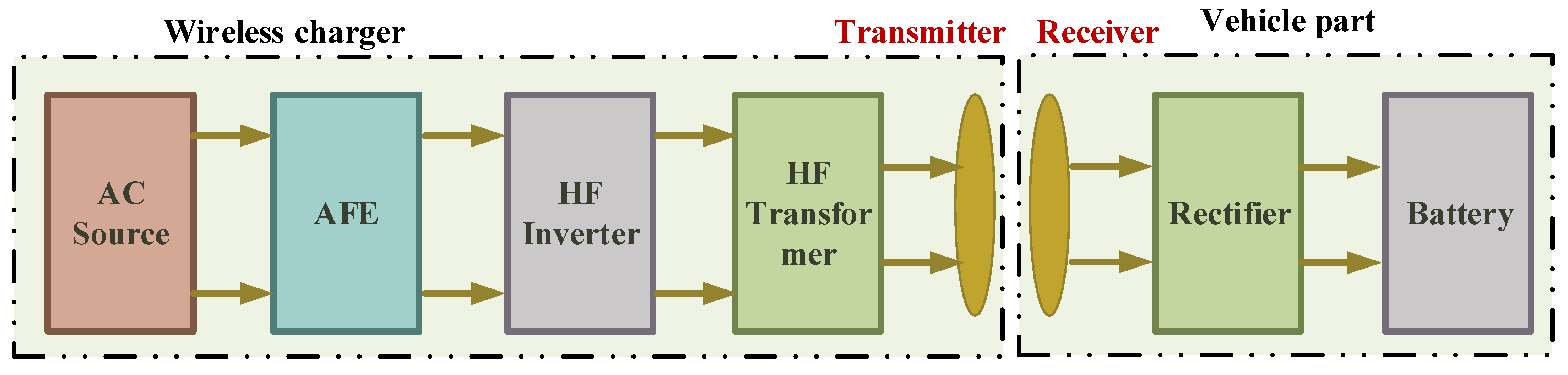
Figure 10.
Demonstration of wireless charging.

Figure 11.
Categories of foreign object detection and metal object detection.

Figure 12.
A wireless charging system and an FOD system.

Figure 13.
Quadruple Power Pad Coil.
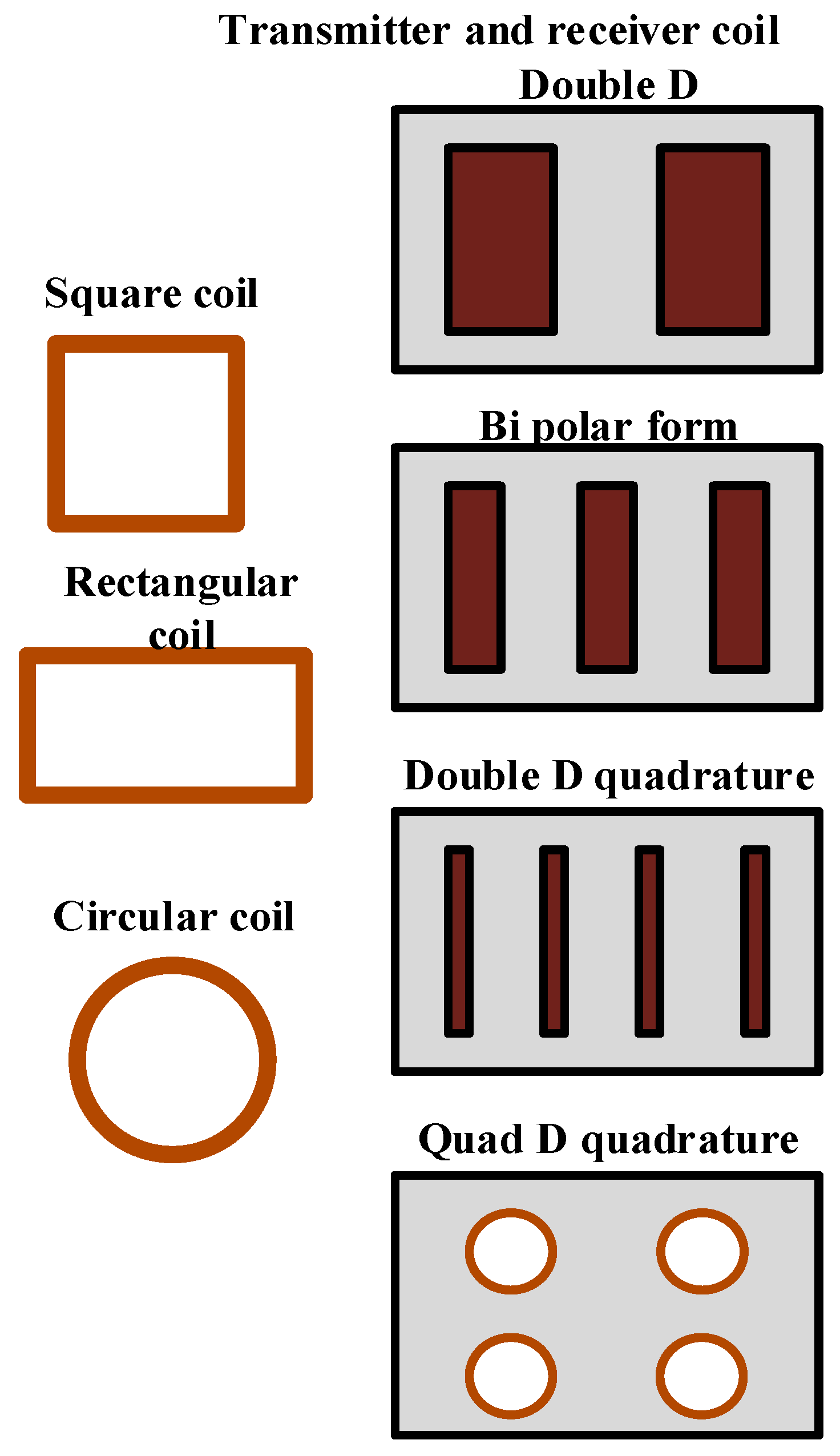
Figure 14.
Geometrical diagram of quadruple power pad structure.

Figure 15.
Composition of wireless transmitter system.
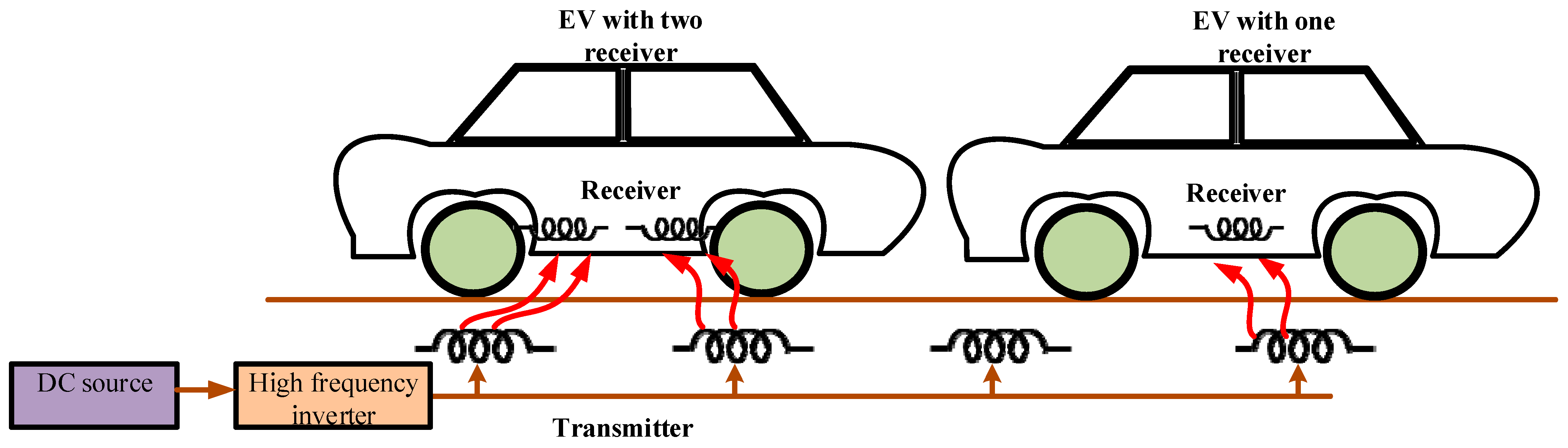
Figure 16.
Two instances of electric vehicles.
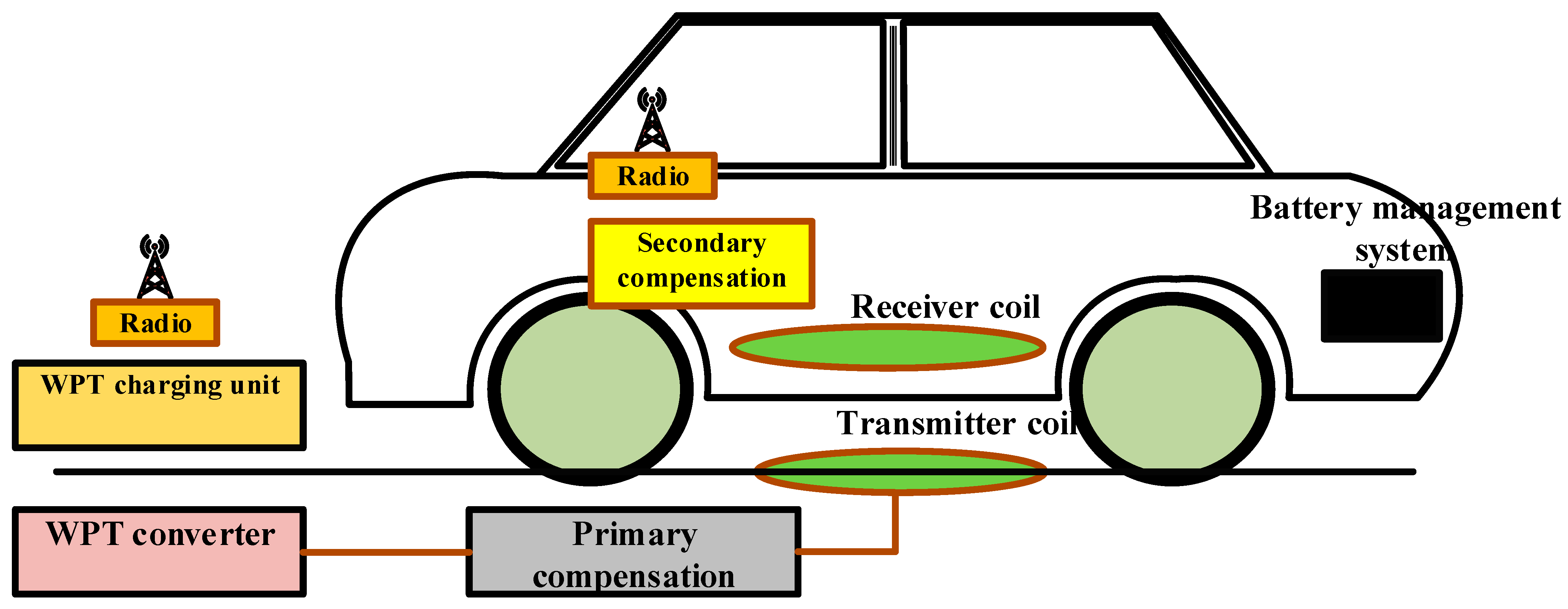
Figure 17.
Compensation topologies for primary and secondary resonant circuits.

Figure 18.
Exploded view of the power pad.
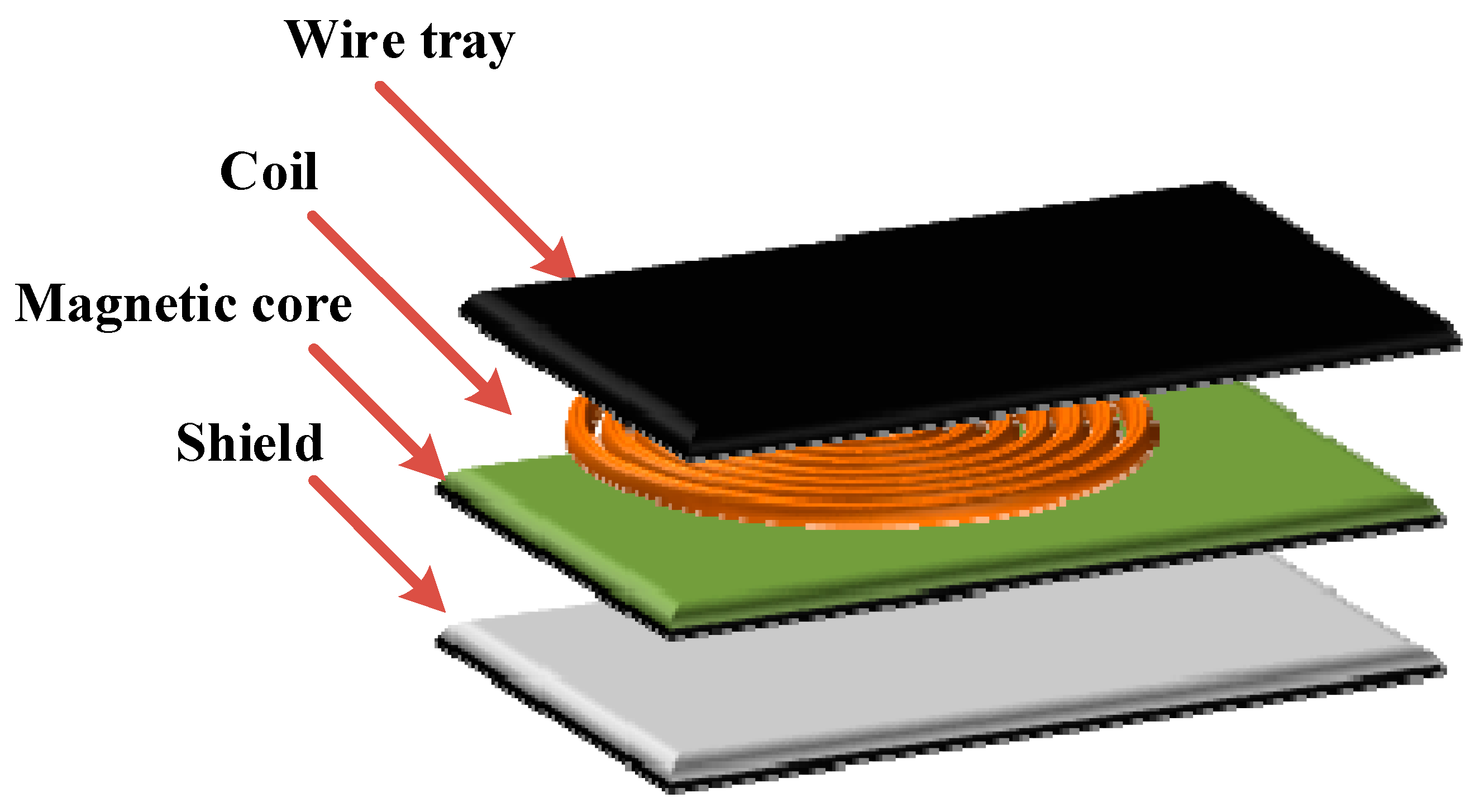

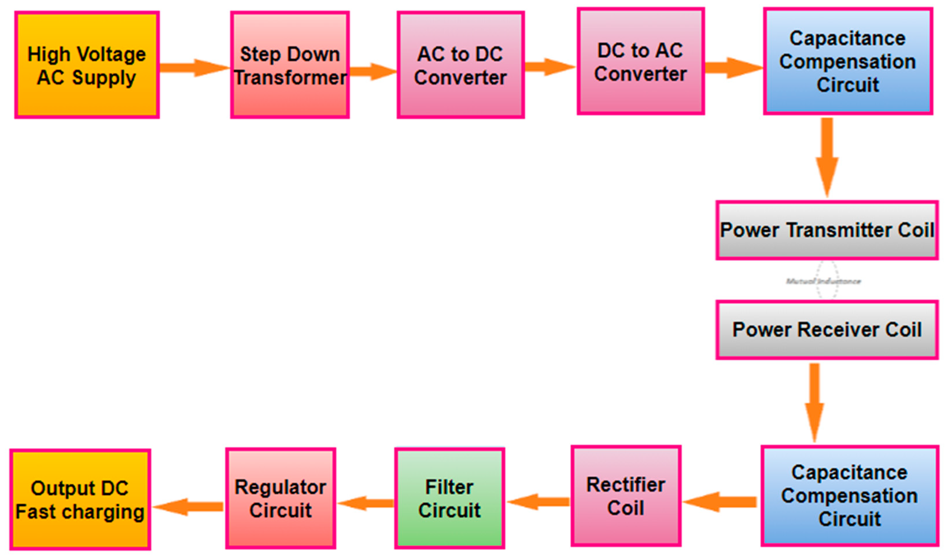
Table 1.
Various methods of WPT and their parameters.
| WPT Methods | The Distance between Transmitter and Receiver Circuits | Transmission of Power | Parameter Efficiency | Rate Cost | Safety and Protection |
|---|---|---|---|---|---|
| Inductive Coupling | Around a millimeter | A few watts or less | Minimum | It is economical to utilize secondhand equipment, since it is affordable and easily accessible. | It is secure from a biological perspective. |
| Capacitive Coupling | Multiple Kilowatts | A few Kilowatts or more | Minimum | It is less costly since the power transmission is done via aluminum plates. | Compared to the resonant approach, operation is safe. |
| Magnetic Resonance | A few meters | Kilowatts | Maximum | It is cost-effective, since old equipment is affordable and easily accessible. | It is secure from a biological perspective. |
| Microwaves | It can be produced up to 100 km. | Up to hundreds of Megawatts | Maximum | It is expensive compared to other treatments. | 1 GHz to 1000 GHz high-frequency radiation is unhealthy for human health. |
| Optical | Using a high-intensity beam, it may be utilized across greater distances than a few meters. | Up to hundreds of Megawatts | Minimum | It has identical financial circumstances to inductive coupling. | It would be detrimental to human health. |
Table 2.
Overview of earlier works on WPT.
| Problems Addressed | Performance Assessment | Key Contribution | Resolution |
|---|---|---|---|
| In an EV, using a cable circuit will harm the charger. Daily maintenance will be performed. The AC outlet requires plug-in. | Yokogawa digital power meter | Simple, cheap WPC prototype | The receiver coil attached to the battery picked up the magnetic induction created by the transmitter under the road. |
| Inductance coupling (efficiency improved). | Network reflection coefficient and scattering parameters | Employment of repeater concept | The power was doubled and reproduced in the air by the repeater coil, which was positioned between the transmitter and receiver. |
| Inhibited transmission efficiency and power loss transmission. | Unnamed optimization strategy | Phase shift amplitude control | While the active portion of the blockage was left alone on the receiving end, the sensitive portion of the obstruction had its impedance modified. |
Table 3.
WPT U.S. Technical specifications and safety requirements.
| Standard Developer | Standard Name | Published Year | Description |
|---|---|---|---|
| SAE | J2836/6_201305 | 2013 | Applications for PEV wireless charging communication |
| SAE | J2953/1_201310 | 2013 | Equipment for PEV compatibility with electric vehicles (EVSE) |
| SAE | J2953/2_201401 | 2014 | Procedures for testing PEV compatibility with EVSE |
| SAE | J2953/3 | 2016 | EVSE and PEV interoperability test scenarios |
| SAE | J2953/4 | 2020 | reporting on PEV charge rates |
| SAE | J2847/6 | 2020 | Wireless EV charging stations and light-duty PEVs can communicate for WPT. |
| SAE | J2954 | 2020 | WPT for plug-in light-duty vehicles, as well as alignment techniques |
Table 4.
Standardization of charging power levels for light-duty EVs.
| Classification | Power Level | Standard Status |
|---|---|---|
| WPT1 | 3.7 kW | SAE J2954 |
| WPT2 | 7.7 kW | SAE J2954 |
| WPT3 | 11 kW | SAE J2954 (WIP) |
| WPT4 | 22 kW | SAE J2954 (WIP) |
Table 5.
Worldwide technical standardization.
| Standards Inventor | Name of the Standard | Invention Year | Description |
|---|---|---|---|
| IEC | 61980-1-Ed.2.0 | 2020 | General Requirement, Part-I, EV-WPT system |
| IEC | 61980-3 | 2019 | WPT System-part-3 for electric vehicles: particular specifications for entire magnetic field WPT systems |
| IEC | 61980-2 | 2019 | Specific criteria for wireless communication systems among electric road vehicles (EVs) and infrastructure, outlined in part two of the electric vehicle WPT systems. |
| IEC | 61980-1:2015/COR1:2017 | 2017 | General Requirement, Part 1 of the EV-WPT system |
| IEC | 61980-1:2015/COR1 | 2017 | General Requirement, Part 1 of the EV-WPT system |
| IEC | 61980-Ed.1.0.New Addition | 2015 | General Requirement, Part 1 of the EV-WPT system |
| IEC | 61980/1 AMD 1 Ed.1.0 | 2015 | General Requirement, Part 1 of the EV-WPT system |
| IEC/TS | 61980-2 Ed.1.0 | 2017 | Widespread requirements for communication between electric-powered road cars and infrastructure concerning WPT devices and element 2 of EV-WPT systems |
| IEC/TS | 61980-3 Ed.1.0 | 2015 | Part 2 of the general necessities for the magnetic field power transmission gadget for EV-WPT systems |
| ISO | 19363:2020 | 2020 | Magnetic field WPT for electrically-driven road vehicles: protection and interoperability necessities |
| ISO | 9363:2017 | 2017 | Safety and interoperability criteria for electrically-driven road vehicles’ magnetic fields |
Table 6.
Challenges and issues faced by WEVCS.
| WPT Types | Resonant Coupling | Induction Coupling | Microwave |
|---|---|---|---|
| Difficulties | Moderate | Low | High |
| Distance capability | Maximum of 1 km | 5 mm | - |
| Efficiency performance | High | Low | High |
| Transmission of Loss | Moderate | High | Low |
| Number of receivers entering | Multiple receivers are applicable | Utilizing a single receiver is appropriate | Single receiver |
| Power wave | Fluctuating power signal | Continuous | Continuous |
| Radiation energy | Non-radiant power | Non-radiant power | Radiant power |
| Frequency range | Power transmitted at 6.7 MHz Control signals at 2.4 GHz | 110–205 KHz | 300 MHZ–300 GHz |
| Receiver | Coil of copper with few turns | Coil of copper with few turns | Rectenna with SCR |
| Safety considerations | Risk of sparks produced at several million volts | Considered harmless | Detrimental to living matter, like telecommunications |
| Transmission of energy | Electromagnetic resonance | EMI | Radiowave, microwave, and laser |
| Transmitter | Primary coil with a short gap and few turns. The secondary coil contained 10 times as many turns as the primary coil without a gap. | Several-turn copper coil | Antenna for transmission that uses a wave guide |
Table 7.
Advantages and disadvantages of FOD.
| Methods for Detecting Foreign Objects | Benefits | Drawbacks | Comments |
|---|---|---|---|
| Method for power; oss analysis | Detects while it is powered. | High-powered wireless charging is not recommended. Only metal detection is involved, not the transmitter or receiver. | Power consumption is low. |
| System parameter change detection method | No extra equipment and implementation is easy. | A small metal item is hard to find. Depending on the primary power source, only metal detection occurs. | Power consumption is low. |
| Image, thermal and radar sensing | Can identify living things and metal. | High price, failure-pronse, and has environmental factors. | Detects both metal and living things. |
| Magnetic field change detection method | High-power wireless charging is acceptable, regardless of the weather. | Low-power wireless charging is challenging; detection occurs while charging. | Relates to high-power wireless charging. |
| Laser sensor | Able to find any object, suitable for all wireless charging levels. Reliable and simple to implement. | Costly, but very simple and robust. | Proposed laser sensor-based system. |
Table 8.
Requirements for averting the basic compensations’ bifurcation occurrence.
| SS | SP | PS | PP | |
|---|---|---|---|---|
| Primary Capacitance | ||||
| Bifurcation |
Table 9.
Analysis of review study on resonant power transmission.
| Complication to be Resolved | Involvement in This Paper | Resolution | Performance |
|---|---|---|---|
| A single base station for power delivery and data collecting in WSN | Fully automated recharging of mobile vehicles. | The driving assistance (automotive vehicle) travels along defined routes according to the blueprint, and OPT-4 transfers electricity to the necessary nodes. | OPT-5 OPT-1 |
| Multi-frequency | Multi-frequency unwired power transmission system. | Certain electrically-powered equipment could only receive electricity from a predetermined frequency channel. | ----- |
| The transmitter circuit’s nearby and reserved loads each received the same amount of energy. | Technique for electrical circuit separation matching of impedance | Employment of several repeaters and resonators to create arithmetic derivations was suggested. | Power division method |
Table 10.
Overall impedance of compensation topologies.
| Symbol Representation | Equation |
|---|---|
Table 11.
Comparison table of the Network Topologies.
| Characteristics of Topology | SS-Type Topology | SP-Type Topology | PS-Type Topology | PP-Type Topology |
|---|---|---|---|---|
| The primary compensation capacitance found in the load condition, which a significant impact on topology. | - | - | Interdependent | Interdependent |
| The circuit equivalent impedance at resonance | Minimum | Minimum | Maximum | Maximum |
| The AC power supply type that will be utilized to transfer a large amount of power | Voltage power source | Voltage power source | Current generator or power source with very high voltage | Current generator or power source with very high voltage |
| At the stable current source (SS, SP), energy is transmitted (PS, PP) | Lower | Higher | Lower | Higher |
| Peak performance of efficiency | High | Low | High | Low |
| Power factor tolerance for changing frequency | Lower | Greater | Lower | Greater |
| The capability of power transmission | Maximum | Maximum | Minimum | Minimum |
| As a function of distance, power factor sensitivity | Minimum | Minimum | Medium | Medium |
| Alignment tolerances | Maximum | Maximum | Medium | Minimum |
| The impedance range at the resonance state | Minimum | Minimum | Maximum | Maximum |
| Suitability for use in electric vehicles (EV) | Maximum | Maximum | Medium | Medium |
Table 12.
Comparative evaluation of various coils’ design methodologies.
| Design Specification of Coils | Rate Range of Misalignment | Tolerance for the Flux Path’s Height |
|---|---|---|
| Circular type | Zero at 40–50% range in diameter. | ¼ amount of a coil’s diameter |
| Magnetic Flux pipe/flat solenoid | A great step toward tolerance. | ½ amount of a coil’s length |
| DD coil type | Null at 35% of the length of the pad (x-direction). | ½ the amount of the coil’s length |
| DDQ coil type | Around 96% of the length, null (x-direction). | 2 circular times |
| Bipolar coil type | Approximately 96% of the length was null (x-direction). | 2 circular times |
| Tripolar coil type | Non-symmetrical type of tolerance. | N/A |
| Zigzagcoil type | No null and empty values are present in this. | 1/(2.5) amount of the coil’s length |
Disclaimer/Publisher’s Note: The statements, opinions and data contained in all publications are solely those of the individual author(s) and contributor(s) and not of MDPI and/or the editor(s). MDPI and/or the editor(s) disclaim responsibility for any injury to people or property resulting from any ideas, methods, instructions or products referred to in the content. |
© 2023 by the authors. Licensee MDPI, Basel, Switzerland. This article is an open access article distributed under the terms and conditions of the Creative Commons Attribution (CC BY) license (https://creativecommons.org/licenses/by/4.0/).
Share and Cite
MDPI and ACS Style
Palani, G.; Sengamalai, U.; Vishnuram, P.; Nastasi, B. Challenges and Barriers of Wireless Charging Technologies for Electric Vehicles. Energies 2023, 16, 2138. https://doi.org/10.3390/en16052138
AMA Style
Palani G, Sengamalai U, Vishnuram P, Nastasi B. Challenges and Barriers of Wireless Charging Technologies for Electric Vehicles. Energies. 2023; 16(5):2138. https://doi.org/10.3390/en16052138
Chicago/Turabian StylePalani, Geetha, Usha Sengamalai, Pradeep Vishnuram, and Benedetto Nastasi. 2023. "Challenges and Barriers of Wireless Charging Technologies for Electric Vehicles" Energies 16, no. 5: 2138. https://doi.org/10.3390/en16052138
Note that from the first issue of 2016, this journal uses article numbers instead of page numbers. See further details here.