
Current Status and Development Direction of Low-Carbon Exploitation Technology for Heavy Oil
1
University of Chinese Academy of Sciences, Beijing 100048, China
2
Institute of Porous Flow & Fluid Mechanics, Chinese Academy of Sciences, Langfang 065007, China
3
PetroChina Research Institute of Petroleum Exploration and Development, Beijing 100083, China
*
Author to whom correspondence should be addressed.
Energies 2023, 16(5), 2219; https://doi.org/10.3390/en16052219
Submission received: 6 December 2022
/
Revised: 18 December 2022
/
Accepted: 23 December 2022
/
Published: 24 February 2023
(This article belongs to the Special Issue Advances of Heavy Oil Recovery Technologies with Low Carbon-Intensity)
Abstract
:With the strategic goal of “carbon peaking and carbon neutral” in China, new requirements are also put forward for the thermal recovery of heavy oil. In view of the problems of excessive greenhouse gas emission, low steam utilization rate, poor economic efficiency, and limited reservoir application of steam stimulation replacement technology in China, the emerging technologies of medium- and low-temperature thermal fluid, solvent-assisted high-temperature steam injection, solvent-based medium- and low-temperature waterless recovery and in situ electric heating-assisted recovery are discussed in terms of technical principles, technical parameters, experimental/field effects, and technical and economic potential. The technical principles, technical parameters, experimental/field results, and techno-economic potential of low-carbon heavy oil recovery technologies are summarized and future development directions and trends are anticipated. The study’s findings indicate that some of the technologies that have been tested in the field, such as HWVP, EMVAPEX, AH-VAPEX, LASER, and ESEIEH, can be developed by relying on the original well groups for production and can reduce greenhouse gas emissions, such as CO2, by about 80% and improve crude oil recovery by 5% to 10%, while the technologies concerned have outstanding effects on increasing oil production rate and lowering upfront capital investment. Some of the technologies that have been tested significantly increase oil production rate, lower initial capital expenditure, and enable solvent recycling, among other things. Among them, COBEEOR and N-SOLV technologies can also lower the amount of asphaltene in the output crude oil, enhance the API of the recovered crude oil, and provide strong economic advantages. CSP, CHSI, and hot water solvent injection were tested in indoor two-dimensional and three-dimensional experiments to validate their feasibility, while CO2, propane, and butane solvents were initially screened and some of the technologies’ mechanisms were revealed to lay the groundwork for pilot projects. The executive summary of the research findings will serve as a guide for future low-carbon extraction technology research and development in China.
1. Introduction
In China, heavy oil deposits make up a significant share of the proven crude oil reserves. However, there are many reservoir types, significant heterogeneity, complicated mineral components, and significant viscosity fluctuations, all of which have specific technological needs. The primary method of recovering heavy oil in China at the moment is thermal recovery, which produces more than 85% of the country’s yearly output. Thermal recovery techniques include steam stimulation, steam-aided gravity drainage, steam flooding, and in situ combustion. Currently, the world’s proven crude oil reserves are estimated to be between 1.4 and 2.0 × 10¹² t, of which heavy oil and asphalt reserves make up a significant portion—more than 60% [1]. The development of oilfields is crucial given China’s confirmed heavy oil reserves, which make up around 8% of the country’s total oil and gas reserves and are spread over Songliao, Bohai Bay, Junggar, Nanxiang, and other oil- and gas-producing basins. The chain-breaking and reforming technology can use the effect of positive carbon ions to break some of the long carbon chains in heavy oil to form short carbon chains at the reservoir temperature. As a result, the quality of the heavy oil after chain-breaking and reforming will improve, the viscosity will reduce, its mobility in the reservoir and wellbore will be increase, and the waxing will reduce. The kind, mass fraction, and response time of chain-breaking reformers, however, have not been well studied [2]. The development of heavy oil has been the main area of activity in the energy sector since the implementation of the 13th Five Year Plan. The geological reserves of heavy oil now being developed commercially in China are 14 × 108 t [3].
The two primary types of heavy oil reservoir development procedures are thermal recovery, which includes thermal fluid flooding and in situ combustion, and non-thermal recovery, which mostly includes chemical reagent viscosity reduction and dilution viscosity reduction methods. The primary method of recovering heavy oil nowadays is thermal recovery. The production of heavy oil globally is around 100 × 104 t/d, and the thermal recovery output surpasses 60%. In China, the entire output of heavy oil exceeds 2500 × 104 t, and the thermal recovery output also exceeds 1500 × 104 t. The steam injection recovery method currently dominates the thermal recovery technology field (including steam stimulation, steam flooding, and steam-assisted gravity drainage). In order to efficiently lower the viscosity of heavy oil and produce some displacement kinetic energy, this method is based on the fact that the heat produced by high-temperature steam is transported to the target layer by convection and conduction [4,5]. The development impact of heavy oil is improved by a higher steam injection dryness. The recovery factors of steam stimulation, steam drive, and steam-aided gravity drainage may all reach more than 50%. The recovery factors of steam huff and puff can often reach 20% to 30%. However, the production of steam unquestionably adds to the environmental load and produces a significant amount of greenhouse emissions. The thermal recovery technique for heavy oil has the following issues with China’s proposed “carbon peaking and carbon neutralization” strategy: ① Emissions of greenhouse gases. Heavy oil thermal recovery will likely result in significant greenhouse gas emissions, such as the 65.6 × 10⁸ m3 flue gas and 211 × 104 t CO2 emissions from Shengli Oilfield thermal recovery in 2020, which will add to the burden on the environment [6]. ② Low steam usage rates cause significant heat energy loss. The boiler, steam injection pipeline, and steam injection wellbore all lose heat to varying degrees during the steam thermal recovery process. Statistics show that the steam dryness at the steam injection furnace’s outlet is between 70 and 75%, while the steam dryness transmitted to the well’s bottom is only between 30 and 40% [7], which raises the cost of developing heavy oil steam huff and puff and has an impact on the economy of thermal recovery technology. ③ Lack of post steam stimulation replacement technology. The oil steam ratio is approaching the economic limit, and the development effect is bad as the rate of oil production of steam declines in the latter phase. However, there are several restrictions on how steam stimulation recovery replacement methods may be used, including steam flooding and in situ combustion. Although hot water flooding is low and this water easily flows into high-permeability channels during heavy oil hot water flooding, this leads to poor hot water sweep volume and sweep efficiency [8].
In recent years, a variety of innovative heavy oil exploitation technologies have been created and established in response to the aforementioned issues. Microbial enhanced oil recovery [9] employs subsurface microorganisms to create metabolites (such as acids, gases, biosurfactants, and so on) in order to reduce crude oil viscosity and modify the physical conditions of the reservoir, thereby enhancing recovery and production capacity. The method has received less attention in terms of microbial oil flooding mechanisms, dominant strain identification, and microbial community structure. The in situ normal-temperature chain-breaking and upgrading technology [10] can use the effect of positive carbon ions to break some of the long carbon chains in heavy oil to form short carbon chains at the reservoir temperature. As a result, the quality of the heavy oil after chain-breaking and reforming will improve, the viscosity will reduce, its mobility in the reservoir and wellbore will increase, and the waxing will reduce. The kind, mass fraction, and response time of chain-breaking reformers, however, have not been well studied. The development of medium- and low-temperature thermal fluids, solvents, and non-condensable gas to partially or completely replace steam for heavy oil exploitation, downhole electric heating heavy oil exploitation, in situ upgrading, and other technologies, in addition to traditional thermal recovery technology, can effectively solve some of the current problems of heavy oil exploitation, reduce the cost of heavy oil exploitation, and reduce greenhouse gas emissions. For example, Table 1 lists the CSS-based LASER, CHSI, and CSP technologies, which replace steam with steam + solvent or ambient (hot) solvent for stimulation; EMVAPEX, AH-VAPEX, and N-SOLV, which change the solvent injection temperature or injection timing based on ES-SAGD; and resistance heating-assisted CSS/SAGD, effective solvent recovery incorporating electromagnetic heating, HWVP, crude oil breaker electric enhanced oil recovery. Each of these technologies have achieved significant results in indoor studies or field pilots.
2. Medium- and Low-Temperature Fluid Exploitation Technology
2.1. Non-Condensate-Assisted Thermal Recovery
The use of pure steam for oil flooding is constrained by issues including rapid steam condensation and a constrained wave range, which substantially reduce its usefulness [11,12]. The mechanism of N2 supplementary steam flooding, including heat insulation, blocking, and energy boosting to aid discharge, has also been extensively explored [13]. According to Wang [14], the combined injection of N2 and steam might result in a more pronounced impact of improved heat transfer, and the rate at which isothermal steam is consumed decreases as the N2 level in the combined gas increases. Through one-dimensional studies, Li Zhaomin et al. [15] further confirmed that flue gas also boosts steam heat transfer and condensation inhibition. Non-condensable gas addition reduces the exothermic flow of steam at the front end of the reservoir, slows down the heat exchange rate between steam and rocks there, prevents the formation of liquid droplets when steam is cold, and prevents steam condensation. It also increases the resistance to heat transfer between steam and rock surface by converging liquid droplets produced after condensation and attaching them to the rock surface. The use of steam drive might result in significant heat loss for reservoirs with small reservoir thickness [16]. The hot water vapor process (HWVP) technology consists in injecting a non-condensable gas into a heavy oil formation together with water vapor for operation (a surface in-line heater produces low-temperature and low-pressure hot water vapor, which is then carried into the formation with NCG). The non-condensable gas transports water vapor, which is water in an unsaturated gaseous state, to the formation. Steam and water vapor carry the same amount of heat energy into the reservoir due to their chemical and thermodynamic consistency. As shown in Figure 1, thermal injection into CHOPS wells is estimated to have an operational limit of 140 °C and pressures between 500 and 3000 kPa; the only way to achieve this is to inject hot water. Yet, as was already indicated, hot water has a very low enthalpy and a weak development impact. By contrast, the HWVP uses a non-condensable gas to carry low-temperature and low-pressure water vapor injection, which can keep the water vapor in a gaseous state under the same temperature and pressure conditions, significantly expanding the range of heat transfer and supplying the formation energy due to the addition of non-condensable gas [17]. The experiment employed N2 for two injection cycles with an injection time of approximately one month, during which the reservoir pressure increased to almost the original pressure of 3.5 MPa, while the bottomhole temperature was only 130–140 °C. The technique was technically piloted by Husky [18]. The initial rate returned to the pre-shut-in level after injection of 500–600 e3m3 of N2 into a total of 85 m3 of cold water equivalent water vapor, but owing to production variables, the ensuing economic gains are not significant.
2.2. Hot Water and Solvent Injection
Studies on the alternating injection of steam and hydrocarbon solvents in fractured reservoirs to improve recovery have increased in recent years. The alternating hot water + solvent injection [16] can significantly increase recovery even with the injection of hot water at a relatively low temperature. This is in contrast to steam. This process is broken down into three steps. The first stage, called thermal conditioning, involves injecting hot water into the reservoir at a proper temperature to pre-heat crude oil. A little quantity of oil may be generated during this stage as a result of the crude oil’s expansion. The crude oil is subsequently extracted by hand lifting, etc., after a solvent such as isothermal n-heptane or distillate is pumped into the formation to dissolve it in the heavy oil and significantly lower its viscosity. In the third step, hot water is once more injected (the temperature is chosen based on the formation pressure and boiling point of the solvent), and the solvent that has not yet dissolved in the heavy oil system is evaporated in order to fulfill the solvent recovery goal. In a 10-group controlled study, Gökhan Coskuner et al. [19] varied the kind of injection solvent (heptane and distillate), cycle injection time and length, and other experimental factors for oil sands in the Sparky formation in the Dee Valley region. The oil sands in this region had an average water saturation of 20–25% and a viscosity of 14,000 mP·s at 20 °C. The experimental findings demonstrated that, using the method, asphaltene precipitation ranged from 2.5 weight% to 11.7 weight%, solvent recovery ranged from 45 to 55%, and ultimate recovery ranged from 42 to 88% OOIP. On the other hand, Haddad and Gates [20] discovered that using 25% CO2 + 75% hot water injection led to a recovery rate that was more than twice as high as pure CO2 after numerical simulation of hot water recirculation CO2 injection. The CO2-hot water process was also able to increase recovery by 2.4%.
3. Solvent-Assisted High-Temperature Vapor Injection Technology
3.1. Enhanced Modified Vapor Recovery and Azeotropic Heated Vapor Recovery
Butler et al. introduced solvent exploitation based on SAGD in 1991. This approach may successfully address issues such as fuel expense, CO2 emissions, etc. There are currently two major types of solvent addition: pure solvent injection and steam/solvent co-injection (up to 20 vol% of light hydrocarbon solvent for steam injection) [21,22]. A novel method called enhanced modified vapor recovery (EMVAPEX) efficiently addresses the issue of high solvent chamber rise resistance of solvent exploitation alone by substituting condensate gas (such as propane) for steam after the first operation of steam-aided gravity drainage (SAGD). SAGD is created for heat formation and to generate steam in the steam chamber before the average temperature of the target reservoir region exceeds the bitumen’s flowable range. As shown in Figure 2, the injection of pure solvent gas (for example, propane) or solvent + steam (within 10 vol%) is switched to solvent exploitation to enable subsequent hot solvent expansion of the chamber once the steam chamber has reached a certain level (when the bitumen recovery rate reaches about 20–30%). EMVAPEX is SAGD first, relying on the high heat capacity of steam to heat the formation and form a larger steam chamber upfront, and then injecting a thermal solvent to reduce crude oil viscosity [23], while using infill wells to further improve solvent exploitation efficiency. This differs from VAPEX, where the solvent is injected at the beginning. In 2016, the Christina Lake Regional Project used original SAGD wells for an EMVAPEX pilot by injecting propane, and one well group was used in Phase I of the project to initially verify the feasibility of the technology. The project pilot has now reached Phase III, during which time it will further identify variables including reservoir dynamics and recovery rates and build infrastructure for recovering propane. When steam oil ratio equals 3, EMVAPEX may produce crude oil at a rate that is 20% greater than SAGD, while recovering crude oil at a rate that is more than 75% higher (5–10%) and reducing greenhouse gas emissions by roughly 43%. The shift to EMVAPEX might start as early as 2023, and the technology will continue to be assessed going forward, for instance by comparing production outcomes with the removal of propane injection.
Azeotropic heated vapor recovery (AH-VAPEX) is a low-pressure recovery technique suitable for inhomogeneous reservoirs [24]. This method involves replacing the SAGD pure steam with a superheated mixture (80–170 °C) consisting of roughly 90% vol solvent + 10% vol steam and injecting it into the formation. The mixture creates a solvent chamber within the reservoir, which works to help with solvent gas expansion due to the addition of steam, which resolves the issue of high resistance to the rise of the solvent chamber of pure solvent exploitation. On the one hand, the use of steam helps the solvent chamber expand, resolving the issue of the solvent chamber’s strong resistance to increase in the case of pure solvent exploitation. However, due to the superheated state of the mixture, the solvent condenses at the asphalt–solvent interface. Additionally, the condensed state hydrocarbon compounds mix with the asphalt, resulting in the formation of a diluted asphalt mixture that is less viscous than the virgin asphalt and functions as a deasphalting agent. The initial fixed expenditure for an AH-VAPEX well can be cut in half while maintaining the same SAGD well construction and original SAGD well operation. Achieving conventional SAGD levels of crude oil production, recovery rates of over 70%, and solvent recovery of over 90% while using only 10% vapor in the injected mixture also results in thermal energy reductions of roughly 70% compared to conventional SAGD, 60% reductions in greenhouse gas emissions, and 90% reductions in water use per barrel. With pre-construction work starting in late 2019 and a field pilot scheduled to start in 2022, the AH-VAPEX field pilot [25] aims to improve the AH-VAPEX process and technology in a pilot area located in northeastern Alberta, Canada. The trial period will last for three years, with the injection pressure changing once a year to study recovery at three different injection pressures. The start date of the project has since been moved to 2023.
3.2. Liquid Addition to Steam for Enhancing Recovery
Circulating steam stimulation (CSS) is the process of injecting a quantity of steam into a well, shutting it off and smothering it for a period of time to induce the well to self-inject and then turn to recover oil. When the oil output reaches a particular point after the steam heat curing process, the well can resume oil recovery and perform the aforementioned procedure once more. The procedure employs injected heat to significantly enhance crude oil flow and create a dramatic decrease in crude oil viscosity. The crude oil also experiences thermal expansion at the same time, and when the volume factor rises, the residual oil saturation gradually reduces and the crude oil recovery improves [26,27].
Liquid addition to steam for enhancing recovery (LASER) is a technique that uses steam injected during the CSS process in place of steam + solvent (diluent such as C5) to increase steam stimulation. In Figure 3, well 2 is a combination of steam + solvent injection and well 1 is pure steam injection. The comparison demonstrates that, on the one hand, adding solvent can enlarge the steam chamber after it has condensed and flowed, and, on the other hand, the condensed solvent can be dissolved in the bitumen during formation, producing the effect of extracting and lowering viscosity [28]. With the use of 6% heptane as a solvent, this technique was tried as early as 2002 [28]. Indoor physical model testing revealed that the use of LASER greatly decreased the decline in oil stream ratio and boosted crude oil output by around 40%. According to the results of the field simulation, the asphalt yield increases after the LASER deployment appeared to stabilize at a level that was roughly constant and close to 50% of the OOIP. The OSR also increased from 0.2 to 0.3, and the final SSR (volume of solvent used per unit volume of asphalt increase) was around 0.2 (m3/m3). After 12 CSS cycles, LASER is expected to hasten healing by 6–7.5%, depending on when the therapy was started. Imperial Oil started a field pilot in Cold Lake [29], where C5+ diluent with a volume fraction of 6% was added to eight wells during the seventh CSS cycle. The field results showed that using this technology increases bitumen recovery and increases OSR by 33%, with 66% recovery of the injected diluent and partial recycling of the injected solvent.
Solvent addition not only decreases pressure during injection and increases flow ratio, but it also minimizes heat loss. When we compare the aforementioned solvent-assisted high-temperature injection technologies in Table 2, we can see that the target reservoirs for the pilot project are all low-temperature, low-pressure, shallow, super-thick reservoirs with high permeability and porosity, and crude oil viscosity changes significantly with temperature. For instance, when heated to 260 °C, Cold Lake field crude oil’s viscosity can be reduced to 5 mPa·s.
4. Medium- and Low-Temperature Waterless Exploitation Technology
In reservoirs with shallow burial and low formation energy, CSS and other conventional formation energy-based technologies are difficult to implement. It is simple for steam to break through the cover and escape from the ground when it is injected for use, which can result in severe production and safety catastrophes. In oil sand reservoirs with excessively shallow burial, SAGD horizontal well pairs might be challenging to drill. Second, large reservoir inhomogeneity is necessary for SAGD, and the steam chamber is undeveloped and unsuited for SAGD development for reservoirs with permeability contrast higher than 5 in the horizontal section. Conventional heavy oil development for ultra-shallow oil sand resources is challenging due to geological factors, the extraction process, and other factors, whereas solvent-based medium- and low-temperature anhydrous exploitation technology has advantages, such as low-temperature and low-pressure exploitation, strong reservoir adaptability, low energy consumption, and low environmental pollution.
4.1. N-SOLV
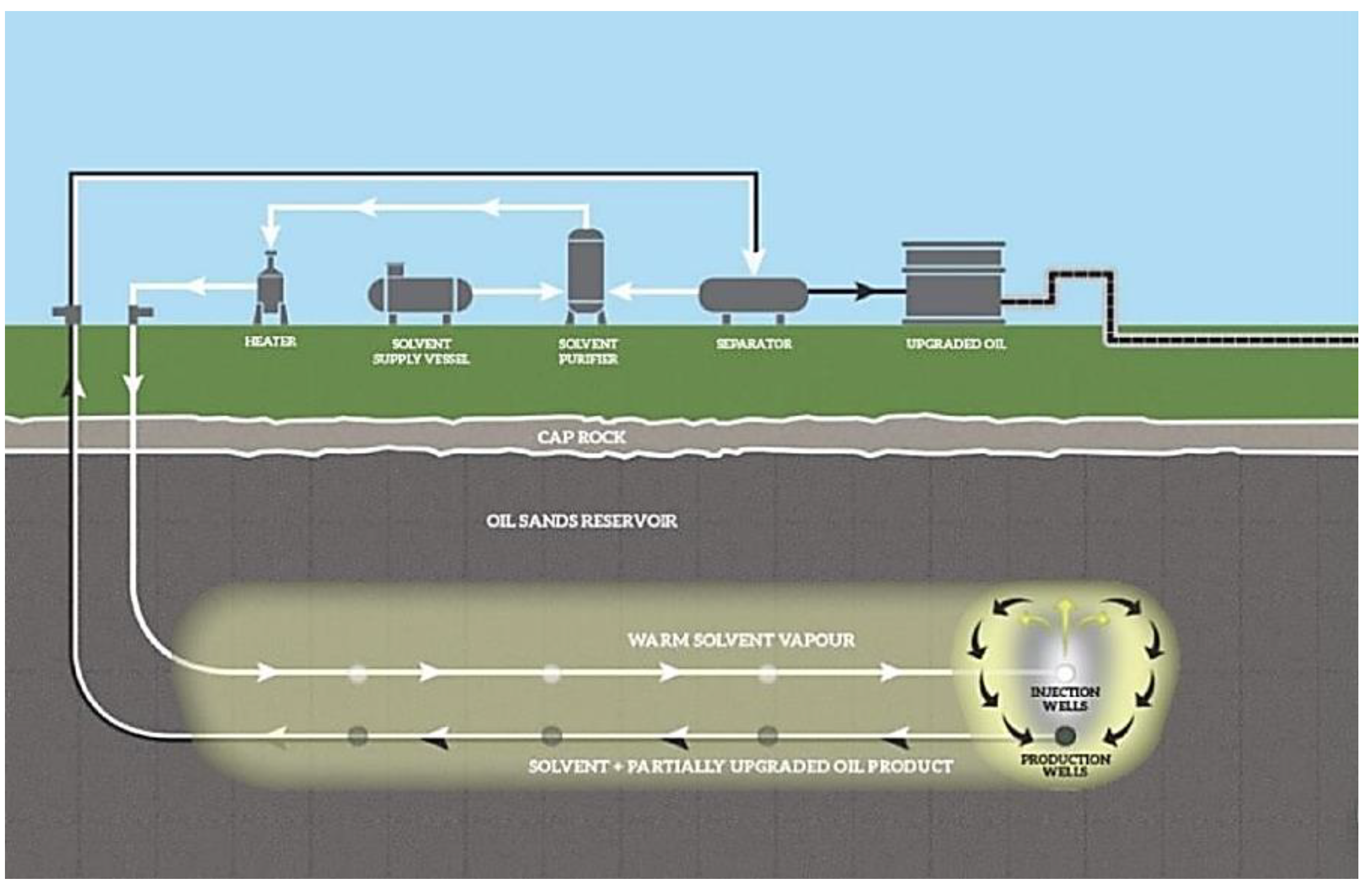
N-SOLV was developed by Emil and John Nenniger, who found that heating the solvent to vapor and adding a little amount of heat significantly boosts the solvent’s mixing with the asphalt, reducing viscosity and increasing production rate [30]. As indicated in Figure 4, this technique injects lower light hydrocarbons (propane, butane) at saturated vapor pressure into the reservoir and expands the solvent chamber with resistive heating to exploit heavy oil. The physical modification of thermal solvent breaks the planar stacking structure of gum and asphaltene molecules, causing them to become loose and thereby lowering heavy oil viscosity. As the solvent carries the heat produced by electric heating and reaches the oil layer to play a thermal viscosity reduction role, it also extracts the crude oil to precipitate asphaltene and residual oil in the reservoir, further reducing the viscosity of the recovered oil. By combining various viscosity reduction and extraction mechanisms, it improves the quality of the recovered crude oil [31,32].
Fang [32] performed an indoor two-dimensional experiment with 30% vol propane + 70% vol butane at 80 °C and 2 MPa, and the recovery rate was 72.1% and the solvent recovery rate was 85.1%. The results of an experiment by Zhang [34] using a visible three-dimensional physical model showed that the thermal solvent overlay has a significant impact and quickly dissolves oil, with final solvent recovery rates of 92% and oil recovery rates of 73%. In January 2014, the N-SOLV pilot test began with one well pair in the SUNCOR DOVER operation. A twin horizontal well resistance pre-heat start-up was employed to avoid heat absorption of hot solvent by steam condensate from decreasing solvent extraction output, and production terminated in March 2017, with a three-year total of 125,000 barrels of oil produced at a pace equivalent to that of SAGD. Recovery rate of crude oil was better than 65%, the solvent loss rate was less than 0.2 bbl/bbl, and the total CO2 emission reduction was greater than 80%. The API of crude oil was also enhanced to 13–14 (compared with SAGD). The technical advantages of N-SOLV are as follows: ① The solvent only has to be heated to 60–100 °C, requiring less thermal energy and reducing greenhouse gas emissions by 70–80%. ② No water is used throughout the process, which reduces the expenses of the surface boiler, heat injection pipeline, steam, and high-temperature output liquid treatment. ③ A simple and well-established method is the traditional SAGD wellbore process and surface hydrocarbon gas injection operation.
4.2. Cyclic Solvent Process
Similar to CSS, the cyclic solvent process (CSP) has three stages: injection, soaking, and production. The well is then sealed off to allow the solvent to diffuse and dissolve under high-pressure circumstances after it has been injected into the formation at the saturated vapor pressure associated with isothermal conditions. The well is opened as a production well for oil production activities after a period of shut-in during which the viscosity of the crude oil is lowered [35]. The production wells are again changed to injection wells after a cycle of oil production, and the procedure described above is repeated. This method is based on the three mechanisms’ synergistic enhanced oil—oil dissolution and viscosity reduction, foamy oil flow, and solution gas drive [36]—while the accessible solvents include CO2, methane, ethane, propane, butane, and their two-component gases in two combinations. In the Cold Lake field, Imperial Oil tested the CSP for propane injection using three horizontal wells and six monitoring wells in 2014. According to the findings, CSP decreases carbon emissions by 90% compared to CSS and boosts recovery rates from 30% to 40% to 50% to 60%. G The pilot CSP projects for methane-propane, propane-CO2, and pure CO2 were summarized by Okhan Coskuner et al. [37], and the results showed technical success using all these solvents, with 65% recovery of pure CO2 and 37% CO2 retained in the formation; methane-propane mixed solvent injection achieved 50% oil recovery, but nearly 50% loss of solvent; and propane-CO2 achieved 60% to 65% oil recovery. In an indoor test, Ivory et al. [36] used a 28% propane + 72% CO2 solvent and got the recovery of more than 40% after six cycles (initial recovery was less than 7%).
4.3. Cyclic Hot Solvent Injection
Hot solvent recirculation injection (CHSI) entails injecting a hot solvent into the formation at a specific pressure and temperature, stopping the well for a while to allow the solvent to mix with the crude oil, pumping the diluted oil and the injected solvent to the surface, and then beginning a new cycle from the injection stage [34]. In the event that solvent condensation occurs during the injection procedure, hot solvent is injected at a temperature level that is just marginally higher than the solvent’s dew point temperature. Thus, the mechanism of CHSI is similar to CSI, mainly including oil dissolution and viscosity reduction, foamy oil flow, and solution gas drive [31]. Before production begins, the solvent dissolves the crude oil and decreases its viscosity, which also improves mass transfer to some extent because of the solvent’s intrinsic heat. A small amount of solution gas gradually disperses on the oil surface when the production well pressure decays at a certain rate during production, creating a dispersed gas phase in both the oil and gas phases that is known as the foamy oil flow phase. As the pressure decreases significantly, the oil and gas system pressure become lower than the bubble point pressure, and the foamy oil flow vanishes, leaving a large amount of solution gas on the oil surface, which drives the diluted oil to move to the production well. Using oil samples from the Manatokan oil field, Kewei Zhang et al. [38] carried out a control experiment comparing CHSI with CSP. Propane was pumped into a 40 cm long, 20 cm wide, and 2 cm high experimental model at a temperature and pressure of 55 °C and 1.86 MPa, respectively. The test result indicated that the CHSI recovery rate was greater than 70% and that the oil production was maintained mostly without major hiccups. The comparison of CHSI technology’s involvement in reduced heat transfer viscosity and improved mass transfer is further supported by the comparison with CSP test results. As shown in Table 3, the indoor experiments of N-SOLV, CHSI and CSP are summarized.
5. Heavy Oil Electric Heating Development Technology
5.1. Effective Solvent Recovery Incorporating Electromagnetic Heating
Effective solvent recovery incorporating electromagnetic heating (ESEIEH) [40,41] is a VAPEX-derived technique that heats the formation and combinates solvents such as propane and butane to exploit heavy oil. The top injection well of this method contains electromagnetic wave transmitters situated in the horizontal part of the wellbore, which utilizes high-frequency electromagnetic waves to heat the formation to a temperature range of 40–70 °C and then inject hydrocarbon solvents. Under the effect of electromagnetic heating, the temperature of the formation in the near-well zone and between injection and production wells can be maintained in the above-mentioned temperature range, thereby accelerating the rate of solvent extraction and oil release and achieving efficient oil recovery. The typical resistance heating method has uneven heating, a heating range of just 1 m in the wellbore and near-well zone, and slow heat transfer and warming. The key to this technology is to use dipole aerials for electromagnetic radio frequency heating, which can penetrate oil layers up to 5 m away, and the penetration ability is positively related to the wavelength—the longer the wavelength, the greater the penetration ability—and finally achieve uniform heating of large volumes of oil reservoirs. In 2012, Suncor conducted the first pilot of in situ heating in the Dover reservoir (a three-phase project) to determine the electromagnetic wave power and formation electromagnetic wave absorption rates that penetrate the formation. During the 34-day heating operation, the technology heated the formation at a maximum sustained radio frequency power of 49 kW, averaged 26 kW during active heating, and had a maximum formation temperature of 127 °C, which is more in line with subsequent operating conditions. The project is currently in its second phase, with tests in a lateral horizontal section 150 m deep and 100 m long, to further explore the technology and calculate the cost and solvent usage. According to preliminary findings, the technology is water-free, does not require surface heat injection or subsequent high-temperature fluid production treatment, and produces roughly the same amount of oil as SAGD, while using less thermal energy (by 75%) and emitting 80% fewer greenhouse gases (by 80%).
5.2. Electrically Heated Assisted CSS/SAGD
High energy consumption, inconsistent horizontal well preheating, and restricted steam chamber development can all be associated with the SAGD process. The steam enthalpy can be raised, the near-well zone temperature can be raised, the resistance to wellbore flow can be decreased, and the SAGD impact may be improved with the help of the ohmic heating produced by resistance heaters. Currently, downhole resistance heating is mostly utilized to increase the amount of horizontal section activation and steam chamber development during the SAGD production phase and to pre-heat start-up of dual horizontal SAGD wells. Xi et al. [42] investigated the preheating stage of a dual horizontal well using numerical simulation with a real block in the Fengcheng heavy oil reservoir in Xinjiang. The findings demonstrated that efficient electrical heating could warm 90% of the horizontal well interval, shorten the time required for SAGD preheating from 220 days to 90 days, and lower the cost to $220,000. Through physical model experiments, Wang Chao [43] discovered that SAGD preheating with electrical heating assistance can achieve uniform preheating in injection and production wells in heterogeneous ultra-heavy oil reservoirs. The total electrical resistance heating power used in the experiments was 2.698 kW, and the well temperature could reach 300 °C. Wu Yongbin et al. [44] suggested installing electrical resistance heaters at fixed points in the wellbore of injection/production wells in low-permeability and interlayer sections to heat this section in formation in order to address the issue of the slow development of SAGD steam chambers in low-permeability reservoirs. The key mechanisms of electric heating-assisted SAGD in terms of drainage channel selection, steam chamber development, improvement of bottomhole steam dryness, and steam saving were revealed using a numerical modeling approach, demonstrating the enormous potential of electric heating-assisted SAGD applications.
In order to accomplish the lifting effect with electrically heated CSS, the traditional approach is to lower the cable or heating element to heat the wellbore over the paraffin precipitation temperature [45]. Ilyushin [46] depicts the pulsed heating process with the addition of heating elements, derives a mathematical model of the temperature field during pulsed heating, and creates a synthesis of pulsed control of the temperature field using Green’s function to determine the ideal number of heating elements needed to maintain a specific temperature state. However, this electric heating assistance method of combing paraffin deposits on the walls of the tubing does not provide significant improvement in horizontal well sections. To increase the mobilization rate and stimulation recovery rate of the horizontal portion of a horizontal well, Wu Yongbin et al. [47] suggested installing a high-powered electric resistance heater in the wellbore of the horizontal section. They derived and established the reservoir warming model of electric heating in collaboration with steam stimulation. In addition, this model was used in conjunction with indoor experiments and numerical simulations to uncover the primary mechanism of electric heating, which increases reservoir temperature in the vicinity of the well, lowers flow resistance into the well, enhances wellbore mobility, and produces uniform heating in the horizontal section. The method for electric heating-assisted horizontal well stimulation was optimized by Lü Berlin et al. [48] using reservoir numerical simulation. They also performed multi-factor calculations of the reservoir’s geological limits and key steam injection mechanisms, as well as optimized the well tubular column structure for electric heating and predicted the effect with a typical well group. The results reveal that after switching to electric heating, the OSR increased by about 0.08, the stimulation recovery rate climbed by 8.1%, and the degree of horizontal section activation increased from 73 to 89%.
5.3. Crude Oil Breaker Electric Enhanced Oil Recovery
Using electro-osmosis and electrochemistry, crude oil breaker electric enhanced oil recovery (COBEEOR) is a new-generation technology that effectively addresses the issues of low thermal efficiency, formation damage, and wellbore fouling during steam injection in karst cave/fractured carbonate reservoirs. This technique [49] entails installing the EEOR control panel electrical signal generator (located in a special container next to the cathode well), then connecting the generator to the casing or tubing and turning on the current; relying on the conductivity of the colloid structure of the soil particles, electrons on the microscale cross the electrochemical interface, and redox reactions occur at this interface. As a result of electrolysis, water produces hydrogen and hydroxide ions, whereas heavy crude oil undergoes electrochemical reductions to produce lighter liquid components, and then light oil is propelled toward the cathode well. Using this method, oil output from cathode wells may often be increased substantially, although anode well production will normally remain constant or slightly rise while producing crude oil with a high API, low viscosity, and sulfur content. The technology was piloted at Visoka oil field for 6 months in 2017. Cathode G-6 and anode G-86 were chosen as the two wells for the project. EEOR control panels and electrical signal generator were built between the two wells, and the wells were then put into production. A comparison of the crude oil produced from well G-6 with the control well G-625 in terms of crude oil viscosity, chemical composition, and API revealed that the well G-6 produced significantly less asphaltene and had an API of 9.4, while its production of crude oil increased from 252 to 1891 bbl/d and its water content dropped from 84 to 47%.
6. Discussion
In order for the low-carbon heavy oil extraction technologies to become the next generation of heavy oil extraction and address the production issues of “high energy consumption and high steam oil ratio” currently faced by the development of heavy oil reservoirs, it is necessary to find ways to encourage the industrialization of its application scale.
- (1)
- COBEEOR has been successfully flown, and no more research has been done to describe its mechanism. The non-condensate gas-assisted heavy oil thermal recovery technology has mostly matured, and its mechanism is understandable. In the following stage, multiple thermal fluids flooding to heavy oil recovery, more mechanistic research may be conducted.
- (2)
- Although EMVAPEX, AH-VAPEX, and LASER technologies have been sequentially piloted, there is still a dearth of studies in these fields despite their simplicity in theory: ① research on the correct timing of conventional SGAD to EMVAPEX and conventional CSS to LASER; ② selection of the finest solvent and the best ratio of steam to solvent injection; ③ experimental and modeling research describing the physics of solvent displacement at the pore layer; ④ investigation of how vapor aids solvent cavity growth, as well as the interplay between solvent cavity energy and mass balance. Even with single-component solvent injection, the interplay of energy and mass balance near the solvent chamber’s edge are not clearly defined.
- (3)
- For CSP and CHSI, ① the description of the solvent mass transfer process is insufficient. Previous studies have only looked at the diffusion coefficient of a single-component solvent in a heavy oil system, and there has not been much study on the diffusion coefficient of multi-component solvent diffusion at the same time; ② there is requirement to identify the driving mechanisms of foamy oil flow and solution gas drive in porous media. What is the dissolving pressure when several solvents are introduced simultaneously, and what is the sequence in which multiple solvents are released when the rate of pressure decay is unclear; ③comparable physical simulation standards are absent. However, current multi-scale physical and numerical simulation models do not incorporate field data to establish scaling guidelines for solvent injection rate or pressure, production pressure drop rate, time, production rate and recovery rate, etc. Similar physical simulation standards are a crucial tool for translating laboratory results to field applications; ④ hot solvent preparation is a significant issue in field applications due to the demand for thermal energy and the high cost of the solvent itself. Solvent recovery and the heat loss of the hot solvent in the wellbore need to be studied in greater detail.
- (4)
- The primary driving forces behind N-SOLV are heat transfer from solvent condensation and gravity drainage. However, due to the lengthy solvent soaking and oil production times, oil yield rates are poor. To find out if there are other driving forces and how to integrate them with solvent driving mechanisms to increase oil production rates, more experimental testing combined with indoor research is required.Pilot projects are scarce, and it is unclear which reservoir types the technologies are intended to target. The benefits and drawbacks of steam flooding, CSS, SGAD, in situ combustion, and other significant heavy oil recovery methods have been outlined, and the relevant conditions for each technology have been extensively compiled. However, due to the limited number of pilot projects, it is impossible to correctly sum up the reservoir conditions and technical factors for each of the new technologies that have been tested, such as injection temperature, injection solvent type, and injection complex composition. Although the indoor experiment shows that CHSI, hot water and solvent injection, and other technologies have high application prospects, microscopic technology research is still required to achieve the distance technology pilot. Numerous construction-related issues exist concurrently. A number of engineering issues exist concurrently. For instance, the use of electric heating technology more than the best power utilization will lead to the evaporation of formation water. The need to adjust the power in accordance with the actual reservoir conditions and production performance in a timely manner, while also taking into account the cost of electricity and other issues, will increase the difficulty of site construction.
7. Conclusions
- (1)
- CSS may be replaced in the future by CSP, CHSI, LASER, and electric heating-assisted CSS as a new technique for pre- and mid-term extraction of heavy oil reservoirs. Theoretically, CSP, LASER, and CHSI can be used as solvents in place of steam to increase crude oil viscosity, flowability, and deasphalting. Compared to CSS, the aforementioned technologies may successfully prolong the stimulation cycle and enhance CSS’s latter stages of development in terms of oil production rate, oil steam ratio, and anticipated ultimate recovery rate. The CSP pilot demonstrated an improvement in stimulation recovery from 30% to 40% to 50% to 60%; the LASER pilot demonstrated a 6–7.5% improvement in stimulation recovery and a 33% improvement in OSR; the electric heating-assisted CSS indoor test demonstrated an improvement in stimulation recovery of 8.1% and a 0.08 increase in OSR; and the CHSI indoor test also demonstrated a final recovery of more than 70%.
- (2)
- The technologies EMVAPEX, AH-VAPEX, ESEIEH, and N-SOLV are cost-effective and efficient and may be used as efficient replacements for medium- to late-stage heavy oil exploitation. The advantages of steam and solvent are combined in the partial replacement steam technique, which uses steam to aid solvent chamber expansion and speed up crude oil extraction using a solvent. AH-VAPEX oil produces at SAGD levels, with recovery ratio above 70%, reduces heat use by about 70%, and reduces greenhouse gas emissions by 60% per barrel. N-SOLV oil produces at a rate comparable to that of SAGD, with API increased to 13–14, recovery ratio above 65%, and CO2 emission reductions greater than 80% (compared to SAGD). In comparison to SAGD, EMVAPEX produces crude oil at a rate that is 20% higher, with a recovery ratio that is over 75% (5–10%) higher, and may cut greenhouse gas emissions by roughly 43%. ESEIEH has a higher oil output level compared to SAGD, recovery ratio of above 60%, but it reduces heat usage by 75% and greenhouse gas emissions by 80%. Indoor experiments and pilot test studies at the mine site have produced positive results. ESEIEH has a higher oil output level compared to SAGD, recovery ratio of above 60%, but it reduces heat usage by 75% and greenhouse gas emissions by 80%. Indoor experiments and pilot test studies at the mine site have produced positive results.
- (3)
- In situ heavy oil upgrading is achieved by COBEEOR using electrochemical principles. According to the findings of the pilot technology, the API improved to 9.4, the G-6 well’s crude oil output increased from 252 bbl/d to 1891 bbl/d, and the water content decreased from 84 to 47%. On the other hand, outcomes from HWVP and hot water and solvent injection are inconsistent since there has not been enough in-depth study on the mechanism, which is not of primary significance.
By replacing some or all of the steam, the heavy oil exploitation technique with low carbon emissions may significantly lower greenhouse gas emissions. The decrease in greenhouse gas emissions also lowers development costs, which results in increased economic advantages for the exploitation of heavy oil under the system of rigorous allocation of carbon emission objectives. It is easy to determine that the aforementioned technologies, whether they are field pilot or indoor experimental research, are aimed towards foreign heavy oil deposits. The geological conditions of Chinese reservoirs are very different from those of foreign reservoirs, and there are many problems such as strong inhomogeneity, many flow barriers, and large burial depth. The development of low-carbon technologies applicable to the development of China’s heavy oil reservoirs must be based on the principles of related technologies and combined with the unique characteristics of China’s reservoirs. As a result, it is not possible to simply learn from the experience of related foreign technologies.
Funding
This research was funded by the Science and Technology Project of CNPC (2021DJ3208, 2022KT0803 and 2021DJ1403).
Institutional Review Board Statement
Not applicable.
Informed Consent Statement
Not applicable.
Data Availability Statement
No new data were created in this paper.
Conflicts of Interest
The authors declare no conflict of interest.
References
- Yu, L. The distribution of world heavy oil reserves and its recovery technologies and future. Spec. Oil Gas Reserv. 2001, 8, 98–103. [Google Scholar]
- Zhang, Q. Potential and distribution characteristics of onshore heavy oil resources in China. China Sci. Technol. Inf. 2007, 2, 49–76. [Google Scholar]
- Jiang, Q.; You, H.J.; Pan, J.J.; Wang, Z.Y.; Gai, P.Y.; Lan, G.; Liu, J.L. Preliminary Discussionon Current Status and Development Direction of Heavy Oil Recovery Technologies. Spec. Oil Gas Reserv. 2020, 27, 30–39. [Google Scholar]
- Wu, T.T.; Geng, Z.G.; Du, C.X.; Li, B.; Gao, Z.N. Study on optimization of injection medium for thermal recovery of heavy oil in Bohai oilfield. Petrochem. Ind. Appl. 2019, 38, 25–30. [Google Scholar]
- Han, B.B. Study on Heat Transfer and Enhance Heavy Oil Recovery of Wellbore with Multiple thermal Fluids Injection. Ph.D. Thesis, Degree-Granting University, Heifei, China, 2018. [Google Scholar]
- Yang, Y. New progress and next development directions of heavy oil development technologies in ShengLi Oilfield. Pet. Geol. Recovery Effic. 2021, 28, 4407–4414. [Google Scholar]
- Wang, J.; Zhao, J.Q.; Pu, P.; Guo, W.Z.; Li, Y.J.; Liu, Y.P.; Mao, J. Processof heavy oilthermal recovery wastewater reused as power plant boiler make-up water. Chem. Ind. Eng. Prog. 2015, 34, 1–11. [Google Scholar]
- Wang, Y.Y.; Ren, S.R.; Zhang, L.; Peng, X.Y.; Pei, S.F.; Cui, G.D.; Liu, Y.M. Numerical study of air assisted cyclic steam stimulation process for heavy oil reservoirs: Recovery performance and energy efficiency analysis. Fuel 2017, 211, 471–483. [Google Scholar] [CrossRef]
- Zhang, J.H.; Guo, H.; Xue, Q.H. Potential applications ofmicrobial enhanced oil recoverytoheavy oil. Crit. Rev. Biotechnol. 2020, 40, 459–474. [Google Scholar] [CrossRef] [PubMed]
- Sun, N.W.; Li, J.H.; Wei, Q.W.; Wang, M.; Cao, C.J.; Mao, M.C. Upgrading technique ofthein-situ normal-temperature chain breakingfor enhancing theheavy-oildevelopment effect. Pet. Geol. Oilfield Dev. Daqing 2021, 40, 90–95. [Google Scholar]
- Ouyang, B.; Chen, S.B.; Liu, D.J. Appliance of nitrogen gas insulating heat and aiding flow technology in LiaoHe heavy oilfield development. Oil Drill. Prod. Technol. 2003, 25, 1–3. [Google Scholar]
- Fu, S.L.; Zhang, Y.H.; Liu, R.M.; Zheng, Z.M. Research progress of thermal recovery technology in heavy oil and super heavy oil reservoir. Energy Chem. Ind. 2020, 41, 26–31. [Google Scholar]
- Gu, H.; Cheng, L.S.; Zhang, X.L.; Zhao, Y.Q.; Peng, P. Research on Recognition of Ground-based Cloud Images Based on Multi-texture Features and PCA. Sci. Energy Eng. 2013, 32, 9494–9497. [Google Scholar]
- Wang, Y.P. Heat Transfer Enhancement Mechanism and Genesis of Nitrogen Assisted Steam Flooding. Spec. Oil Gas Reserv. 2018, 25, 134–137. [Google Scholar]
- Li, Z.M.; Xu, Y.J.; Lu, T.; Yang, J.P.; Wang, H.Y. Heat Transfer Enhancing Mechanism of Deep Steam with Non-Condensate Gas. Spec. Oil Gas Reserv. 2020, 27, 113–117. [Google Scholar]
- Coskuner, G. Enhanced Oil Recovery Potential of Lloydminster Heavy Oil Reservoirs. In Proceedings of the 23rd Annual Williston Basin Conference, Regina, SK, Canada, 28–30 March 2015. [Google Scholar]
- SPRI (Saskatchewan Petroleum Research Incentive). Horizontal Well Hot Oil Treatment(HOWHOT); Final Technical Report; Husky: Calgary, AB, Canada, 12 July 2016. [Google Scholar]
- Coskuner, G.; Huang, H. Enhanced Oil Recovery in Post-CHOPS Cold Heavy Oil Production with Sand Heavy Oil Reservoirs of Alberta and Saskatchewan Part 1: Field Piloting of Mild Heating Technologies. In Proceedings of the SPE Canada Heavy Oil Conference, Calgary, AB, Canada, 15–16 September 2020. [Google Scholar]
- Coskuner, G.; Naderi, K.; Babadagli, T. An enhanced oil recovery technology as a follow up to cold heavy oil production with sand. J. Pet. Sci. Eng. 2015, 133, 475–482. [Google Scholar] [CrossRef]
- Haddad, A.S.; Gates, I. CO2-based heavy oil recovery processes for post-CHOPS reservoirs. J. CO2 Util. 2017, 19, 238–246. [Google Scholar] [CrossRef] [Green Version]
- Upreti, S.R.; Lohi, A.; Kapadia, R.A. Vapor Recovery of Heavy Oil and Bitumen: A Review. Energy Fuels 2007, 21, 1562–1574. [Google Scholar] [CrossRef]
- Fayazi, A.; Kantzas, A. A review on steam-solvent processes for enhanced heavy oil/bitumen recovery. Rev. Chem. Eng. 2018, 35, 393–419. [Google Scholar] [CrossRef]
- eMVAPEX—MEG Energy. Available online: https://www.megenergy.com/operations/technology/emvapex/ (accessed on 9 September 2020).
- Xu, L.N.; Abedini, A.; Qi, Z.B.; Kim, M.; Guerrero, A.; Sinton, D. Pore-scale analysis of steam-solvent co-injection: Azeotropic temperature, dilution and asphaltene deposition. Fuel 2018, 220, 151–158. [Google Scholar] [CrossRef]
- Liu, Z.; Khaledi, R.; Farshidi, S.F.; Wattenbarger, W. A New Criterion for the Estimate of Impact of Lean Zones on the Performance of SAGD/SA-SAGD/EBRT Processes. In Proceedings of the SPE Canada Heavy Oil Conference, Calgary, AB, Canada, 15–16 September 2020. [Google Scholar]
- Peng, S.L.; Yuan, A.W.; Jiang, H.; Zhang, S. Cyclic preheating test in SAGD horizontal wells of Liaohe Oilfield. In Proceedings of the International Oil and Gas Conference and Exhibition in China, SPE 130948, Beijing, China, 8–10 June 2010. [Google Scholar]
- Gu, H.; Sun, J.F.; Qin, X.J.; Dong, C.; Li, H.Y. Potential evaluation of different thermal recovery technologies for heavy oil. Pet. Geol. Recovery Effic. 2018, 25, 112–116. [Google Scholar]
- Leaute, R.P. Liquid Addition to Steam for Enhancing Recovery (LASER) of Bitumen with CSS: Evolution of Technology from Research Concept to a Field Pilot at Cold Lake. In Proceedings of the SPE International Thermal Operations and Heavy Oil Symposium and International Horizontal Well Technology Conference, Calgary, AB, Canada, 4–7 November 2002. [Google Scholar]
- Leaute, R.P.; Carey, B.S. Liquid Addition to Steam for Enhancing Recovery (LASER) of Bitumen with CSS: Results from the First Pilot Cycle. J. Can. Pet. Technol. 2007, 46, 22–30. [Google Scholar] [CrossRef]
- Nenniger, J.; Nenniger, E. Method and Apparatus for Stimulating Heavy Oil Production: CA, US6883607 B2. 29 April 2008.
- Zhang, K.W.; Zhou, X.; Peng, X.L.; Zheng, F.H. A comparison study between N-Solv method and cyclic hot solvent injection (CHSI) method. J. Pet. Sci. Eng. 2019, 173, 258–268. [Google Scholar] [CrossRef]
- Fang, Y.Y. Optimization of the Thermal Solvent Recovery Formulation of Ultrashallow Oil Sands. Master’s Thesis, China University of Petroleum (Beijing), Beijing China, 2018. [Google Scholar]
- SDTC Awards Nsolv $13M to Commercialize Warm Solvent Technology for Heavy Oil Extraction; 80% Reduction in GHG Emissions. Available online: https://www.greencarcongress.com/2016/week10/ (accessed on 8 March 2016).
- Zhang, K.W. Cyclic Hot Solvent Injection Method to Enhance Heavy Oil Recovery Based on Experimental Study. Master’s Thesis, University of Regina, Regina, SK, Canada, 2018. [Google Scholar]
- Du, Z.W. Cyclic Experimental and Mathematical Studies of Cyclic Solvent Injection to Enhance Heavy Oil Recovery. Ph.D. Thesis, University of Regina, Regina, SK, Canada, 2017. [Google Scholar]
- Zhang, M.; Du, Z.W.; Zeng, F.H.; Hong, S.Y.; Xu, S.X. Upscaling study of the cyclic solvent injection process for post-chops reservoirs through numerical simulation. Can. J. Chem. Eng. 2016, 94, 1402–1412. [Google Scholar] [CrossRef]
- Coskuner, G.; Huang, H. Enhanced Oil Recovery in Post-CHOPS Cold Heavy Oil Production with Sand Heavy Oil Reservoirs of Alberta and Saskatchewan Part 2: Field Piloting of Cycling Solvent Injection. In Proceedings of the SPE Canada Heavy Oil Conference, Calgary, AB, Canada, 15–16 September 2020. [Google Scholar]
- Zhang, K.W.; Lu, X.Q.; Zhou, X.; Lu, H.F.; Yang, L.L.; Zeng, F.H. Solvent temperature: An injection condition to bring multiple changes in the heavy oil exploitation process based on the cyclic solvent injection (CSI) recovery method. Energy Sci. Eng. 2020, 8(3), 661–676. [Google Scholar] [CrossRef]
- Du, Z.; Zeng, F.; Chan, C. Effects of pressure decline rate on the post-CHOPS cyclic solvent. In Proceedings of the Canadian International Petroleum Conference; Calgary, AB, Canada: 10–12 June 2014.
- Fundamentals of Radio Frequency Heating and the ESEIEH Process Presenter. Available online: https://docplayer.net/34589826-Fundamentals-of-radio-frequency-heating-and-the-eseieh-process-presenter.html (accessed on 29 January 2018).
- ERA Publishes Interim Report for the ESEIEH™ Project. Available online: https://www.eralberta.ca/archive-stories/era-publishes-interim-report-eseieh-project/ (accessed on 29 January 2018).
- Xi, G.F.; Qi, Z.Y.; Jiang, Y.W.; Han, W.L.; Shi, L.X.; Li, X.L.; Wang, H.Z.; Zhou, Y.; Liu, T.; Du, X. Dual-Horizontal Wells SAGD Start-Up Technology: From Conventional Steam Circulation to Rapid and Uniform Electric Heating Technology. In Proceedings of the SPE Symposium: Production Enhancement and Cost Optimisation, Kuala Lumpur, Malaysia, 7 November 2017. [Google Scholar]
- Wang, C. Mechanism and Experimental Studies of Electrical Heating and CO2 Assisted Steam Assisted Gravity Drainage (SAGD) in Developing Extra-heavy Oil Reservoirs. Ph.D. Thesis, China University of Geosciences (Beijing), Beijing, China, 2021. [Google Scholar]
- Wu, Y.B.; Li, X.L.; Zheng, H.R.; Wang, H.Z.; Jiang, Y.W. Key Mechanisms of Electrical-Heating Assisted SAGD Production in Super-Heavy Oil Reservoirs. In Proceedings of the International Field Exploration and Development Conference, Xi’an, China, 18–20 September 2018. [Google Scholar]
- Wodołazski, A.; Skiba, J.; Zarebska, K.; Polanski, J.; Smolinski, A. CFD Modeling of the Catalyst Oil Slurry Hydrodynamics in a High Pressure and Temperature as Potential for Biomass Liquefaction. Energies 2020, 13, 5694. [Google Scholar] [CrossRef]
- Ilyushin, Y.V. Development of a Process Control System for the Production of High-Paraffin Oil. Energies 2022, 15, 6462. [Google Scholar] [CrossRef]
- Wu, Y.B.; Lv, B.L.; Du, X.; Lu, Y.B.; Jiang, Y.W.; Xing, X.R. Experimental Study on Horizontal CSS Performance Improvement Mechanism by Wellbore Electric Heating. Geoscience 2021, 35, 1136–1146. [Google Scholar]
- Lv, B.L.; Wu, Y.B.; Tong, J.; Lu, C.Y.; Li, G.; Lu, Y.B.; Xing, X.R. Feasibility of electric heating assisted steam huff-puff to horizontal wells and corresponding oil well process design. J. Xi’an Shiyou Univ. Nat. Sci. Ed. 2021, 36, 69–74. [Google Scholar]
- Keglevic, K. In Situ Heavy Oil Upgrading by Electric Enhanced Oil Recovery, Complex Carbonate Heavy Oil Field Case. In Proceedings of the SPE International Heavy Oil Conference and Exhibition, Kuwait City, Kuwait, 10–12 December 2018. [Google Scholar]
Figure 1.
Comparison of hot water vapor and steam [18].
Figure 1.
Comparison of hot water vapor and steam [18].
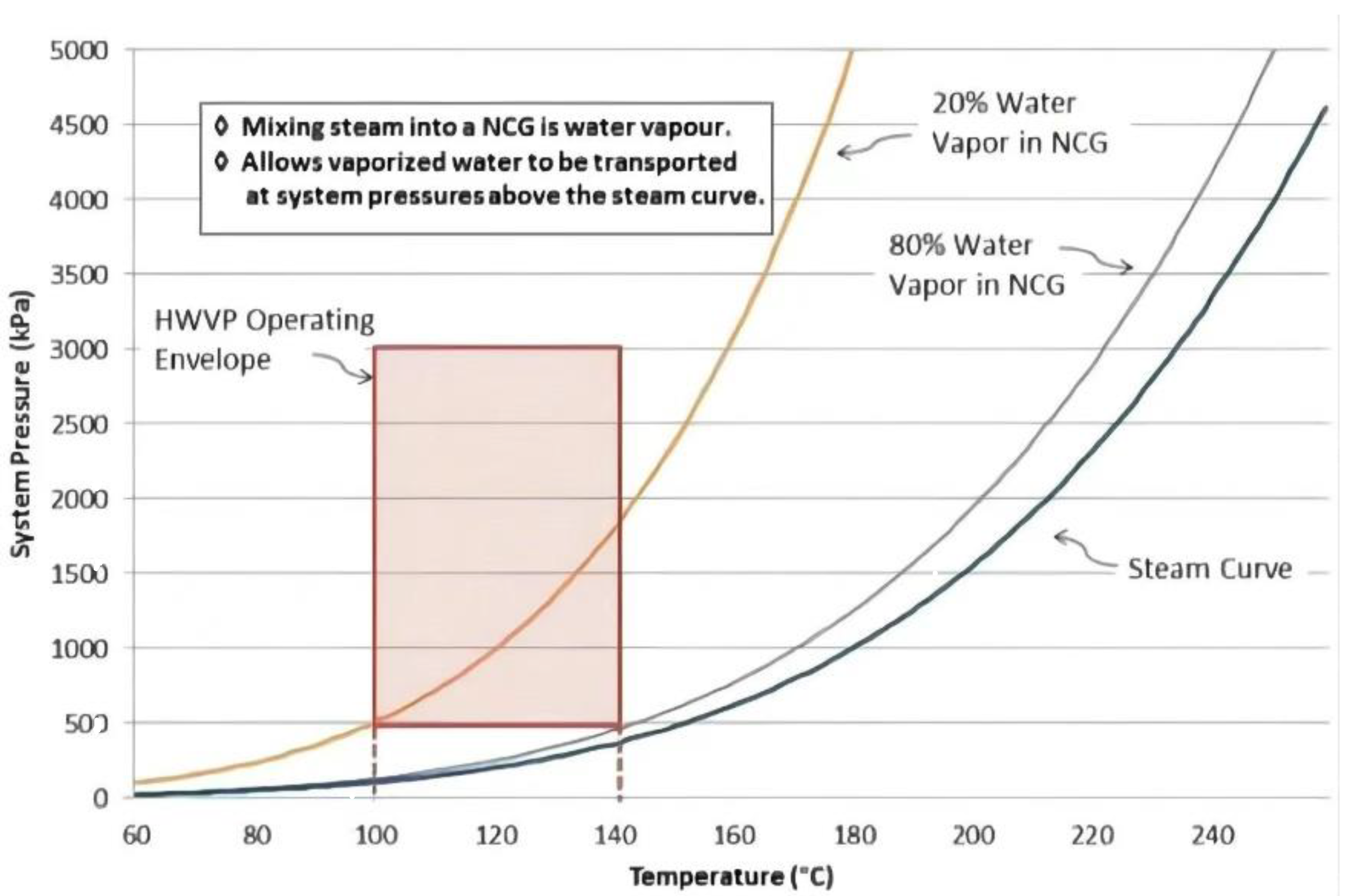
Figure 2.
Schematic diagram of EMVAPEX [23].
Figure 2.
Schematic diagram of EMVAPEX [23].
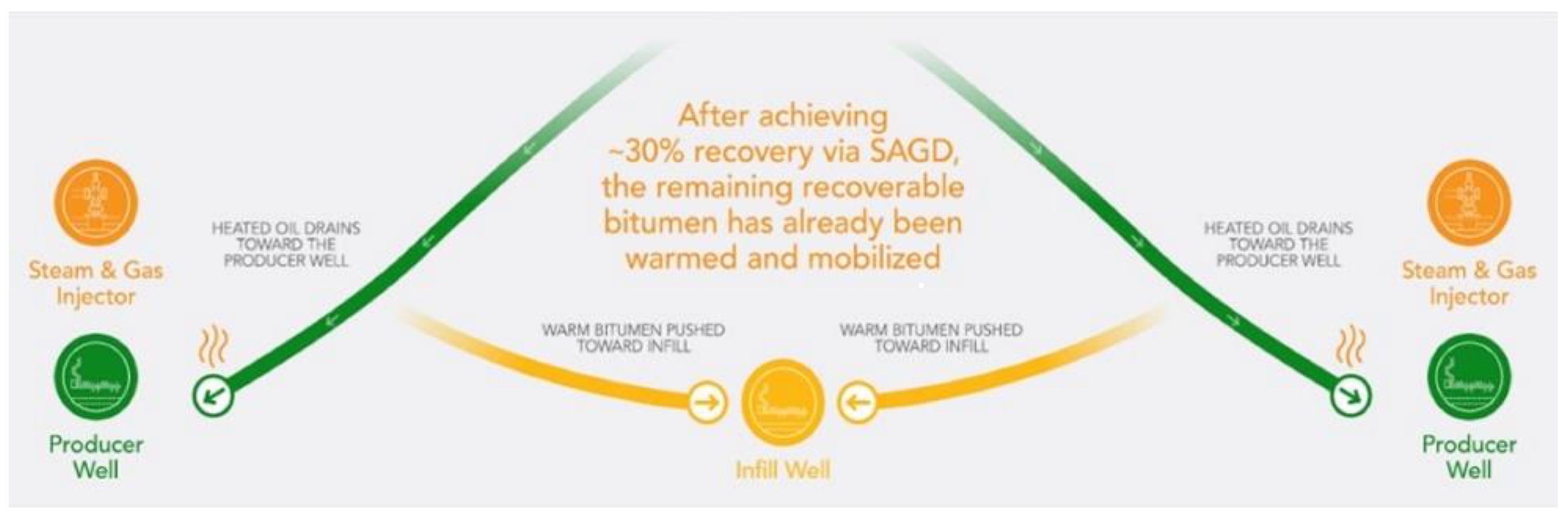
Figure 3.
Schematic diagram of LASER [28].
Figure 3.
Schematic diagram of LASER [28].
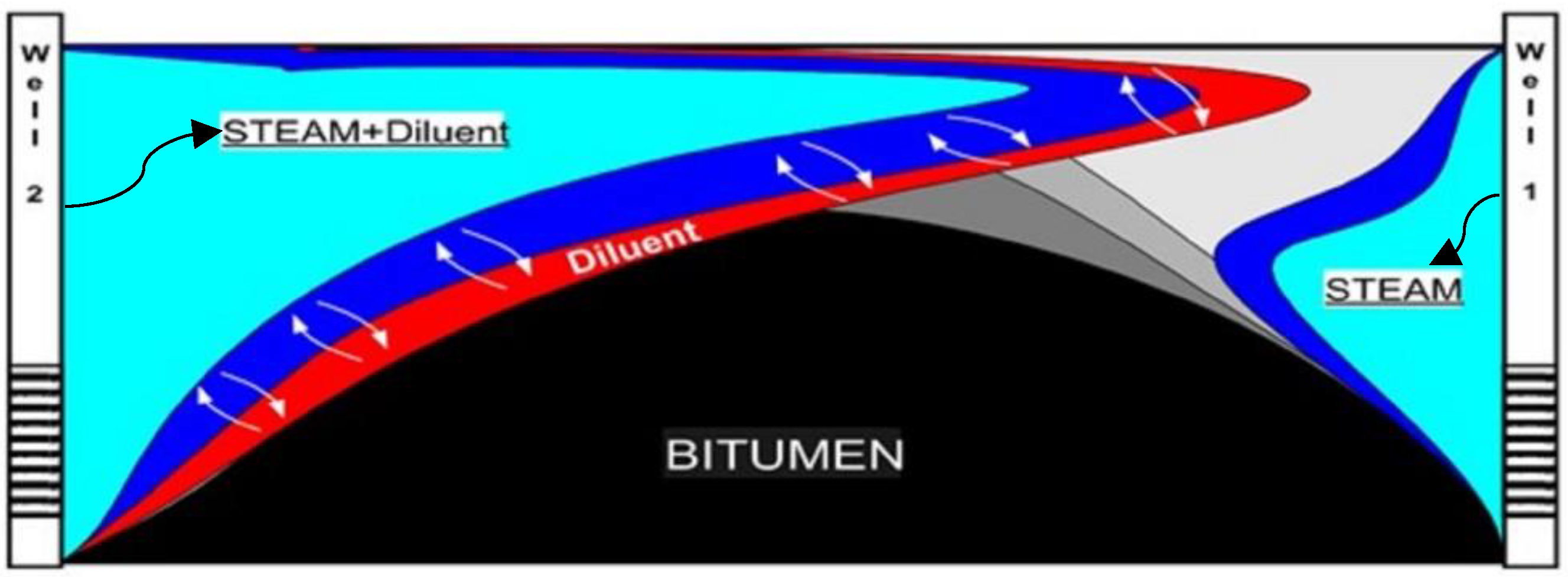
Figure 4.
Schematic diagram of N-SOLV [33].
Figure 4.
Schematic diagram of N-SOLV [33].


Table 1.
Background of some of the technologies and technical ideas.
| Technology | Change | |
|---|---|---|
| LASER | Based on CSS | Steam + solvent (6% vol C5 + condensate) |
| CSP | Based on CSS | Single-component gases of methane, ethane, propane, butane, and CO2 and their two-component gases in two combinations at room temperature |
| CHSI | Based on CSS | Ethane, propane, and other solvents (50 to 100 °C) |
| EMVAPEX | Based on ES-SAGD | SAGD first, then pure solvent gas or solvent + steam (up to 10%) |
| AH-VAPEX | Based on ES-SAGD | a superheated mixture of approximately 90% vol solvent + 10% vol steam (80 °C–170 °C) |
| N-SOLV | Based on ES-SAGD | Light hydrocarbons under certain temperature and pressure conditions (e.g., propane, butane); resistance heating auxiliary thermal solvent |
Table 2.
Comparison of project pilot reservoir parameters.
| Title 1 | EMVAPEX | AH-VAPEX | LASER |
|---|---|---|---|
| Depth (m) | 400–424 | About 200–235 | About 442 |
| Pressure (MPa) | 2.1 | 0.22–0.51 | / |
| Temperature (°C) | 13 | 7 | / |
| Porosity | 0.3–0.36 | 0.34 | 0.3–0.35 |
| Permeability (D) | 2.4–5 | <10 | 0.5–2 |
| Viscosity (reservoir condition, mPa·s) | / | / | 100 |
| Pilot results | 20% increase in production, 5–10% increase in recovery, and approximately 43% reduction in greenhouse gas emissions (compared to SAGD) | Initial investment can be reduced by 50%, crude oil production reaches SAGD level, recovery rate reaches over 70%, and greenhouse gas emissions are reduced by 60% per barrel compared to conventional SAGD | 6–7.5% increase in recovery compared to CSS |
Table 3.
Comparison of indoor experimental parameters.
| N-SOLV [32] | CHSI [38] | CSP (IVORY [39]) | CSP (JAMALOEI [39]) | CSP (Du [39]) | |
|---|---|---|---|---|---|
| Model scale | / | 1550 m3 | 2808.1 m3 | 603.3 m3 | 1830–1860 m3 |
| Porosity | 0.302 | 0.377 | 0.38 | 0.38 | 0.33–0.36 |
| Permeability | 923 D | 2.48 D | 4.5 D | 41.8 D | 5–6 D |
| Viscosity | 15,420 mPa·s (50 °C) | 4330 mPa·s (15 °C) | 39,320 mPa·s (20 °C) | 1080.6 mPa·s (Room temperature) | 2200 mPa·s (21 °C) |
| Gas component | 30% C3 + 70% C4 | C3 | 28% C3 + 72% CO2 | CH4 | C3 |
| Pressure range | 2 MPa | 1.86 MPa | 3.3 MPa | 0.383–2.47 MPa | 0.8 MPa |
| Temperature | 80 °C | 55 °C | 20 °C | 22 °C | 21 °C |
| Experimental results | Recovery rate of 72.1% and solvent recovery rate of 85.1% | Recovery rate of 75%, 10% higher than N-Solv | Oil recovery after primary production and six solvent cycles is 50% | Cycle average recovery factor: 0.09~2.96%; recovery factor: 4.28% | Cycle average recovery factor: 0.41~3.14%; recovery factor: 43.1~60.3% |
| Gravity drainage | √ | × | × | × | × |
| Heat transfer | √ | × | × | × | × |
| Mass transfer | Oil dissolution; oil viscosity reduction | Oil dissolution; oil viscosity reduction; solution gas drive + foamy oil flow | |||
Disclaimer/Publisher’s Note: The statements, opinions and data contained in all publications are solely those of the individual author(s) and contributor(s) and not of MDPI and/or the editor(s). MDPI and/or the editor(s) disclaim responsibility for any injury to people or property resulting from any ideas, methods, instructions or products referred to in the content. |
© 2023 by the authors. Licensee MDPI, Basel, Switzerland. This article is an open access article distributed under the terms and conditions of the Creative Commons Attribution (CC BY) license (https://creativecommons.org/licenses/by/4.0/).
Share and Cite
MDPI and ACS Style
Li, H.; Wang, Q.; Wu, Y. Current Status and Development Direction of Low-Carbon Exploitation Technology for Heavy Oil. Energies 2023, 16, 2219. https://doi.org/10.3390/en16052219
AMA Style
Li H, Wang Q, Wu Y. Current Status and Development Direction of Low-Carbon Exploitation Technology for Heavy Oil. Energies. 2023; 16(5):2219. https://doi.org/10.3390/en16052219
Chicago/Turabian StyleLi, Haifeng, Qiang Wang, and Yongbin Wu. 2023. "Current Status and Development Direction of Low-Carbon Exploitation Technology for Heavy Oil" Energies 16, no. 5: 2219. https://doi.org/10.3390/en16052219
Note that from the first issue of 2016, this journal uses article numbers instead of page numbers. See further details here.