
Application and Verification of a Leg-Transfer Method for Three-Level Active Neutral-Point-Clamped Inverters for Railway Vehicles

1
Department of Electrical Engineering, Gachon University, Seongnam-si 13120, Republic of Korea
2
Korea Railroad Research Institute, Uiwang-si 16105, Republic of Korea
*
Author to whom correspondence should be addressed.
Energies 2024, 17(8), 1967; https://doi.org/10.3390/en17081967
Submission received: 12 December 2023
/
Revised: 16 February 2024
/
Accepted: 23 February 2024
/
Published: 21 April 2024
(This article belongs to the Section F3: Power Electronics)
Abstract
:In this paper, a two-leg-transfer switch structure method that can continuously supply three-phase power even when an accident occurs in a power semiconductor of a three-level active neutral-point-clamped (ANPC) inverter for railway vehicles is presented. The proposed method can minimize the ripple effect caused by power semiconductor faults by separating the faulty leg from the main circuit and connecting the load-side circuit to a neutral point. As a result of simulations, the average values of MAE and RMSE can be reduced by 1.53 [A] and 1.77 [A], respectively, when using the proposed leg-transfer switch structure compared to using the conventional structure. In the IGBT failure experiment, when the proposed method was applied to a three-level ANPC inverter, there was only a 0.21 [%] difference from the THD under normal conditions. As a result, the magnitude, phase, and total harmonic distortion of the three-phase current waveforms measured before and after the fault were identical. Thus, normal three-phase power could be effectively supplied to the load when the proposed leg-transfer switch method was applied after a power semiconductor fault occurred in the three-level ANPC inverter. If this leg-transfer switch method is applied in three-level ANPC inverterd for railway vehicles, track schedule errors can be minimized by continuously supplying three-phase power to the electric motor even when an accident occurs in a power semiconductor.
1. Introduction
Various studies have been conducted on precision control methods for power semiconductors and power conversion systems, and accordingly, various devices using electric motors have been developed [1,2]. Machines propelled by fossil fuels, such as those used in ships, automobiles, and railroads, are being replaced by electric motors [3,4,5,6,7].
Electric motors that can be used in transportation machines vary depending on their purpose or capacity, ranging from induction motors to synchronous motors, brushless DC motors, and permanent magnet synchronous motors [8,9,10].
These electric motors mostly use three-phase power with a phase difference of 120° to generate torque and control the speed of the transportation machines. A three-phase DC/AC inverter that can control the voltage, current, and frequency of the three-phase power is required to control the transportation machines precisely at the speed targeted by the user. Power semiconductors are used in three-phase inverters and can be classified depending on their location and applied control method. Among the DC/AC inverters that can convert DC power into three-phase power, three-level active neutral point clamped (ANPC) inverters can reduce the withstand voltage of the power semiconductors used in two-level inverters and reduce the harmonics of the output according to the increased output level number. Because of these advantages, three-level ANPC inverters are suitable for fields that require high voltages and are widely used in electric motor control. However, if an open- or short-circuit accident occurs in the power semiconductor used in a three-level ANPC inverter for railway vehicles, normal power cannot be supplied to the electric motor. In such cases, running trains may stop, and track schedules may be disrupted. Therefore, a method is required to supply power continuously even when an accident occurs in the power semiconductors that constitute the inverter [11].
Most inverters use three legs; however, methods for supplying three-phase power to a load using only two legs have been studied. These studies have verified that three-phase power can be output if the phases of the voltage and current outputs of the two legs are adjusted [12,13,14]. However, since the structure does not change, it cannot be used as a solution for IGBT failures.
Accordingly, a structure and a control method have been proposed to supply three-phase power to the load by operating only two legs when a leg fault occurs in a two-level three-leg inverter. This method moves the circuit connected to the load side of the faulty leg to the neutral point of the DC link capacitor to output three-phase power with only two legs [15,16,17]. However, this is only available for two-level inverters.
Thereafter, various methods were proposed to supply three-phase power normally to the load, even when a power semiconductor fault occurs in a multilevel-structured inverter [18,19]. Such methods supply normal three-phase power by understanding the characteristics of multiple power semiconductors and performing appropriate control according to the fault cases. However, the methods described above may cause other problems because a faulty power semiconductor is still connected to the main circuit.
Therefore, this paper proposes a two-leg-transfer switch structure method that can provide power continuously even in the event of an accident in a power semiconductor in a three-level ANPC inverter. This method separates the faulty leg from the main circuit and connects the load-side circuit to a neutral point to minimize the ripple effect caused by a fault in the power semiconductor.
The remainder of this paper is organized as follows. In Section 2, the structure and control method of the basic three-level ANPC inverter are described in detail, and the problems in the case of fault occurrence are described. In addition, the proposed leg-transfer switch method is described. In Section 3, a simulation is presented to demonstrate the effects of the proposed leg-transfer switch method. Thereafter, a three-level ANPC inverter is configured as the hardware, and the effect of the proposed method is verified through empirical experiments. Finally, Section 4 summarizes the results of the study and concludes the paper.
2. Analysis of Three-Level ANPC Inverter Structures and the Proposed Leg-Transfer Switch Method
2.1. Analysis the Structure of a Three-Level ANPC Inverter
A three-level ANPC inverter uses active devices for all power devices, including the neutral-point side, to control the power with three levels of output voltage. Figure 1 shows the circuit diagram of a three-level ANPC inverter. The circuit is configured with 18 power semiconductors, as shown in Figure 1, where the DC link capacitor is separated into upper and lower parts, and the neutral point is connected to the power semiconductors of each phase. This structure increases the output voltage in three stages. The three-level ANPC inverter can better reduce the withstand voltage compared to the power semiconductors used in two-level inverters and can reduce the stress on the devices. In addition, it can reduce the harmonics of the output based on the increased number of output levels. Owing to these advantages, it is suitable for fields that require high voltages, and is widely used in motor control [20,21,22,23,24,25].
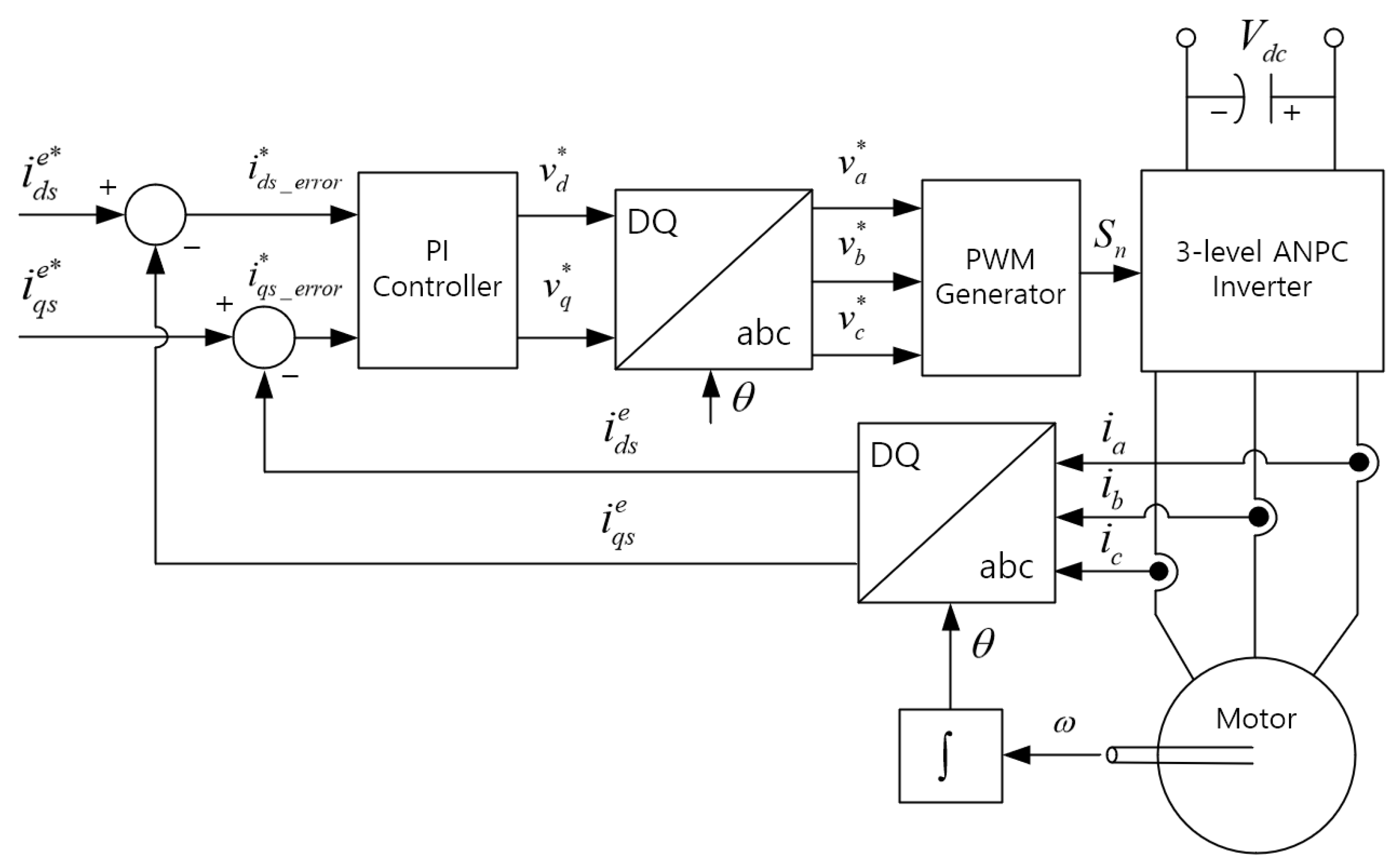
Recently, vector control has been mainly used to control electric motors. Vector control is a method of controlling each component by changing the three-phase voltage and current that change over time into time-invariant voltage and current components; it enables precise speed control because it can control the motor speed instantaneously.
Figure 2 shows a block diagram of the vector control method used in electric motors. Vector control measures the three-phase current applied to the motor and converts it into d-axis (magnetic flux) and q-axis (torque) current components using the DQ transform. The phase necessary at this time is calculated by measuring the rotation speed through an encoder attached to the motor and then integrating it. The current components converted to the d-axis and q-axis create an error between the d-axis current reference and the q-axis current reference necessary for the motor to reach the targeted speed, creating a voltage manipulation amount through the PI controller. The voltage manipulation amount is converted into a three-phase voltage reference through an inverse DQ transform and is converted into On and Off signals through a pulse-width modulation (PWM) generator and injected into each IGBT.
2.2. Limitations of Tolerance Control in Three-Level ANPC Inverters
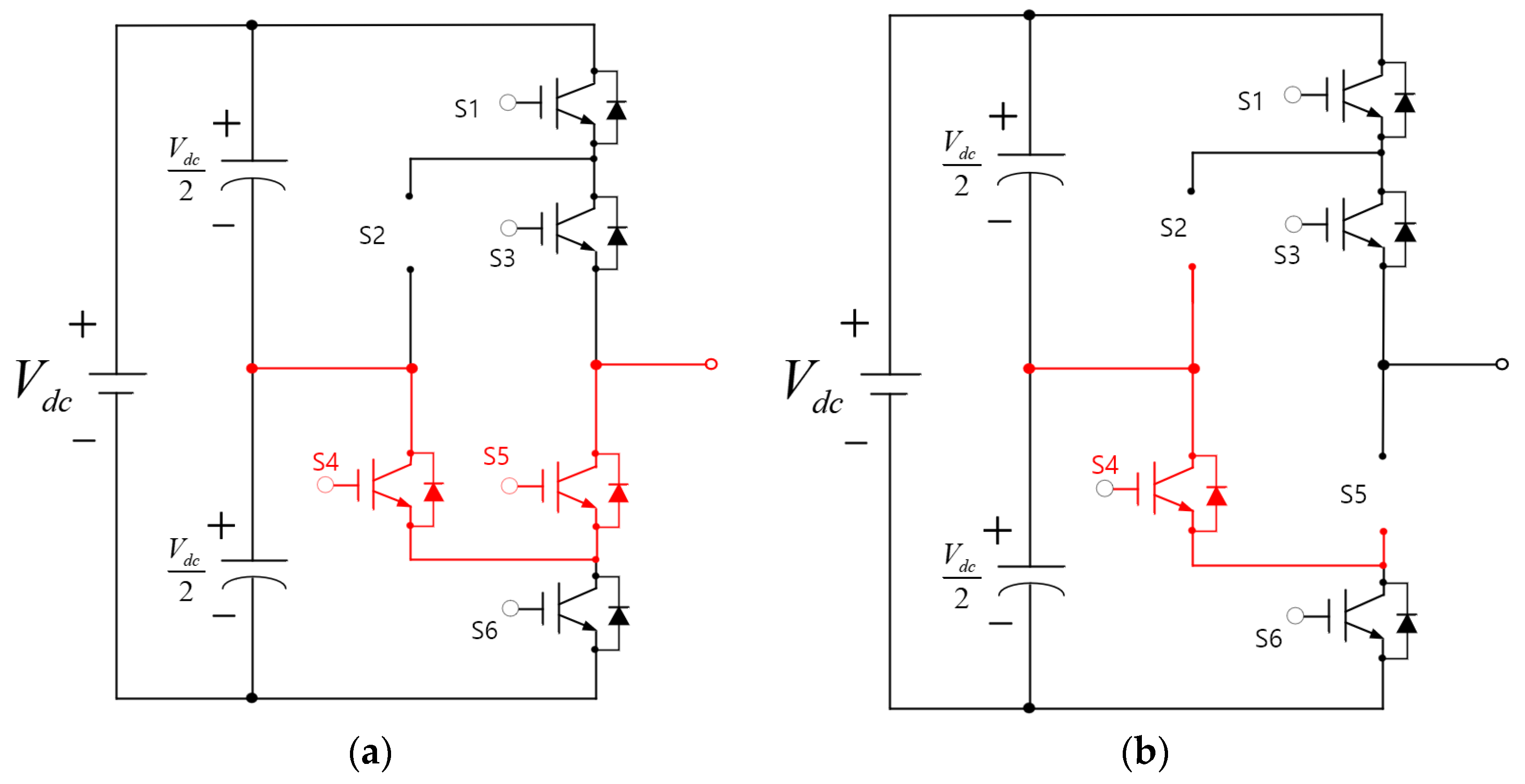
Figure 3 shows an example of the current flow in the faulty leg when conventional tolerance control and the conventional structure are applied. Figure 3a shows the current flow in the S2 fault situation when tolerance control is used. In this case, the current flow can be controlled in a downward direction. Likewise, if a fault occurs in S2 or S3, the current flows to S4 or S5. Conversely, if a fault occurs in S4 or S5, the current flows to the load side through S2 or S3.
Figure 3b shows the current flow when the IGBTs and diodes S2 and S5 are broken. The red line represents the current flow. As shown in Figure 3b, when the IGBT fails, the current from the neutral point cannot flow to the load. This indicates that, when multiple IGBT faults occur, it is difficult to perform tolerance control using a power semiconductor control method.
2.3. Analysis of the Tolerance Control Method by Leg Transfer in the Case of Fault Occurrence in a Three-Level ANPC Inverter
This paper presents a structural method that enables tolerance control even when faults occur in multiple IGBTs. This method separates the faulty leg from the main circuit and connects the circuit to a neutral point on the load side. In addition, a control method that can supply normal three-phase power to the load using only two-leg power semiconductors was adopted and applied.
Figure 4 shows the current flow diagram of the leg when the proposed leg-transfer switch structure was applied. Switches SS1, SS2, and SS3 are added to the proposed leg-transfer switch structure. SS1 and SS3 separate the leg circuit from the main circuit. SS2 connects the circuit on the load side to the neutral point when a fault occurs. SS1, SS2 and SS3 can be configured as single-power relays or magnetic contactors with the contact points 1a2b or 2a1b.
Figure 4a shows the circuit under normal circumstances, where no IGBT fault occurs. The red line represents the current flow. Here, SS1 and SS3 are in a short state so that the legs are connected to the main circuit. SS2 is kept open to prevent the load circuit from being connected directly to a neutral point. Figure 4b shows the circuit when a fault has occurred in the IGBT. Here, SS1 and SS3 change to an open state such that the leg is separated from the main circuit. SS2 is maintained in a short state such that the load-side circuit is directly connected to the neutral point. The switches are located identically on each leg. By operating the relay of the corresponding leg using a signal indicating that a fault has occurred, the legs can be switched, as shown in Figure 4, and tolerance control is possible regardless of which IGBT has experienced a fault.
Figure 5 shows the control block diagram of the three-level ANPC inverter used to supply normal three-phase power to the load after leg transfer. Unlike Figure 2, which is a general control block diagram, an additional control block diagram has been added after the inverse DQ transform. The voltage reference of each phase, which is calculated using the inverse DQ transform, must be converted into a voltage reference suitable for leg transfer. In the steady state, the typical voltage reference can be expressed as follows [17]:
Here, , , and indicate voltage references, indicates the modulation index, and indicates the angular velocity. If a fault occurs in one phase, the voltage references can be converted as follows to generate normal three-phase power with only two legs [17]:
Here, refers to the voltage reference of the faulty leg and can be generated based on signal where the fault is detected. Accordingly, the reference voltage of the faulty leg always has a value of zero, and the remaining voltage references are converted into a waveform with a phase difference of 30°. The signal is converted into On and Off signals through a PWM generator and injected into each IGBT. In addition, based on the signal where a fault is detected, the power relay of the leg should be operated, and an appropriate signal should be injected into the three-level ANPC inverter.
3. Simulation and Experimental Verification According to the Application of theLeg-Transfer Switch Method in a Three-Level ANPC Inverter
3.1. Verification of the Effect of the Leg-Transfer Switch Method through Simulations
Simulations were conducted to analyze the effects of the leg-transfer switch method in the event of a fault in a three-level ANPC inverter. Simulations were conducted using PSIM. The circuit and control diagrams are shown in Figure 5 and Figure 6, respectively, and the parameters are listed in Table 1.
From Table 1, the DC link voltage, , was set to 400 [V], and the capacitor capacity, , was set to 4700 [μF]. A three-phase LR circuit, which is equivalent to an electric motor, was used as the load of the three-level ANPC inverter. Here, the inductor, , was set to 28.14 [mH], and the resistance, , was set to 15 [Ω]. The switching frequencies applied to the individual IGBTs were set to 20 [kHz]. To analyze the effect of the leg-transfer switch method when a three-level ANPC inverter fails, simulations were conducted, assuming that the S8 and S11 IGBTs located in the B-phase leg failed.
Figure 7 shows the current waveform in the case of a phase B fault in the conventional three-level ANPC inverter structure. Figure 7a shows the waveform of the simulation result when the three-level ANPC inverter controls the peak value of the load current to 1 [A], and the fault in the B-phase leg was deliberately caused at 0.05 [s]. Before 0.05 [s], which was before the fault, the three-phase current waveforms were output normally. After 0.05 [s] (after the failure), the waveforms of and appeared distorted, and the current of did not flow.
Figure 7b shows the waveform of the simulation result when the three-level ANPC inverter controlled the peak value of the load current to 5 [A], and the fault in the B-phase leg was deliberately caused at 0.05 [s]. Before 0.05 [s], which was before the fault, the three-phase current waveforms were output normally. After 0.05 [s] (after the failure), the waveforms of and appeared distorted, and the current of did not flow. Accordingly, if two or more IGBTs fail in the conventional three-level ANPC inverter structure, the tolerance control method cannot be performed.
Figure 8 shows the current waveform after the leg transfer in the case of a fault in phase B of the three-level ANPC inverter. Figure 8a shows the waveform of the simulation result when the three-level ANPC inverter controlled the peak value of the load current to 1 [A], and the fault in the B-phase leg was deliberately caused at 0.05 [s]. Before 0.05 [s], which was before the fault, the three-phase current waveforms were output normally. Considering , which was the current flowing from the B-phase load side to the neutral point, no current flowed when SS5 was in an open state.
After 0.05 [s], which was after the fault, the current peak values of were all measured as 1 [A], and the three-phase current with a phase difference of 120° was output normally. Based on , it can be observed that as SS5 changed to the short state, the same current as flowed to the neutral point.
Figure 8b shows the waveform of the simulation results when the three-level ANPC inverter controlled the peak value of the load current at 5 [A] and the fault in the B-phase leg was deliberately caused at 0.05 [s]. Before 0.05 [s], which was before the fault, the current peak values of were all output as 5 [A]. Based on , which was the current flowing from the B-phase load side to the neutral point, no current flowed because SS5 was in an open state.
After 0.05 [s], which was after the fault, the current peak values of were all measured as 5 [A] and the three-phase current with a phase difference of 120° was output normally. Based on , it can be observed that as SS5 changed to a short state, the same current as flowed to the neutral point.
In other words, if the proposed leg-transfer switch method is applied to a three-level ANPC inverter, the faulty leg can be separated from the main circuit, and the circuit on the load side can be connected to the neutral point to supply a normal three-phase current to the load side.
To evaluate the performance of the proposed method, the error and harmonics of the normal current and the measured current were analyzed. In this paper, the mean absolute error (MAE) and root mean square error (RMSE) were utilized to assess the error between the normal current and the measured current [26]. The respective formulas for these metrics are as follows:
Equation (7) represents the formula for calculating the MAE. When the MAE is used, the degree of current error between the normal and measured current can be determined. Therefore, the normal current was used for , and the measured current was applied to to calculate the MAE.
Equation (8) represents the formula for calculating the RMSE. When the RMSE is used, an error less than 1 [A] becomes smaller than the MAE. Therefore, the normal current was used for , and the measured current was applied to to calculate the RMSE, where commonly denotes the total number of samples. The results of calculating the MAE, RMSE, and THD using the conventional method and the proposed method are shown in Figure 9.
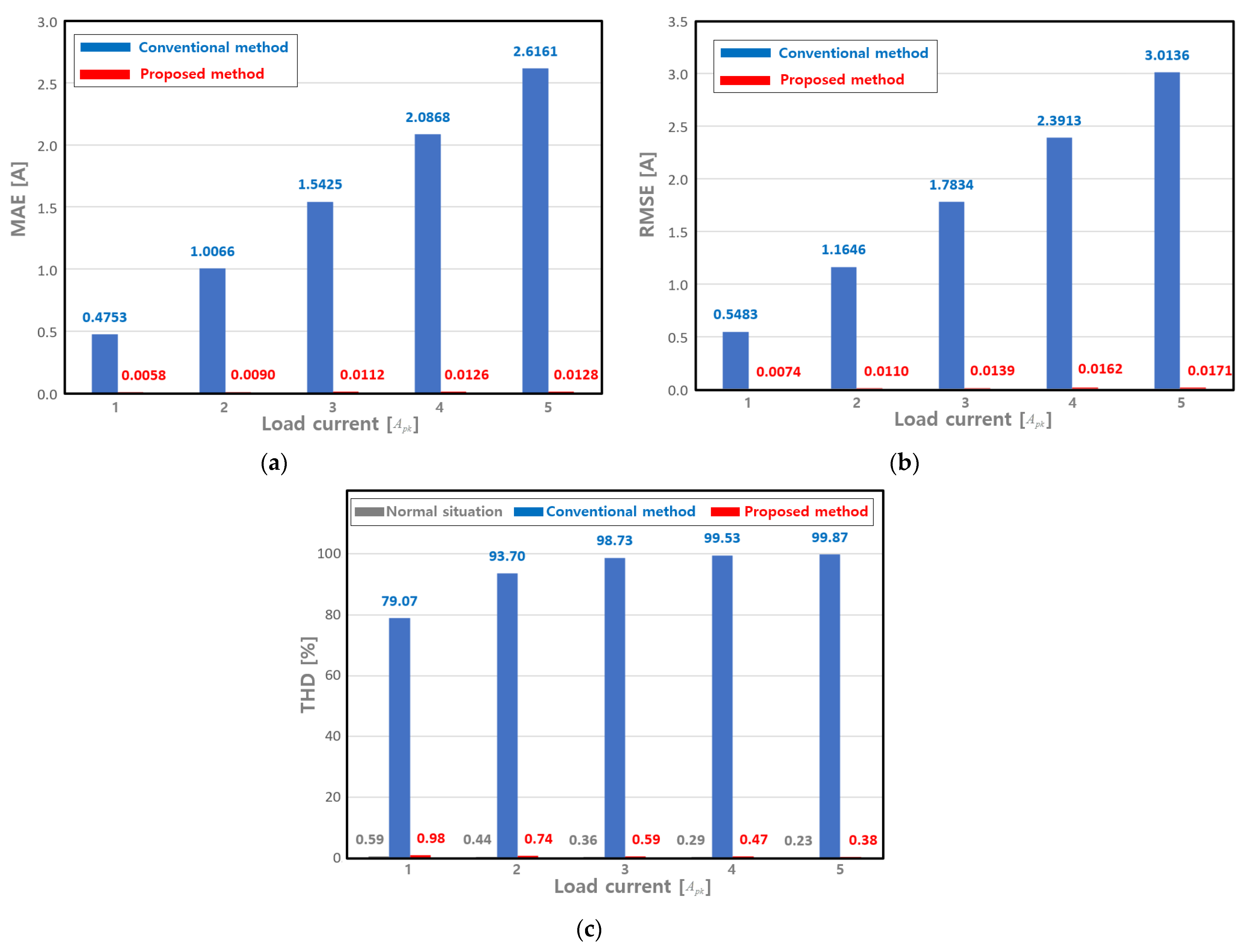
Figure 9 shows the MAE, RMSE, and THD graphs according to the application of the conventional method and the proposed leg-transfer switch structure. The MAE, RMSE, and THD were calculated as the average values of a, b, and c.
Figure 9a shows the graph of the MAE according to the application of the conventional method and the proposed leg-transfer switch structure. When the load current was 1 [] and the conventional method was applied, the MAE was measured to be about 0.47 [A]. When the load current was 5 [] and the conventional method was applied, the MAE was measured to be about 2.16 [A]. It can be seen that the MAE, when using the conventional method, increases as the size of the load current increases. When the proposed leg-transfer switch structure was applied and the load current was 1 [], the MAE was measured to be about 0.0058 [A]. When the load current was 5 [] and the proposed method was applied, the MAE was measured to be about 0.0128 [A]. This shows that if the proposed leg-transfer switch structure is applied to a three-level ANPC inverter, a three-phase current can be supplied more normally than when using the conventional method.
Figure 9b shows a graph of the RMSE according to the application of the conventional method and the proposed method. When the load current was 1 [] and the conventional method was applied, the RMSE was measured to be about 0.54 [A]. When the load current was 5 [] and the conventional method was applied, the RMSE was measured to be about 3.01 [A]. When the proposed method was applied and the load current was 1 [], the RMSE was measured to be about 0.0074 [A]. When the load current was 5 [] and the proposed method was applied, the MAE was measured to be about 0.017 [A]. Looking at the RMSE results, we can confirm once again that if the proposed method is applied to a three-level ANPC inverter, the three-phase current can be supplied more normally than when using the conventional method.
Figure 9c shows a graph of the current THD according to the application of the conventional method and the proposed method. When the conventional method was applied, the THD when the current was 1 [] and 5 [] was measured as 79.07 [%] and 99.87 [%], respectively. When the load current was 1 [] and 5 [], the THD when applying the proposed method was measured to be about 0.98 [%] and 0.38 [%], respectively.
Looking at the THD results, it can be seen that when the proposed leg-transfer switch structure is applied to a three-level ANPC inverter, the THD values measured are similar to those under normal circumstances. This indicates that the proposed leg-transfer switch structure can normally supply a three-phase current in the event of IGBT failure.
3.2. Verification of the Effect of the Leg-Transfer Switch Method through Experiments
An experiment was conducted to analyze the effects of the leg-transfer switch method in the event of a fault in a three-level ANPC inverter in a real environment. The circuit diagram, control diagram, and panoramic view of the experimental environment used are shown in Figure 5, Figure 6, and Figure 8, respectively, and the parameters used are listed in Table 2.
Figure 10 shows a panoramic view of the experimental environment constructed to verify whether the proposed leg-transfer switch method can be applied to a real environment. To verify the suitability of the proposed circuit, the experimental environment was configured using a three-phase LR equivalent circuit. A DC power supply was used as the input for the three-level inverter, and the current flowing to the load side was measured using an oscilloscope. In addition, the harmonics of the load side and three-phase currents were measured before and after the fault using a power quality analyzer.
From Table 2, the DC link voltage, , was set to 400 [V], and the capacitor capacity, , was set to 4700 [μF]. A three-phase LR circuit, which is the equivalent circuit of the electric motor, was used as the load of the three-level ANPC inverter. was set to 28.14 [], and was set to 15 []. The switching frequencies applied to the individual IGBTs were set to 20 []. To analyze the effect of the leg-transfer switch method in the event of a fault in a three-level ANPC inverter, a fault was caused in the C-phase leg, which was identical to that in the simulations.
Figure 11 shows the results of the load-side current and total harmonic distortion (THD) measurement experiments after the application of the proposed leg-transfer switch structure when the load current was 0.5 []. Figure 11a shows the fault signal and three-phase load-current waveforms. Figure 11a shows that the current peak values of before the fault were all measured as 0.5 [A], and a three-phase current with a phase difference of 120° was normally output.
After the fault, in Figure 11a, the current peak values of were all measured as 0.5 [A], and the three-phase current was output normally, identical to that before the fault. This indicates that the leg-transfer switch method can operate normally in actual experiments. In particular, based on the current waveform of phase C, it can be observed that the current THD after the fault decreased compared with the current THD before the fault.
Based on Figure 11b, which shows the current THD values measured before the fault, the THDs of were measured as 11.9 [%], 11.3 [%], and 11.8 [%], respectively. However, in Figure 11c, which shows the current THD values measured after the fault, the THDs values of were measured as 11.1 [%], 10.4 [%], and 9.7 [%], respectively. Here, the THD of after the fault was reduced by approximately 2.1 [%] compared with that before the fault. This indicates that the power semiconductor of phase C was separated from the circuit and thus did not operate, and that the THD of the current of phase C was reduced because the three-phase power was supplied only through the power semiconductors located in phases A and B.
That is, based on the waveforms and THD values of measured before and after the fault when the load current was 0.5 [], it could be verified that the proposed leg-transfer switch method applied to the three-level ANPC inverter operated effectively.
Figure 12 shows the results of the load-side current and THD measurement experiments after the application of the proposed leg-transfer switch structure when the load current was 5 []. Figure 12a shows the fault signal and three-phase load-current waveforms. In Figure 12a, the current peak values of before the fault were all measured as 5 [A], and a three-phase current with a phase difference of 120° was normally output.
After the fault, in Figure 12a, the current peak values of were all measured as 5 [A], and the three-phase current output was normal, identical to that before the fault. However, unlike in Figure 11a, current distortion occurred for approximately 7 [ms] during the process of switching the leg. This indicates that the leg-transfer switch method can operate normally in the actual experiments; however, delays may occur during the transfer process. Based on the current waveform of phase C, it can be observed that the current THDs before and after the fault are similar.
Figure 12b shows the current THD values measured before the fault. The THDs of were measured as 1.7 [%], 1.7 [%], and 1.8 [%], respectively. Figure 12c shows the current THD values measured after the fault. The THDs of were measured as 1.8 [%], 1.9 [%], and 1.9 [%], respectively. Thus, as the magnitude of the current supplied to the load increased, the THD decreased, and the same result was obtained even when the legs were switched. That is, when the load current was 5 [], based on the waveforms and THD values of measured before and after the fault, it was verified that the proposed leg-transfer switch method applied to the three-level ANPC inverter operated effectively, even when the magnitude of the current varied.
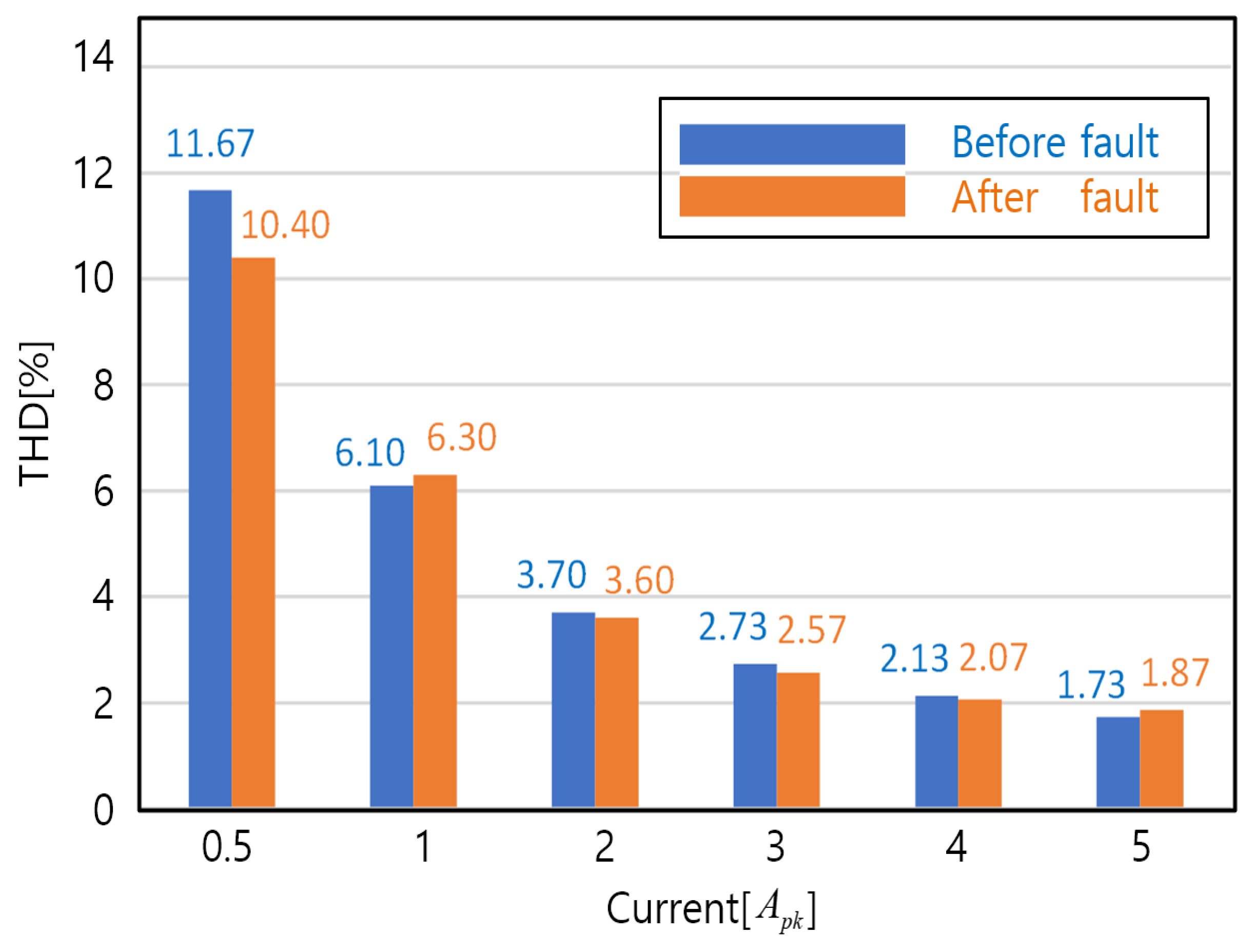
Figure 13 shows a graph of the THDs measured according to the load current magnitude. The smaller the current, the smaller the C-phase current THD after the fault compared with the C-phase current THD before the fault. Conversely, as the current increased, the C-phase current THD after the fault was the same as the C-phase current THD before the fault. This indicates that the THD of the current of phase C was reduced because the power semiconductor of phase C was separated from the circuit and did not operate, and three-phase power was supplied with only the power semiconductors located in phases A and B.
Figure 14 shows a graph of the averages of the current THDs measured according to the load current magnitude. In Figure 13, a, b, and c refer to A-phase, B-phase, and C-phase, respectively. The smaller the current, the smaller the average THD after the fault compared with the THD before the fault. Conversely, as the magnitude of the current increased, the THD after the fault was the same as the THD before the fault. This can be interpreted as a result of the fact that the C-phase current THD decreased because the C-phase power semiconductor was separated from the circuit and did not operate after the fault.
It can be verified that normal three-phase power can be effectively supplied to the load by applying the proposed leg-transfer switch method when a fault occurs in the power semiconductor in a three-level ANPC inverter.
4. Conclusions
This paper presented a two-leg-transfer switch structure method that can continuously supply three-phase power even when an accident occurs in the power semiconductor of a three-level ANPC inverter for railway vehicles. The current flow when a fault occurs in a power semiconductor in a three-level ANPC inverter was analyzed, and a tolerance control method that can be used when a fault occurs in a three-level ANPC inverter was investigated. Thereafter, the problems that arise when faults occur in multiple power semiconductors were described. The leg-transfer switch method could minimize the ripple effect caused by a fault in the power semiconductor by separating the faulty leg from the main circuit and connecting the load circuit to a neutral point. In addition, the voltage reference conversion that can be used for leg switching was analyzed.
A simulation was conducted to verify the effect of applying the proposed leg-transfer switch method to a three-level ANPC inverter. When a conventional structure was used in the simulation, the average values of MAE, RMSE, and THD were measured to be 1.54 [A], 1.78 [A], and 94.18 [%], respectively. In contrast, when the proposed leg-transfer switch structure was applied to a three-level ANPC inverter, the average values of MAE, RMSE, and THD were measured to be 0.01 [A], 0.01 [A], and 0.63 [%], respectively. The simulation results confirmed that the magnitudes and phases of the three-phase current waveforms measured before and after the fault were identical.
An experiment was conducted to verify the effect of applying the proposed leg-transfer switch method in a real environment. When the proposed method in the experiment was applied to a three-level ANPC inverter, the average THD value was calculated to be 4.67 [%] under normal conditions. Additionally, the average THD value when a failure occurred was measured at 4.46 [%]. Experiments were conducted at various current magnitudes, and it was determined that the magnitudes and phases of the three-phase current waveforms measured before and after the fault were the same for all current magnitudes. Additionally, the smaller the current, the smaller the average THD after the fault, compared with the THD before the fault. In contrast, as the current increased, the THD after the fault became the same as the THD before the fault. That is, it was verified that normal three-phase power can be effectively supplied to the load by applying the proposed leg-transfer switch method when a fault occurs in a power semiconductor in a three-level ANPC inverter.
If the leg-transfer switch method is applied to three-level ANPC inverters for railway vehicles, track schedule errors can be minimized by continuously supplying three-phase power to the electric motor, even when an accident occurs in a power semiconductor. However, since this study verified the effectiveness using only the LR equivalent circuit, it is judged necessary to further verify the effect of applying it to various motors that can be used in railway vehicles. Additionally, there is a need to further study ways to reduce delays during leg transfer.
Author Contributions
Conceptualization, H.L. and J.S.; methodology, H.L. and J.S.; resource, G.K.; funding acquisition, G.K.; software, H.L.; validation, J.S.; formal analysis, H.L.; writing—original draft preparation, H.L.; project administration, G.K. and J.S.; writing—review and editing, H.L., and J.S.; supervision, J.S. All authors have read and agreed to the published version of the manuscript.
Funding
This research was supported by a grant from the R&D program (PK2303F1) from the Korea Railroad Research Institute. This work was also supported by the Korea Institute of Energy Technology Evaluation and Planning (KETEP) and the Ministry of Trade, Industry, and Energy (MOTIE) of the Republic of Korea (No. 20214000000060).
Data Availability Statement
Data are contained within the article.
Conflicts of Interest
The authors declare no conflicts of interest.
References
- Sustainable Development Solutions Network. America’s Zero Carbon Action Plan; Sustainable Development Solutions Network: New York, NY, USA, 2020; p. 27. [Google Scholar]
- The Government of the Republic of Korea. 2050 Carbon Neutral Strategy of the Republic of Korea Towards a Sustainable and Green Society; The Government of the Republic of Korea: Seoul, Republic of Korea, 2020; pp. 16–17.
- Yao, M.; Qin, D.; Zhou, X.; Zhan, S.; Zeng, Y. Integrated optimal control of transmission ratio and power split ratio for a CVT-based plug-in hybrid electric vehicle. Mech. Mach. Theory 2019, 136, 52–71. [Google Scholar] [CrossRef]
- Hasoun, M.; Afia, A.E.; Chikh, K.; Khafallah, M.; Benkirane, K. A PWM Strategy for Dual Three-Phase PMSM Using 12-Sector Vector Space Decomposition for Electric Ship Propulsion. In Proceedings of the 19th IEEE MELECON, Marrakech, Morocco, 2–7 May 2018; pp. 243–248. [Google Scholar] [CrossRef]
- Sieklucki, G. Optimization of Powertrain in EV. Energies 2021, 14, 725. [Google Scholar] [CrossRef]
- Hu, X.; Martinez, C.M.; Yang, Y. Charging, power management, and battery degradation mitigation in plug-in hybrid electric vehicles: A unified cost-optimal approach. Mech. Syst. Signal Process. 2017, 87, 4–16. [Google Scholar] [CrossRef]
- Hasoun, M.; EI Afia, A.; Chikh, K.; Khafallah, M. Field Oriented Control of Dual Three-Phase PMSM Based Vector Space Decomposition for Electric Ship Propulsion. In Proceedings of the IEEE ICCSRE, Agadir, Morocco, 22–24 July 2019; pp. 1–6. [Google Scholar] [CrossRef]
- Jeong, M.T.; Lee, K.B.; Pyo, H.Y.; Nam, D.W.; Kim, W.H. A Study on the Shape of the Rotor to Improve the Performance of the Spoke-Type Permanent Magnet Synchronous Motor. Energies 2021, 14, 3785. [Google Scholar] [CrossRef]
- Pillay, P.; Knshnan, R. Modeling of Permanent Magnet Motor Drives. IEEE Trans. Ind. Electron. 2008, 55, 2246–2257. [Google Scholar] [CrossRef]
- Tong, W.; Dai, S.; Wu, S.; Tang, R. Performance Comparison Between an Amorphous Metal PMSM and a Silicon Steel PMSM. IEEE Trans. Magn. 2019, 55, 8102705. [Google Scholar] [CrossRef]
- Lee, J.S.; Choi, U.M. Velocity Profile-Based Evaluation and Improvement of Lifetime of Power Devices in Railway PropulsionInverters. IEEE J. Emerg. Sel. Top. Power Electron. 2022, 10, 1384–1394. [Google Scholar] [CrossRef]
- Phurahong, T. Design of 2-Leg Inverter for Controlling of a Single Phase Induction Motor. In Proceedings of the 2020 3rd International Conference on Power and Energy Applications (ICPEA), Busan, Republic of Korea, 24–26 April 2020; pp. 117–120. [Google Scholar]
- Chikate, V.D.; Fadnis, A.Y.; Gondhalekar, G.C. Control of 2-Ph. Induction Motor Using 2-Leg Inverter. In Proceedings of the 2018 International Conference on Smart Electric Drives and Power System (ICSEDPS), Maharashtra, India, 12–13 June 2018; pp. 369–374. [Google Scholar]
- Jacobina, C.B.; De Rossiter Correa, M.B.; Da Silva, E.R.C.; Lima, A.M.N. Induction motor drive system for low-power applications. IEEE Trans. Ind. Appl. 1999, 35, 52–61. [Google Scholar] [CrossRef]
- Jabbar, M.A.; Khambadkone, A.M.; Zhang, Y. DSP based space vector PWM drive for constant power operation of two-phase induction motors. In Proceedings of the IECON’01. 27th Annual Conference of the IEEE Industrial Electronics Society (Cat. No. 37243), Denver, CO, USA, 29 November–2 December 2001; Volume 2, pp. 1166–1171. [Google Scholar]
- Liu, Q.-Z. A Control Concept of SVM for Two Legs Inverters. In Proceedings of the 2021 4th International Conference on Advanced Electronic Materials, Computers and Software Engineering (AEMCSE), Changsha, China, 26–28 March 2021; pp. 318–321. [Google Scholar]
- Blaabjerg, F.; Neacsu, D.O.; Pedersen, J.K. Adaptive SVM to compensate DC-link voltage ripple for four-switch three-phase voltage-source inverters. IEEE Trans Power Electron. 1999, 14, 743–752. [Google Scholar] [CrossRef]
- Do, D.T.; Tran, V.T.; Nguyen, M.K.; Naik, S.M. Fault Tolerant Control Methods for Three-Level Boost T-Type Inverter. IEEE Trans. Ind. Electron. 2023, 70, 5463–5473. [Google Scholar] [CrossRef]
- Chao, K.H.; Ke, C.H. Fault Diagnosis and Tolerant Control of Three-Level Neutral-Point Clamped Inverters in Motor Drives. Energies 2020, 13, 6302. [Google Scholar] [CrossRef]
- Wang, M.Z.; Sun, D.; Zheng, Z.H.; Nian, H. A Novel Lookup Table Based Direct Torque Control for OW-PMSM Drives. IEEE Trans. Ind. Electron. 2021, 68, 10316–10320. [Google Scholar] [CrossRef]
- Manzolini, V.; Rù, D.D.; Bolognani, S. An Effective Flux Weakening Control of a SyRM Drive Including MTPV Operation. IEEE Trans. Ind. Appl. 2019, 55, 2700–2709. [Google Scholar] [CrossRef]
- Kim, S.H.; Sul, S.K. Maximum Torque Control of an Induction Machine in the Field Weakening Region. IEEE Trans. Ind. Appl. 1995, 31, 787–794. [Google Scholar] [CrossRef]
- Ye, M.T.; Shi, T.N.; Wang, H.M.; Li, X.M.; Xia, C.L. Sensorless-MTPA Control of Permanent Magnet Synchronous Motor Based on an Adaptive Sliding Mode Observer. Energies 2019, 12, 3773. [Google Scholar] [CrossRef]
- Lee, D.Y.; Lee, J.H. Compensation of Interpolation Error for Look-Up Table-Based PMSM Control Method in Maximum Power Control. Energies 2021, 14, 5526. [Google Scholar] [CrossRef]
- Xu, X.; Novotny, D.W. Selecting the flux reference for induction machine drives in the field weakening region. IEEE Trans. Ind. Appl. 1992, 28, 1353–1358. [Google Scholar] [CrossRef]
- Lee, J.; Park, K.; Cho, J.; Kim, J.; Son, S. Novel monitoring system, for low-voltage DC distribution network using deep-learning-based disaggregation. IEEE Access 2020, 8, 185266–185275. [Google Scholar] [CrossRef]
Figure 1.
Circuit diagram of a three-level ANPC inverter.
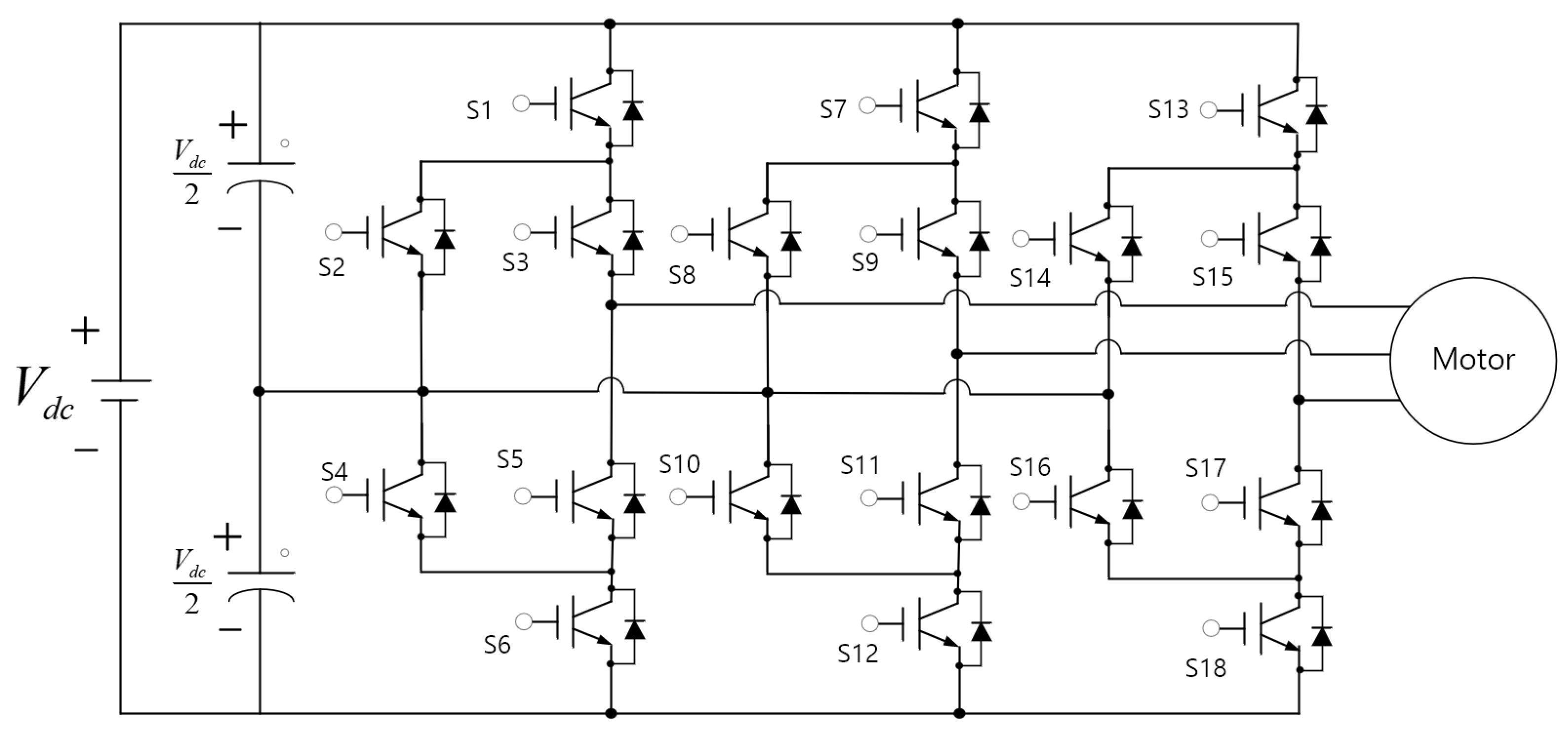
Figure 2.
Control block diagram of a three-level ANPC inverter.

Figure 3.
Current flow diagram of the leg where an IGBT fault occurs: (a) S2 fault; (b) S2, S5 fault.
Figure 3.
Current flow diagram of the leg where an IGBT fault occurs: (a) S2 fault; (b) S2, S5 fault.

Figure 4.
Current flow diagram of the leg when the proposed leg-transfer switch structure is applied; (a) normal condition. (b) S2, S5 fault.
Figure 4.
Current flow diagram of the leg when the proposed leg-transfer switch structure is applied; (a) normal condition. (b) S2, S5 fault.
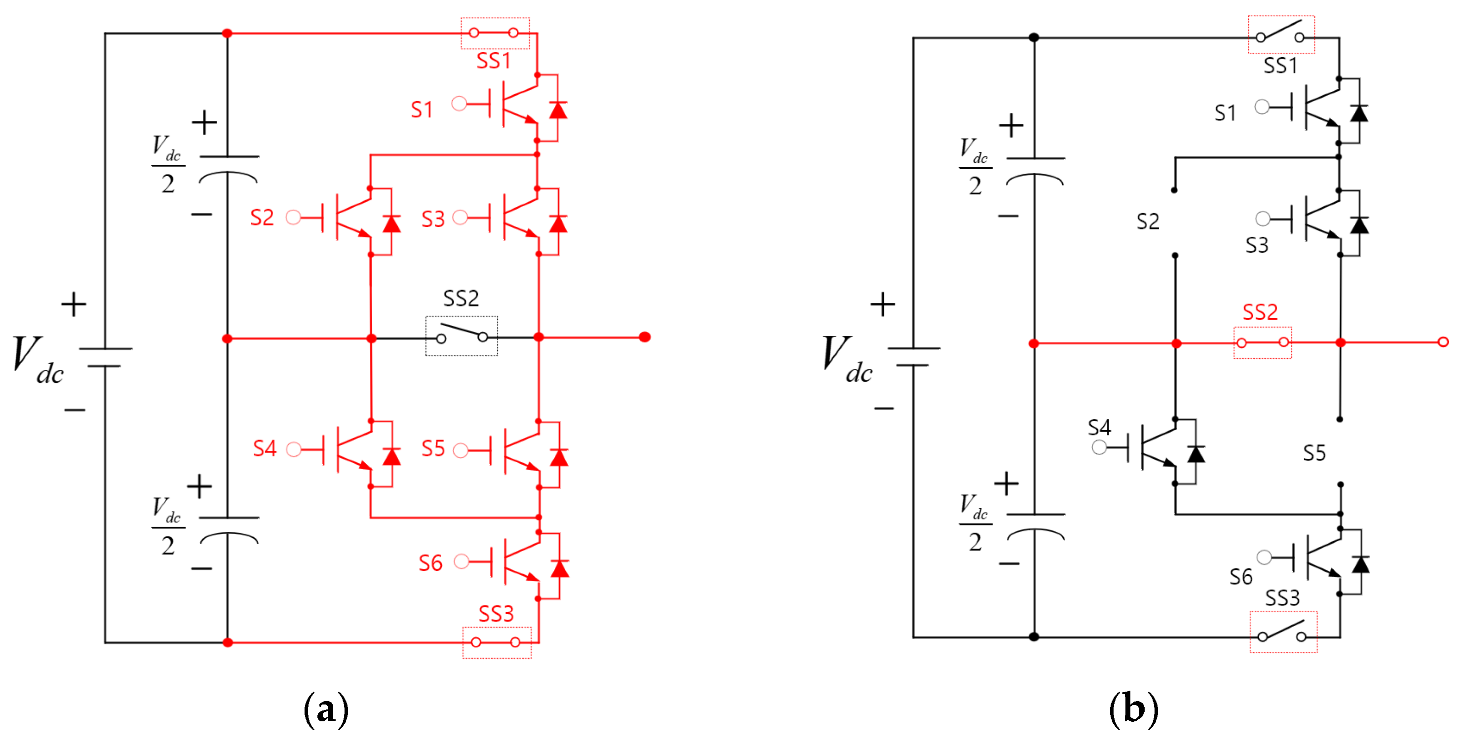
Figure 5.
Control block diagram of a three-level ANPC inverter for the application of the leg-transfer switch method.
Figure 5.
Control block diagram of a three-level ANPC inverter for the application of the leg-transfer switch method.
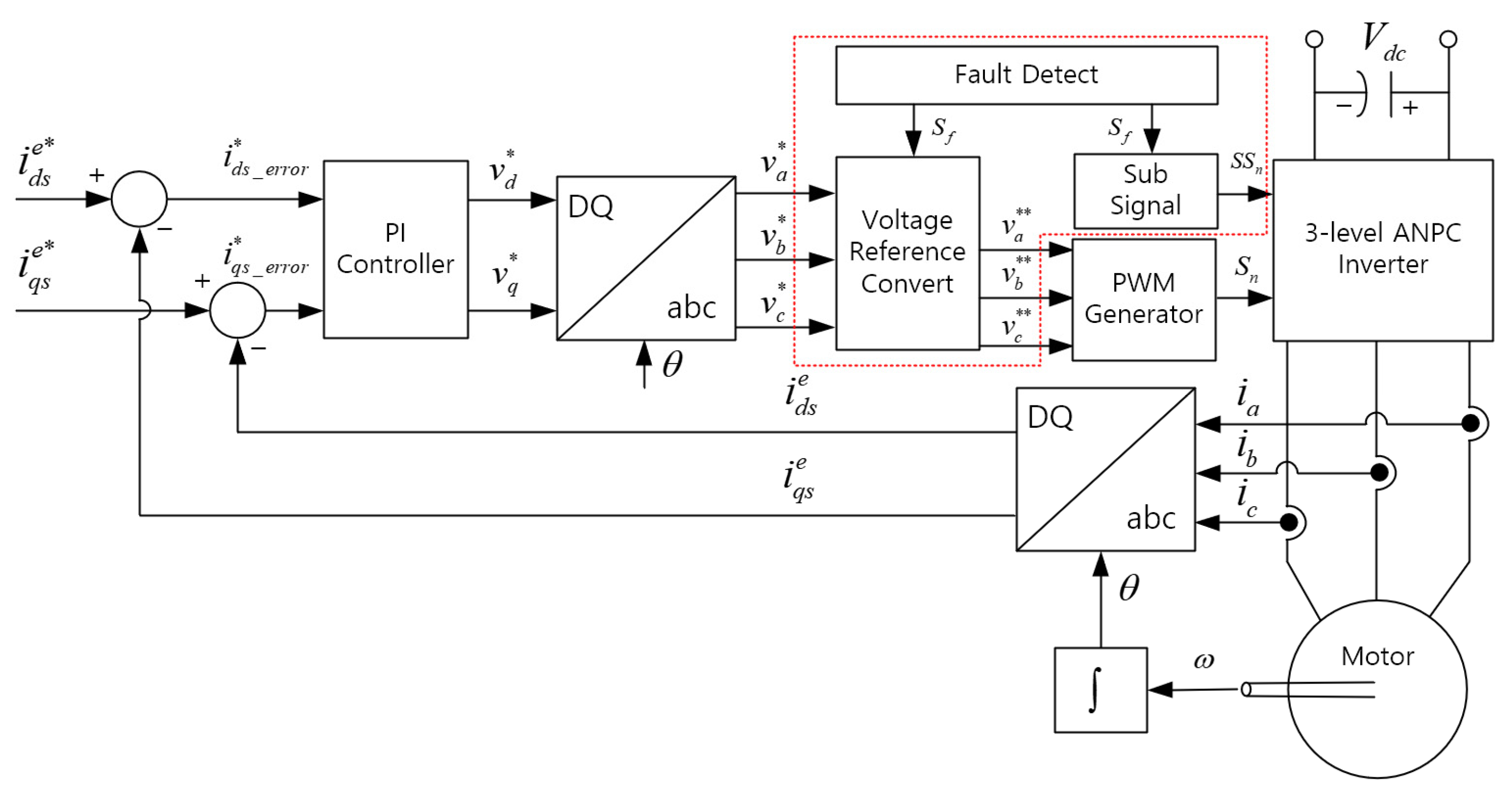
Figure 6.
Circuit diagram of a three-level ANPC inverter using the leg-transfer switch method.

Figure 7.
Waveforms in the load-side current measurement simulations for the application of the conventional structure. (a) When the load current is 1 [Apk]; (b) when the load current is 5 [Apk].
Figure 7.
Waveforms in the load-side current measurement simulations for the application of the conventional structure. (a) When the load current is 1 [Apk]; (b) when the load current is 5 [Apk].
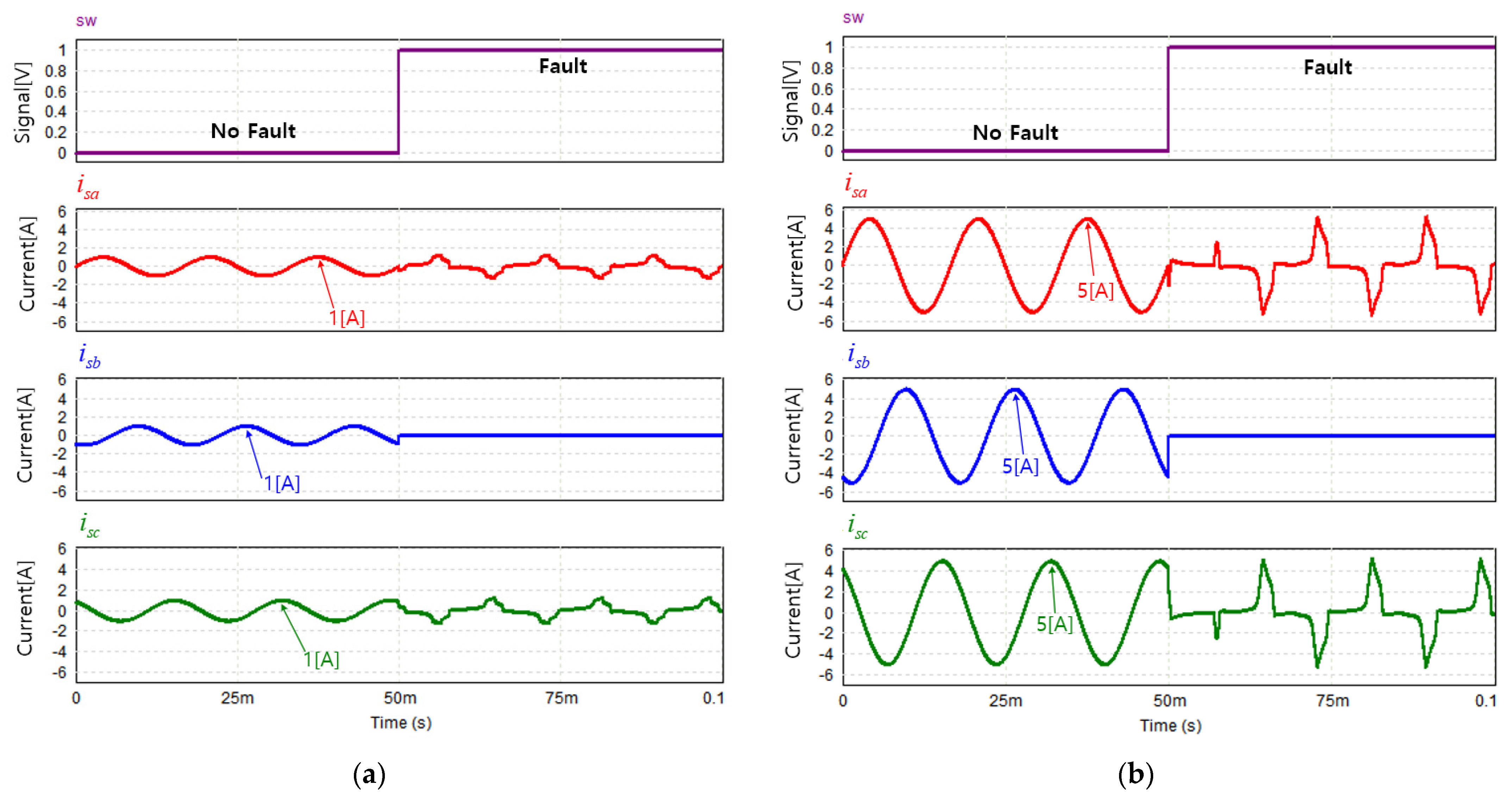
Figure 8.
Waveforms in the load-side current measurement simulations for the application of the proposed leg-transfer switch structure. (a) When the load current is 1 [Apk]; (b) when the load current is 5 [Apk].
Figure 8.
Waveforms in the load-side current measurement simulations for the application of the proposed leg-transfer switch structure. (a) When the load current is 1 [Apk]; (b) when the load current is 5 [Apk].
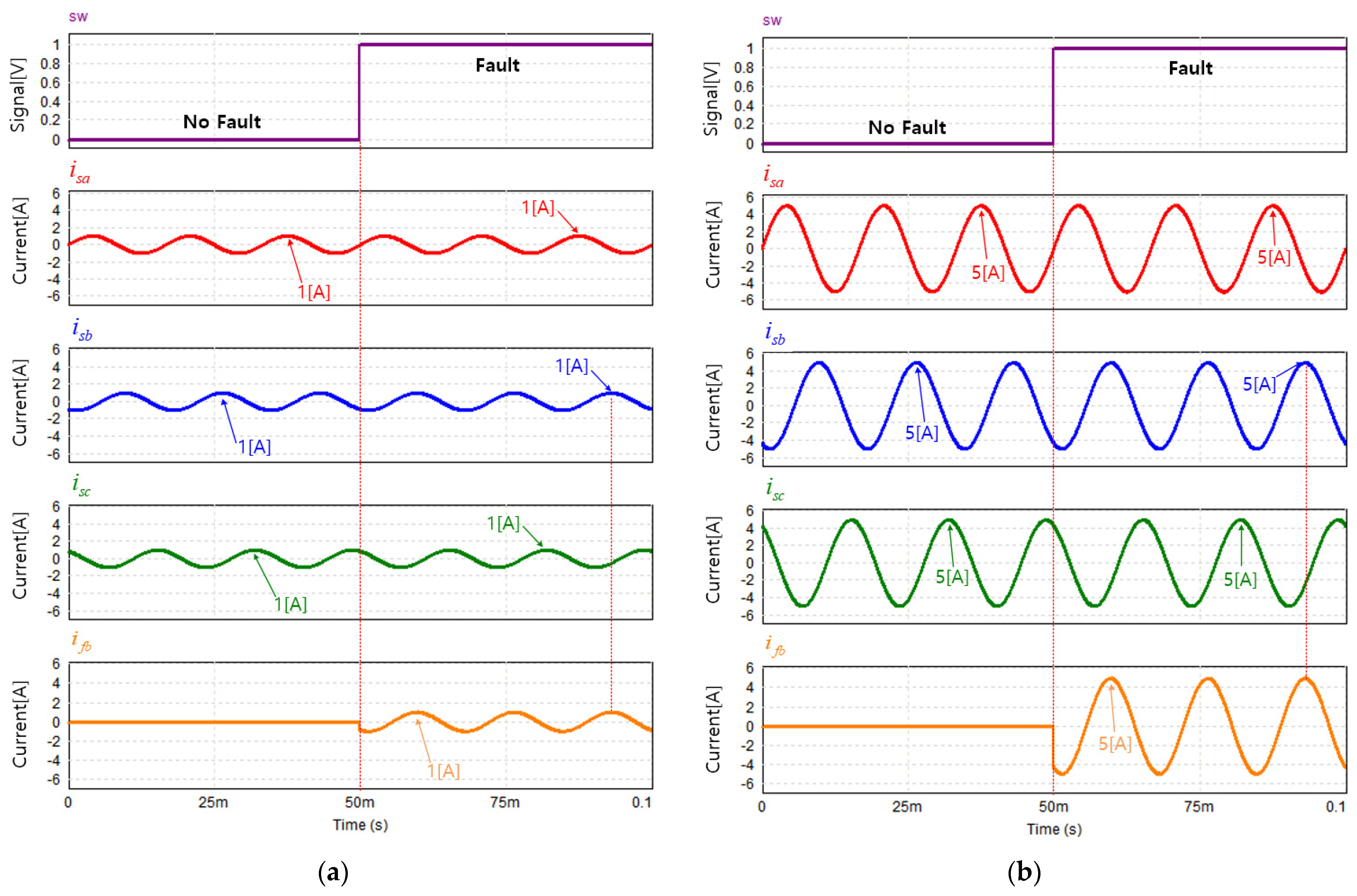
Figure 9.
Result graphs according to application of conventional method and proposed leg-transfer switch structure: (a) MAE result; (b) RMSE result; (c) load current THD result.
Figure 9.
Result graphs according to application of conventional method and proposed leg-transfer switch structure: (a) MAE result; (b) RMSE result; (c) load current THD result.

Figure 10.
Panoramic view of the experimental environment.
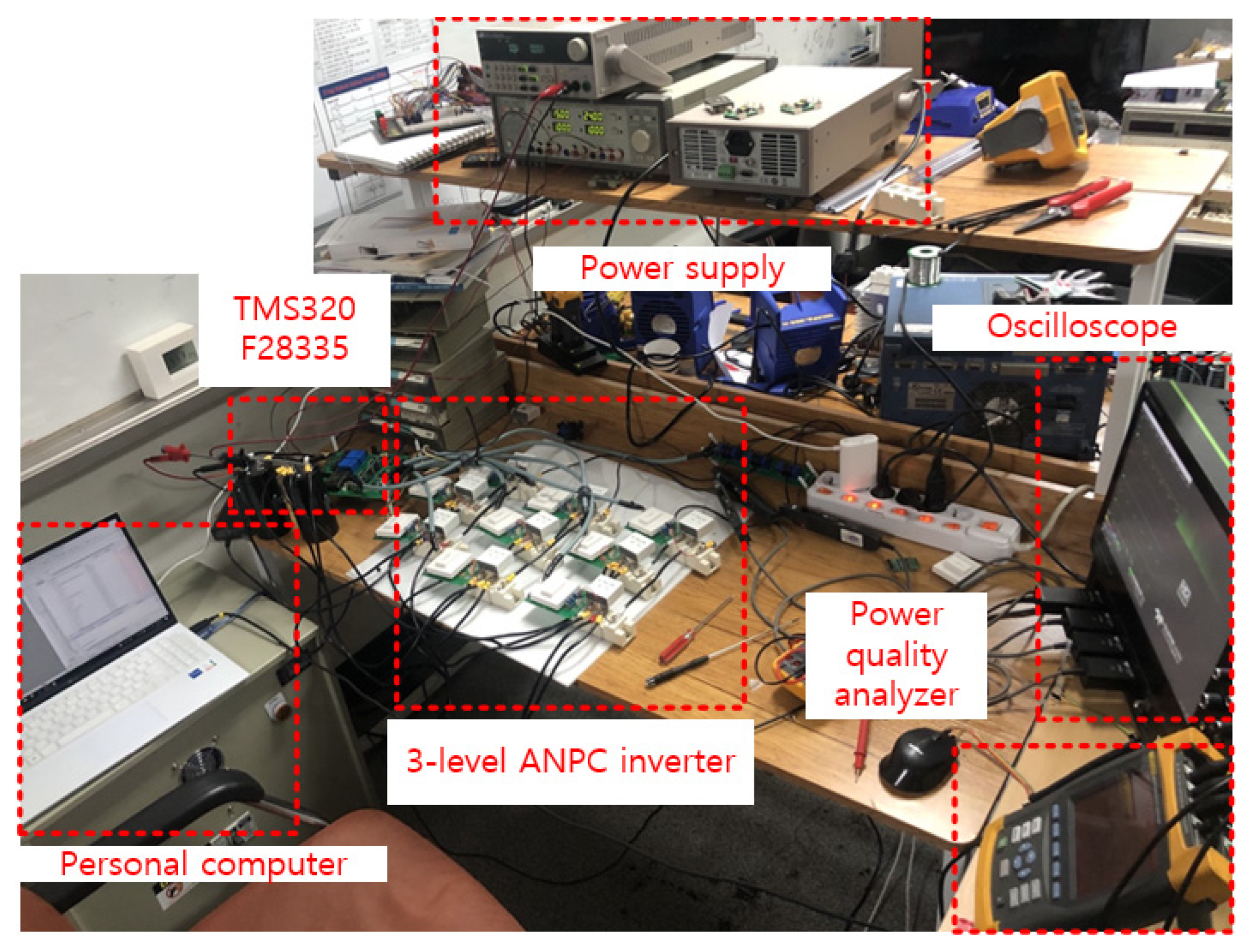
Figure 11.
Experimental results of the application of the proposed leg-transfer switch structure when the load current was 0.5 [Apk]. (a) Load current waveform; (b) load current THD before the fault; (c) load current THD after the fault.
Figure 11.
Experimental results of the application of the proposed leg-transfer switch structure when the load current was 0.5 [Apk]. (a) Load current waveform; (b) load current THD before the fault; (c) load current THD after the fault.
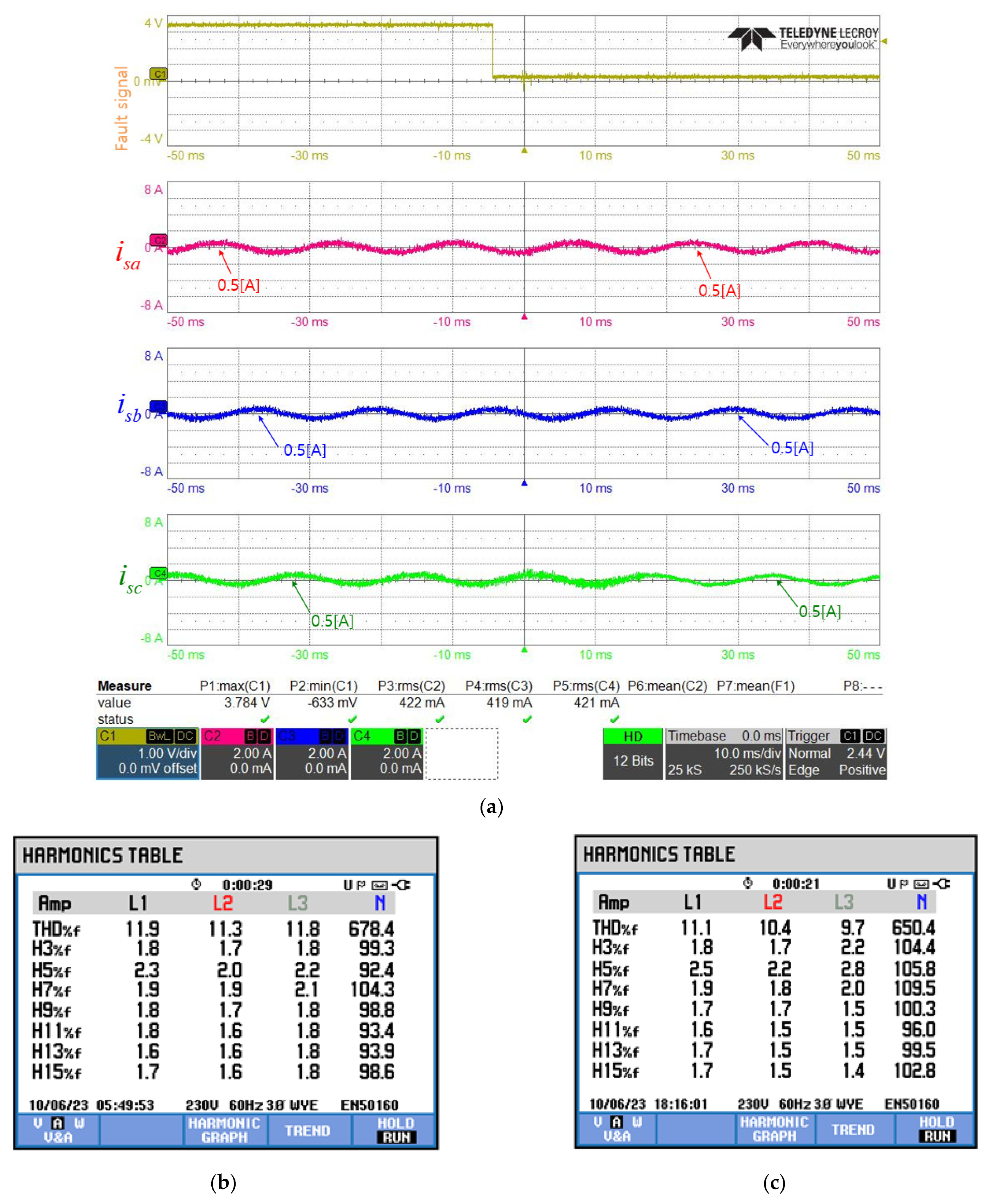
Figure 12.
Experimental results of the application of the proposed leg-transfer switch structure when the load current was 5 [Apk]. (a) Load current waveform; (b) load current THD before the fault; (c) load current THD after the fault.
Figure 12.
Experimental results of the application of the proposed leg-transfer switch structure when the load current was 5 [Apk]. (a) Load current waveform; (b) load current THD before the fault; (c) load current THD after the fault.
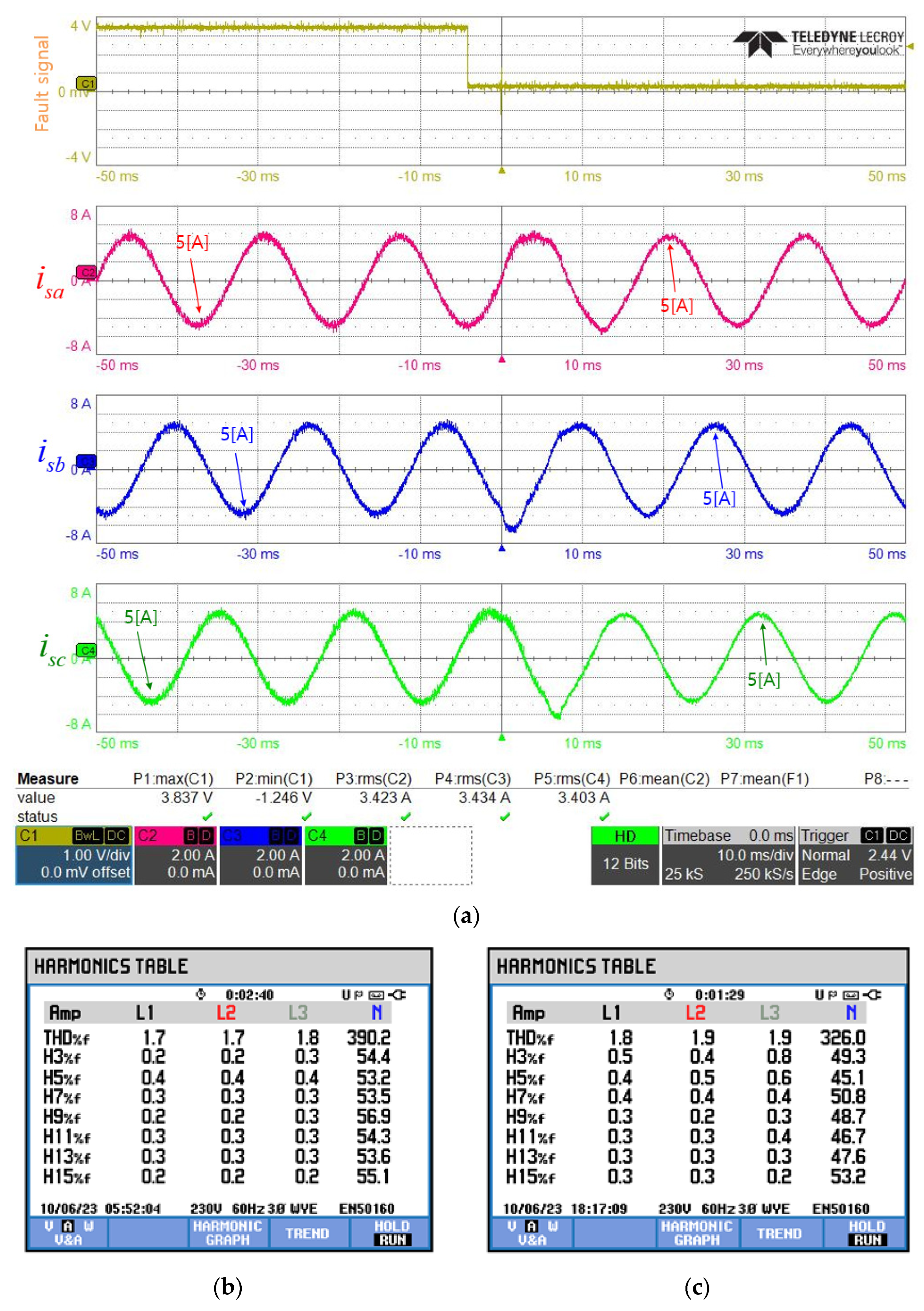
Figure 13.
Graph of current THDs measured according to load current magnitude.

Figure 14.
Graph of the averages of current THDs measured according to load current magnitude.

Table 1.
Summary of various parameters used in the simulations.
| Parameter | Unit | Value |
|---|---|---|
| [] | 400 | |
| [] | 4700 | |
| [] | 28.14 | |
| [] | 15 | |
| Fault switch | [] | S8, S11 |
| Switching frequency | [] | 20 |
Table 2.
Summary of various parameters used.
| Parameter | Unit | Value |
|---|---|---|
| ] | 400 | |
| ] | 4700 | |
| ] | 28.14 | |
| ] | 15 | |
| Switching frequency | ] | 20 |
| IGBT | [-] | SKM150GB12T4 |
| Gate driver | [-] | SKHI22BH4R |
| MCU | [-] | TMS320F28335 |
Disclaimer/Publisher’s Note: The statements, opinions and data contained in all publications are solely those of the individual author(s) and contributor(s) and not of MDPI and/or the editor(s). MDPI and/or the editor(s) disclaim responsibility for any injury to people or property resulting from any ideas, methods, instructions or products referred to in the content. |
© 2024 by the authors. Licensee MDPI, Basel, Switzerland. This article is an open access article distributed under the terms and conditions of the Creative Commons Attribution (CC BY) license (https://creativecommons.org/licenses/by/4.0/).
Share and Cite
MDPI and ACS Style
Lee, H.; Kim, G.; Shon, J. Application and Verification of a Leg-Transfer Method for Three-Level Active Neutral-Point-Clamped Inverters for Railway Vehicles. Energies 2024, 17, 1967. https://doi.org/10.3390/en17081967
AMA Style
Lee H, Kim G, Shon J. Application and Verification of a Leg-Transfer Method for Three-Level Active Neutral-Point-Clamped Inverters for Railway Vehicles. Energies. 2024; 17(8):1967. https://doi.org/10.3390/en17081967
Chicago/Turabian StyleLee, Hyunjae, Gildong Kim, and Jingeun Shon. 2024. "Application and Verification of a Leg-Transfer Method for Three-Level Active Neutral-Point-Clamped Inverters for Railway Vehicles" Energies 17, no. 8: 1967. https://doi.org/10.3390/en17081967
Note that from the first issue of 2016, this journal uses article numbers instead of page numbers. See further details here.