

Development of a Genetic Algorithm-Based Control Strategy for Fuel Consumption Optimization in a Mild Hybrid Electrified Vehicle’s Electrified Propulsion System
 ,
,
Abstract
:1. Introduction
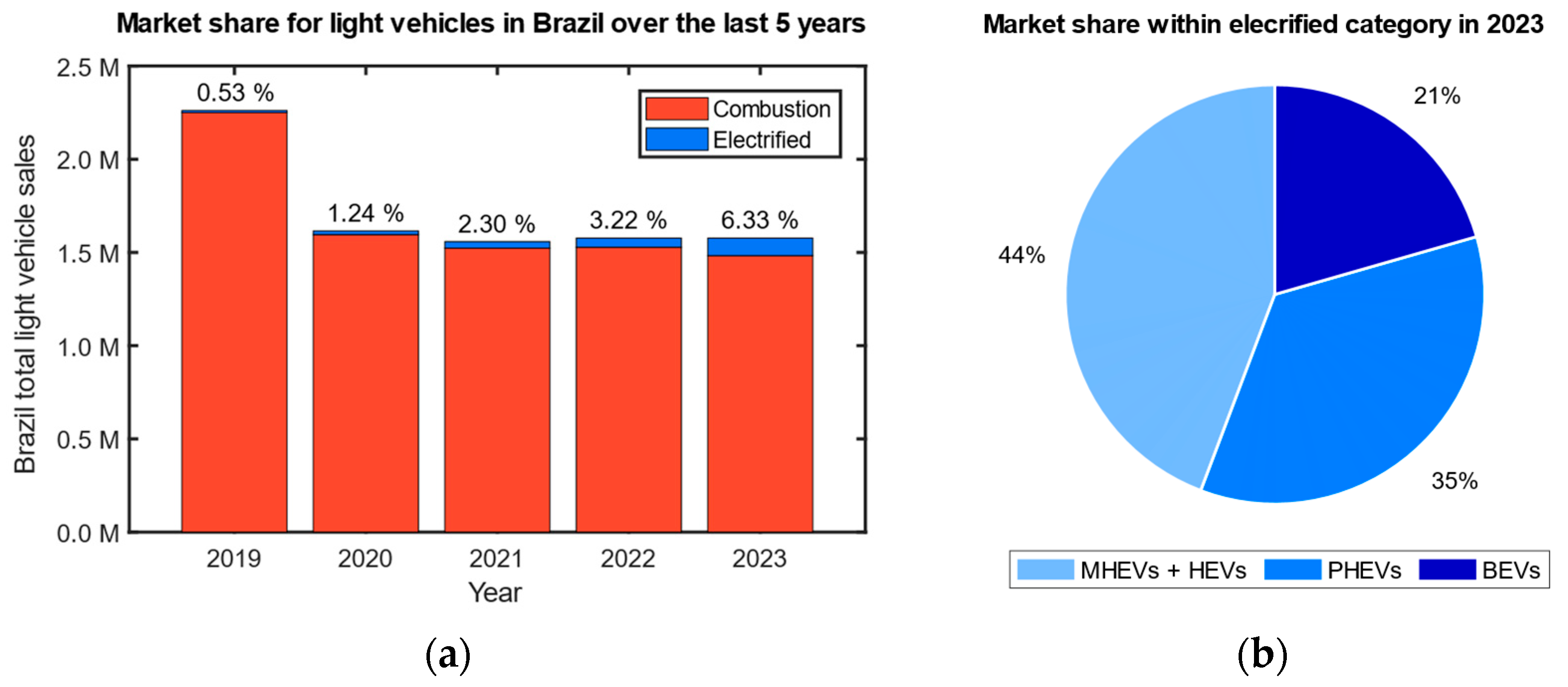
1.1. The Electrification Path
1.2. Challenges in the Control Strategy
1.3. Purpose of This Research
- Virtualization: Data-based hardware (engine and e-motors) modeling and model-based control development, through acquisition of experimental hardware data.
- Tuning Automation: The use of optimization algorithms to iterate and tune the controller parameters. (e.g., GA and other optimization algorithms) [13].
1.4. State-of-the-Art
- Integration of Virtualization and Tuning Automation: While the literature review primarily focuses on discussing existing energy management strategies and optimization techniques, this proposal combines the following two concepts: virtualization and tuning automation. Virtualization involves data-based hardware modeling and model-based control development, while tuning automation utilizes optimization algorithms to iterate and tune controller parameters.
- Development of a genetic algorithm for Automatic Tuning: This paper introduces the development of a genetic algorithm (GA) to serve as an automatic tuner for calibrating the torque split and gear engagement in the MHEV. Unlike the literature review, which discussed the application of GAs in optimizing energy management strategies, this proposal specifically focuses on using a GA to fine-tune controller parameters for optimal fuel consumption. Additionally, this paper mentions referencing other optimization algorithms used for similar purposes, indicating a broader exploration of optimization techniques beyond GAs.
2. System Description and Modeling
2.1. Powertrain Architecture
- (1)
- Engine OFF: Vehicle is at standby, both ICE and BSG are OFF.
- (2)
- Engine Stop and Start (ESS): When the powertrain controller identifies enabling conditions adequate for an engine stop, for example in a traffic jam or when waiting for a traffic light, the engine is stalled (with -BSG help) and cranked again (with +BSG help), once a driver request or vehicle request (including critically low battery levels, system failure, etc.) is detected by the powertrain controllers.
- (3)
- e-Assist: When the torque requested by the driver is provided by both ICE and BSG (+ICE, +BSG).
- (4)
- ICE only: When the torque requested by the driver is provided only by the ICE (+ICE).
- (5)
- Generator mode: When the torque requested by the driver is fully provided by the ICE and, in addition to that, some torque is consumed by the BSG, which is working as a generator to charge the vehicle batteries (+ICE, -BSG).
- (6)
- e-Braking: When the braking torque requested by the driver is fully provided by the BSG, which is acting as a generator (-BSG).
- (7)
- Aggressive Braking: When the BSG is not capable of provide the total amount of braking torque being requested by the driver and the mechanical brakes are also engaged.
2.2. Vehicle Specification
2.3. Simulink Model: Architecture and Software Components
- (1)
- Drive Cycle Source: Provides the Speed profile. For this work, the HWFET (Highway Fuel Economy Test) and the first 765 s of FTP-75 (Federal Test Procedure at 75° F) were used, both of which are used for validation on light-duty vehicles with the purpose of simulating Highway (HWFET) and City (FTP-75) conditions, as in Figure 4.
- (2)
- Vehicle Dynamics model: Calculates the force demand at wheel domain (1) to maintain the speed profile from the drive cycle. The calculation is based on Aerodynamic Drag (2), Road Slope (3), Rolling Resistance (4), and Inertial (5) forces.
- (3)
- Driveline Model: Converts the force demand at the wheel domain to the flywheel domain, based on the following transmission characteristics: gear ratios, transmission efficiency, and clutch operation. The purpose of Figure 5a is to validate the Simulink model of the vehicle by comparing the operating point graph (Veh. Speed × Force) with dynamometer data acquired from a vehicle with similar architecture and characteristics, by obtaining a close match between the two curves, whereby it is possible to say if the virtualized vehicle model in fact reflects the vehicle which it is trying to represent. The dynamometer data are from the Honda Accord, acquired from [24].
- (4)
- Arbitrator: This software component uses a genetic algorithm (GA) to perform the following three most important functions of the model, aiming to minimize fuel consumption:
- Torque Split Ratio Determination: Receive the total torque demand at the flywheel from the driveline model and calculate, using a genetic algorithm (GA), the Torque Split Ratio (how the torque demand at the flywheel is delivered between ICE and BSG) at every timestep of the drive cycle.
- Gear Selection: Select the gear engaged.
- Brake Actuation Split: Calculates how the braking actuation should be delivered between mechanical brakes and BSG (alternator mode).
- (5)
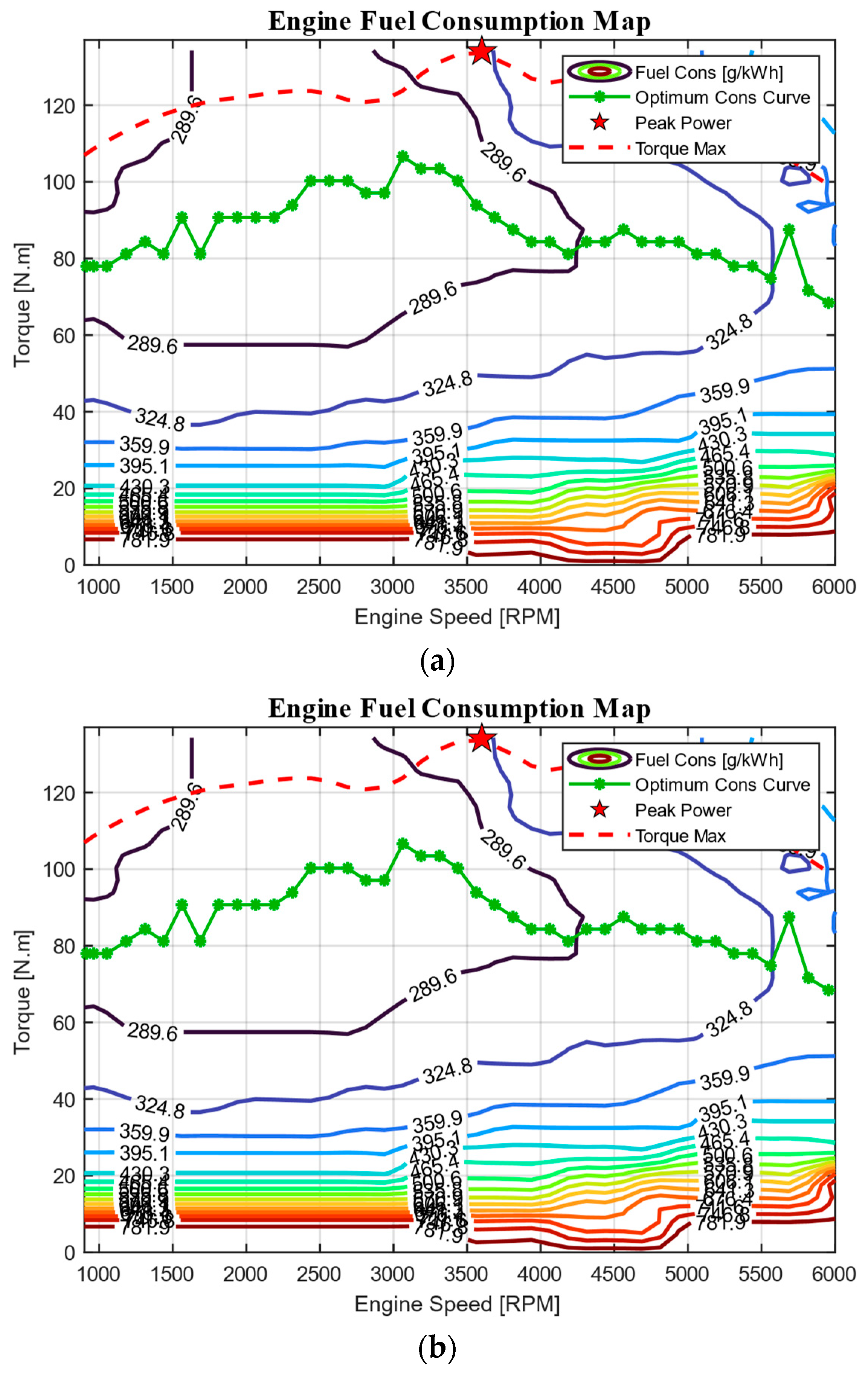
- Engine and BSG Model: Figure 6 displays the efficiency maps for both ICE and BSG. These are data-based models of the actuators (virtualization concept) and represent what kind of response, in terms of energy consumption (Fuel or Electrical), the actuator would deliver for a given (Torque and Speed) request.
- Figure 6a displays the engine map, which is a contour plot (2D visualization of a surface) for the fuel consumption, with some other valuable additions such as the Torque Max (red dashed line), which shows the engine torque constrain at each speed. The Optimum Cons Curve (green solid line with dots) displays the place of lowest consumption in the contour map.
- Similarly, Figure 6b displays the equivalent information for the BSG, the efficiency (in %, since it is an electric machine), and the Torque Max curve to display the torque constrains for BSG.
3. The Genetic Algorithm
3.1. Role of GAs as Optimization Algorithms
- It does not require smoothness of the objective function, being capable of handling continuous or discrete functions, and even a mix of both. In fact, it does not necessarily need to know the objective function, if the application can provide the outputs only for the inputs being iterated at a given moment, the algorithm would still work, e.g., an instrumented car in a dynamometer.
- It can handle unsteadiness and noise.
- It is particularly good in escaping from local minima, the ergodicity of the evolutionary operators makes it very effective at performing global search, whenever applied to a multi-peak objective function.
- It can be applied even when the search space is unknown.
- It has a remarkable balance between exploration and exploitation of the search space.
- It has great flexibility to be hybridized with domain-dependent heuristics to make a more effective implementation for a specific problem.
3.2. GA Implementation: Working Principles and Parameters
- (1)
- Population Initialization: The algorithm generates a certain amount of random binary vectors called chromosomes. Each chromosome contains all the information regarding the physical values to be optimized; in this paper, the following two parameters are contained within a single chromosome: the torque split and the gear. The first 6 bits from the chromosome carry the information related to the torque split and the last 2 bits carry the information related to the gear.
- (2)
- Evaluation: The chromosomes are converted into the physical values using a built-in MATLAB function, which converts binary to decimal. The physical value is then sent as an input to the objective function, which, in this case, is the vehicle model; however, it could be an instrumented vehicle running in a dynamometer. The objective function is responsible for providing the solutions, i.e., the instantaneous fuel and electrical consumption, as well as the battery pack SoC. With this information, the GA can calculate the fitness (represents how well the chromosome is related to the optimization goals), which is a normalized weight average of fuel consumption, instantaneous efficiency, and battery SoC.
- (3)
- Selection: There are mainly three selections, which are fixed percentages of the population, and are made based on fitness, as follows:
- The worst chromosomes on the population are deleted.
- The best chromosomes are allocated on the elite population array.
- Only at the last iteration of the loop, the very best chromosome is selected and sent as the output for that timestep of the main simulation.
- (4)
- Crossover: Randomly selects two chromosomes from the elite population, they are cut at one point and the halves are spliced, creating two offspring; the process repeats for a calibratable number of chromosome pairs.
- (5)
- Mutation: Takes a certain number of chromosomes from the elite population and reverses the bit (0 to 1 or vice versa), as on Figure 7 both for Torque Split and gear bits.
- (6)
- Population Sum: Replace the deleted chromosomes from the population for the new ones from Crossover and Mutation operations.
3.3. GA Visualization
- (1)
- The fuel consumption map of the engine Figure 8a, which provides the instantaneous fuel consumption for any given ordered pair in the search space (Torque, Speed) within the constrain limits of the hardware (speed and torque limitations).
- (2)
- The efficiency map of the BSG Figure 8b, which provides the instantaneous efficiency for any given ordered pair in the search space (Torque, Speed) within the constrain limits of the hardware (speed and torque limitations).
4. Results and Discussion
4.1. Efficiency Maps with Operating Points
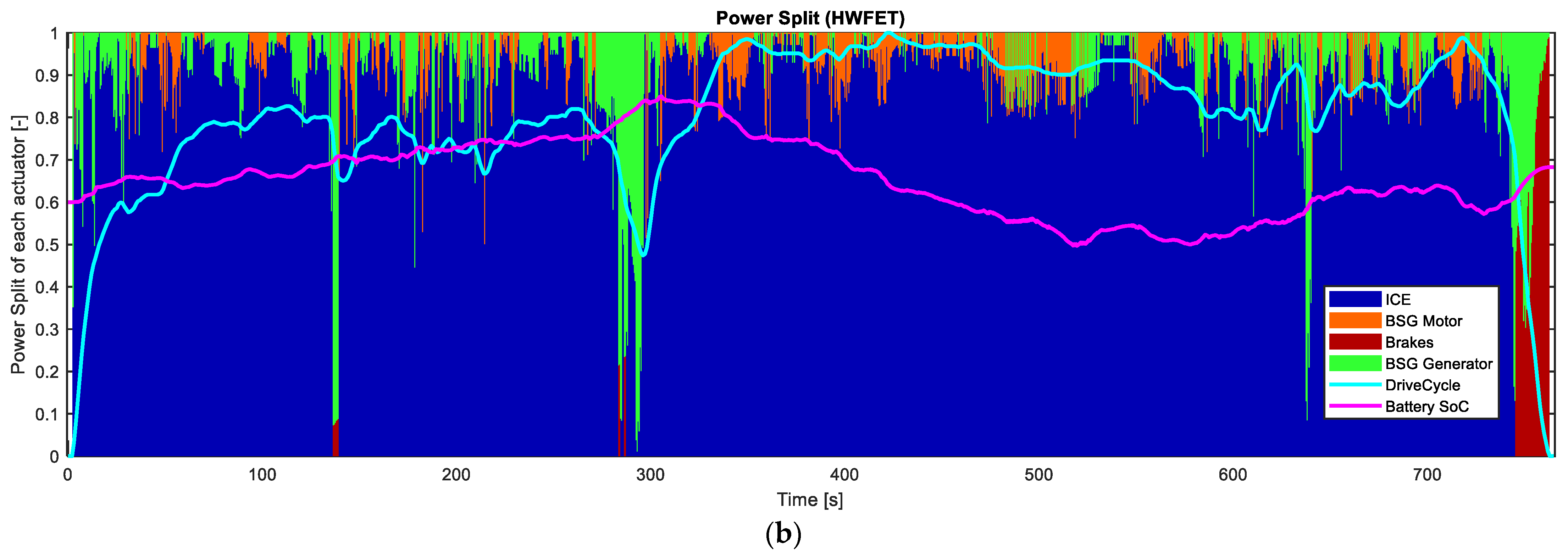
4.2. Power/Torque Split
- Positive torque/power request:
- ○
- e-Assist mode: A combination of ICE and BSG (as motor) supplies the torque/power demand.
- ○
- Generator mode: The ICE supplies all the power required for moving the vehicle and more to actuate the BSG (as generator), recharging the batteries.
- Negative torque/power request: A combination of BSG (as generator) and Brakes supplies the torque/power demand.
4.3. Drive Cycle and Operating Modes
4.4. Drive Cycle and Shift Schedule
- Gear shift cost (transient fuel consumption during gear shift event).
- Hardware durability.
- Gear shift delay.
4.5. Other Considerations
5. Conclusions
Future Development
Author Contributions
Funding
Data Availability Statement
Conflicts of Interest
References
- Davis, S.C.; Boundy, R.G. Transportation Energy Data Book, 39th ed.; No. ORNL/TM-2020/1770; Oak Ridge National Lab. (ORNL): Oak Ridge, TN, USA, 2021. [Google Scholar]
- Herzog, T. World greenhouse gas emissions in 2005. World Resour. Inst. 2009, 7, 2009. [Google Scholar]
- Chen, J.M. Carbon neutrality: Toward a sustainable future. Innovation 2021, 2, 100127. [Google Scholar] [CrossRef] [PubMed]
- Wu, G.; Zhang, X.; Dong, Z. Powertrain architectures of electrified vehicles: Review, classification and comparison. J. Frankl. Inst.-Eng. Appl. Math. 2015, 352, 425–448. [Google Scholar] [CrossRef]
- Eckert, J.J.; Barbosa, T.P.; da Silva, S.F.; Silva, F.L.; Silva, L.C.; Dedini, F.G. Electric hydraulic hybrid vehicle powertrain design and optimization-based power distribution control to extend driving range and battery life cycle. Energy Convers. Manag. 2022, 252, 115094. [Google Scholar] [CrossRef]
- Fenabrave. Anuário Fenabrave 2022: O Desempenho da Distribuição Automotiva No Brasil. 2022. Available online: https://online.fliphtml5.com/ordey/nucm/#p=1 (accessed on 7 February 2024).
- Associação Brasileira do Veículo Elétrico–ABVE. Eletrificados Iniciam 2024 Com Recorde de Vendas. 2023. Available online: https://abve.org.br/eletrificados-leves-iniciam-2024-com-novo-recorde-de-vendas-em-janeiro/ (accessed on 7 February 2024).
- Stellantis. Stellantis Announces €5.6 Billion Investment in South America, Marking the Largest Investment in the Region’s Automotive Industry [Press Release]. Available online: https://www.stellantis.com/en/news/press-releases/2024/march/stellantis-announces-5-6-billion-investment-in-south-america-marking-the-largest-investment-in-the-region-s-automotive-industry (accessed on 6 March 2024).
- Volkswagen. Volkswagen Brand Invests one Billion Euros for Growth in South America [Press Release]. Available online: https://www.volkswagen-newsroom.com/en/press-releases/volkswagen-brand-invests-one-billion-euros-for-growth-in-south-america-17431 (accessed on 7 February 2024).
- Júnior, A.N. Developing the EV Market in Brazil. Brazilian Electric Vehicle Association–ABVE. 2007. Available online: http://www.inee.org.br/down_loads/veh/developingtheevmarketinbrazil.pdf (accessed on 7 February 2024).
- Zhou, S.; Walker, P.; Wu, J.; Zhang, N. Power on gear shift control strategy design for a parallel hydraulic hybrid vehicle. Mech. Syst. Signal Process. 2021, 159, 107798. [Google Scholar] [CrossRef]
- Saiteja, P.; Ashok, B. Critical review on structural architecture, energy control strategies and development process towards optimal energy management in hybrid vehicles. Renew. Sustain. Energy Rev. 2022, 157, 112038. [Google Scholar] [CrossRef]
- Wahab, A.; Nadhir, M.; Nefti-Meziani, S.; Atyabi, A. A comprehensive review of swarm optimization algorithms. PLoS ONE 2015, 10, e0122827. [Google Scholar] [CrossRef] [PubMed]
- Xu, N.; Kong, Y.; Chu, L.; Ju, H.; Yang, Z.; Xu, Z.; Xu, Z. Towards a smarter energy management system for hybrid vehicles: A comprehensive review of control strategies. Appl. Sci. 2019, 9, 2026. [Google Scholar] [CrossRef]
- Jalil, N.; Kheir, N.A.; Salman, M. A rule-based energy management strategy for a series hybrid vehicle. In Proceedings of the 1997 American Control Conference (Cat. No. 97CH36041), Albuquerque, NM, USA, 4–6 June 1997; IEEE: Piscattway, NJ, USA, 1997; Volume 1. [Google Scholar]
- Lü, X.; Wu, Y.; Lian, J.; Zhang, Y.; Chen, C.; Wang, P.; Meng, L. Energy management of hybrid electric vehicles: A review of energy optimization of fuel cell hybrid power system based on genetic algorithm. Energy Convers. Manag. 2020, 205, 112474. [Google Scholar] [CrossRef]
- Denis, N.; Dubois, M.R.; Trovao, J.P.F.; Desrochers, A. Power split strategy optimization of a plug-in parallel hybrid electric vehicle. IEEE Trans. Veh. Technol. 2017, 67, 315–326. [Google Scholar] [CrossRef]
- Chen, Z.; Mi, C.C.; Xiong, R.; Xu, J.; You, C. Energy management of a power-split plug-in hybrid electric vehicle based on genetic algorithm and quadratic programming. J. Power Sources 2014, 248, 416–426. [Google Scholar] [CrossRef]
- Ahmadi, S.; Bathaee, S.M.T. Multi-objective genetic optimization of the fuel cell hybrid vehicle supervisory system: Fuzzy logic and operating mode control strategies. Int. J. Hydrogen Energy 2015, 40, 12512–12521. [Google Scholar] [CrossRef]
- Li, M.; Li, M.; Han, G.; Liu, N.; Zhang, Q.; Wang, Y. Optimization analysis of the energy management strategy of the new energy hybrid 100% low-floor tramcar using a genetic algorithm. Appl. Sci. 2018, 8, 1144. [Google Scholar] [CrossRef]
- Saini, V.; Singh, S.; Nv, S.; Jain, H. Genetic algorithm-based gear shift optimization for electric vehicles. SAE Int. J. Altern. Powertrains 2016, 5, 348–356. [Google Scholar] [CrossRef]
- Chen, S.; Lequesne, B.; Henry, R.; Xue, Y.; Ronning, J. Design and testing of a belt-driven induction starter-generator. IEEE Trans. Ind. Appl. 2002, 38, 1525–1533. [Google Scholar] [CrossRef]
- Guzzella, L.; Amstutz, A. The QSS Toolbox Manual, Institute for Dynamic Systems and Control, Department of Mechanical and Process Engineering; ETH Zrich: Zrich, Switzerland, 2005; Available online: http://www.idsc.ethz.ch/research-guzzella-onder/downloads.html (accessed on 12 June 2015).
- Argonne National Laboratory. Downloadable Dynamometer Database (D3). 2024. Available online: https://www.anl.gov/taps/hybrid-electric-vehicle-testing (accessed on 3 April 2024).
- Voß, S.; Martello, S.; Osman, I.H.; Roucairol, C. (Eds.) Meta-Heuristics: Advances and Trends in Local Search Paradigms for Optimization; ACM: New York, NY, USA, 2012. [Google Scholar]
- Mirjalili, S. Genetic algorithm. In Evolutionary Algorithms and Neural Networks: Theory and Applications; Springer: Berlin/Heidelberg, Germany, 2019; pp. 43–55. [Google Scholar]
- Mitchell, M. Handbook of Genetic Algorithms (LD Davis). Artif. Intell. 1998, 100, 325–330. [Google Scholar] [CrossRef]
- Sivanandam, S.N.; Deepa, S.N.; Sivanandam, S.N.; Deepa, S.N. Genetic Algorithms; Springer: Berlin/Heidelberg, Germany, 2008. [Google Scholar]
- Kramer, O.; Kramer, O. Genetic Algorithms; Springer International Publishing: Berlin/Heidelberg, Germany, 2017. [Google Scholar]
- Holland, J.H. Genetic algorithms. Sci. Am. 1992, 267, 66–73. [Google Scholar] [CrossRef]
- Katoch, S.; Chauhan, S.S.; Kumar, V. A review on genetic algorithm: Past, present, and future. Multimed. Tools Appl. 2021, 80, 8091–8126. [Google Scholar] [CrossRef] [PubMed]
- Haj-Fraj, A.; Pfeiffer, F. Optimal control of gear shift operations in automatic transmissions. J. Frankl. Inst. 2001, 338, 371–390. [Google Scholar] [CrossRef]
- Schönknecht, A.; Babik, A.; Rill, V. Electric powertrain system design of BEV and HEV applying a multi objective optimization methodology. Transp. Res. Procedia 2016, 14, 3611–3620. [Google Scholar] [CrossRef]


| Micro HEV | Mild HEV | Full HEV | PHEV | REEV | BEV | |
|---|---|---|---|---|---|---|
| Voltage | 12 V | 48 V + | 300 V + | 300 V + | 300 V + | 400 V + |
| Elec. System Power | 1–2 kW | 3–15 kW | 15–40 kW | 40–120 kW | 120 kW + | 160 kW + |
| Battery Capacity | ~0.5 kWh | 0.4–0.8 kWh | 0.8–3 kWh | 8–20 kWh | 20 kWh + | 60–200 kWh + |
| Start–Stop | ● | ● | - | - | - | - |
| Torque Split | ● | ● | - | - | ||
| Regenerative Braking | ○ | ● | ● | ● | ● | |
| Pure Electric Driving | ○ | ● | ● | ● | ||
| External Charging | ● | ● | ● |
| Reference | Highlight of Review |
|---|---|
| [12,14] | Xu et al. present a comprehensive review of energy management control strategies for HEVs, emphasizing the need for smarter systems. The paper evaluates various controls strategies to optimize energy usage in hybrid vehicles. |
| [15] | Jalil et al. propose a rule-based energy management strategy tailored for series hybrid vehicles. The paper introduces a set of rules governing energy usage to enhance the vehicle’s performance and efficiency, through control of Power Split and battery State of Charge (SoC) management. |
| [16] | Lü and colleagues provide a review focusing on energy optimization of fuel cell hybrid power systems in hybrid electric vehicles using genetic algorithms. The paper explores how genetic algorithms can enhance energy management strategies. |
| [17] | Denis et al. employs a genetic algorithm that optimizes the power split strategy for a plug-in, three-wheeler parallel hybrid vehicle. The paper proposes a methodology to determine the optimal power distribution between the Internal Combustion Engine and the electric motor for improved efficiency. |
| [18] | Chen et al. present an energy management approach for power-split plug-in hybrid electric vehicles, integrating genetic algorithms and quadratic programming. Employment of GA to optimize power threshold for engine to turn on, based on vehicle fuel rate, SoC, and driveline power demand. |
| [19] | Ahmadi and Bathaee focus on a multi-objective genetic algorithm for off-line optimization of the supervisory system for fuel cell hybrid vehicles. The paper discusses the integration of Fuzzy Logic Control (FLC) and Operating Mode Control (OMC) strategies to achieve superior performance. |
| [20] | Li et al. analyze and optimize the energy management strategy of a new energy hybrid, 100% low-floor tramcar employing a genetic algorithm. The study aims to enhance the efficiency and sustainability of tramcar operations. |
| [11,21] | Saini et al. propose a genetic algorithm-based approach to optimize gear shifts for electric vehicles. The paper discusses how this optimization can improve vehicle performance and energy efficiency. |
| Symbol | Parameter | Value [Unit] |
|---|---|---|
| Vehicle | ||
| mv | Dry Mass | 1300 [kg] |
| Cd | Drag Coefficient | 0.32 [-] |
| Af | Vehicle Frontal Area | 2.35 [m2] |
| Crr | Rolling Resistance Coeff. | 0.016 |
| Rw | Tire Radius | 0.3 [m] |
| Transmission | ||
| Gear Ratios | 3.70, 2.22, 1.37, 1.00, 0.74 | |
| Final Gear | 2.7 | |
| ηtrans | Mechanical Efficiency | 0.97 |
| ICE | ||
| τmax,ice | Peak Torque @3600 RPM | 134 [N.m] |
| Pmax,ice | Peak Power @5000 RPM | 64.7 [kW] |
| ꞷmin,ice | Min RPM (idle) | 900 [RPM] |
| ꞷmax,ice | Max RPM (redline) | 6000 [RPM] |
| 48 V BSG | ||
| τmax,bsg | Peak Torque | ±75 [N.m] |
| Pmax,bsg | Peak Power 1 @2150 RPM | 16.9 [kW] |
| ꞷmin,bsg | Min RPM (idle) | −5700 [RPM] |
| ꞷmax,bsg | Max RPM (redline) | +5700 [RPM] |
| Rp | Pulley Ratio 2 | 1 |
| Li-Ion Battery Pack [18650 3,14S4P 4] | ||
| BV | Pack Nominal Voltage | 50.4 [V] |
| BC | Pack Capacity | 12.8 [Ah] |
| Bv,max | Cutoff Voltage (Discharge) | 38.5 [V] 2.75 [V/cell] |
| Bv,min | Cutoff Voltage (Charge) | 58.8 [V] 4.2 [V/cell] |
| Parameter | Value |
|---|---|
| Gen—Number of generations per iteration cycle. | 20 |
| Ptot—Population size. [number of chromosomes] | 18 |
| Nmut—Number of mutations per generation. | 4 |
| Ncr—Number of crossovers per generation. | 4 |
| Pelit—Elite population size. [% of total population] | 20 |
| Ntot—Number of chromosomes generated per iteration cycle until an optimal solution is found. | 170 1 |
| Nbit—Number of bits of each chromosome. | 10 2 |
| Parameter | FTP-75 1 | HWFET 1 |
|---|---|---|
| Avg. ICE fuel economy. [km/L] | 19.1 | 16.8 |
| Generator running [% cycle time] | 59.2 | 53.6 |
| SoC target deviation [%] | 28.6 | 8.52 |
| GA avg. convergence time [in generations] | 16 | 12 |
| Main simulation timestep. [s] | 0.5 | 0.5 |
| GA iteration cycle. [in generations] 2 | 20 | 20 |
| Total simulation time. [s] | 765 | 765 |
| Number of iteration cycles performed over the entire simulation. | 1530 | 1530 |
| Number of generations over the entire simulation. | 30,600 | 30,600 |
| Number of chromosomes tested over the entire simulation. | 260,100 | 260,100 |
Disclaimer/Publisher’s Note: The statements, opinions and data contained in all publications are solely those of the individual author(s) and contributor(s) and not of MDPI and/or the editor(s). MDPI and/or the editor(s) disclaim responsibility for any injury to people or property resulting from any ideas, methods, instructions or products referred to in the content. |
© 2024 by the authors. Licensee MDPI, Basel, Switzerland. This article is an open access article distributed under the terms and conditions of the Creative Commons Attribution (CC BY) license (https://creativecommons.org/licenses/by/4.0/).
Share and Cite
Filho, R.H.Q.; Ruiz, R.P.M.; Fernandes, E.d.M.; Filho, R.B.; Pimenta, F.C. Development of a Genetic Algorithm-Based Control Strategy for Fuel Consumption Optimization in a Mild Hybrid Electrified Vehicle’s Electrified Propulsion System. Energies 2024, 17, 2015. https://doi.org/10.3390/en17092015
Filho RHQ, Ruiz RPM, Fernandes EdM, Filho RB, Pimenta FC. Development of a Genetic Algorithm-Based Control Strategy for Fuel Consumption Optimization in a Mild Hybrid Electrified Vehicle’s Electrified Propulsion System. Energies. 2024; 17(9):2015. https://doi.org/10.3390/en17092015
Chicago/Turabian StyleFilho, Roberto H. Q., Rodrigo P. M. Ruiz, Eisenhawer de M. Fernandes, Rosalvo B. Filho, and Felipe C. Pimenta. 2024. "Development of a Genetic Algorithm-Based Control Strategy for Fuel Consumption Optimization in a Mild Hybrid Electrified Vehicle’s Electrified Propulsion System" Energies 17, no. 9: 2015. https://doi.org/10.3390/en17092015