1. Introduction
Nowadays, the urban pollution from ICE-powered vehicles has led legislators to actively support the adoption of the so-called “zero pollution vehicles”. In this respect, electric vehicles (EV) appear to be a reasonable short-term solution to the problems posed by mass urban mobility. Unfortunately, EVs have a rather limited operational range (low mileage between battery charges), and this restricts their possible mission. Hybrid electric vehicles (HEV) are designed to combine the advantages of electric vehicles with those of conventional vehicles. HEVs have two on-board power sources: typically, a battery pack coupled with a thermal engine. The simultaneous presence of an electric motor/generator and of a battery pack has paved the way to the practical implementation of systems capable of partially recovering the energy otherwise dissipated during braking (Kinetic Energy Recovery System, KERS) that substantially reduce fuel consumption, especially in those missions with frequent “stop-and-go” maneuvers. Currently, there are different applicative solutions, and the University of Roma 1 (UDR1) research group adopts the “Hybrid Series” (HS), where the traction is solely electric and the power produced by the thermal engine is used only to recharge the battery pack. The advantage of the series configuration is higher fuel mileage and lower emissions, due to the possibility of limiting the operation of the internal combustion engine to its peak efficiency range and to the reduced engine weight. The UDR1 Research group at the Department of Mechanical & Aeronautical Engineering of the University of Rome "Sapienza" proposes a new concept of hybrid vehicle [
1,
2,
3,
4,
5], in which the thermal engine is a suitable optimized gas turbine set. This paper reports our proposed general procedure for the preliminary design and sizing of an HS engine applied to the hybridization of a seven ton city bus.
2. Definition of the Degree of Hybridization
The mechanical power in an HS vehicle is typically supplied by one electric motor (EM), and from the vehicle traction point of view it is considered an electric vehicle. The choice of the EM is a direct function of the required performance. If otherwise, the installed electric power sources may depend on different considerations. It is possible to identify two extreme solutions: the first one is a “double electric” source, with the battery pack and thermal engine generating all electric power required by the EM (a typical example of this design philosophy is the Toyota Prius [
7], where the vehicle can operate using only the battery pack in a total electric configuration, only the ICE in the standard configuration, or together to get the best performance); the second solution can be defined as “minimal electric” source: battery pack and thermal engine simultaneously provide all electric power to the EM, but the absence of just one of these power fluxes compromises the vehicle performance (without the battery pack the vehicle does not have the sufficient power required by the traction, and without the ICE the vehicle is not able to supply energy to complete the typical mission for which it is designed). Between these two configuration there are many possible solutions, and we adopt the minimal electric source to minimize weight, volume and engine cost [
3,
4]. Therefore, once we have defined the vehicle class (the actual physical characteristics like mass, C
X,
etc.), we have chosen the driving missions of the vehicle. Successively, the maximum required electric power is fixed, then the total power source, supplied by the ICE and battery pack, is calculated. Finally we evaluate the Hybridization Degree HD (our design target), meaning the calculation of the correct ratio between the GT power and the total installed power (GT and battery pack).
3. Design Procedure, Optimal Configuration
To find the correct HD we have adopted a method based on an energy balance evaluation [
1,
2,
3,
4]. To perform a driving mission, any vehicle needs an energy supply; in a traditional ICE vehicle this energy is guaranteed by the thermal unit that delivers, instant by instant, the power for the traction. The ICE is characterized by a large power range and can be easily connected to the wheels. On the other hand, all these considerations cannot be applied to the GT set (used as a thermal power source), because it has a very limited operative range, and the connection to common vehicle wheels is practically not possible for the high rotational speed of the GT set (usually >25,000 rpm). Therefore, if a GT is used as a thermal power source, the HS engine configuration is a forced choice. This is because, in an HS vehicle, the function to follow the power request (load following operational mode), second by second, is accomplished by the battery pack. Consequently, the on-board GT unit has to avoid the battery pack discharging during the mission and simultaneously to support the pack in the generation of required power peak. This reduces the installed battery modules. We underline that in an HEV, the problem is not the same as in an ICE vehicle—to have a thermal engine that can produce the required power instantaneously—but to have a system capable to supply, instant by instant, sufficient electric stored energy to perform the next step of the mission.
To better explain this concept, it can be noticed that during the vehicle mission there are several operational phases in which the vehicle absorbs energy (acceleration), and others where it does not (deceleration or stop). The HS vehicle needs to use this second phase to recover energy to the battery.
To evaluate the number of battery modules, a statistical evaluation between energy consumption and charging phase frequency is required. For these reasons, the method used is based on an energy balance.
The optimum solution is a system where the sum of GT and KERS produced energy supplies exactly the total energy consumption, for each assigned mission. This assumption, in our code, represents the energy balance. A positive result in the calculations indicates that the battery pack SOC is higher at the end of the mission, than it was initially; obviously a negative result indicates a lower SOC. To perform the analysis, we started defining the vehicle, with the identification of typical physical characteristics: mass, frontal area, C
x, rolling resistance [
1,
4]. A second step is the definition of the characteristic environmental parameters, typically, standard values for air density and gravity acceleration. To consider the presence on board of KERS dispositive, we have defined and set some operative coefficients like breaking recovery coefficient (BRC) and minimum recovery velocity (MRV). The last operative parameter is the degree of hybridization (HD). Each operative parameter set represents a vehicle configuration. At the end of this preliminary phase, we selected several representative missions (e.g., urban routes for a city car or bus).
Finally, once all the needed data was defined, we evaluated for each mission: how much energy is required by the vehicle, how much energy can be recovered by KERS system and how much energy can be produced by the thermal source.
Thus, simply adding these results, we could compute the optimal energy balance for that particular mission, and the vehicle configuration. Our code repeats this calculation for an assigned mission varying only the vehicle operative parameter, represented by the installed GT nominal rate. The result of this calculation is a diagram that reports the energy balance as a function of the installed GT nominal power. By repeating this calculation for every possible GT power rate and mission, we have been able to create the operative diagram, and consequently, to choose the battery pack modules and the GT set .
4. Preliminary Calculation Method
The code, implemented on Matlab™ environment , calculates, second by second, the required power for traction, breaking and available to KERS, for any assigned mission and vehicle configuration [
4].
As the first calculation step, it evaluates the needed power for acceleration, deceleration, inertia, rolling resistance and aerodynamic resistance. This operation has to be repeated for every different vehicle configuration and for all selected missions, so the number of data and diagrams increase quickly.
During this procedure step, some vehicle parameters have been considered as constant and for some others a range of variability has been set (i.e., mass vehicle, KERS efficiency coefficient, etc.). The typical code analysis simulates every selected mission, considering the maximum and minimum vehicle pay load. In addition to these two options for the vehicle set up, KERS minimum and maximum efficiency is also considered, so the total combination of these variable vehicle parameters consequently generates four simulating cases for each selected mission. The second calculation step analyzes all power requests among all four cases for a chosen mission, and the maximum value of the power is considered as the vehicle total required power. The second part of the code performs the optimization of the vehicle configuration, considering a variable GT nominal power into a range within 0 kW of the maximum power request for the analyzed mission; this is repeated for each configuration combination. This means that we analyze the mission for a variable degree of hybridization in a range of 0–100%.
In this phase, the code applies a simple on-off logic, setting the GT range to 70–100% of the nominal power rate. When the mission power request is higher than 70% of nominal GT power, it is switched on and immediately reaches the nominal power; on the contrary, when the mission request is lower than 70%, the turbine is switched off. During this phase, all excess power is available for the battery recharging operation.
The choice to adopt an “on-off” logic derives from experimental considerations and by the experience in the HS vehicle design, especially in the urban cycles, where it is mandatory to minimize the “working time” of the GT device. The adopted electronic logic (VMU) has been partially described in a previous paper of the authors and it is not a topic of this new study [
3,
4].
The result of this calculation step is a diagram that represents the mission energy balance as a function of the installed GT power. For each mission, this operation is repeated for every vehicle configuration (four), meaning four supplementary energy balance diagrams.
Comparing all these diagrams, it is possible to define the optimal installed GT nominal power rate to successfully complete all assigned missions, and consequently, when we define the power of the installed EM, we are establishing the number of battery modules needed to complete the HS engine, and defining the hybridization degree HD for the studied HS engine.
5. Selection Test Cases
In this paper, the study reports analyze the possible hybridization of a mini bus of about 7 ton. Vehicle physical characteristics are provided by customer (city transportation agency: C
X 0.75; frontal area 4.62 m
2; rolling resistance 0.018). We set an operative breaking recovery coefficient of 60–80%, in addition we considered mass variability (passengers payload) in a range of 6–8 tons. The combination of these variables supplies four possible vehicle base configurations for the energy balance analysis (
Table 1). Other parameters we set are: constant C
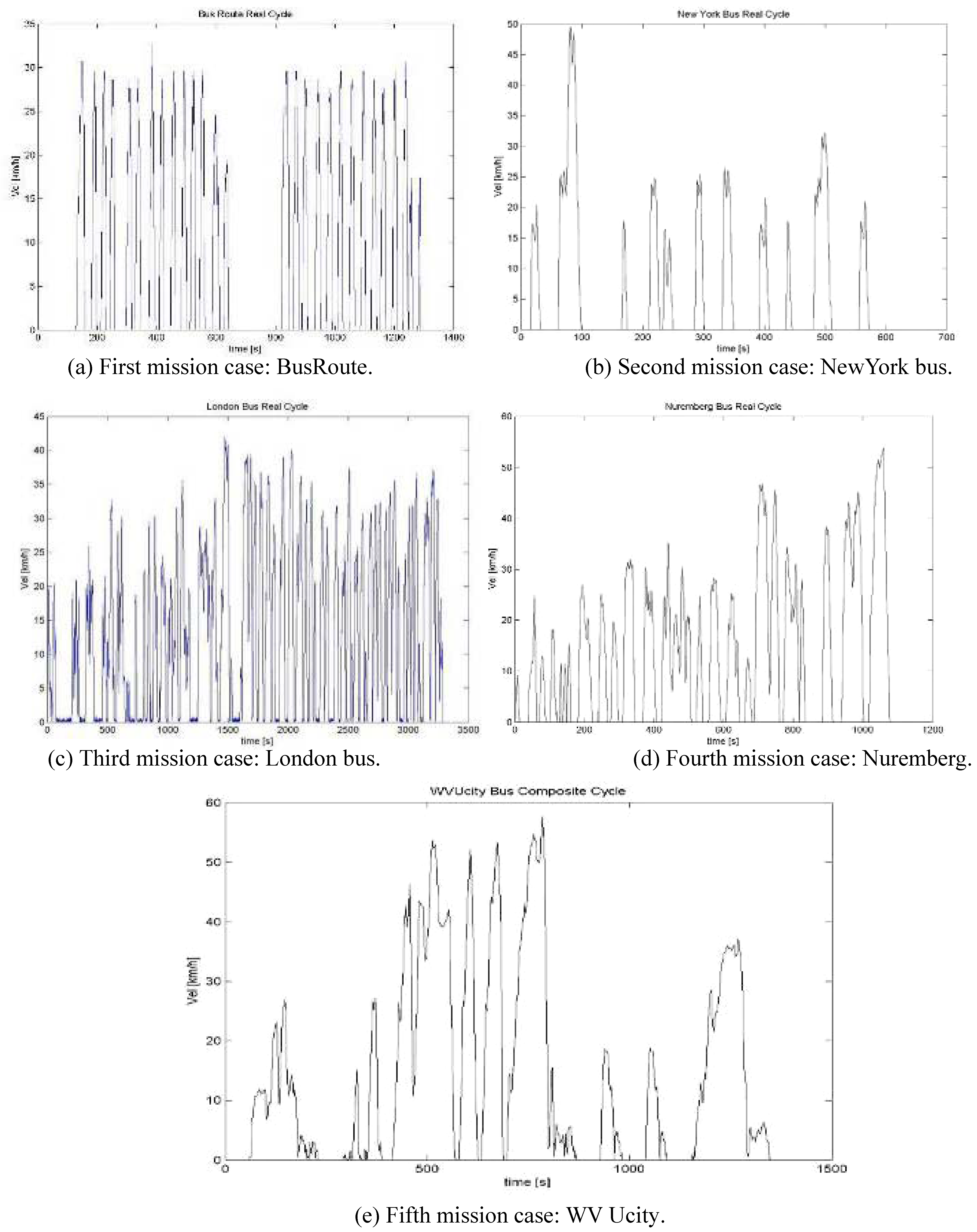
X, the bus frontal area, rolling resistant coefficient, air density, gravity acceleration and minimum velocity available for breaking recovery. We chose to apply the analysis to five missions, some of which are actual bus routes and some that are a combination of these bus routes. Note that a typical case mission speed/time diagram consists of a second by second report of the required vehicle speed, or otherwise the required power to maintain in each instant the set rate (see Figures below).
Figure 1.
Speed/time diagram of bus route mission cases.
Figure 1.
Speed/time diagram of bus route mission cases.
The common characteristics of this type of mission are the high frequency of accelerations and decelerations typically of urban traffic. For other aspects, like maximum speed (V
max), average speed (V
avg), max acceleration (+a), max deceleration (–a), stop-and-go frequency (s/n) and stop-and-go medium distance (n/km), selected missions are quite different from one another, as shown in
Table 1.
Table 1.
Comparison of bus route mission characteristics.
Table 1.
Comparison of bus route mission characteristics.
| Vavg [Km/h] | Vmax [Km/h] | n/km | s/n | +a [m/s2] | –a [m/s2] |
|---|
| NewYork bus | 5.9 | 49.6 | 11 | 54.5 | 2.8 | 2.0 |
| BusRoute | 7.2 | 32.7 | 10.7 | 46 | 1.7 | 2.3 |
| London bus | 13.3 | 41.9 | 6.5 | 41.6 | 1.3 | 1.6 |
| WV Ucity | 13.6 | 57.6 | 2.6 | 100.5 | 0.3 | 0.4 |
| Nuremberg | 14.3 | 53.7 | 5.5 | 45.1 | 0.58 | 0.55 |
6. Case Analysis First Calculation Step
Once thevehicle and environmental characteristics were defined, we set a configuration, and for each mission and vehicle configuration analyzed all power fluxes required by traction, breaking and the power available for KERS.
Table 2 summarizes all these considerations.
Table 2.
Four vehicle configuration.
Table 2.
Four vehicle configuration.
| Configuration | Mass [t] | BRC |
|---|
| A | 6 | 0.8 |
| B | 8 | 0.6 |
| C | 6 | 0.6 |
| D | 8 | 0.8 |
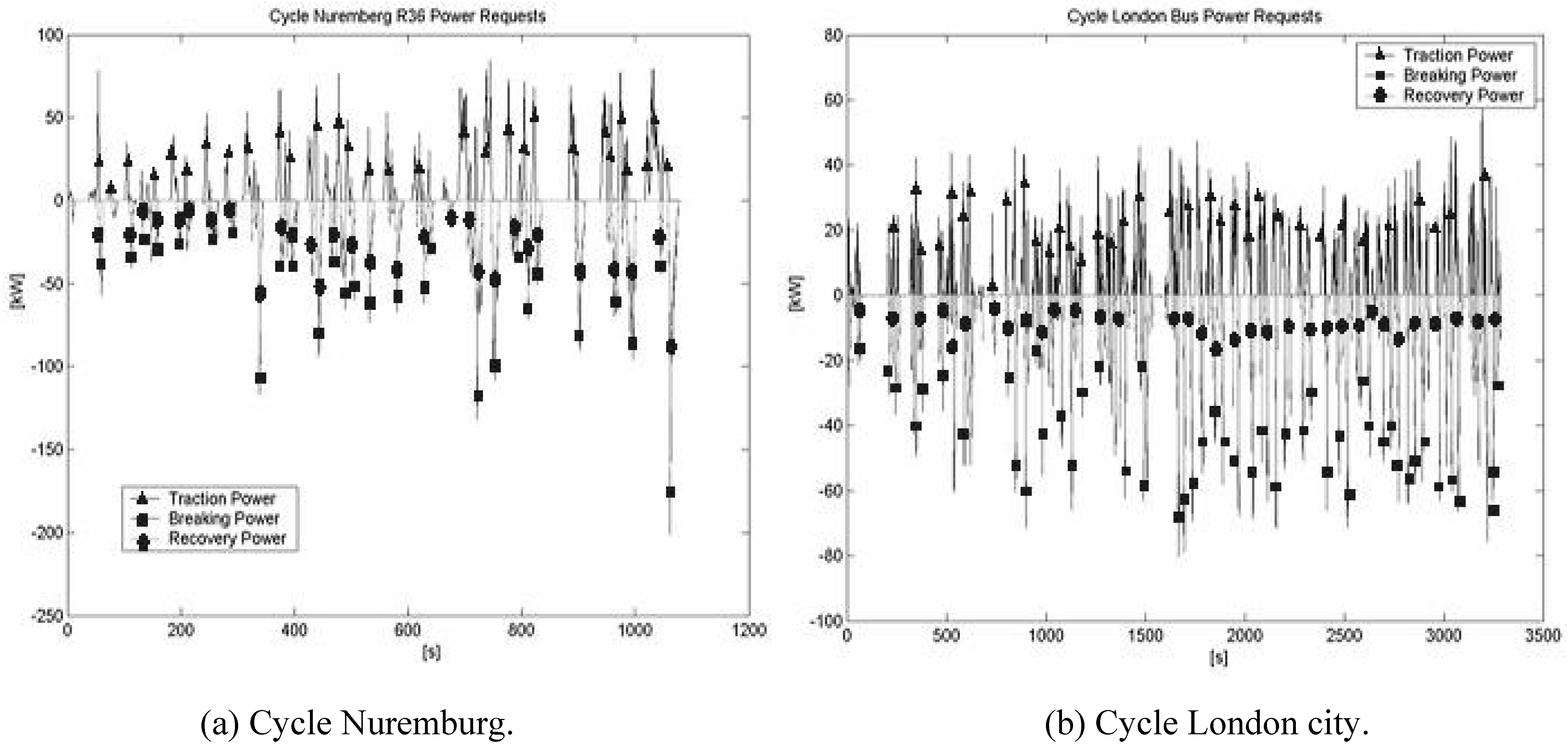
This second code, also implemented on Matlab™ environment, analyzes the interaction between vehicle and mission, computing the power request, and supplies a power/time diagram, as shown in the following figures (
Figure 2,
Figure 3 and
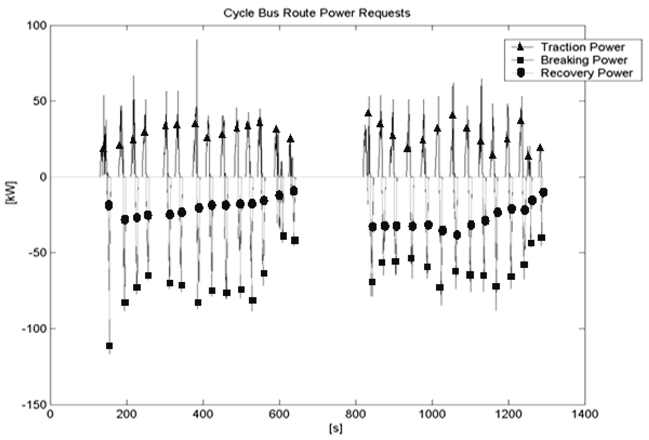
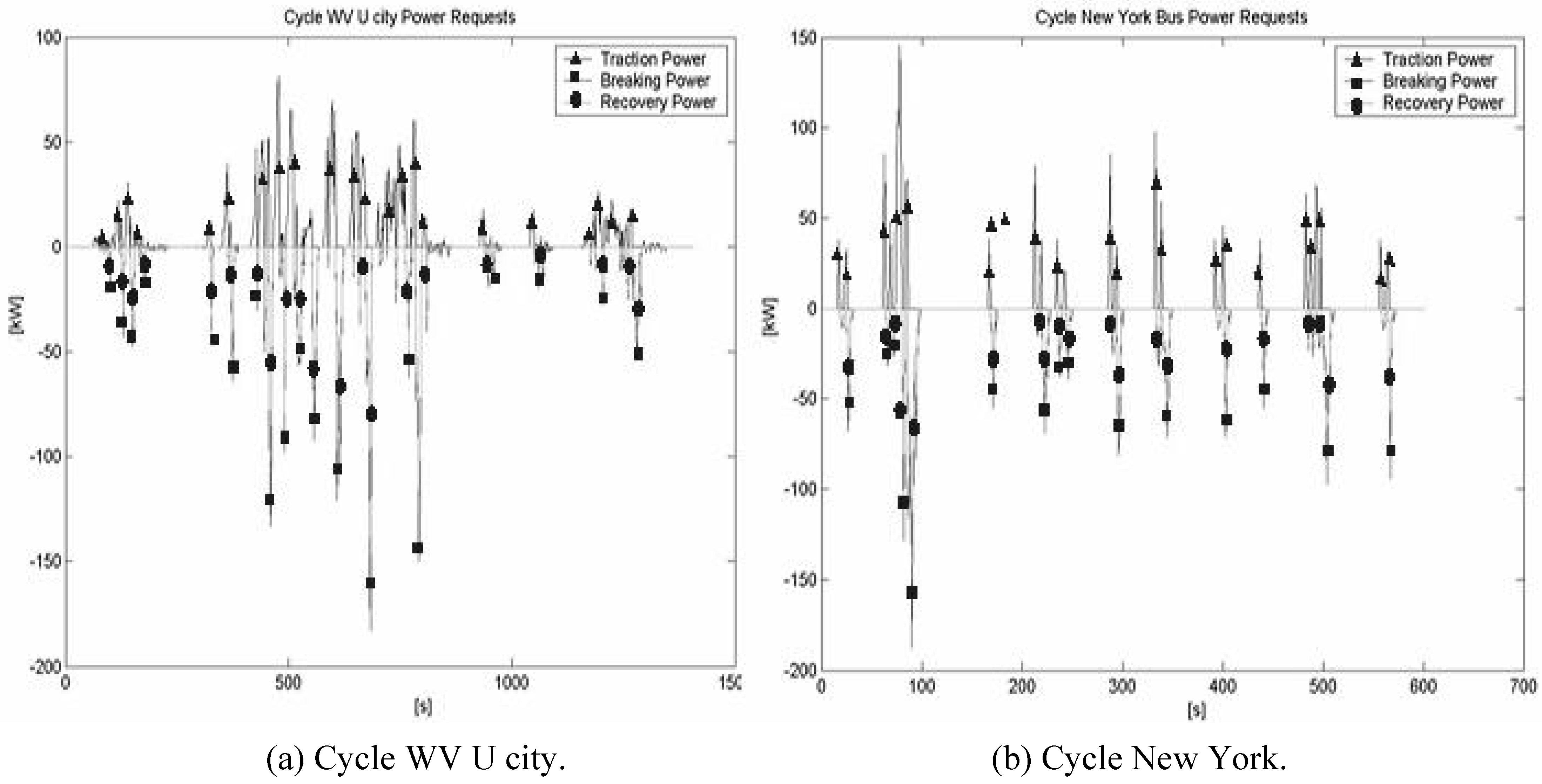
Figure 4). These diagrams show the power request of the first configuration for each considered mission. Power analysis diagrams of the other cases are substantially the same, the differences are in the values of the power peak, but since the aspect of the diagrams case by case are the same we don’t report them here, we only form synthesis reasons. In these graphs, positive values represent the traction power required by the electric motor, negative values (square dot line) are required by the breaking system to ensure deceleration, dot negative lines show the energy potentially available for KERS. In our simulations, we have assumed that recoverable power from the mission is a fixed percentage of the breaking power (BRC).
7. Case Analysis Second Calculation Step
In the second step of calculation, we used the calculated power request as input for our second implemented code. This program simulates the mission energy flux management, comparing traction, breaking, and KERS. Thanks to the software, we have been able to investigate the energy exchanges between each main component of the HS engine: electric motor, battery pack and electric generator.
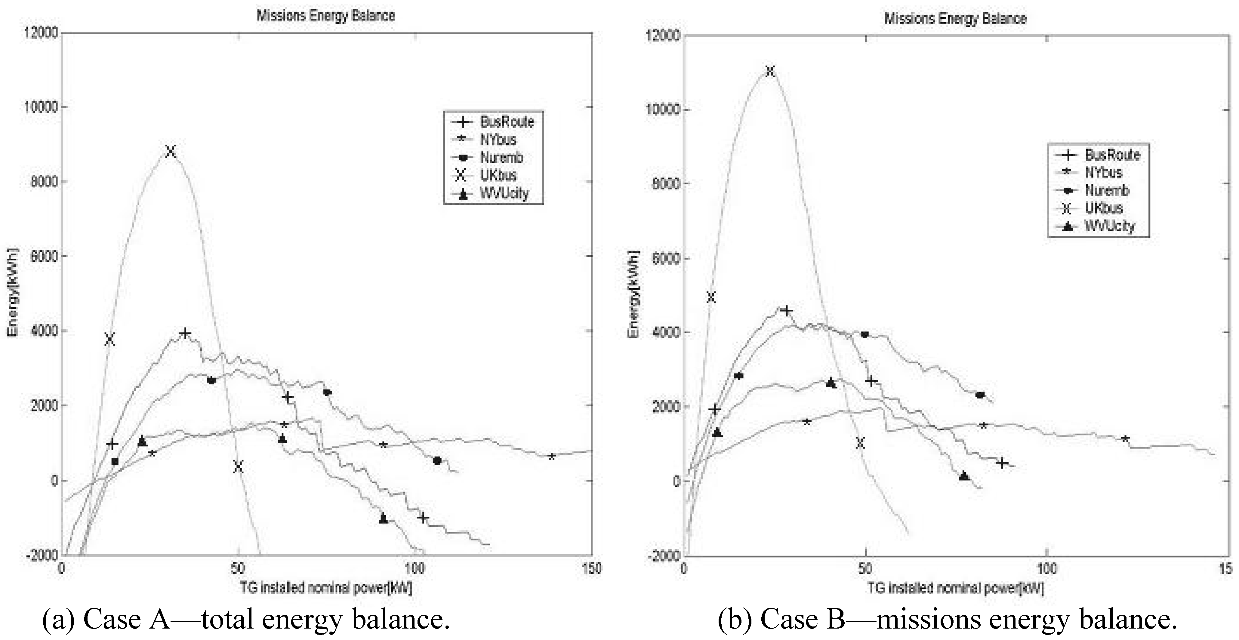
As mentioned before, this operation is repeated, considering a variable GT nominal power into a range within 0 kW to the maximum power request for the analyzed mission, for each vehicle configuration (from A to D) and for each mission (five bus routes as reported in Table A). The results of this procedure are diagrams that, for each assigned case, represent the “mission global energy balance” / “installed GT power” ratio, as seen in
Figure 5.
Figure 2.
Case A power analysis (power/time diagrams).
Figure 2.
Case A power analysis (power/time diagrams).
Figure 3.
Case A power analysis.
Figure 3.
Case A power analysis.
Figure 4.
Case A power analysis (Cycle Bus route).
Figure 4.
Case A power analysis (Cycle Bus route).
Figure 5.
Missions energy balance.
Figure 5.
Missions energy balance.
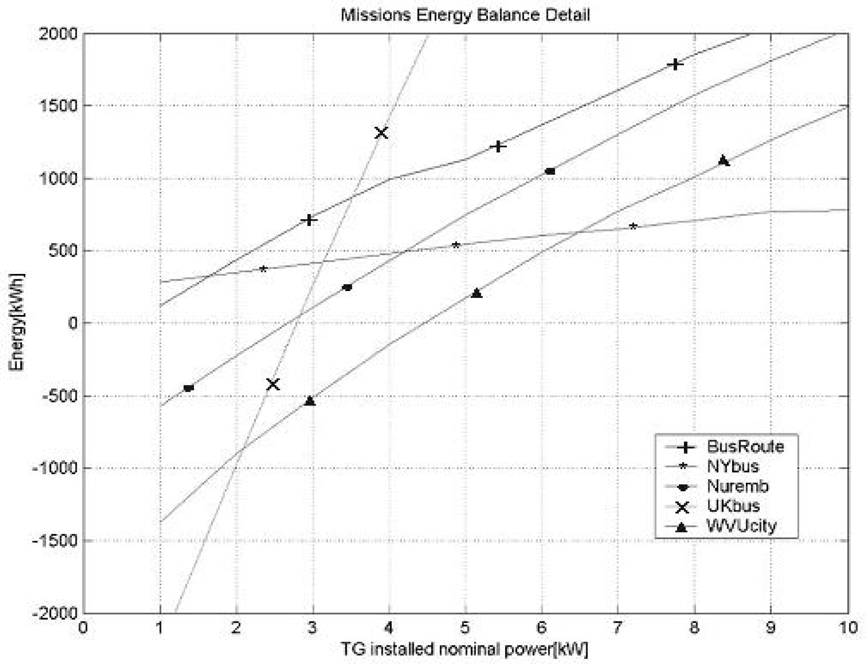
In
Figure 6 below, a detail near zero value is useful for our study and allows us to investigate the energy balance.
This method indicates that for each group of similar missions and for an assigned vehicle configuration, an optimized GT power close to zero exists, able to ensure a good energy balance for each mission. Note that the optimized GT power is common for all the studied missions and vehicle configurations, so the HD varies with the maximum power requested by each mission.
Figure 6.
Missions energy balance detail.
Figure 6.
Missions energy balance detail.
8. Results Analysis
All diagrams are directly dependent on the VMU logic applied in the second step code; meaning that we operate in a conservative mode.
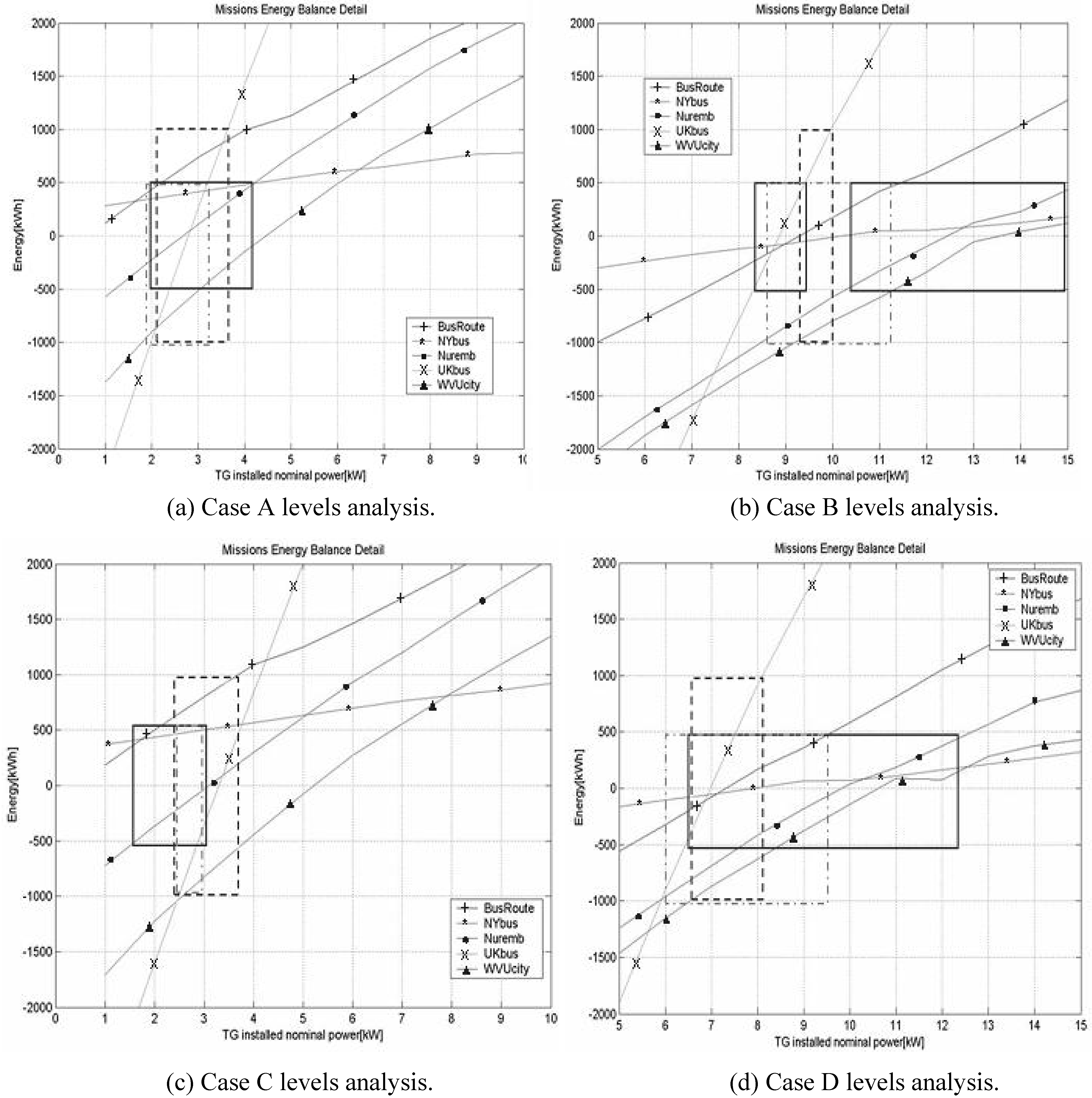
Furthermore, tolerability ranges, as +/– acceptable energy unbalance, have been defined. Assuming that the actual VMU control logic [
4] is capable of compensating this unbalancing energy calculation, three levels of energy unbalance have been chosen. We define an assigned energy unbalance by fixing a value for admissible energy excess and for an admissible energy lack; in addition we choose for each level the minimum number of curves that must be included.
Successively, on the energy balance diagrams, we investigate which GT nominal power satisfies each level of energy unbalance conditions. This operation is represented on the diagrams in
Figure 7 with square of different type lines.
The chosen energy unbalance levels are the following:
+/–0.5 MWh with at least three curves included, continuous square dot line.
+/–1 MWh with all curves included, dashes square line.
+0.5 MWh and –1 MWh with at least four curves included, square dot line.
These choices are based in part on our experience into HS vehicle design and in part on the consideration that the VMU applied a simple on/off logic for this calculation [
3,
4]. Furthermore, the missions are urban ones; thus it is reasonable to assume that it is easier to recover from negative energy unbalances than positive ones, because during the mission, there are several seconds while the vehicle is stationary or the power request is low.
Figure 7.
Levels analysis.
Figure 7.
Levels analysis.
Above all, the program sensitivity to mass variation can be noticed. Fixing a high energy recovery coefficient, represented by the comparison between the first and fourth cases, the simulation remarks a low installed GT power variation for a balanced energy supply. On the other hand, in the case of low energy recovery efficiency, showed by the comparison between the second and third cases, the GT installed power variation increases clearly. The second observation regards the system sensitivity to BRC variation. The comparison between the first and third cases, minimum payload condition, remarks a large power variation between each energy level; we achieve the same result when comparing the fourth and second cases (maximum payload), where the installed power variability between levels is very wide. Therefore, the first preliminary conclusion is that for this type of vehicle, the main important parameter is the KERS efficiency coefficient. For these reasons all our efforts have been to develop a code that indicates the optimal solution, by the HD calculation.
9. Conclusions
The energy balance analysis suggests installing a thermal power source (GT set) of about 2.5–3 kW on this type of vehicle, only considering the energy management directly connected to vehicle mobility. On customer indication, this mini bus has energy consumption for auxiliaries, like air conditioner, heater, cooler, hydraulic pump, air suspension, breaking servo and lights, of about 6.5–7.5 kW. We finally fixed the power of installed GT generators at about 10 kW. As customer specification, the EM power peak is of 60 kW. Consequently, the battery packs power size must be about 57–58 kW (that means 50 kg of on board pack), based on vehicle EM power peak. This mean that the HD computed and consequently suggested for this vehicle is about 16%. As mentioned before, the resulting HS engine makes this vehicle
de facto an electric one with a little thermal power charge. We are confident that this design method allows one to define fundamental vehicle characteristics like installed power generation source and the number of batteries modules, simply starting from physical parameters and a set of typical mission. We have already applied this method to the hybridization of car and train [
1,
2,
3,
4,
5], and based on our experience, the result is that any vehicle can be converted into a hybrid one with evident advantages in terms of emission and fuel consumption resulting from the decreasing thermal power source in favor of batteries power.


