1. Introduction
Research and development of electric vehicles (EVs) has received increasing attention from governments, industry, and public around the world due to the growing concerns about global warming, fossil fuel shortage, as well as passenger vehicle safety. Great technical progress has been made in the areas of system structure and key component development for electric vehicles in recent years, but there is still a performance gap between electric vehicles and conventional vehicles with respect to driving range, energy-saving and powertrain efficiency and safety.
For a conventional vehicle, a significant amount of energy is consumed in urban driving cycles by braking [
1,
2]. To improve the performance of electric vehicles, the regenerative braking system has been developed. It utilizes the electric motor, providing negative torque to the driven wheels and converting kinetic energy to electrical energy for recharging the battery or power supply. The dissipation of kinetic energy during braking, by an electric or hybrid vehicle can be recovered advantageously by controlling the power electronics for total energy management onboard the vehicle. Therefore, regenerative braking is an efficient technology to improve the efficiency of electric vehicles. Research indicates that substantial energy savings are in fact achievable, from 8% to as much as 25% of the total energy use of the vehicle, depending on the driving cycle and its control strategy [
3,
4]. Particularly, this additional energy recycling can be achieved without adding of any extra components. In addition to their energy regeneration benefits, motor brakes are superior to hydraulic brakes in their accuracy, quick response and ease of measurement.
Various attempts to satisfy the control performance needs for regenerative braking have been presented in the literature, such as rule based strategies [
5,
6], fuzzy control strategies [
7,
8,
9,
10], H
∞ control [
11,
12,
13,
14,
15], and neural network approaches [
16,
17]. However, a regenerative braking system is an uncertainty system with nonlinear parameter perturbation and serious external disturbances. These classical control methods are ineffective to guarantee the performance control. What’s more, these studies have mainly focused on improving the energy recovery performance based on common factors. Hardly any studies on the structure of drive systems have been done from the standpoint of vehicle driving safety and riding comfort.
The safety and riding comfort of vehicles are strongly influenced by the braking performance since various phenomena uncontrollable by the driver’s pedal operations occur when braking [
18,
19]. In regenerative braking strategy (RBS) design, the objectives of safety, reliability and easy application are the most important factors that should be considered.
Consequently, a fuzzy logic based braking control strategy integrated with series regenerative braking for electric vehicles is developed in this paper to advance the level of energy-savings, as well as vehicle driving safety. Under normal braking conditions, the strategy can achieve almost optimal regenerative efficiency. It can also prevent wheel locking and slip phenomena from occurring at the time of braking by distributing suitable braking torque to the front and rear wheels according to running conditions. Through the experiment results, we can verify the effectiveness of the control strategy in ensuring braking safety and stability and improving energy efficiency.
The remainder of this paper is organized as follows:
Section 2 introduces the prototype EV and the structure of the composite braking system used for evaluating the RBS.
Section 3 goes through the principle of brake force distribution between front and rear wheels. The distribution between regenerative brake force and friction brake force and fuzzy RBS design are implemented in
Section 4.
Section 5 provides the experimental results and analysis. Finally, conclusions are given in
Section 6.
2. Structure of “LF620” Prototype EV
The prototype EV used in this study is the “LF620” EV, developed by the Shenzhen Institutes of Advanced Technology, Chinese Academy of Science (SIAT-CAS). It has passed the test of National Passenger Car Quality Supervision and Inspection Center. It had served during the World Expo 2010 Shanghai as a police patrol car. The “LF620” is a front-wheel drive electric vehicle. Its powertrain integrates a permanent magnetic synchronic motor (PMSM), lithium-ion battery, and an automatic/manual transmission system. The motor is directly linked to the input of the transmission. A photo and the important parameters of this vehicle are given in
Figure 1 and
Table 1, respectively.
Figure 1.
LF620 prototype EV.
Figure 1.
LF620 prototype EV.
Table 1.
Vehicle Parameters.
Table 1.
Vehicle Parameters.
| Dimensions (mm) | 4550 × 1705 × 1495 |
| Curb Weight (kg) | 1550 |
| Gearbox Ratio (Fixed ratio) | 1.895 |
| Main Difference | 4.308 |
| PMSM | Power (kM) | 20/40 |
| Torque (N m) | 75/150 |
| Lithium-ion Battery | Voltage (V) | 320 |
| Capacity (Ah) | 80 |
In using regenerative braking, a significant change is made to the architecture of the vehicle braking system [
20,
21,
22]. EVs employ both a conventional hydraulic braking system and a regenerative braking system. Despite of the advantages of motor brakes, the hydraulic brake unit is still reserved in consideration of possible failure of the electrical system.
There are two ways to coordinate the regenerative torque of the motor and the friction torque of the hydraulic unit: parallel and series [
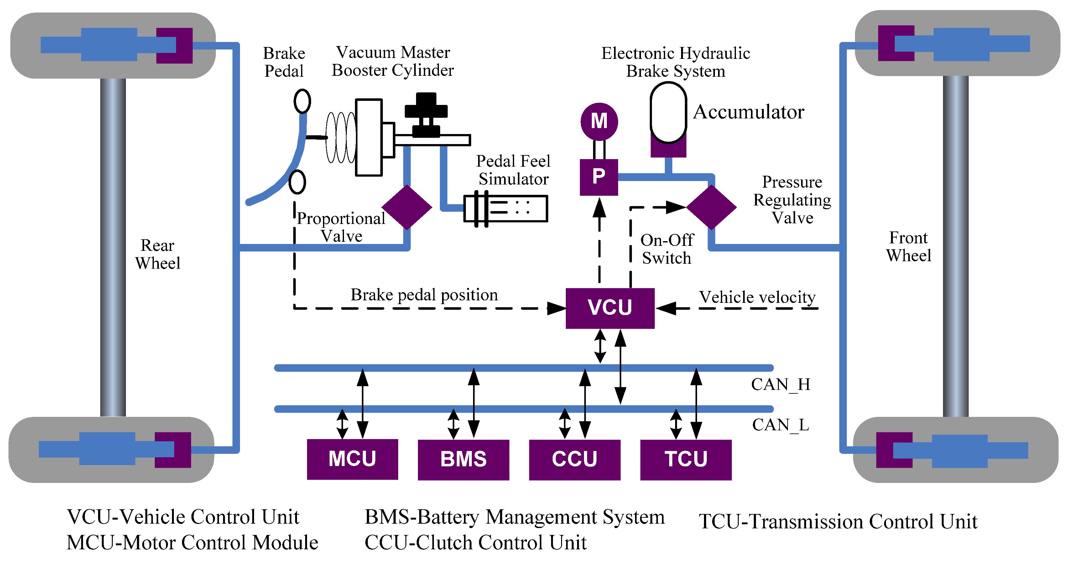
20]. In parallel braking, the regenerative torque of the motor is exerted on the driving axle directly in addition to the friction torque, while series braking allows independent modulation of the hydraulic brake torque of each axle according to the regenerative torque, and thus potentially more kinetic energy can be recovered than with parallel braking. Therefore, we developed a series braking system in this study to realize the flexible control of friction brake force and regenerative brake force, as shown in
Figure 2.
Figure 2.
Brake system of the LF620 EV.
Figure 2.
Brake system of the LF620 EV.
The LF620 EV layout determines that regenerative braking torque can only operate on the front wheels. The electronic hydraulic brake system consists of a motor, a pump, an accumulator and a pressure regulating valve. When braking, the VCU calculates the target deceleration and target brake force according to the brake pedal stroke, and the distribution between front and rear wheels. The brake pedal force is transmitted to a master cylinder through a vacuum booster. The master cylinder pressure is supplied to the rear wheels cylinder through a proportional valve. The VCU also calculates the distribution between regenerative brake force and friction brake force according to vehicle velocity, SOC and other information. Then an on-off switch controls the motor work or not to keep the accumulator pressure in a proper range. The regenerative brake force and the friction brake force work together, and the target deceleration is obtained. Due to the fact the front wheel pressure is supplied by the electronic hydraulic brake system, the driver would notice an unfamiliar brake pedal feeling compared with a conventional brake system. Therefore, a pedal feel simulator is added to consume the brake oil flowing from the master cylinder and simulate the front wheels cylinder characteristics to maintain a similar brake pedal feeling.
3. Principle of Braking Force Distribution
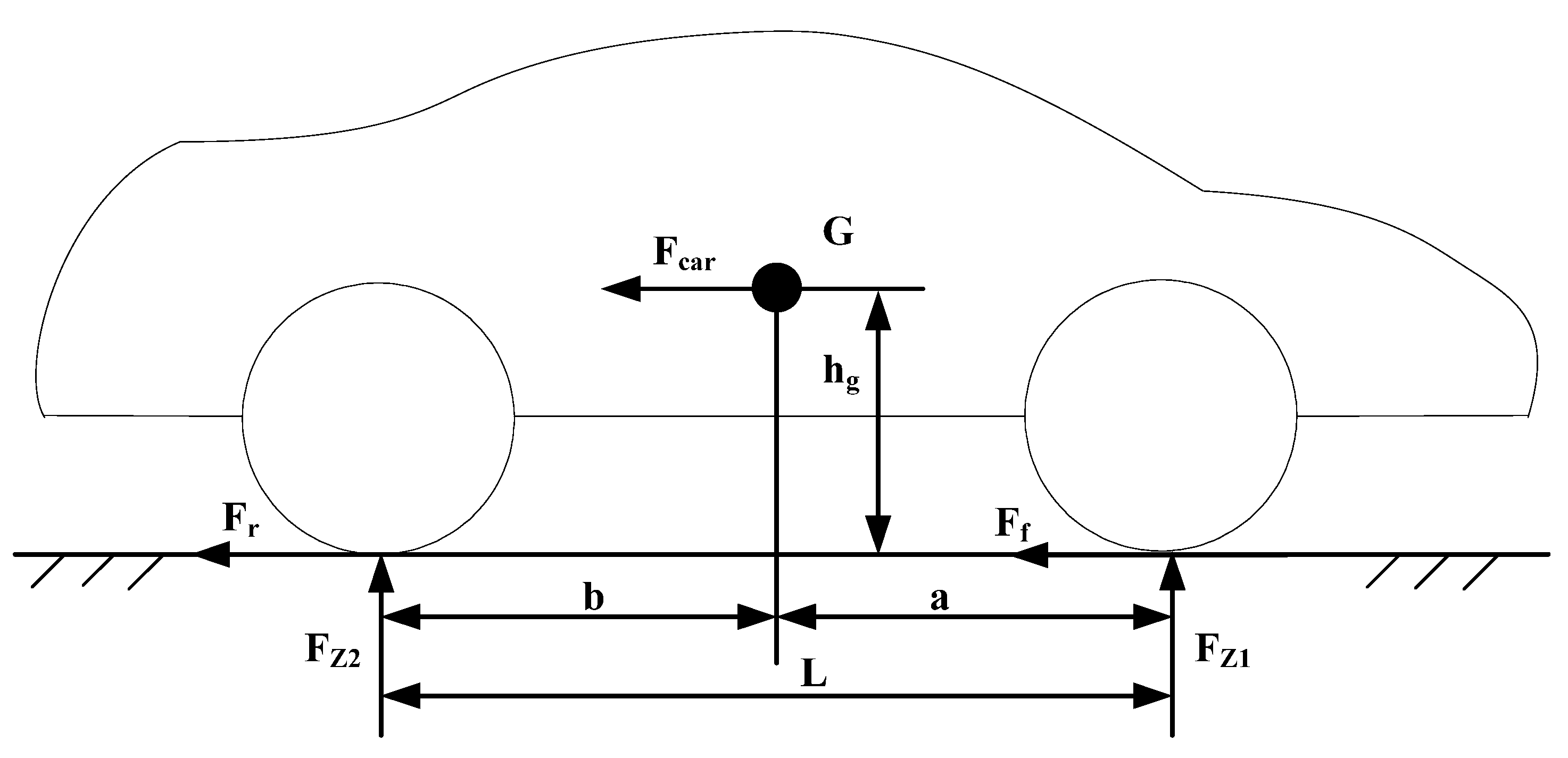
Figure 3 shows the principle of braking force distribution between front and rear wheels, which occurs when brake operations are performed while running on flat roads [
18]. The braking force
Fcar can be estimated from Equation (1) using the vehicle acceleration
αcar. The relationship between the vehicle braking force
Fcar and the front wheel braking force F
f and the rear wheel braking force
Fr can be represented as:
Figure 3.
Load movement which occurs when brake operations are performed while running on flat roads.
Figure 3.
Load movement which occurs when brake operations are performed while running on flat roads.
The load will be shifted from the rear wheel to the front wheel side when the brake pedal is stepped on, which will affect the distribution of braking force between front and rear wheels. To estimate the influence of load movement on braking, brake strength
z is defined as:
Accordingly, the maximum braking forces
Ff and
Fr which can be generated for the front and rear wheels are given by Equations (3)–(5):
where
Fz1 and
Fz2 are the normal force in front wheels and rear wheels, respectively,
G is vehicle total load;
φ represents the friction coefficient between the tire and the road surface.
The ideal distribution curve gives the maximum braking force which can make the front and rear wheels lock simultaneously for each friction coefficient. When the braking force is distributed to the front and rear wheels on the operating curve, safe braking is secured. It can be represented as:
As an example, the ideal braking force distribution characteristics were determined by calculations based on the specifications of the LF620 EV (
Table 2) and shown in
Figure 4.
Table 2.
LF620EV Parameters used for studying the proposed RBS.
Table 2.
LF620EV Parameters used for studying the proposed RBS.
| φ | 1 ~ 0.2 | Mcar | 1550 (kg) |
| L | 2.28 (m) | a | 1.0 (m) |
| Hg | 0.62 (m) | b | 1.28 (m) |
Figure 4.
Braking force distribution between front and rear wheels.
Figure 4.
Braking force distribution between front and rear wheels.
As shown in Equation (3) and Equation (4), braking forces
Ff and
Fr vary with the friction coefficient
φ. Thus, in order to distribute braking force according to the ideal curve, we need to obtain the friction coefficient in real time, but it is difficult to measure the changing friction coefficient directly. However, it can be found that the distribution ratio
Rf and
Rr of the front and rear wheels, does not depend on the friction coefficient [
18]:
The braking force Fcar can be estimated from Equation (1) using the detected acceleration αcar. From the above discussions, if an acceleration sensor is installed at the center of gravity of the body, the ideal braking force distribution can be performed. Therefore, an acceleration sensor is used in this study to realize the braking force distribution between front and rear wheels.
4. Regenerative Braking Strategy Design Based on Fuzzy Logic
Vehicle speed and the driver’s brake force command have large impacts on braking safety. Battery limitations such as battery capacity and the maximum permissible charging current play important roles in protecting them from damage. The capacity of the batteries can be obtained from the battery SOC. The maximum permissible charging current is a function of Q (battery capacity), T (battery temperature), SOC (state of charge), and SOH (state of health). I = f(Q, T, SOC, SOH). SOH is hard to be evaluated and play limited roles in calculating the maximum permissible charging current. Therefore, we only take SOC and battery temperature into consideration here. The relationships between the influence factors and the regenerative braking force are discussed in the following sections.
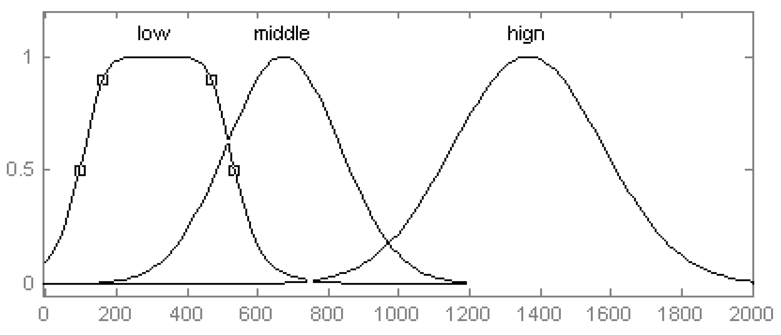
4.1. The Relationship between Driver’s Braking Force Command and the Regenerative Braking Force
The driver’s braking force commands are related to driving safety. The value of braking force represents the braking distance and time the driver requires to stop the vehicle. If the driver’s braking force command is large, it means the vehicle should be stopped in a short distance and time. At that time, we should decrease the proportion of regenerative braking force; when the driver’s braking force command is medium, the ratio of the regenerative braking force used should be increased; and in the last condition, the driver’s braking force command is small, so we can apply a large regenerative braking force to the vehicle. Therefore, we prefer the concourse of driver’s braking force command is: {low, middle, high} and the universe of discourse is [−10, 2000]. The membership functions are shown in
Figure 5.
Figure 5.
Membership functions of driver’s braking force commands.
Figure 5.
Membership functions of driver’s braking force commands.
4.2. The Relationship between Vehicle Speed and the Regenerative Braking Force
Vehicle speed plays an important role in ensuring braking safety and we should take the influence of the vehicle speed on the regenerative braking force into consideration. When the speed is low, to ensure the braking safety and satisfy relevant regulations, the regenerative braking force should take up a low proportion; when speed is medium, the regenerative braking force can increase to a suitable high level; when speed is high, we can increase the ratio of the regenerative braking force to the biggest value. Therefore, we prefer the set of speed as: {low, middle, high} and the universe of discourse is [−10, 200]. The membership functions can be seen in
Figure 6.
Figure 6.
Membership functions of speed.
Figure 6.
Membership functions of speed.
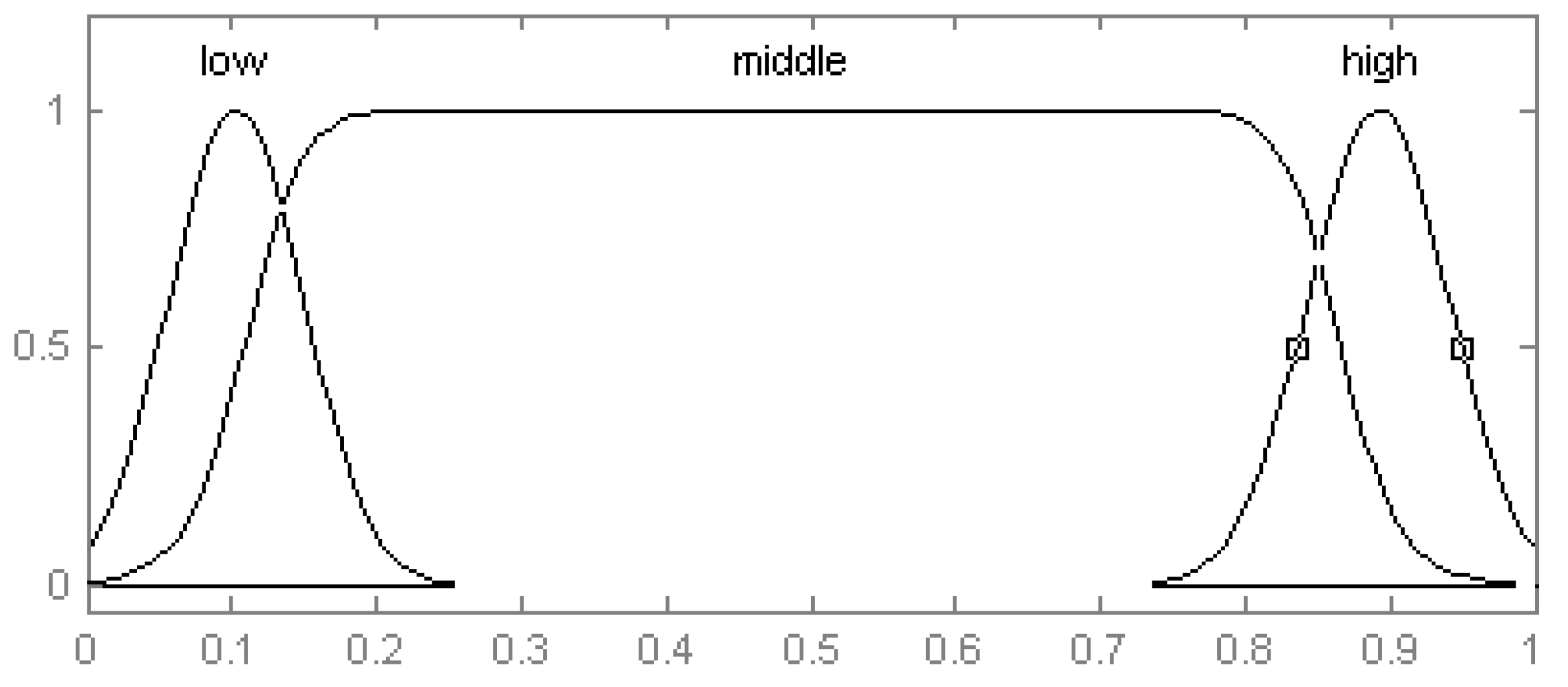
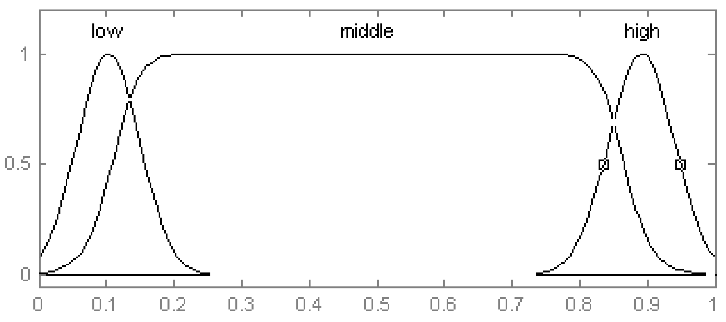
4.3. The Relationship between Battery SOC and the Regenerative Braking Force
When batteries’ SOC is lower than 10%, the inner resistance of the batteries has a high value and is unsuitable for charging, so at this time, the proportion of the regenerative braking force should be low; when the value of SOC is from 10% to 90%, the batteries can be charged with a large current and the proportion of the regenerative braking force should be increased correspondingly; when SOC is bigger than 90%, the charging current should be decreased to prevent deposit of lion and the value of regenerative braking force should be low, too. Therefore, we prefer the SOC set to be: {low, middle, high} and the universe of discourse is [0, 1]. The membership functions are shown in
Figure 7.
Figure 7.
Membership functions of SOC.
Figure 7.
Membership functions of SOC.
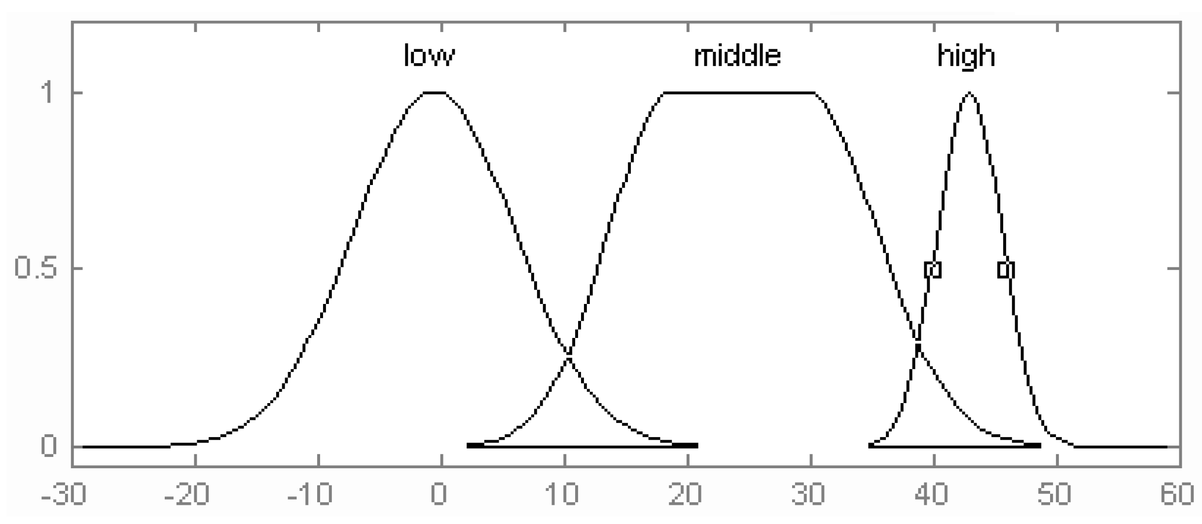
4.4. The Relationship between Battery Temperature and the Regenerative Braking Force
The relationship between batteries’ temperature and the maximum permissible charging current can be expressed by the following equations [
9]:
In the equations, kt is the compensation coefficient, kt1, kt2 are temperature coefficients and their values are different according to different companies. In terms of the criteria, kt1 = 0.33 and kt2 = 0.0549 when the current value is I at a temperature of 20 °C and the current becomes I/3 when the temperature decreases to 0 °C.
The relationship between battery temperature and the maximum permissible charging current shown in the equations cannot reflect the real relationships between battery temperature and the regenerative braking force [
23]. Therefore, we establish the relationship between them using fuzzy control logic according to the equations above.
When the temperature is low, we decrease the regenerative braking force while we increase its value the moment that the temperature is high. Therefore, we set the concourse of battery temperature as: {low, middle, high} and the changing range is [−30, 60]. The membership functions will be as seen in
Figure 8.
Figure 8.
Membership functions of battery temperature.
Figure 8.
Membership functions of battery temperature.
4.5. Outputs
The type of the fuzzy logic controller is a sugeno function. Therefore, we prefer the concourse of the ratio that the regenerative braking force takes in the total braking force is: Mf = {Mf0, Mf1, Mf2, Mf3, Mf4, Mf5, Mf6, Mf7, Mf8, Mf9, Mf10} = (0, 0.1, 0.2, 0.3, 0.4, 0.5, 0.6, 0.7, 0.8, 0.9, 1.0).
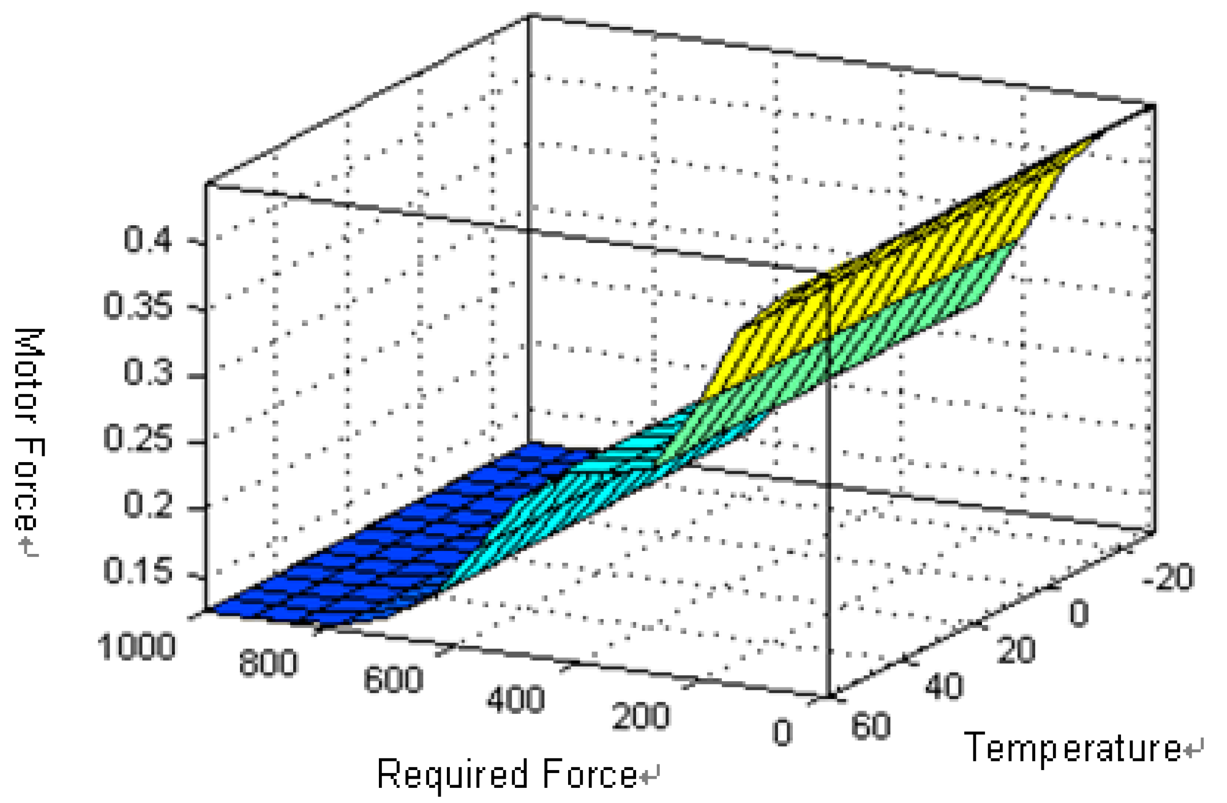
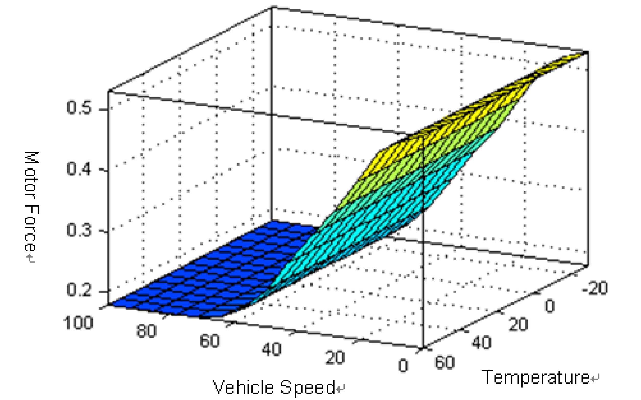
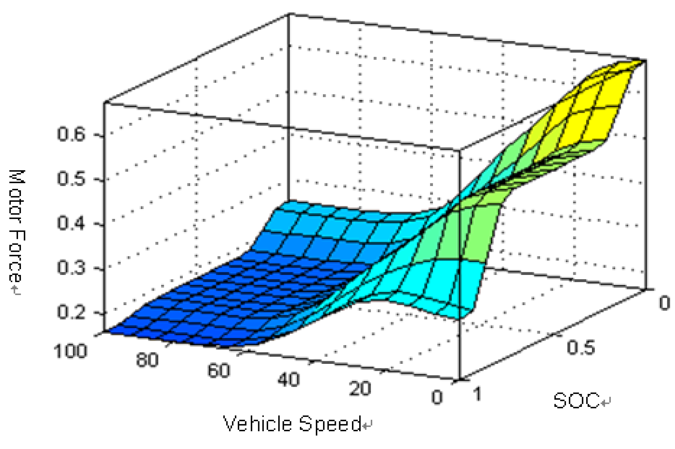
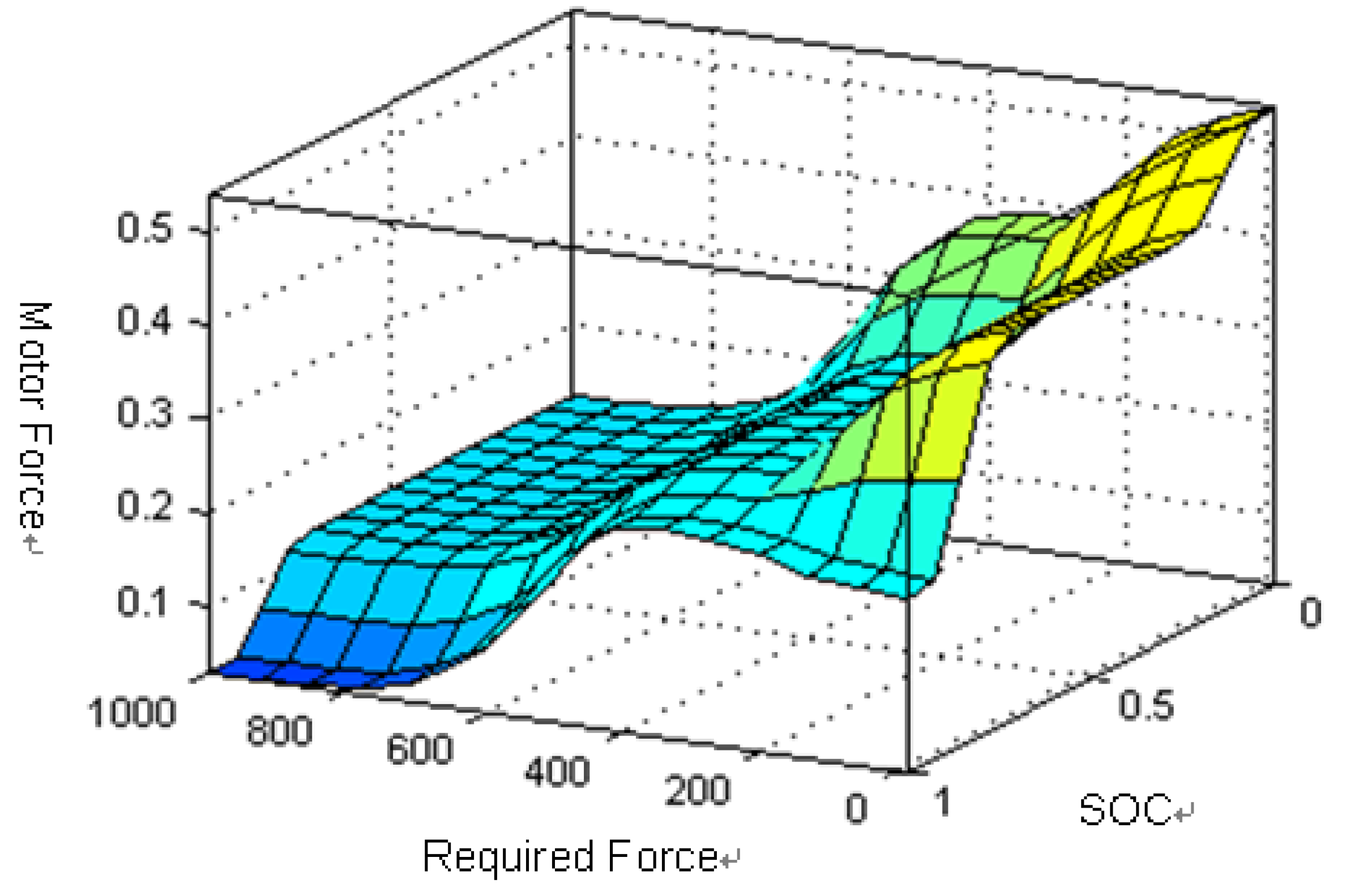
4.6. Rules
The control rules are the core of the entire fuzzy logic controller. The control model uses the form of three inputs and one output structure: IF premise 1, premise 2, premise 3 and premise 4 THEN conclusions; its fuzzy rules can be seen in
Table 3 and
Figure 9,
Figure 10,
Figure 11 and
Figure 12.
Table 3.
Fuzzy rules base.
Table 3.
Fuzzy rules base.
| Driver’s Braking Force Command | SOC | Vehicle Speed | Motor Force |
|---|
| high | high | high | Mf1 |
| middle | Mf1 |
| low | Mf0 |
| middle | high | Mf2 |
| middle | Mf2 |
| low | Mf1 |
| low | high | Mf3 |
| middle | Mf3 |
| low | Mf2 |
| middle | | high | Mf5 |
| high | middle | Mf3 |
| | low | Mf3 |
| | high | Mf7 |
| middle | middle | Mf5 |
| | low | Mf4 |
| | high | Mf8 |
| low | middle | Mf8 |
| | low | Mf4 |
| low | high | high | Mf6 |
| middle | Mf5 |
| low | Mf4 |
| middle | high | Mf10 |
| middle | Mf10 |
| low | Mf9 |
| low | high | Mf10 |
| middle | Mf10 |
| low | Mf9 |
Figure 9.
Relationships between driver’s braking force command, the battery temperature and motor force.
Figure 9.
Relationships between driver’s braking force command, the battery temperature and motor force.
Figure 10.
Relationships between vehicle speed, the battery temperature and the motor force.
Figure 10.
Relationships between vehicle speed, the battery temperature and the motor force.
Figure 11.
Relationships between vehicle speed, battery SOC and motor force.
Figure 11.
Relationships between vehicle speed, battery SOC and motor force.
Figure 12.
Relationships between driver’s braking force command, battery SOC and motor force.
Figure 12.
Relationships between driver’s braking force command, battery SOC and motor force.
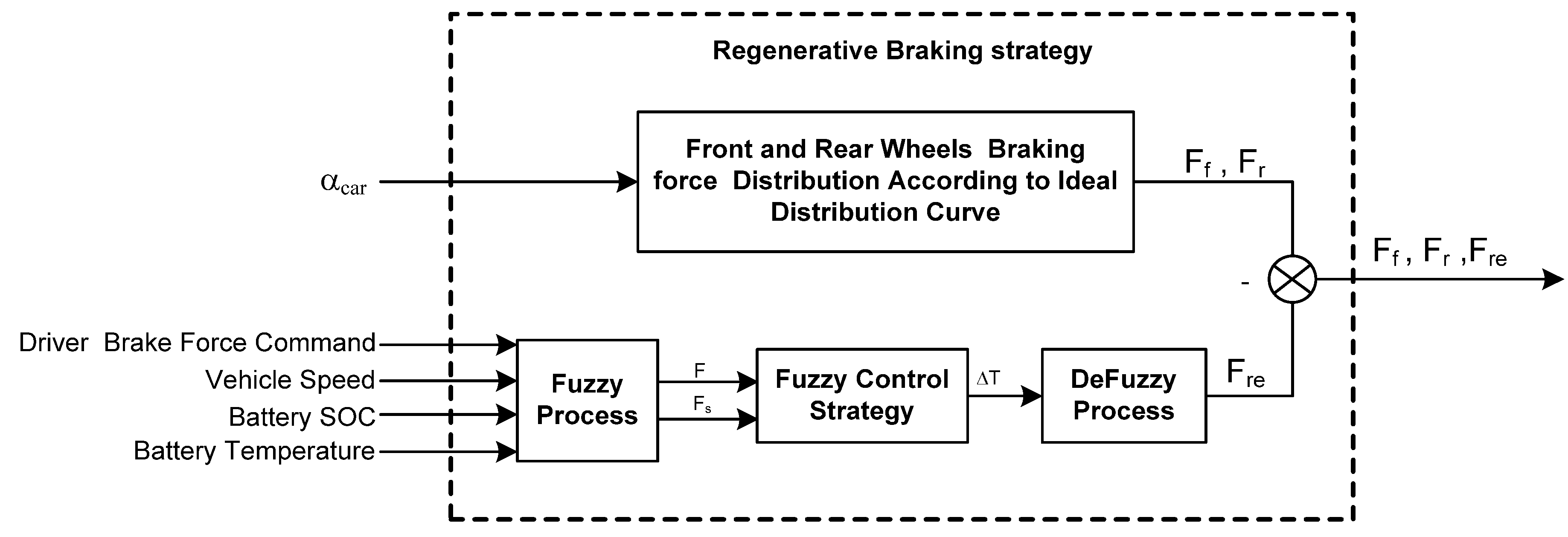
4.7. Regenerative Braking Strategy Based on Fuzzy Logic
The structure of the RBS is shown in
Figure 13.
Figure 13.
Structure of the control strategy system.
Figure 13.
Structure of the control strategy system.
From the above sections, we prefer four inputs of the fuzzy logic controller including battery temperature, SOC, vehicle speed and driver’s braking force command. The output is the regenerative braking force. Through the pedal sensor, we can determine the driver’s braking force command. According to the distribution regulations of braking force among front and rear wheels, the front braking force and the rear braking force can be calculated, respectively. Then, according to the fuzzy logic controller, the value of regenerative braking force can be established.
5. Experimental Results and Discussion
The fuzzy RBS had been predesigned using simulation before actual testing on vehicles to test its stability and performance. It is also essential to predesign the RBS under a great variety of driving cycles to gain a level of insight which would normally take an impractical amount of time and effort using actual experiments. Thus we built a vehicle model according to the parameters of the LF620 EV as shown in
Table 1 and
Table 2 using the electric vehicle simulation software ADVISOR. This integrated model is simulated under standard driving cycle EPA Urban Dynamometer Driving Schedule (UDDS).
To evaluate the performance and effectiveness of the fuzzy RBS, the simulation results are compared with a conventional rule-based RBS embedded in ADVISOR.
Figure 14 shows the changing curve of battery SOC. The red line represents the SOC curve under fuzzy RBS conditions. The blue line represents the rule-based RBS conditions. It can be seen about an extra 2% of the battery capacity energy is saved with the fuzzy RBS in one UDDS cycle. This means more energy is produced and recycled by the motor.
Figure 14.
Simulation results under UDDC cycle.
Figure 14.
Simulation results under UDDC cycle.
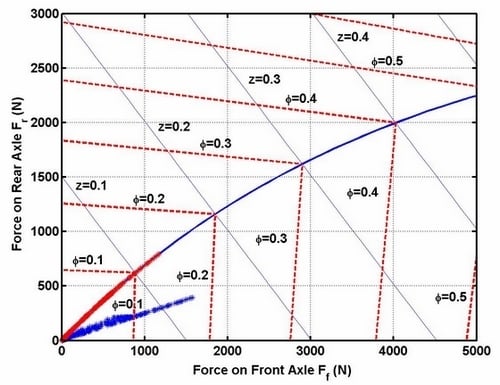
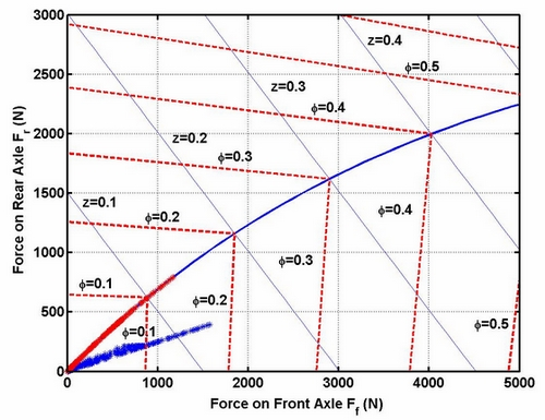
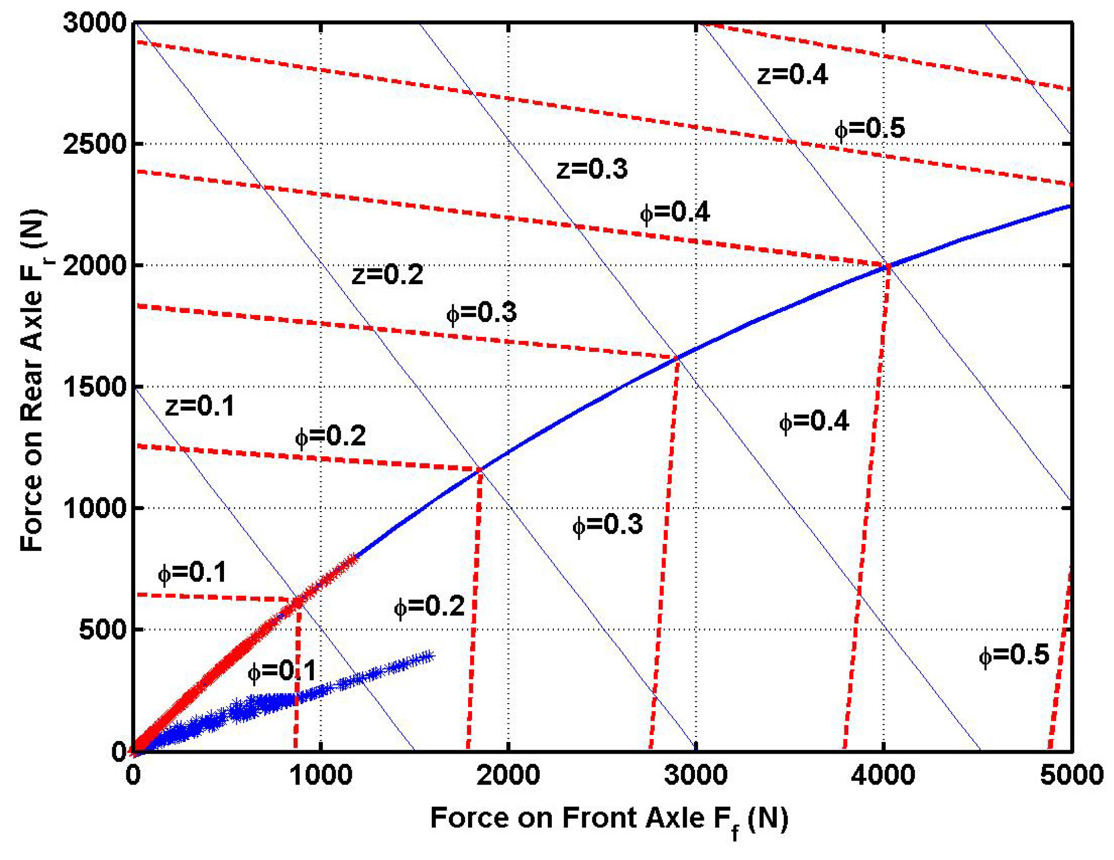
Figure 15 shows the braking force distribution between front and rear wheels for EV under different RBSs. Due to the fact we can get the ideal distribution ratio by adding an acceleration sensor, the red points located on the ideal distribution curve under fuzzy RBS will ensure the driving stability of vehicle under emergency braking conditions, whereas the blue points under the rule-based RBS deviate substantially from ideal curve, which may lead to the rear wheels locking first under emergency braking conditions. Locking of rear wheels is especially dangerous because the vehicle may spin.
Figure 15.
Braking force distribution between front and rear wheels.
Figure 15.
Braking force distribution between front and rear wheels.
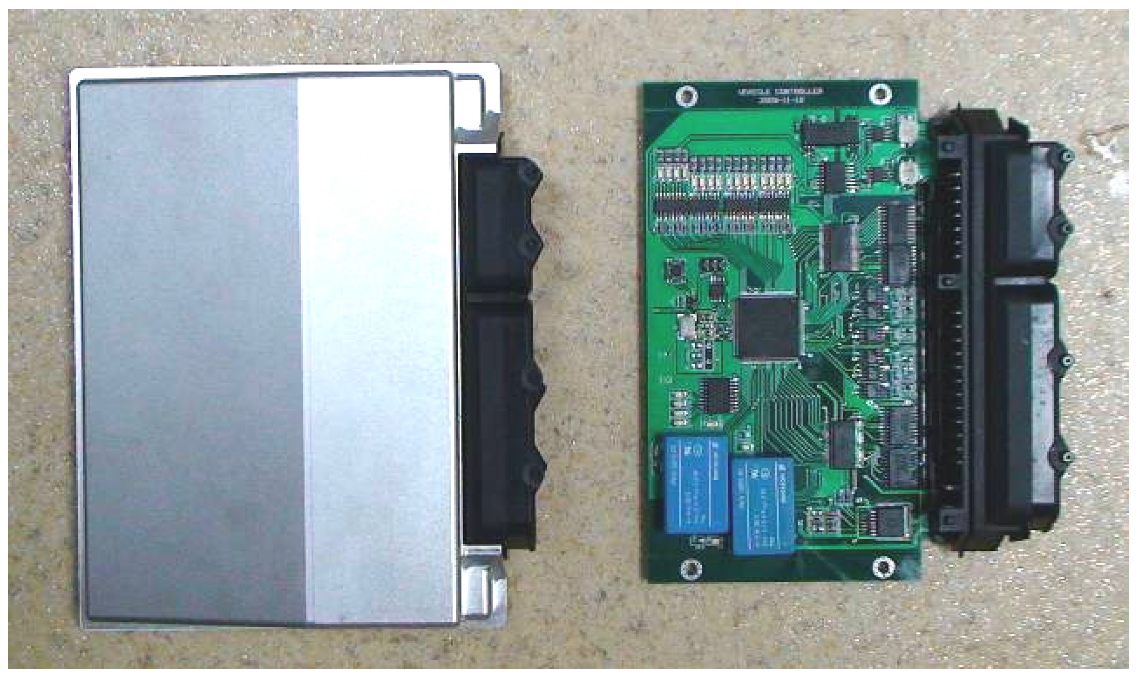
The proposed fuzzy RBS was then implemented on a vehicle control unit (VCU) hardware and applied on the LF620 prototype EV. The VCU’s photo is shown in
Figure 16.
Figure 16.
Vehicle controller photo.
Figure 16.
Vehicle controller photo.
Freescale MC9S12XEP100 was selected as the main chip of the VCU. It is a 16-bit micro controller unit, and can operate at a maximum frequency of 50 MHz, providing adequate computational performance. The VCU uses a CAN communication interface. This allows for rapid communication with subsystem controllers to transfer orders and data. The VCU samples some parameters such as vehicle acceleration, vehicle velocity, diver brake force command, discharge current value and so on. The SOC values and battery temperature are provided by the battery management system (BMS). The VCU was also equipped with a FM25640 storage cell, a 64 KB FRAM memory chip with an SPI interface, to save important parameters, when power is removed. An ADXL202E dual axis accelerometer was selected as the vehicle acceleration sensor.
To evaluate the performance and effectiveness of the fuzzy RBS, the LF620 EV is driven naturally and continuously on an urban road until the battery is over used. The comparative experiment is conducted many times to find the difference between the maximum driving range under RBS and non-RBS conditions. The experiment results for the fuzzy RBS are shown in
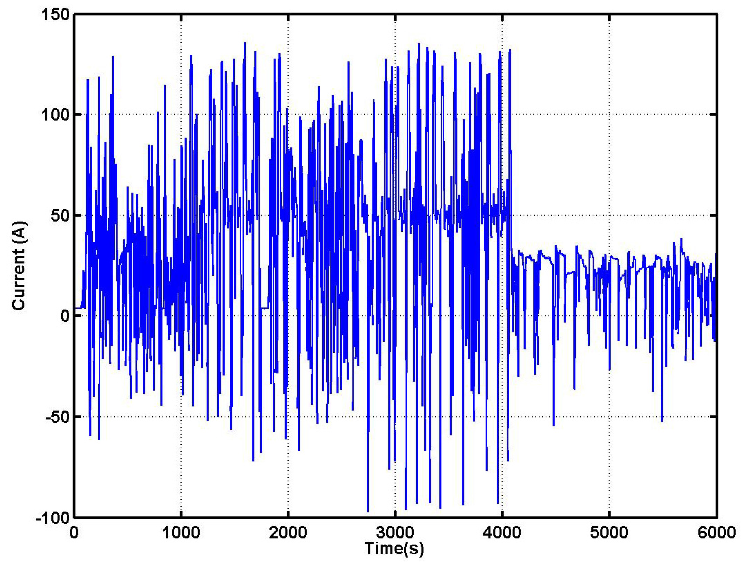
Figure 17 and
Figure 18 and
Table 4. It can be seen that the fuzzy RBS achieves very good results. Both the component efficiency and maximum driving range are improved significantly compared to the non-RBS condition.
Figure 17.
Current curve.
Figure 17.
Current curve.
Table 4.
Experimental Results.
Table 4.
Experimental Results.
| Item | NON-RBS | Fuzzy RBS | Improvement |
|---|
| Motor/controller efficiency | 0.67 | 0.78 | 16.4% |
| Overall energy efficiency | 0.341 | 0.417 | 22.2% |
| Maximum driving range (km) | 163 | 205 | 25.7% |
From the results above, some useful conclusions are obtained and the effectiveness of the fuzzy RBS is verified.
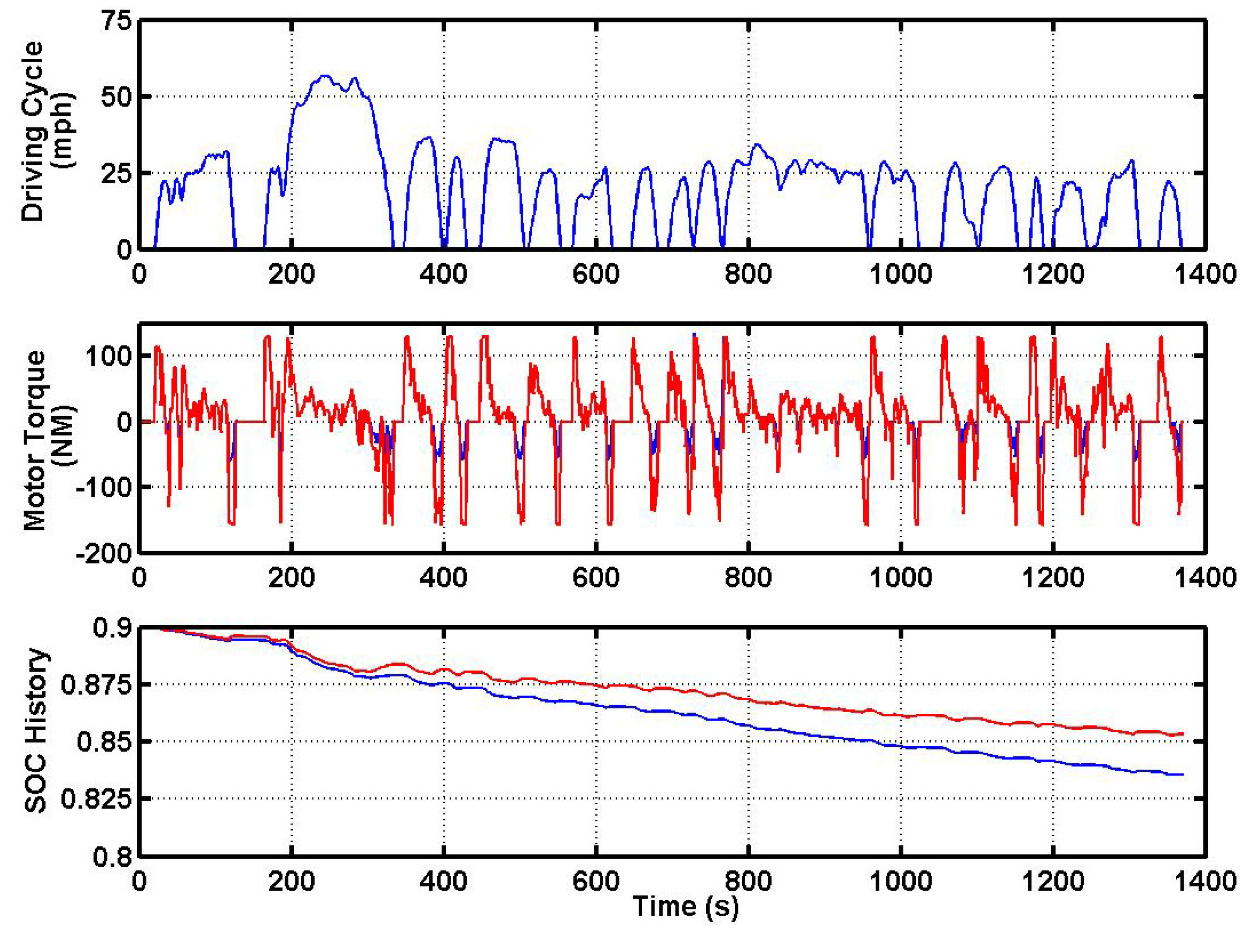
Figure 17 shows the current curve achieved during the urban driving experiment. From the figure we can see that the motor works frequently in generation mode.
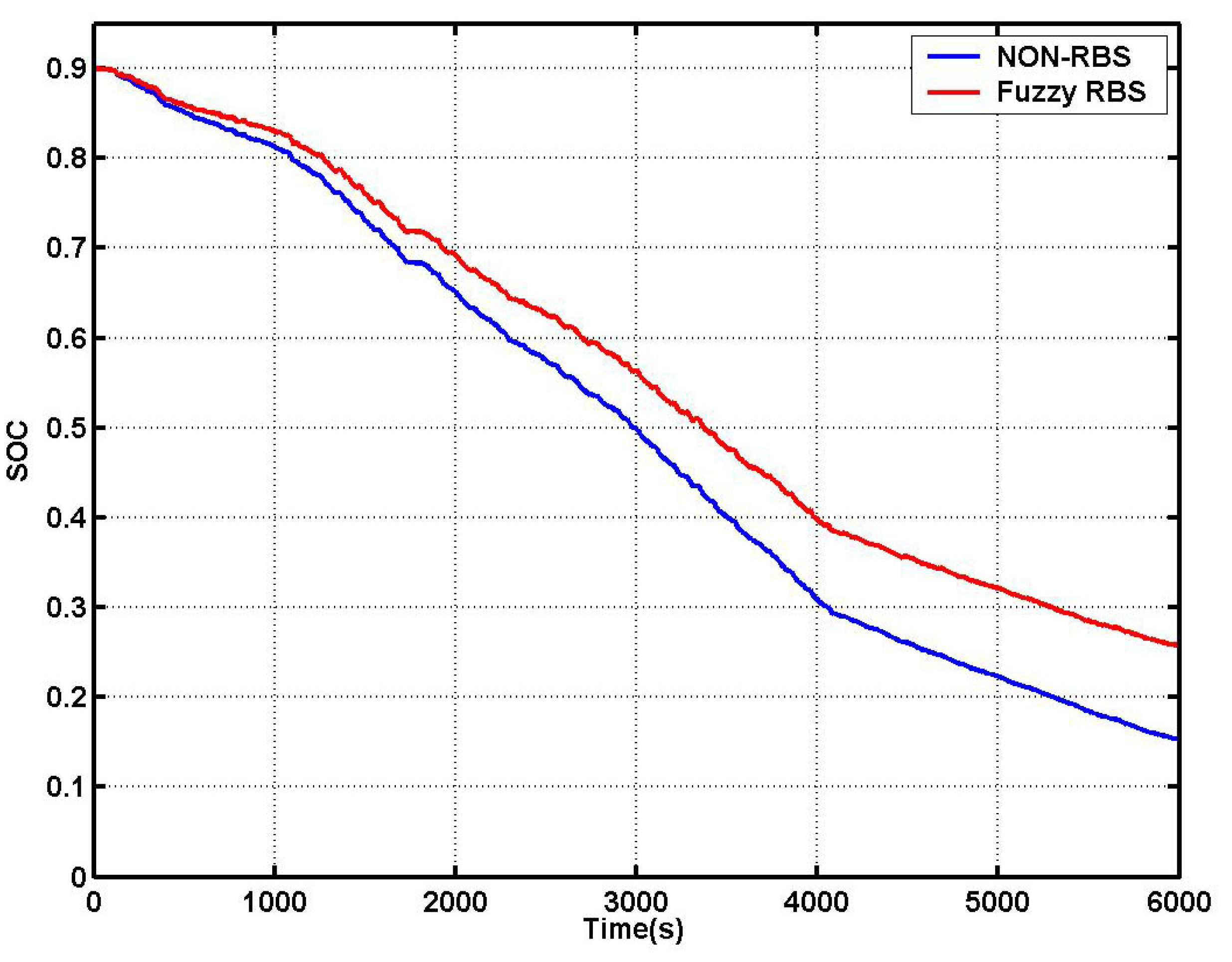
Figure 18 shows the changing curve of battery SOC. The red line represents the SOC curve under fuzzy RBS conditions. The blue line represents the non-RBS conditions. They are calculated by setting the negative current value to zero. We can see that about an extra 11% of the battery capacity energy is saved with the fuzzy RBS. This means more energy is produced and recycled by the motor; regarding
Table 4, we can see an obvious improvement of the efficiency of the motor and overall energy efficiency. The overall energy efficiency improved from 0.341 to 0.417, an improvement of about 22%. The immediate consequence is that the maximum driving range of EV is extended from 163 kilometers to 205 kilometers, almost a 26% improvement. From the experimental results and discussions above, we can see the validity of the fuzzy RBS in improving the energy efficiency of EVs while ensuring driving safety conditions.
6. Conclusions
The energy-saving, powertrain efficiency and braking stability performance of electric vehicles depends to a large extent on their regenerative braking strategy. The article has analyzed the braking effectiveness and braking stability, and presented a fuzzy RBS to improve the braking performance. The fuzzy RBS effectively solves the braking force distribution between front and rear wheels, and the distribution between friction braking force and regenerative braking force. What’s more, the fuzzy RBS is applied and tested on a LF620 prototype EV on the road. Experimental results show that it can realize maximum recovery vehicle braking energy while meeting braking safety requirements. The powertrain and component efficiency are evidently improved and the maximum driving range per charge of the EV can be extended. They are the most convincing evidence to verify the effectiveness of the regenerative braking method in recycling braking energy which otherwise is wasted as heat through friction.


