Supplementary Controller Design for SSR Damping in a Series-Compensated DFIG-Based Wind Farm

Abstract
:1. Introduction
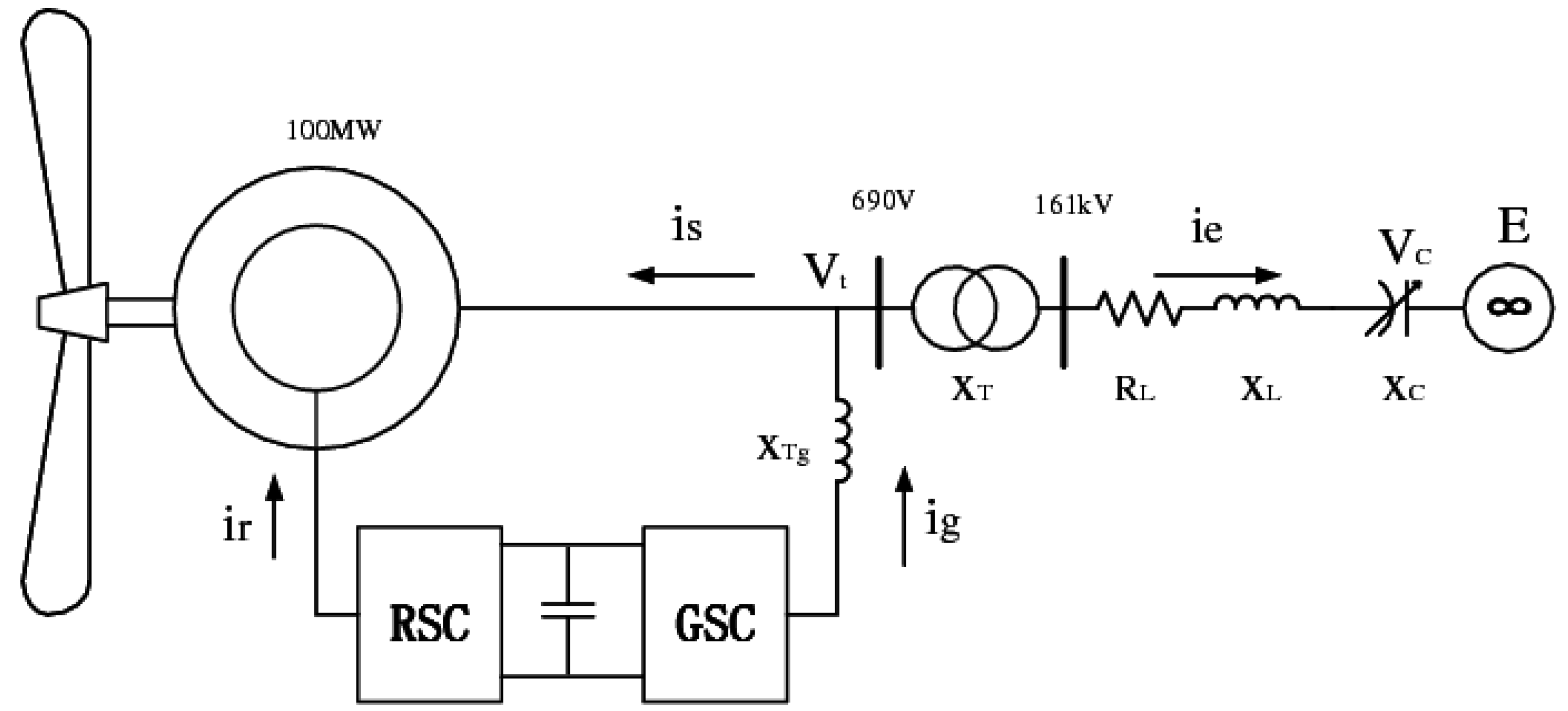
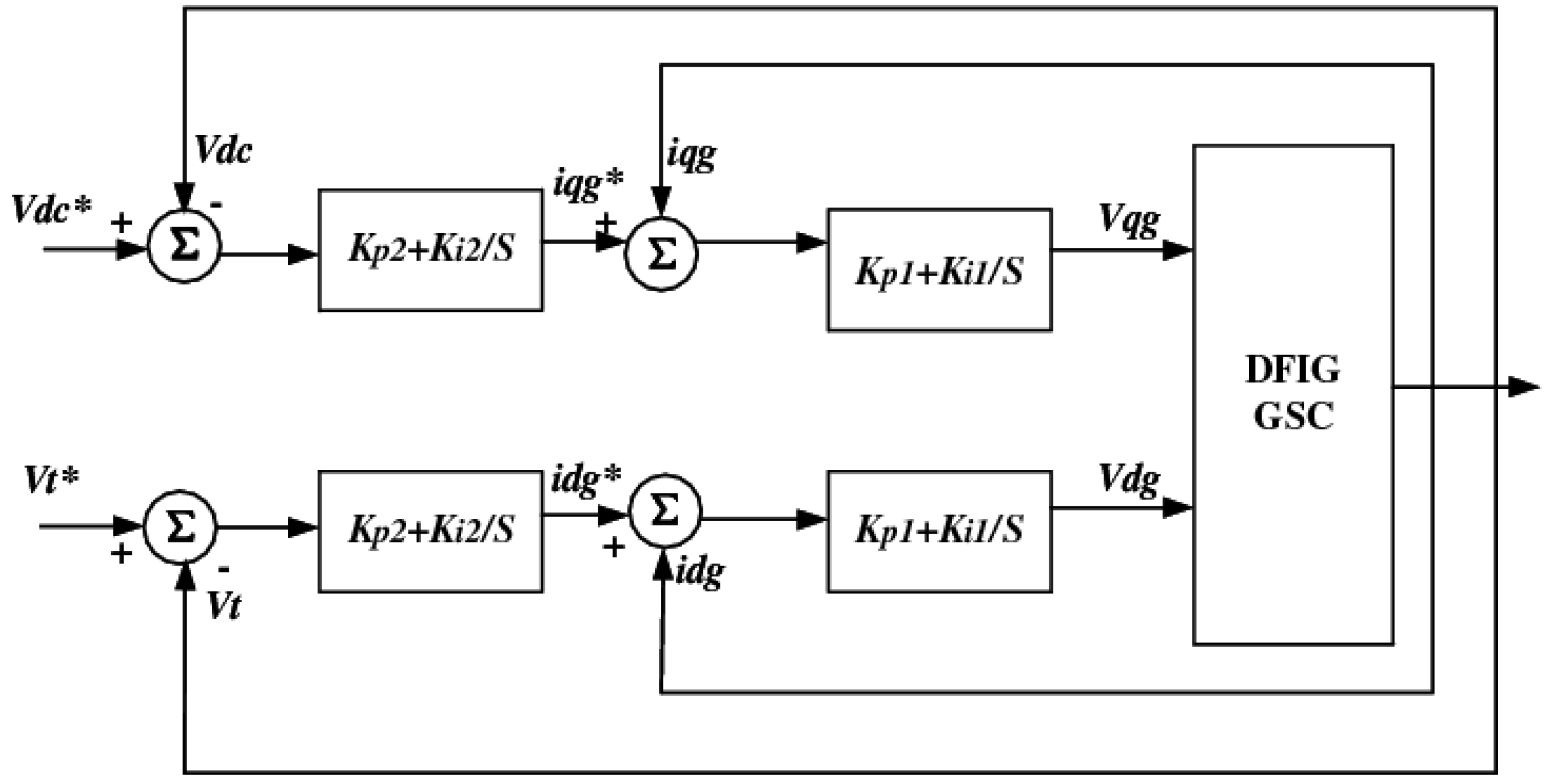
2. System Structure
3. Modal Controllability, Observability, Residue and Their Effects
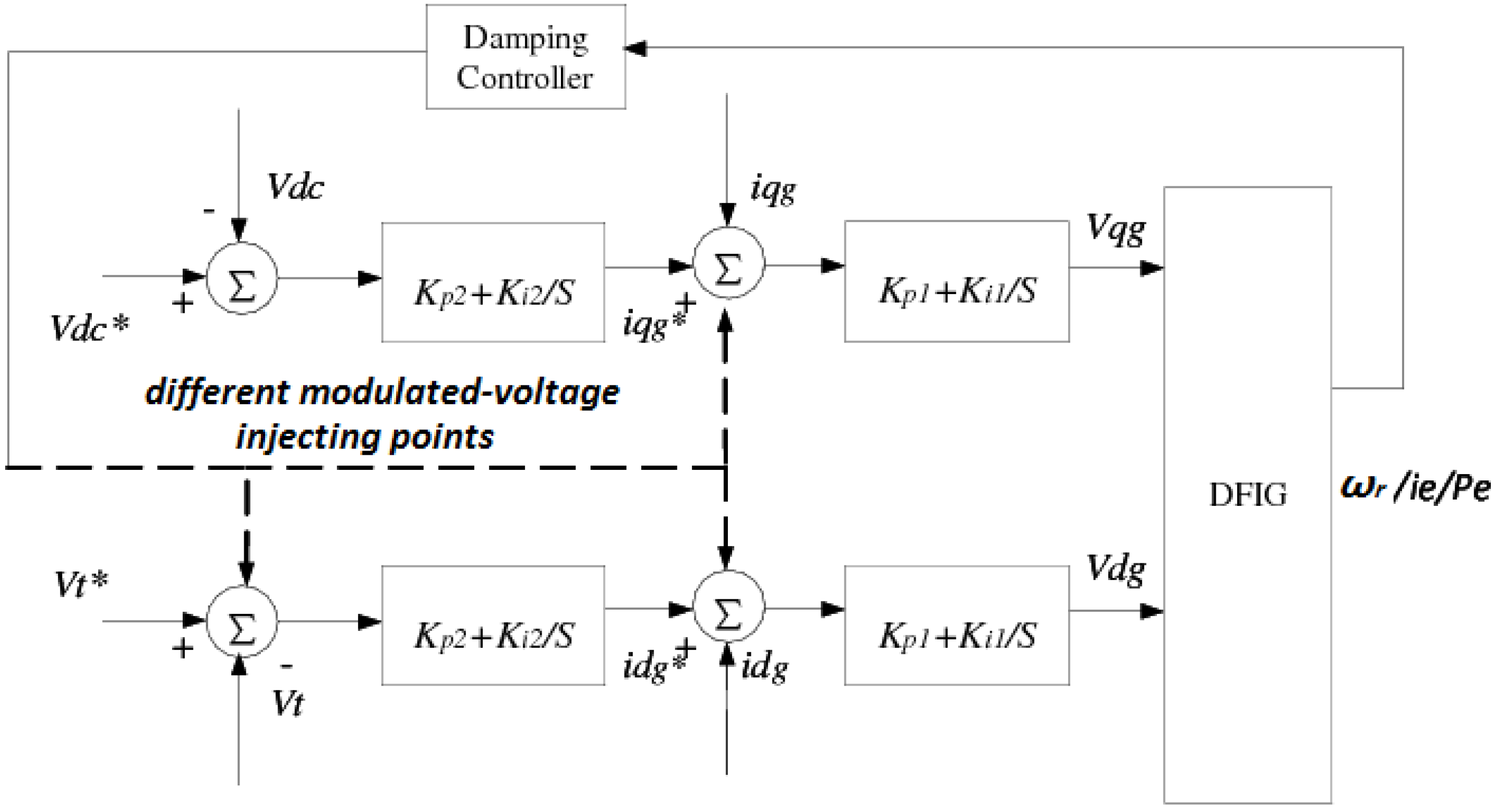
4. Comparison of Feedback Signals and Modulated-Voltage Injecting Points
4.1. Base Case

| Mode | Λ = ρ ± jω | Frequency | Damping ratio | Nature of the Mode |
|---|---|---|---|---|
| λ1,2 | 4.9 ± j123.2 | 19.6079 | −0.0397 | SSR mode |
| λ3,4 | −10.4 ± j629 | 100.1085 | 0.0165 | Super synchronous resonance mode |
| λ5,6 | −12.7 ± j99.1 | 15.7723 | 0.1271 | Electromechanical mode |
| λ7,8 | −1 ± j5.8 | 0.9231 | 0.1699 | Shaft mode |
4.2. Modal Controllability, Observability and Residue for Different Feedback Signals and Different Modulated-Voltage Injecting Points
| Feedback signal | Modulated-voltage injecting point | Observability | Controllability | Residue | |||
|---|---|---|---|---|---|---|---|
| Magnitude | Phase | Magnitude | Phase | Magnitude | Phase | ||
| Rotor speed | d-axis of GSC outer loop | 0.0001 | −21.0564 | 4.1891 | −49.1602 | 0.004 | −70.2166 |
| d-axis of GSC inner loop | 0.0001 | −21.0564 | 41.9 | 131.0720 | 0.04 | 110.0156 | |
| q-axis of GSC inner loop | 0.0001 | −21.0564 | 31 | 94.6664 | 0.0296 | 73.6101 | |
| Line current | d-axis of GSC outer loop | 0.2741 | −112.4409 | 4.1891 | −49.1602 | 1.1484 | −161.6011 |
| d-axis of GSC inner loop | 0.2741 | −112.4409 | 41.9 | 131.0720 | 11.482 | 18.6311 | |
| q-axis of GSC inner loop | 0.2741 | −112.4409 | 31 | 94.6664 | 8.5031 | −17.7745 | |
| Electrical power | d-axis of GSC outer loop | 0.1945 | 67.3696 | 4.1891 | 130.8398 | 0.8147 | −161.7906 |
| d-axis of GSC inner loop | 0.1945 | 67.3696 | 41.9 | −48.9280 | 8.146 | 18.4416 | |
| q-axis of GSC inner loop | 0.1945 | 67.3696 | 31 | −85.3335 | 6.0327 | −17.964 | |
- The magnitude of modal observability for the line current as the feedback signal is high, and the electrical power has high modal observability too. Therefore, the line current and electrical power are both the candidate appropriate signals to damp SSR with less control effort.
- The magnitude of modal controllability for the d-axis of the GSC inner loop as the modulated-voltage injecting points is large, and the q-axis of GSC inner loop has large modal controllability too. Hence, less gain is required for these controlling points for the supplementary SSR damping control design.
- The magnitude of the modal residue for the rotor speed as the feedback signal is very small, which means a large control effort (gain). Meanwhile, the phase lag of the modal residue is high. Thus, the feedback control design requires both gain and phase compensation.
- The magnitude of the modal residue for the line current as the feedback signal is large, and the phase lag of the modal residue is low. Therefore, only gain compensation is required and phase compensation will not be used, which results in a simple feedback control design.
- The magnitude and phase of the modal residue for the electrical power as the feedback signal are similar to those for the line current as the feedback signal. Similarly, only gain compensation is required. Hence, the feedback control design will also be fairly simple.
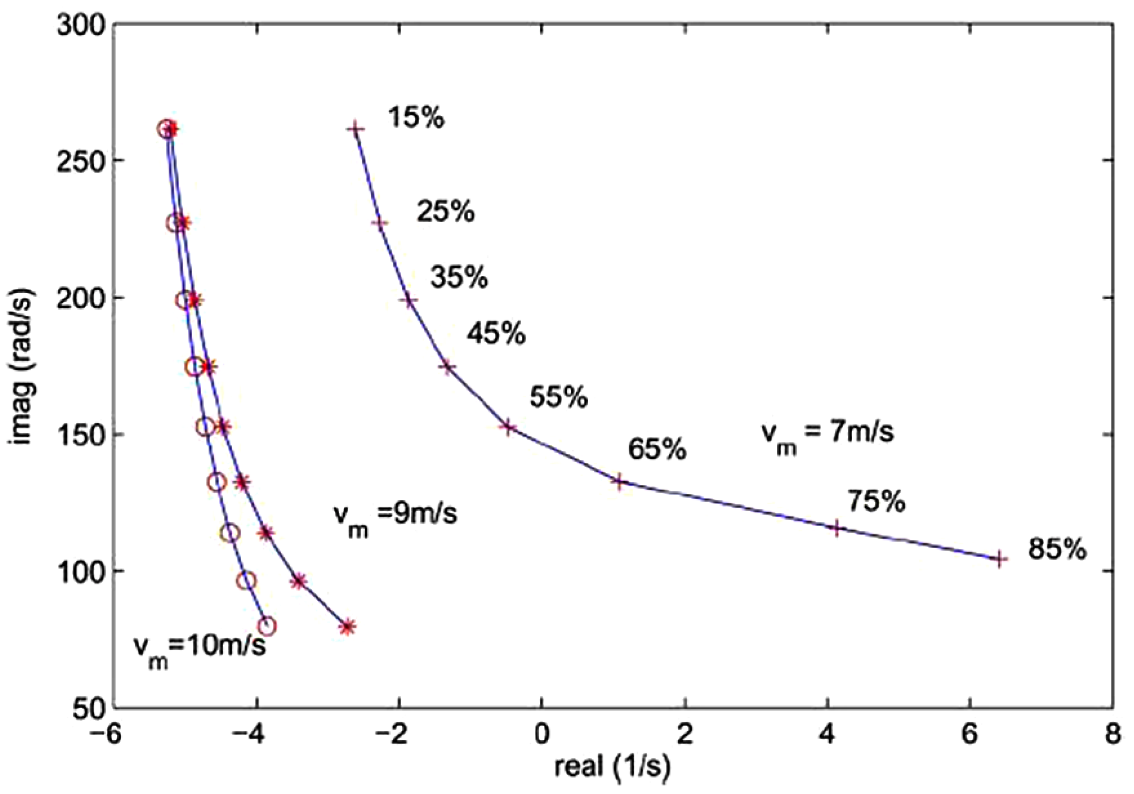
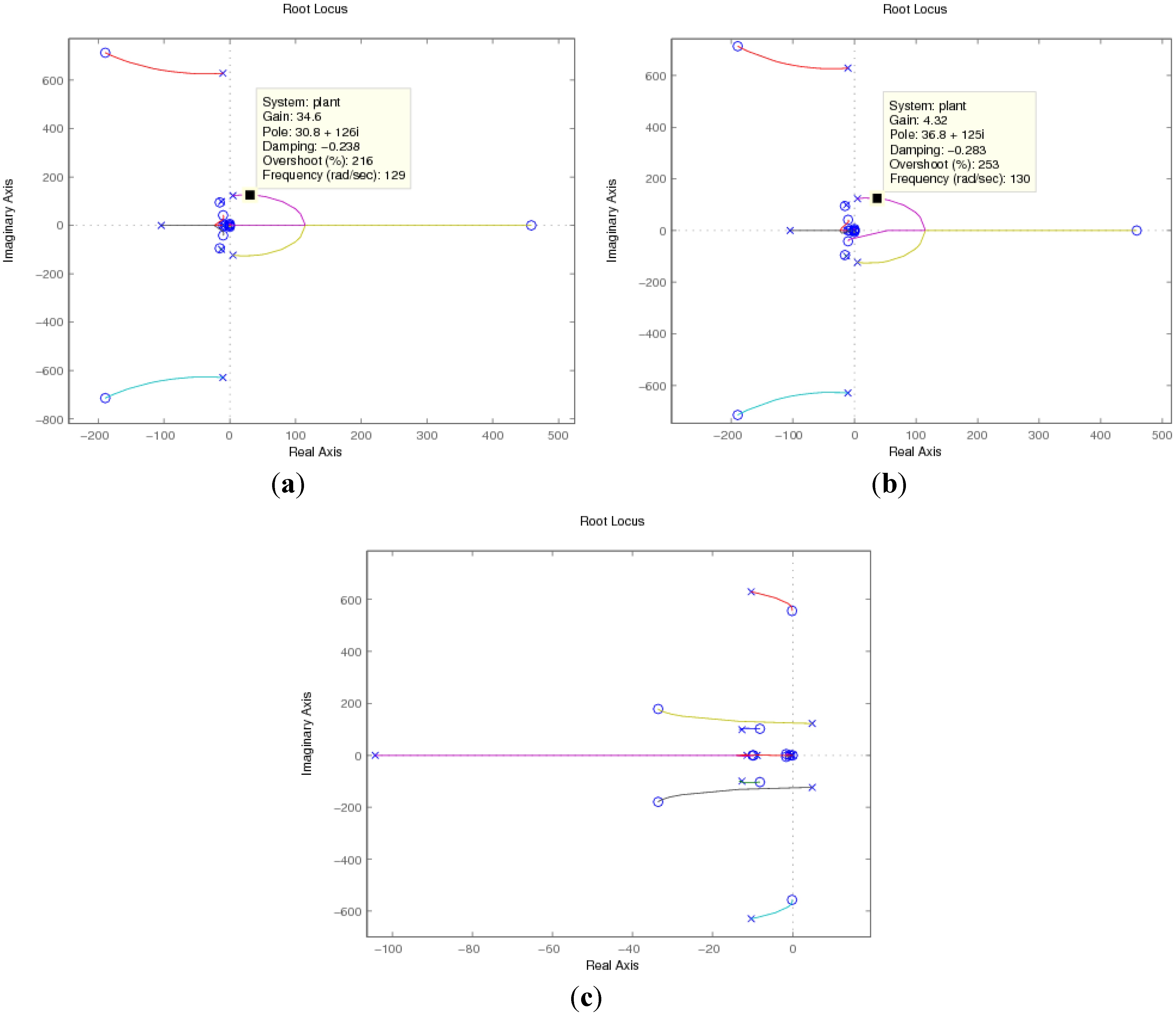
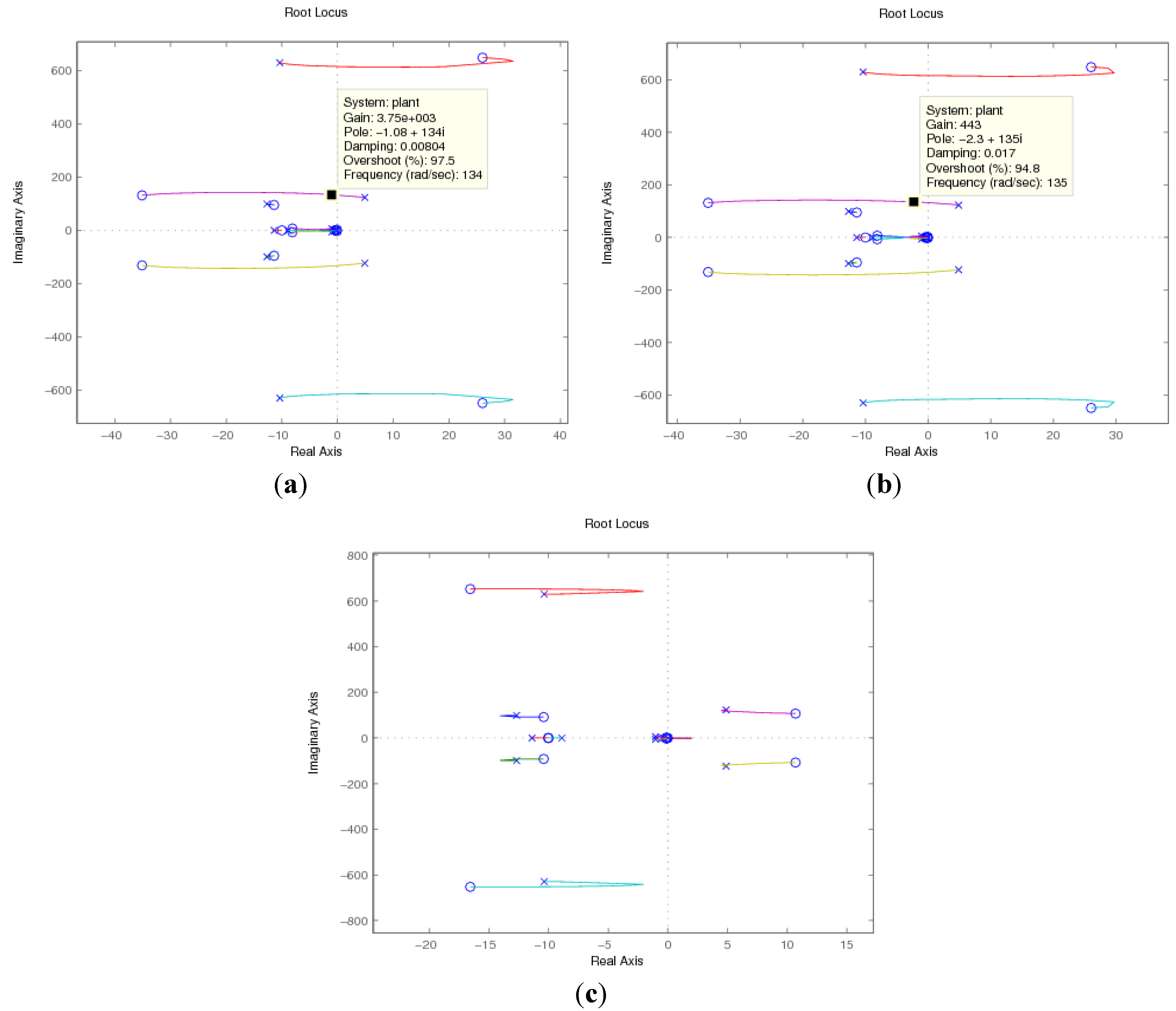
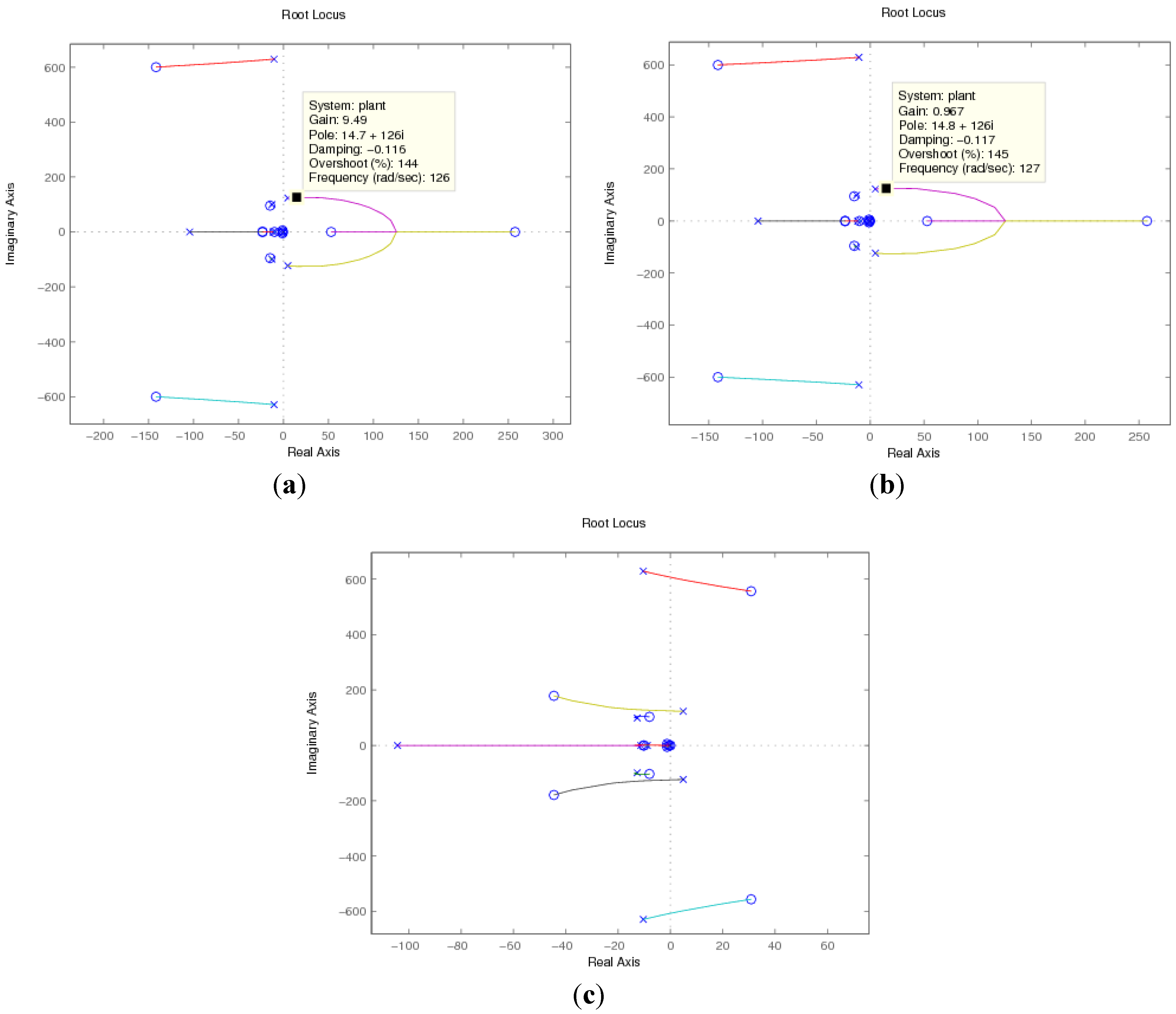
4.3. Root Locus Analysis Verification

5. Time Domain Simulation Results Verification
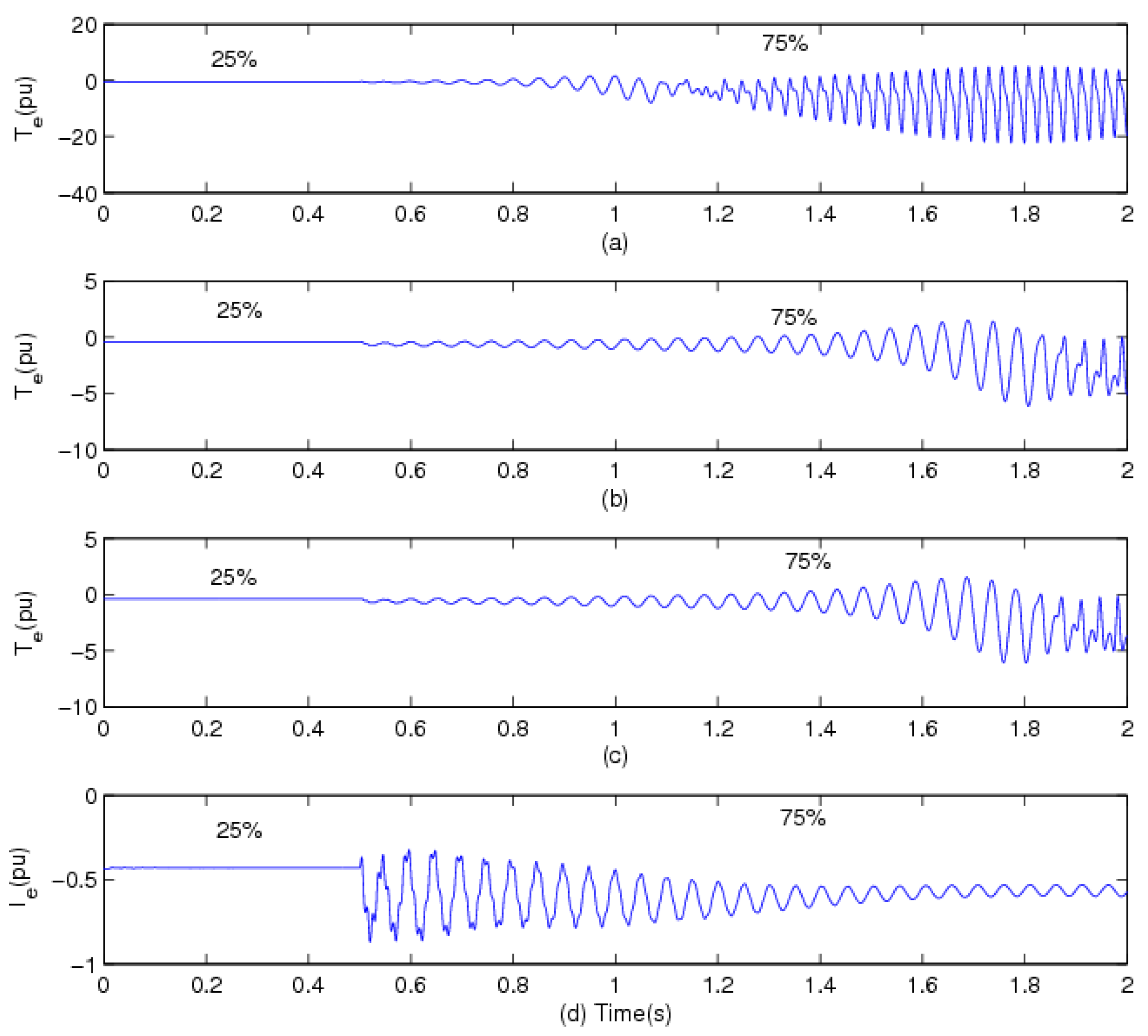
5.1. Simulation Results for the Rotor Speed as a Feedback Signal of the Supplementary Control Loop
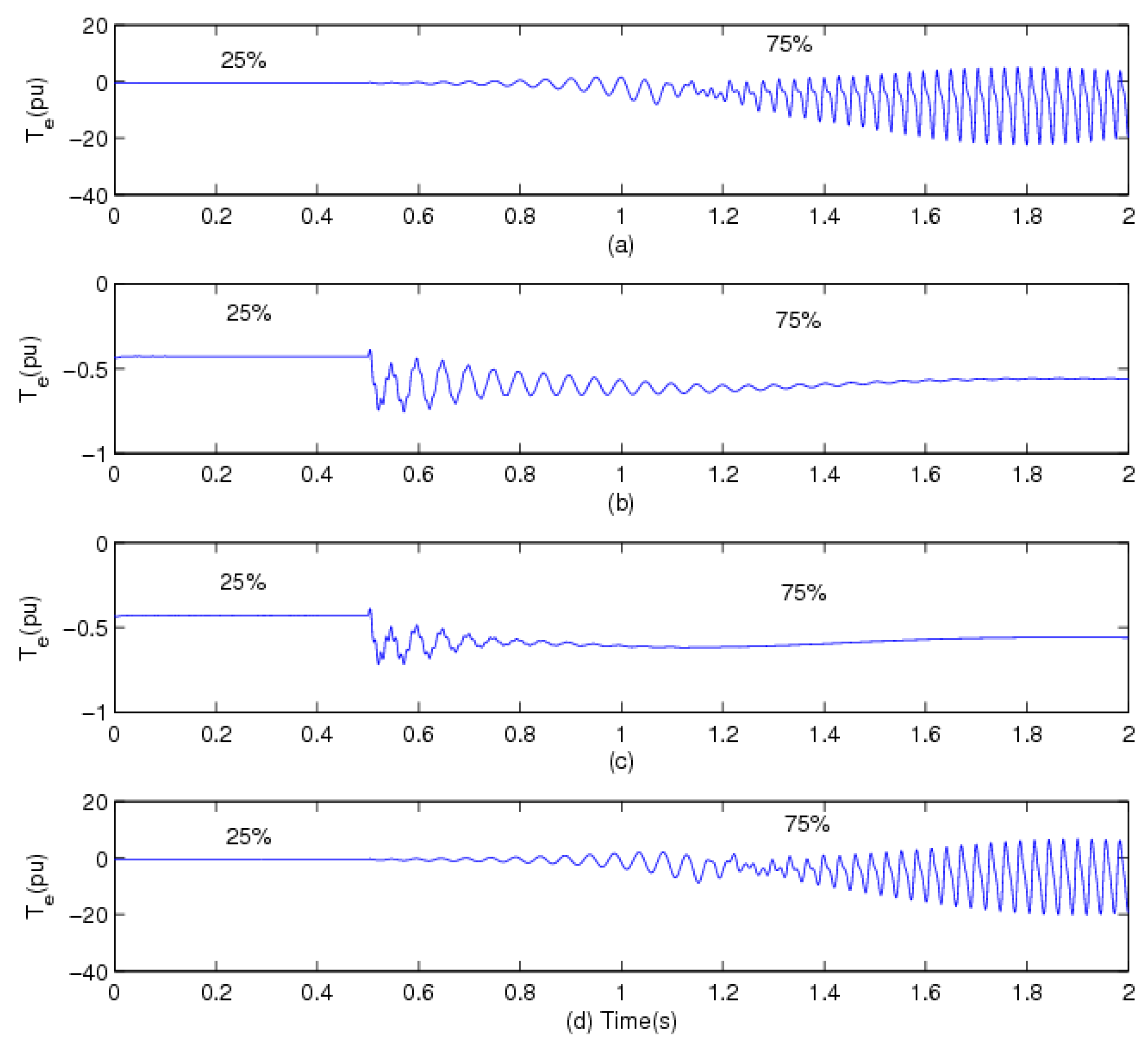
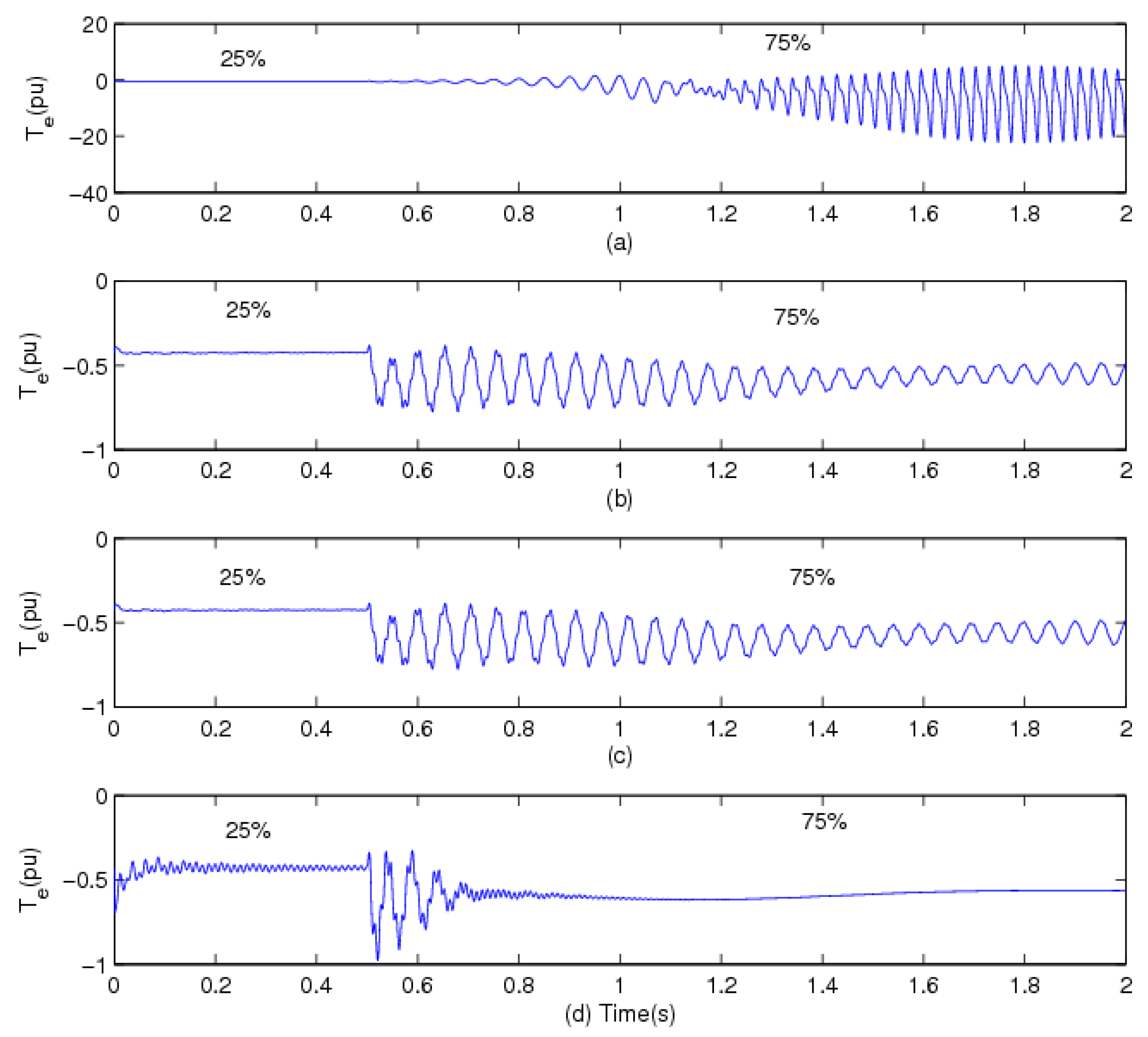
5.2. Simulation Results for the Line Current as the Feedback Signal of the Supplementary Control Loop
5.3. Simulation Results for the Electrical Power as the Feedback Signal of the Supplementary Control Loop


6. Conclusions
Acknowledgments
References
- Varma, R.K.; Auddy, S.; Semsedini, Y. Mitigation of subsynchronous resonance in a series-compensated wind farm using FACTS controllers. IEEE Trans. Power Deliv. 2008, 3, 1645–1654. [Google Scholar] [CrossRef]
- Raii, D.; Faried, S.; Ramakrishna, G.; Edris, A. Hybrid series compensation scheme capable of damping subsynchronous resonance. IET Generat. Transm. Distrib. 2010, 4, 456–466. [Google Scholar] [CrossRef]
- El-Moursi, M.S.; Bak-Jensen, B.; Abdel-Rahman, M.H. Novel STATCOM controller for mitigating SSR and damping power system oscillations in a series compensated wind park. IEEE Trans. Power Electron. 2010, 2, 429–441. [Google Scholar] [CrossRef]
- Hughes, F.M.; Anaya-Lara, O.; Jenkins, N.; Strbac, G. A power system stabilizer for DFIG-based wind generation. IEEE Trans. Power Syst. 2006, 21, 763–772. [Google Scholar] [CrossRef]
- Kahatriya, N.; Annakkage, U.D.; Hughes, F.M.; Gole, A.M. Optimized partial eigenstructure assignment-based design of a combined PSS and active damping controller for a DFIG. IEEE Trans. Power Syst. 2010, 25, 866–876. [Google Scholar] [CrossRef]
- Miao, Z.; Fan, L.; Osborn, D.; Yuvarajan, S. Control of DFIG based wind generation to improve interarea oscillation damping. IEEE Trans. Energy Convers. 2009, 24, 415–422. [Google Scholar] [CrossRef]
- Fan, L.; Yin, H.; Miao, Z. On active/reactive power modulation of DFIG-based wind generation for interarea oscillation damping. IEEE Trans. Energy Convers. 2011, 26, 513–521. [Google Scholar] [CrossRef]
- Ostadi, A.; Yazdani, A.; Varma, R.K. Modeling and stability analysis of a DFIG-based wind-power generator interfaced with a series-compensated line. IEEE Trans. Power Deliv. 2009, 24, 1504–1514. [Google Scholar] [CrossRef]
- Knuppel, T.; Nielsen, J.N.; Jensen, K.H.; Dixon, A.; Ostergaard, J. Power oscillation damping controller for wind power plant utilizing wind turbine inertia as energy storage. In Proceedings of IEEE Power and Energy Society General Meeting 2011, San Diego, CA, USA, 24–29 July 2011.
- Zhu, C.; Fan, L.; Hu, M. Control and analysis of a DFIG-based wind turbine in a series compensated network for SSR damping. In Proceedings of IEEE Power and Energy Society General Meeting 2010, Minneapolis, MN, USA, 25–29 July 2010.
- Faried, S.O.; Unal, I.; Rai, D.; Mahseredjian, J. Utilizing DFIG-Based wind farms for damping SSR in nearby turbine-generators. IEEE Trans. Power Syst. 2012, 99. [Google Scholar] [CrossRef]
- Padiyar, K. Analysis of Subsynchronous Resonance in Power Systems; Springer: New York, NY, USA, 1999. [Google Scholar]
- Fan, L.; Kavasseri, R.; Miao, Z.; Zhu, C. Modeling of DFIG-based wind farms for SSR analysis. IEEE Trans. Power Deliv. 2010, 25, 2073–2082. [Google Scholar] [CrossRef]
- IEEE Committee. First benchmark model for computer simulation of subsynchronous resonance. IEEE Trans. Power Appar. Syst. 1977, 96, 1565–1672. [Google Scholar]
- Miller, N.W.; Sanchez-Gasca, J.J; Price, W.W.; Delmerico, R.W. Dynamic modeling of GE 1.5 and 3.6 MW wind turbine-generators for stability simulations. In Proceedings of IEEE Power Engineering Society General Meeting 2003, Toronto, Canada, 13–17 July 2003.
- Zhu, C.; Fan, L.; Hu, M. Modeling and simulation of a DFIG-based wind turbine for SSR. In Proceedings of North American Power Symposium (NAPS) 2009, Starkville, MS, USA, 4–6 October 2009.
- Pal, B.; Chaudhuri, B. Robust Control in Power Systems; Springer: New York, NY, USA, 2005. [Google Scholar]
- Zhang, X.P.; Rehtanz, C.; Pal, B. Flexible AC Transmission Systems: Modelling and Control; Springer: New York, NY, USA, 2012. [Google Scholar]
- Fan, L.; Zhu, C.; Miao, Z.; Hu, M. Modal analysis of a DFIG-based wind farm interfaced with a series compensated network. IEEE Trans. Energy Convers. 2011, 26, 1010–1020. [Google Scholar] [CrossRef]
- Martins, N.; Lima, L.T.G. Determination of suitable locations for power system stabilizers and static VAR compensators for damping electromechanical oscillations in large scale power systems. IEEE Trans. Power Syst. 1990, 5, 1455–1469. [Google Scholar] [CrossRef]
- Swakshar, R.; Balarko, C.; Rajat, N. Appropriate signal selection for damping multi-modal oscillations using low order controllers. In Proceedings of IEEE Power and Energy Society General Meeting—Conversion and Delivery of Electrical Energy in the 21st Century 2008, Pittsburgh, PA, USA, 20–24 July 2008.
- Kuo, B.C.; Golnaraghi, F. Automatic Control Systems, 8th ed.; Wiley: New York, NY, USA, 2002. [Google Scholar]
Appendix
| 2 MW DFIG | Network system | ||
|---|---|---|---|
| Rated power | 2 MW | Transformer ratio | 690 V/161 kV |
| Rated voltage | 690 V | Base MVA | 100 MVA |
| Xls | 0.09231 pu | RL | 0.02 pu (5.1842 Ω) |
| XM | 3.95279 pu | XL | 0.5 pu (129.605 Ω) |
| Xlr | 0.09955 pu | XT | 0.14 pu (36.2894 Ω) |
| Rs | 0.00488 pu | XC at 50% compensation level | 64.8 Ω |
| Rr’ | 0.00549 pu | Series compensation C | 40 μF |
| H | 3.5 s | Line length | 154 miles |
| Xtg | 0.3 pu | ||
| Ht | 4.29 s |
|---|---|
| Hg | 0.9 s |
| Dt | 0 pu |
| Dg | 0 pu |
| Dtg | 1.5 pu |
| Ktg | 0.15 pu |
© 2012 by the authors; licensee MDPI, Basel, Switzerland. This article is an open access article distributed under the terms and conditions of the Creative Commons Attribution license (http://creativecommons.org/licenses/by/3.0/).
Share and Cite
Wu, Z.; Zhu, C.; Hu, M. Supplementary Controller Design for SSR Damping in a Series-Compensated DFIG-Based Wind Farm. Energies 2012, 5, 4481-4496. https://doi.org/10.3390/en5114481
Wu Z, Zhu C, Hu M. Supplementary Controller Design for SSR Damping in a Series-Compensated DFIG-Based Wind Farm. Energies. 2012; 5(11):4481-4496. https://doi.org/10.3390/en5114481
Chicago/Turabian StyleWu, Zaijun, Chanxia Zhu, and Minqiang Hu. 2012. "Supplementary Controller Design for SSR Damping in a Series-Compensated DFIG-Based Wind Farm" Energies 5, no. 11: 4481-4496. https://doi.org/10.3390/en5114481
APA StyleWu, Z., Zhu, C., & Hu, M. (2012). Supplementary Controller Design for SSR Damping in a Series-Compensated DFIG-Based Wind Farm. Energies, 5(11), 4481-4496. https://doi.org/10.3390/en5114481