1. Introduction
Energy crises, environmental issues and concerns regarding peaking oil production have promoted research into development of various types of new energy vehicles, which has been established as one of the seven strategic emerging industries in China. Electric vehicles (EVs), which include battery electric vehicles (BEVs), hybrid electric vehicles (HEVs) and plug-in hybrid electric vehicles (PHEVs), are the main development subject for new energy vehicles [
1,
2,
3]. Electric vehicles (EVs) are emerging as important personal transportation options for petroleum displacement and energy diversification. The battery, as a key component, is crucial for the performance features of EVs, such as economy, power performance, security,
etc. [
4].
The lithium-ion battery is widely used in many fields because of its advantages of high voltage, low self-discharge and long cycle-life. High specific energy, in particular, makes it a promising candidate for EVs. In such applications, a battery management system (BMS) is critical for maintaining optimum battery performance [
5]. Accurate peak power estimates are critical in practical applications since it is necessary to determine the power available in the moment to meet the acceleration, regenerative braking and gradient climbing power requirements without fear of over-charging or over-discharging the battery and thus reducing its lifespan. More importantly, accurate online peak power capability estimates for the battery will optimize the relation between the battery capacity and the vehicle’s performance, which benefits the vehicle’s general potency [
6].
Some peak power capability estimation approaches are presented with the development of EVs technology [
6,
7,
8,
9]. The commonly used method is the hybrid pulse power characterization (HPPC) method proposed by the Idaho National Engineering & Environmental Laboratory, which is used for determining the static peak power in laboratory environments [
7]. However, it is not suitable for estimating the continuous peak currents that are available for the next sample intervals Δ
ts and neglects design limits like cell current, cell power or the state of charge (SoC) [
8]. In order to overcome the drawbacks of the HPPC method, which is not suitable for continuous peak power capability prediction, and neglecting the SoC limits, the voltage-limited method was proposed by Plett [
9]. However, the
Rint model-based HPPC and voltage-limited method are not suitable for estimating the battery’s peak power capability due to the fact that it can hardly simulate the dynamic voltage performance.
Based on an analysis of the traditional methods [
8] proposes a dynamic battery power estimation algorithm taking into account design limit constraints on current, voltage and SoC. The authors of [
6] propose a model-based dynamic multi-parameter method for peak power capability estimations, and its comparison with other commonly used methods shows it is more useful than others. Unfortunately, the battery is a strongly non-linear and time-variable system because of its complicated electrochemical processes; its state parameters, such as the equivalent internal resistance, open-circuit voltage (OCV) and available capacity, will be changed to some extent due to the influence of the operation environment, aging and other factors, therefore the model parameters identified by offline methods, which the above two peak power estimation methods use, can hardly be used for a long time with high accuracy. Furthermore, the peak power capability estimation accuracy is always strongly dependent on the reliability of the tabulated OCV-SoC data. In addition, the experiments for collecting the tabulated OCV-SoC data are often time-consuming and error-prone, especially for lithium-ion batteries, which have quite flat OCV-SoC curves. Lastly, it is very challenging to test and verify the developed peak power capability estimation algorithm in the early development stage due to limited resources and time.
The well known software MATLAB/Simulink of Math-Works has been widely used in dynamic system modeling and simulation of control algorithms, and the MATLAB toolbox xPC Target provides us a rapid prototyping host-target environment to construct a real time control system in the manner of a hardware-in-the-loop (HIL) test. The software xPC Target is a solution for prototyping, testing, and deploying real-time systems using standard PC hardware [
10,
11]. The HIL test has been extensively used in the automotive industry for component development and rapid prototyping. Usually the target component under development is tested within a modeled system environment that reproduces the conditions under which the component will operate. With system-level requirements taken into consideration, HIL tests significantly reduce the time and costs of system-level integration and troubleshooting later in the development cycle [
12]. The work in this paper aims at developing and verifying the online peak power capability estimation using xPC Target for on-board BMS applications.
This paper makes use of a 3.7 V/35 A h LiMn
2O
4 lithium-ion cell as research subject. The paper is arranged as follows:
Section 2 proposes an online parameter identification algorithm for the dynamic electrochemical-polarization (EP) battery model with the Simulink/xPC software;
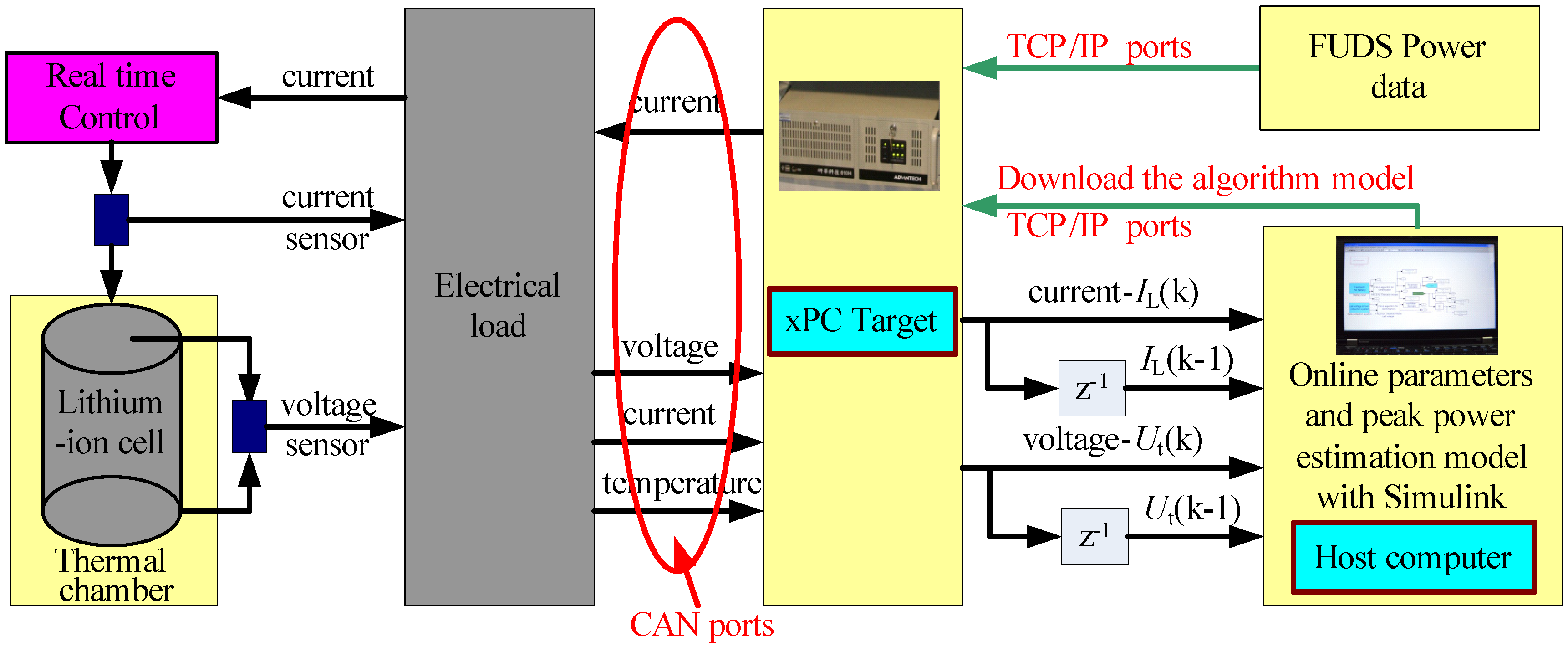
Section 3 proposes an online dynamic peak power capability estimation algorithm based on the dynamic EP model and designs a HIL test bench;
Section 4 carries out the HIL test and evaluates the proposed method for hybrid electric vehicle (HEV) application; last is the conclusion of this paper.
4. Results and Discussion
Firstly, the cell capacity check test is run to check the cell’s present maximum available capacity. After being properly initialized (the cell’s design limits are shown in
Table 1), the battery then runs through a verification profile of the Federal Urban Driving Schedules (FUDS) [
18,
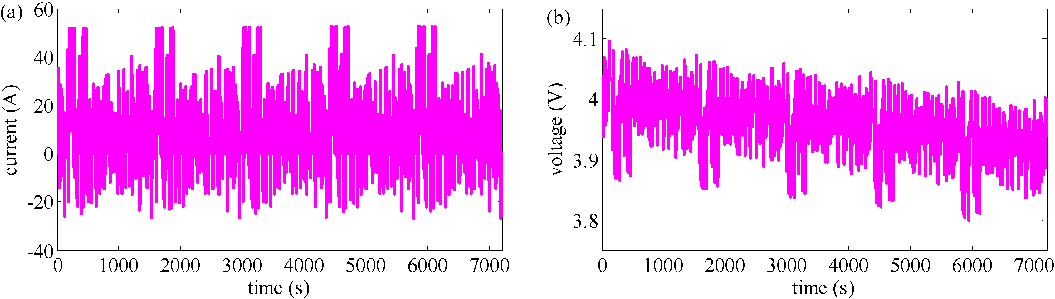
19] on the HIL bench downloaded from the xPC Target. The measured current and voltage profiles of the FUDS are shown in
Figure 3. To simplify the analysis for the peak power capability calculation results, the SoC is calculated by the ampere counting method, which is useful in a laboratory environment. The initial SoC is set at 0.85. The battery model takes measured voltages, currents, and temperatures of the battery from HIL testing as inputs, and calculates the SoC as an input for the model and estimates the power capabilities over time.
Table 1.
The cell’s design limits for the HIL test.
Table 1.
The cell’s design limits for the HIL test.
| Parameters | Value |
|---|
| Maximum load current /A | 350 |
| Minimum load current /A | 175 |
| Maximum terminal voltage /V | 4.2 |
| Minimum terminal voltage /V | 3.0 |
| Peak discharge power /W | 1500 |
| Peak charge power /W | −700 |
| SoC operation range for HEVs | 0.35–0.85 |
Figure 3.
The measured profiles of the FUDS cycles: (a) current; (b) voltage.
Figure 3.
The measured profiles of the FUDS cycles: (a) current; (b) voltage.
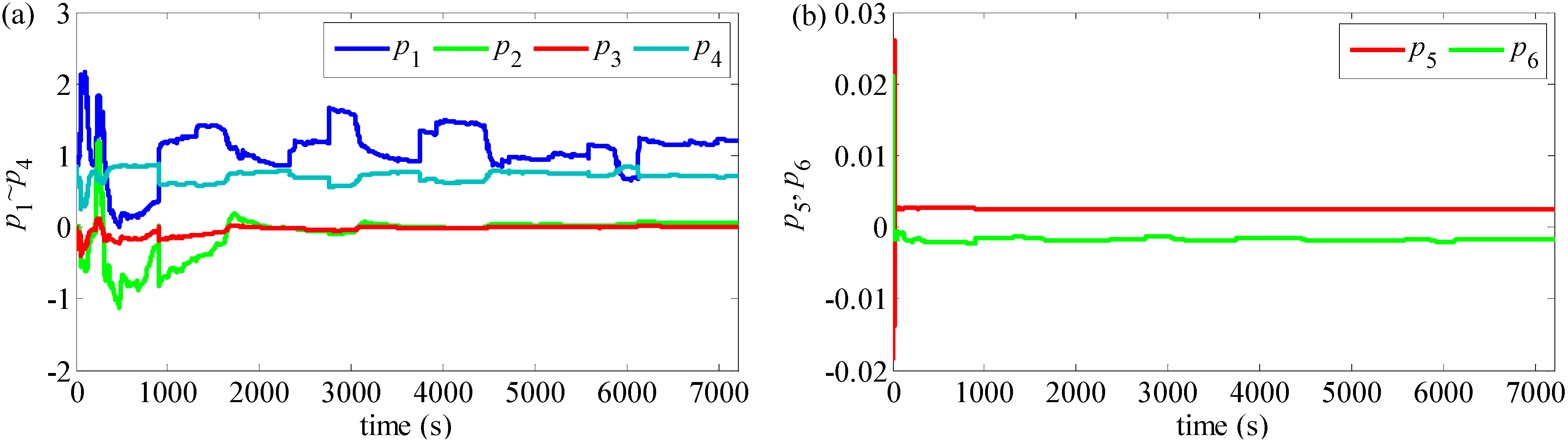
The online parameters identification results for parameter matrix
θk are shown in
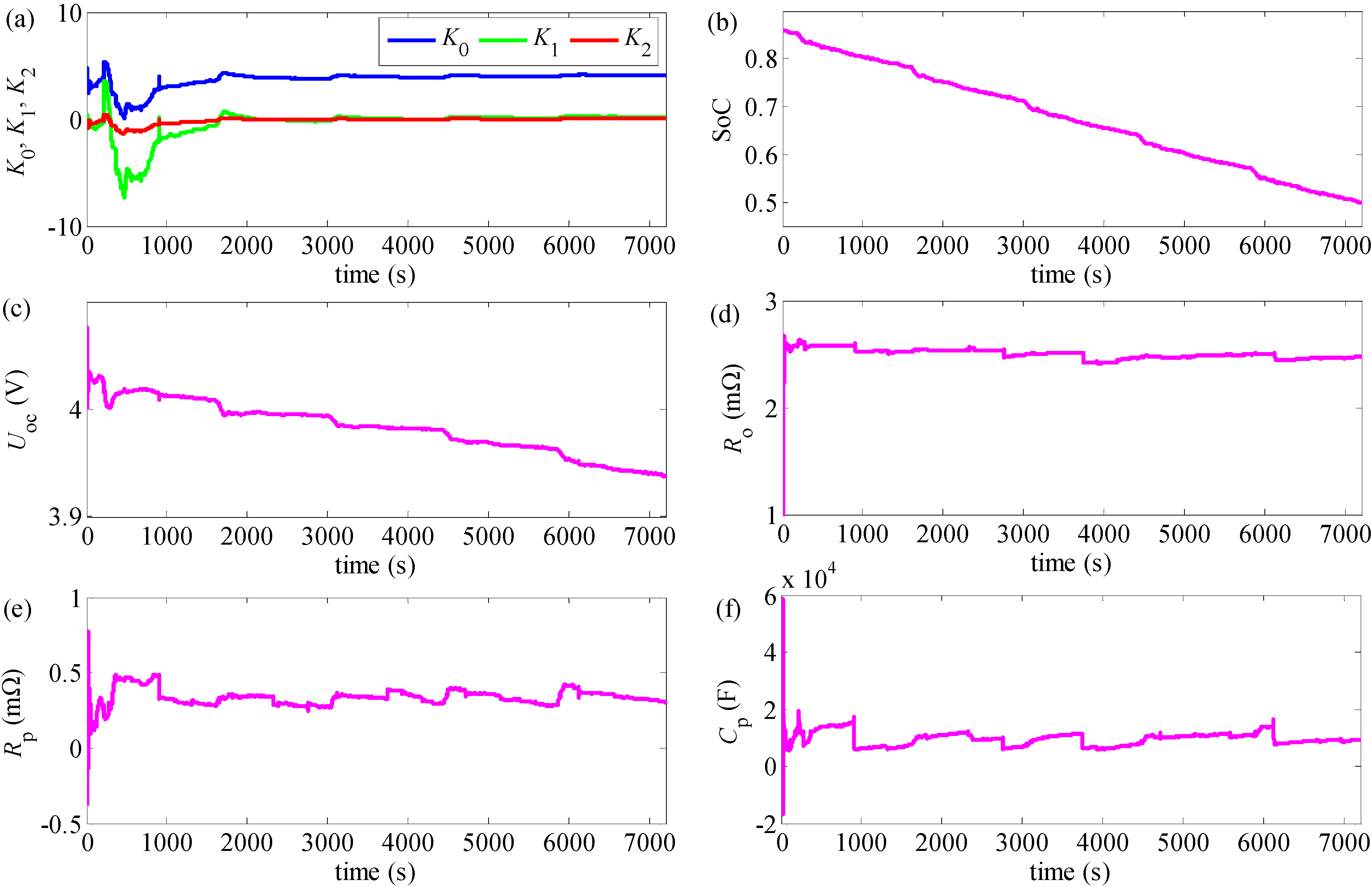
Figure 4. The model’s parameters can be deduced by Equation (13) and the results are shown in
Figure 5.
Figure 4.
The online identification results for parameter matrix θk: (a) p1~p4; (b) p5 and p6.
Figure 4.
The online identification results for parameter matrix θk: (a) p1~p4; (b) p5 and p6.
Figure 5.
Online parameters identification results of the EP model and calculated SoC profiles: (a) K0, K1, K2; (b) Calculated SoC; (c) Uoc; (d) Ro; (e) Rp; (f) Cp.
Figure 5.
Online parameters identification results of the EP model and calculated SoC profiles: (a) K0, K1, K2; (b) Calculated SoC; (c) Uoc; (d) Ro; (e) Rp; (f) Cp.
Then we can evaluate, for the online parameters identification method, the accuracy of the estimated terminal voltage.
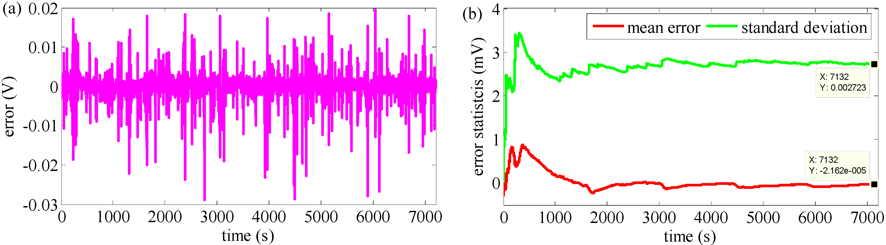
Figure 6 shows the online estimated terminal voltage error and its statistical information. In
Figure 6(a), it is shown that with the RLSF-based online parameters identification approach, good accuracies can be obtained with the maximum estimated voltage error being smaller than 0.03V (within 1% of its nominal voltage which is 0.037 V), which suggests the EP model has good dynamic performance. The mean estimated error is usually the preferred evaluation index since it takes into account each individual observation and is most amenable to statistical analysis, and
Figure 6(b) shows the maximum mean error is less than 1 mV, and the mean error is not always decreasing as time goes on, but has small amplitude variations, which occur because an accurate estimate depends on the simulation precision of the operating environment and process noise, the proposed online identification algorithm requires update the estimates and decrease the estimation errors continuously.
Figure 6.
The comparison profiles of the terminal voltages: (a) The voltage error between the measured value and the online estimated value; (b) Error’s statistical information.
Figure 6.
The comparison profiles of the terminal voltages: (a) The voltage error between the measured value and the online estimated value; (b) Error’s statistical information.
The mean error of estimated voltage is near zero, which indicates the feasibility of the online parameter identification method. Further,
Figure 6(b) shows the standard deviation of estimated error which is a measure of how spread out the observation values is, which is less than 3.7 mV, which enhance the evidence of the efficiency and the reliability performance of the proposed approach. More importantly, the errors converge to the measured value quickly, which indicates the accuracy of the EP model is enough for other battery calculation algorithms, and the RLSF algorithm has better predictive abilities of the uncertain variables if the time-consuming experiments for periodical parameters calibration are avoided.
The real-time peak power capability and current estimation results are shown in
Figure 7.
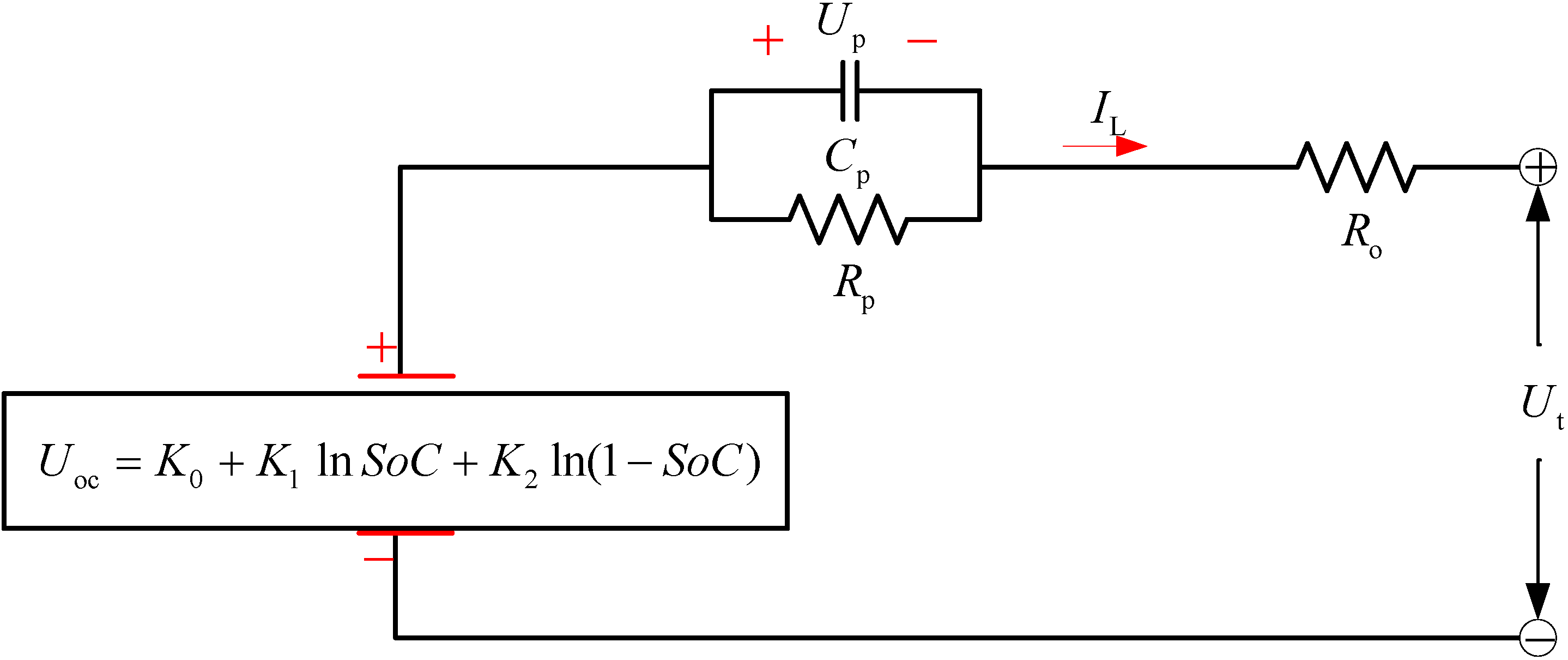
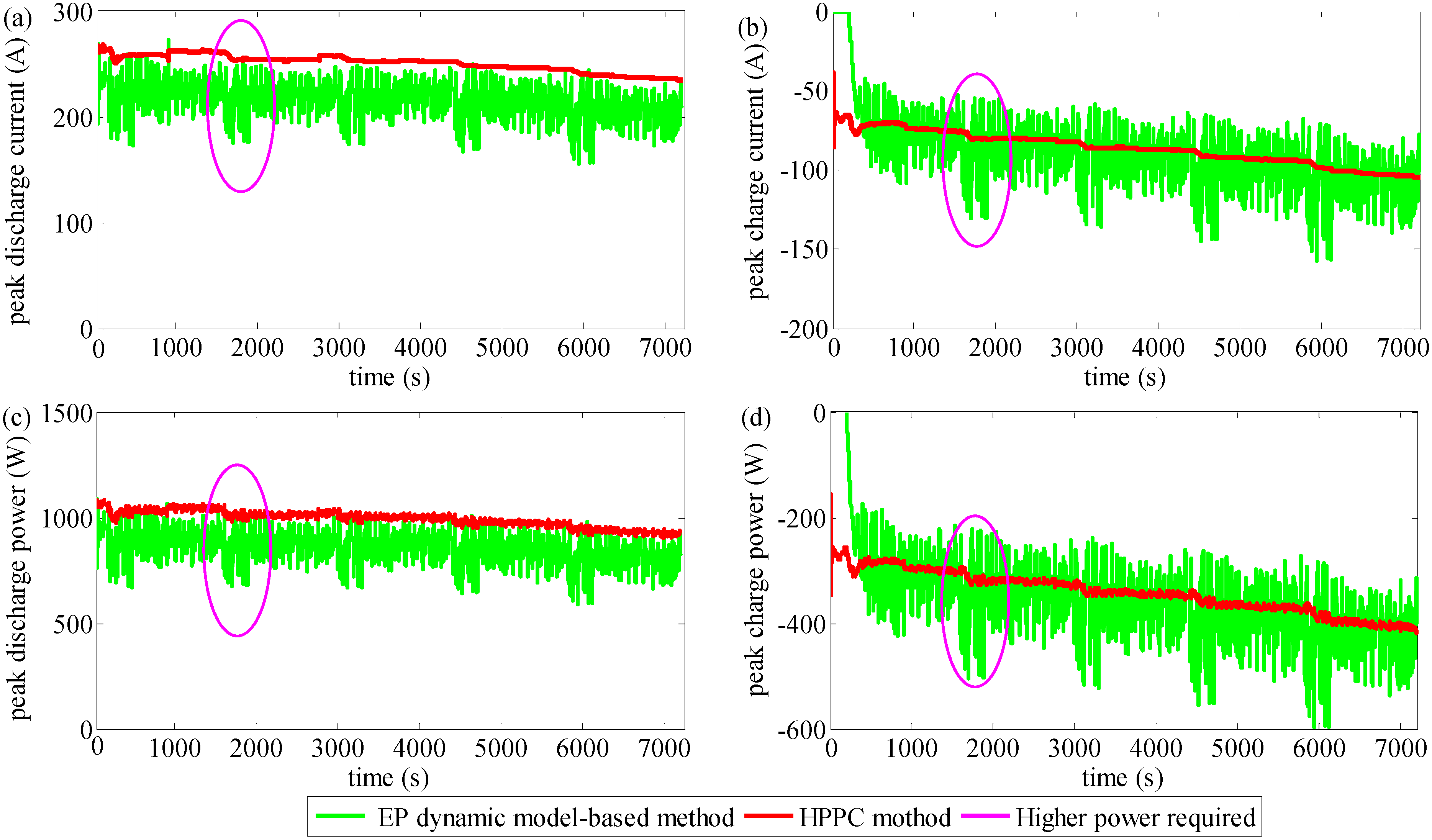
Figure 7(a) shows that the peak discharge current calculated with the HPPC method is higher than with the EP dynamic model-based method. A notable feature of the EP dynamic model-based method is that it takes the entire ∂
Uoc/∂s > 0 of the cell into account when making a prediction while the former doesn’t. For ∂
Uoc/∂s > 0, which leads to a lower peak discharge current value in contrast to the values of the HPPC method, the result is a more realistic representation. Further, the EP dynamic model can simulate the dynamic effect of lithium-ion batteries well, while the
Rint model fails to do this. When discharging,
Up > 0, it is obvious that the current based on the
EP model is lower, especially in the ranges of high required power. The estimated peak current with the proposed peak power capability estimation decreases quickly because the polarization voltage increases quickly.
Figure 7(b) shows the peak currents with the EP dynamic model-based method, which, considering the lithium-ion battery relaxation effect is well simulated, can meet the actual performance well. If the SoC value reaches the maximum design limit, the peak charge current will be very small while the peak discharge current will be very big. On the contrary, if the SoC value reaches the minimum design limit, the peak discharge current will be very small while the peak charge current will be very big. As a result, the method can optimize the operation range of batteries and extend their lifespan. At the same time, when the battery is being discharged with big currents, the peak discharge value is reduced significantly while the peak charge capability is significantly increased. This is conforming to the actual battery working characteristics and underlying optimization control.
Figure 7.
Peak power capability and current online estimation results: (a) Peak discharge currents; (b) Peak charge currents; (c) Peak discharge powers; (d) Peak charge powers.
Figure 7.
Peak power capability and current online estimation results: (a) Peak discharge currents; (b) Peak charge currents; (c) Peak discharge powers; (d) Peak charge powers.
Figure 7(c) shows that the peak discharge power calculation with the HPPC method is obviously higher than the calculation with the proposed method. This is because the HPPC method only considers the battery voltage constraints, neglecting the constraints of the cell current, SoC and power. Furthermore this method gives an optimistic estimation and may lead to over-discharging. A notable feature of the proposed new method is that it takes the entire dynamics of the cell into account when making real-time estimations. The strong discharges at the high required power ranges pull the cell’s terminal voltage down, allowing less discharge power than with the HPPC method. So the HPPC method overpredicts the charge power at high SoC. However, the biggest problem of the HPPC method comes from ignoring the SoC design limits. It also overpredicts power when a continuous big current is required, while it ignores the dynamic performance from the polarization voltage
Up. The two methods are also compared with respect to charging power, as shown in
Figure 7(d). Due to the ignorance of the SoC limits and the relaxation effect of the battery, the HPPC method is prone to overpredicting the charging power. With strong discharges at high required power ranges, the battery will allow a greater charging power while the HPPC method cannot give the accuracy peak power estimates quickly to match the driving cycle changes. However, the real-time peak power capability estimation results with the EP dynamic model-based method are not flat due to the polarization effects. Therefore the proposed method for peak power capability estimation gives satisfying results.
Overall, the HIL test suggests that the proposed online peak power capability estimation is reliable, and can give more accurate estimation results than the traditional methods. Furthermore, the online parameter identification method can ensure the performance of the EP dynamic model. More importantly, the proposed peak power capability estimation can be applied at electric vehicles without requiring a periodical calibration for ensuring the model’s accuracy.


