Article

Exergoeconomic Evaluation of a Modern Ultra-Supercritical Power Plant

School of Energy, Power and Mechanical Engineering, North China Electric Power University, Beinong Road 2, Beijing 102206, China
*
Author to whom correspondence should be addressed.
Energies 2012, 5(9), 3381-3397; https://doi.org/10.3390/en5093381
Submission received: 21 June 2012 / Revised: 3 August 2012 / Accepted: 21 August 2012 / Published: 6 September 2012

Abstract

:
In this paper, the exergoeconomic analysis was conducted to an existing ultra-supercritical coal-fired power plant in China to understand the cost-formation process, to evaluate the economic performance of each component and to find possible solutions for more cost-effective designs. The total revenue requirement (TRR) and the specific exergy costing (SPECO) methods were applied for economic analysis and exergy costing, respectively. Quantitative balances of exergy and exergetic costs as well as necessary auxiliary equations for both individual component and the overall system were established. The results show that the exergoeconomic factors of the furnace and heat exchangers at low temperature levels, including air preheater and low-pressure feedwater preheaters, are rather small; while those of other components are relatively large. Moving more heat absorption into furnace to use the effective radiation heat transfer, increasing the air preheating temperature and adding more low pressure feedwater preheaters can be promising solutions for future design.

1. Introduction

In order to fulfill the objectives of a 20% reduction of national gross fuel consumption and a 10% reduction of total emission of mean pollutants during 2005 to 2010 [1], the efficiency improvement of coal-fired power plants, still contributing over 83% of China total power generation [2], became the first priority and called for a structure adjustment of the electricity generation industry in China.
In 2006, the coal-fired power plants less than 100 MW in China reached a total installed capacity as high as 125 GW with the annual coal consumption and SO2 emission more than 400 and 5.4 million tons, respectively [3]. The pursues for higher efficiency, more economic benefits and lower pollutant emissions lead to the gradual phase-out of the small-scale backward power plants, which are replaced by advanced supercritical and ultra-supercritical ones with higher steam parameters [4].
In order to safely use higher temperature steam over 600 °C, more demanding requirements, especially in terms of advanced materials with higher allowed temperature and pressure, higher resistance to steam oxidation corrosion, better welding performance and larger heat conduction coefficient, largely increase the associated capital and maintenance costs of both boiler and turbine. It is apparent that the research on new material is the key factor for the development of supercritical and ultra-supercritical technologies. With lots of pioneer plant practices, the ferrite/martensite steels, mainly P91, P92, E991 and P122, have been the primary choices for high temperature materials for live steam pipelines; the austenitic steels such as HR3C and SUPER304H are commonly used for the high temperature heat surfaces [5]; Ni-based forging steel is currently selected as the material of rotary blades of high pressure turbine stages. In 2009, compared with the price of high temperature steel of subcritical power plants ranging from $15,000~18,000/ton, the specific cost of the four ferrite/martensite steels for supercritical and ultra-supercritical technologies is within the range of $20,000~30,000/ton [6]. The investment distribution of newly built modern power plants may be different from the subcritical ones and, therefore, has some influences on the cost formation process.
The exergoeconomic analysis is a powerful tool for evaluation and optimization of various energy systems by calculating the cost rates of each material and energy stream, and the component-related exergoeconomic variables. The term exergoeconomic was first introduced by Tsatsaronis [7] as an accurate and unambiguous characterization of a combination of economics and the exergy concept, and this methodology was greatly developed and applied with the contribution of many researchers including Valero and Lazano [8,9], Frangopoulos [9,10], von Spakovsky [11], Lazzaretto [12,13], Tsatsaronis [14,15,16,17,18,19,20] and some co-work [21,22,23] etc. Recently, there were also many applications of exergoeconomics for improving various power plants. Ahmadi et al., performed comprehensive exergy, exergoeconomic and exergoenvironmental impact analysis and multi-objective optimization to a cogeneration plant system [24], combined cycle power plants [25], a gas turbine power plant [26], with exact expressions of cost functions of each component and the cost expenditure due to pollutant and greenhouse gas emissions. Petrakopoulou [27] conducted the exergoeconomic and exergoenvironmental analysis on a newly-proposed chemical looping power plant and also combined an iterative optimization to reduce the cost and environmental impacts. Shamsi [28] optimized the steam pressure levels in a total site using thermoeconomic method and reached a total cost reduction of up to 8%.
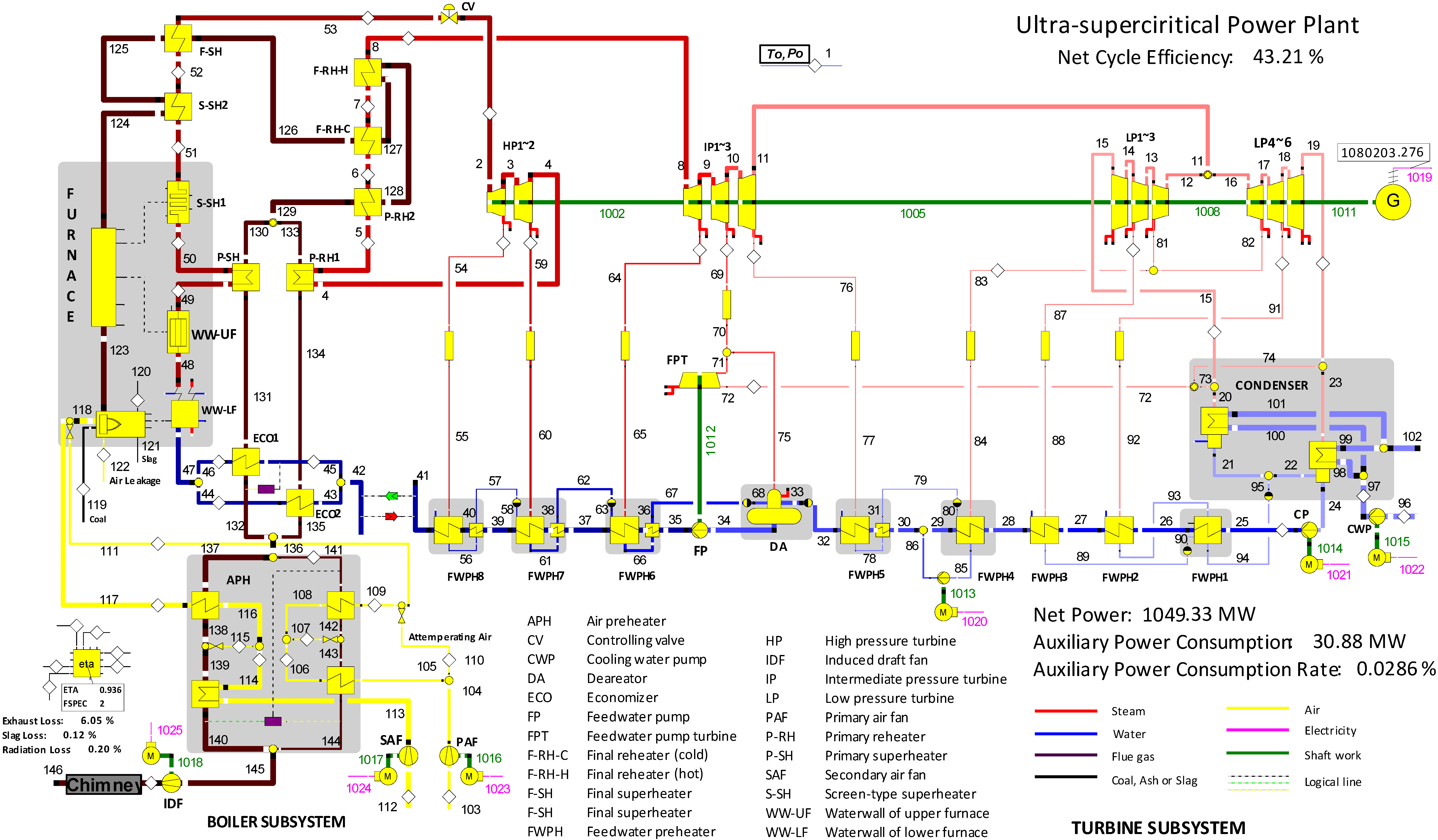
Although the exergoeconomic analysis has been widely applied for analysis and optimization of power plants, seldom focuses on the modern ultra-supercritical large-scale coal-fired power plants, where the insights into the exergoeconomic performances of the subcomponents of the once-through boiler are needed. In this paper, an existing ultra-supercritical power plant designed in 2006, constructed in 2008 and operated in 2010, was modeled and analyzed from the exergoeconomic viewpoint by using the SPECO method [22]. In this regard, the specific objectives of this paper are as follows:
  • To model the thermodynamic performance of the whole power plant and to obtain the basic information for cost estimation of the power plant.
  • To perform detailed thermodynamic calculation for the design of boiler.
  • To combine the standard design method of boiler with the corresponding economic analysis and to generate an equivalent approach to estimate boiler cost as the so-called cost function.
  • To identify the cost-formation process, evaluate each component and provide some useful information for the future design improvement.

2. Exergoeconomic Analysis

The exergoeconomic analysis combines an exergetic analysis with an economic analysis to provide crucial information that is not obtainable through conventional thermodynamic analysis and simple exergy analysis or economic analysis [17]. With reasonable exergy costing method, the specific cost related with each exergy stream and the exergoeconomic variables are computed to provide some valuable information for a cost-effective enhancement by pinpointing the required changes in structure and parameter values [16,29]. A complete exergoeconomic analysis generally consists of an exergy analysis, an economic analysis and then an exergy costing method with the help of auxiliary equations.

2.1. Exergy Analysis

An exergy analysis identifies the location, the magnitude and the sources of thermodynamic inefficiencies in an energy system. By calculating chemical and physical exergy of each stream, the application of exergy analysis is quite straightforward with the calculation of exergy destruction within each component E ˙ D , k and the corresponding exergetic efficiency εk and exergy destruction ratio yD,k:
ε k = E ˙ P , k E ˙ F , k = 1 E ˙ D , k E ˙ F , k
y D , k = E ˙ D , k E ˙ F , t o t
where the E ˙ P and E ˙ F are the product exergy and fuel exergy of kth component (subscript k) and the whole system (subscript tot).
Combining the exergy balance equation of each component and the overall system, the detailed exergy destruction and loss rate, and overall exergetic efficiency can be obtained which can provide useful information for improvement from thermodynamic point of view:
ε t o t = E ˙ P , t o t E ˙ F , t o t = 1 E ˙ L , t o t + k = 1 N C E ˙ D , k E ˙ F , t o t
where E ˙ L , t o t means the exergy loss of the whole system while NC indicates the number of components.
Two points [16,22] should be emphasized in the exergy analysis are: (a) the dissipative components such as gas cleaning units and throttling valves as well as condensers without any thermodynamic benefits when considered in isolation cannot be assessed by the exergetic efficiency, and (b) the exergy loss are defined unambiguously as the transportation of exergy from the overall system to its surroundings which means that when no exergy loss term appears in the exergy balance equation at a component level.
It should be noted that the chemical exergy of mixtures such as flue gas is defined as follows [17]:
e m i x c h = [ i = 1 n X i e c h i + R T 0 i = 1 n X i l n ( X i ) ]
where n, X, ech, R and T0 represent the composition number of the mixture, the molar fraction of each composition, the specific chemical exergy of each composition, universal gas constant and the reference temperature, respectively.
The fuel exergy of fuel (ef) is evaluated by the following exergy ratio ξ:
e f = ξ · H H V
where HHV means the higher heating value of coal and ξ for coal can be taken as 1.04 [17].

2.2. Economic Analysis

The annual values of capital-related charges (carrying charges), fuel cost and operating and maintenance expenses vary significantly within the plant economic life. Thus, levelized costs are need for the evaluation and cost optimization of an energy system. The TRR method [27] was applied based on the good estimation of the purchased equipment cost (PEC) and fixed capital cost FCI (FCI = PECFBM and FBM is the bare module factor), and cost escalation to the reference year in accordance with Chemical Engineering Plant Cost Index (CEPCI). At last, the levelized cost rates associated with the kth component ( Z ˙ k C I , Z ˙ k O M and Z ˙ k ) and levelized fuel cost (cF) can be obtained by Equations 6–9 as the input variables for exergoeconomic analysis:
Z ˙ k C I = C C L τ P E C k n P E C n
Z ˙ k O M = O M C L τ P E C k n P E C n
Z k ˙ = Z k C I ˙ + Z ˙ k O M
c F = C F L τ
where τ represents the equivalent working hours at full load.

2.3. Exergy Costing and Auxiliary Costing Equations

The specific cost (ci) associated with each material and energy stream i is computed according to exergy costing and auxiliary costing equations, for which Lazzaretto and Tsatsaronis [22] proposed a systematic and general methodology (SPECO) with an explicit matrix form of these equations.
After clearly identifying each exergy stream, the exergy costing can be expressed by four exergy-based monetary costing Equations 10–12 and the cost balance (Equation 13) for each component:
C ˙ i = c i E ˙ i = c i m ˙ i e i
C ˙ w = c ˙ w W ˙
C ˙ q = c q E ˙ q
e ( c e E ˙ e ) k + c w , k W ˙ k = c q , k E ˙ q , k + i ( c i E ˙ i ) k + Z ˙ k
where W, Q, C ˙ w and C ˙ q mean work, heat and cost rates of work and heat, respectively. The subscripts e and i indicate the exiting and inlet streams.
On the basis of F and P principles, totally (Ne − 1) auxiliary equations are required to determine the specific costs of products associated with the each component. The F principle states that the specific cost (cost per exergy unit) associated with this removal of exergy from a fuel stream must be equal to the average specific cost at which the removed exergy was supplied to the same stream in upstream components. While The P principle states that each exergy unit is supplied to any stream associated with the product at the same average cost. Combining the cost balance equations and the corresponding auxiliary equations, the explicit matrix can be straightforwardly solved by gaussian elimination and, therefore, the specific cost of each stream, the cost of thermodynamic inefficiency of each component and the related exergoeconomic variables can be obtained.
For the dissipative components, including the condenser and throttle valves in this case, the fictitious cost rates C ˙ d i f f , d c must be calculated by Equation 14 based on their cost balance and the auxiliary equations in accordance with the F principle (ce = ci), and then apportioned to the cost of the final product of the overall system:
C ˙ d i f f , d c = i c i E ˙ i + C ˙ a u x + Z ˙ d c
where C ˙ a u x indicates the cost rate of additional working fluid and Z ˙ d c means the captital investment of dissipative components.
The costing of exergy loss exiting the kth component is referred to the F principle of the kth component. If no special treatments such as gas cleaning are conducted before the material stream is rejected to the environment, the cost rate of the exergy loss can be calculated by Equation 15:
C ˙ L = c F , k E ˙ L

2.4. Exergoeconomic Variables

The average unit cost of fuel cF,k and product cP,k, the cost rate of exergy destruction C ˙ D , k , the sum of C ˙ D , k and Zk, the relative cost difference rk and exergoeconomic factor fk are known as the thermoeconomic variables [29], among which rk and fk are the most important two exergoeconomic variables to rank the components based on their individual performance. The relative cost difference rk is expressed as the difference between the specific cost of the product cP,k and the fuel cF,k:
r k = C ˙ P , k C ˙ F , k C ˙ F , k = 1 ε k ε k + Z ˙ k C ˙ D , k
The cost added to an exergy stream due to the thermodynamic inefficiency within one component can be evaluated by the component exergoeconomic factor, through which the monetary impact of exergy destruction and capital investment of each component can be revealed:
f k = Z ˙ k Z ˙ k + C ˙ D , k

3. Plant Description, Simulation and Cost Estimation

3.1. Plant Description

The single-reheat ultra-supercritical coal-fired power plant with total capacity 1000 MW comprises a Π-type once-through boiler, a condensing turbine, a generator as well as other auxiliary components and systems. The schematic and basic data of the reference plant are presented in Figure 1 and Table 1, respectively. The composition of the bituminous coal for the design is listed in Table 2.
Table 1. Basic data of the power plant.
Steam Cycle Data (100% Load)
Main steam861.6 kg/s (274 bar, 605 °C)
Reheat steam715.6 kg/s (56.8 bar, 603 °C)
Condenser pressure0.052 bar
Gross power output1100 MWe
Net power output1070 MWe
Auxiliary power consumption30 MWe
Net efficiency44.15%
Table 2. Coal composition.
Ultimate Analysis (wt %; as Received)
Carbon57.37%
Hydrogen4.19%
Oxygen7.57%
Sulphur0.87%
Nitrogen1.4%
Moisture21.3%
Ash7.3%
LHV (kJ/kg)22,000
Figure 1. Diagram of the reference ultra-supercritical power plant with detailed description of all components related to exergoeconomic analysis.
Energies 05 03381 g001
Advanced combustion mode and devices, and reliable heat surface configuration with proper adjustment method for steam temperature are applied to guarantee high availability, good economic performance, reasonable dimension and heat flux of the furnace. After perheating, the feedwater first enters the two economizers (ECOs) placed in the front and back parts of rear flue gas duct, and then passes through the water wall (WW), one primary superheater (P-SH), two screen-type superheaters (S-SH1 and S-SH2) and one final superheater (F-SH) to generate live steam. The cold reheat steam coming from the exhaust of intermediate pressure turbine (IP) flows through the primary reheater (P-RH1 and P-RH2) and the final reheater (F-RH-H and F-RH-C). The temperature adjustment of reheat steam is based on the opening adjustment of the damper placed in the rear flue gas duct; while that of the live steam is mainly based on spray attemperators. Two Ljungström air pre-heaters (APHs) are configured to preheat the air by recovering low grade heat of flue gas.
The ultra-supercritical turbine is of a classical condensing configuration with four cylinders and four exhausts to enlarge the unit capacity. The feedwater regenerative system is composed of three high-pressure heaters, a deaerator and four low-pressure heaters to heat the feedwater to 300 °C. Large power consumption of feedwater pumps is supplied by the corresponding secondary condensing turbine. It is noted that the condenser is a dual-pressure one with two shells.

3.2. Plant Simulation

The power plant was modeled and simulated with the key features of each component or process, shown in Table 3 by Ebsilon Professional. The thermodynamic data for the selected streams are presented in Table 4. The heat transfer between auxiliary heat surfaces and the flue gas is neglected due to the small increase of steam temperature. The total outgoing flue gas of the furnace is assumed to pass the first screen-type superheater with the heat also absorbed by the auxiliary water wall, and then pass the second screen superheater. The air preheater is modeled in detail with the exact leakage air and attemperating air. The sealing steam leakage of turbine cylinders and the feedwater preheater using these leakage steams are omitted due to small mass flow rates of these steams and the small temperature increase of feedwater, respectively.
Table 3. Key features for different components or processes.
NameSpecification aNameSpecification b
Combustionα = 1.2; Δpfg = 100 Pa; ηc = 1; tslag = 600 °CIP2ηs = 0.915; ηm = 0.998
WWΔpwf = 20.9 bar; Qt = 1104 MWIP3ηs = 0.929; ηm = 0.998
P-SHΔpwf = 3.8 bar; Qt = 185 MWLP1ηs = 0.912; ηm = 0.998
S-SH1Δpwf = 4.2 bar; Qt = 151 MWLP2ηs = 0.919; ηm = 0.998
S-SH2Δpwf = 4.8 bar; Qt = 138 MWLP3ηs = 0.835; ηm = 0.998
F-SHΔpwf = 5.0 bar; Qt = 133 MWLP4ηs = 0.912; ηm = 0.998
F-RH-CΔpwf = 1.7 bar; Qt = 129 MWLP5ηs = 0.914; ηm = 0.998
F-RH-HΔpwf = 2.0 bar; Qt = 44.8 MWLP6ηs = 0.788; ηm = 0.998
P-RH2Δpwf = 2.5 bar; Qt = 45.1 MWGηs = 0.99; ηm = 0.998
P-RH1Δpwf = 2.5 bar; Qt = 177 MWCONDΔtpinch = 5 K; Δpwf = 0.05 bar
ECO1Δpwf = 1.0 bar; Qt = 86.9 MWFPTηs = 0.81; ηm = 0.998
ECO2Δpwf = 1.0 bar; Qt = 61.5 MWFWPH1Δtlow = 5.6 K; Δpfw = 0.54 bar
APHΔppa = 420 pa; Δpsa = 2600 Pa;FWPH2~4Δtup = 2.8 K; Δpfw = 0.54 bar
mL,pa→fg = 39.7 kg/s; mL,pa→fg = 9 kg/sFWPH5Δtup = 2.8 K; Δtlow = 5.6 K; Δpfw = 0.54 bar
Qt,pa = 38 MW; Qt,sa = 236 MWDAP = 0.7 bar
IDFηs = 0.87; ηm = 0.99FWPH6~7Δtup = 0 K; Δtlow = 5.6 K; Δpfw = 1.12 bar
SAFηs = 0.88; ηm = 0.99FWPH8Δtup = −1.7 K; Δtlow = 5.6 K; Δpfw = 1.11 bar
PAFηs = 0.875; ηm = 0.99FPηs = 0.84; ηm = 0.998
HP1ηs =0.869; ηm = 0.998CPηs = 0.87; ηm = 0.998
HP2ηs = 0.925; ηm = 0.998CWPηs = 0.8; ηm = 0.998
IP1ηs = 0.894; ηm = 0.998Motorsη = 0.97; ηm = 0.998
a α–air ratio; Δpfg—pressure drop of flue gas; ηc—combustion efficiency; tslag—slag temperature; Δpwf—pressure drop of working fluid; Qt—heat transferred in this component; Δppa—pressure drop of primary air; Δpsa—pressure drop of secondary air; mL,pa→fg—air leakage from primary air to flue gas; mL,sa→fg—air leakage from secondary air to flue gas; ηs—isentropic efficiency; ηm—mechanical efficiency; b Δtpinch—pinch point; Δtlow—low terminal temperature difference; Δtup—upper terminal temperature difference; Δpfw—pressure drop of feedwater.
Table 4. Thermodynamic data for selected streams.
IDmtpEchEIDmtpEchE
kg/s°CbarMWMWkg/s°CbarMWMW
2861.6601.4262.52.151408.237861.6221.9316.232.15205.8
3816.3420.986.312.041072.639861.6279.4315.112.15306.1
4715.6380.365.561.79888.141861.6299.93142.15347.7
5715.6476.063.061.79987.247861.6332.03132.15421.8
6715.6501.060.561.791011.249861.6441.0292.12.151038.7
7715.6577.058.861.791091.350861.6476.0288.32.151148.2
8715.6603.056.861.791117.651861.6515.0284.12.151240.5
9679.9472.024.791.70871.252861.6558.0279.32.151327.0
10601.6370.712.181.50644.053861.6605.0274.32.151412.7
11564.8289.76.4901.41511.37249.936.80.0620.126.4
13282.4289.76.4900.65185.3104231.532.11.1440.462.9
14262.0192.92.6770.59110.7111191.8200.01.140.3910.0
15236.990.10.7040.5923.7113746.024.41.0581.504.4
17236.933.60.0520.71255.7117737.0336.01.0311.4879.8
18282.4289.76.4900.65185.31241047.51139.80.99855.95888.6
19262.0192.92.6770.5974.81251047.51037.80.99855.95780.1
24573.933.60.0521.432.11261047.5938.20.99855.95677.7
25573.933.716.081.433.01271047.5839.90.99855.95580.8
26573.937.115.541.433.41281047.5805.50.99855.95547.9
27573.962.415.001.439.01291047.5770.80.99855.95515.2
28573.985.914.461.4317.7131575.1503.60.99830.72158.1
30651.5125.513.921.6344.7134472.4456.70.99825.23114.2
32651.5158.313.381.6371.51361047.5358.90.98355.95185.9
34861.6185.811.432.15129.81451096.2119.20.97254.4069.8
35861.6192.4317.322.15162.61461096.2128.51.04954.4079.4

3.3. Cost Estimation

The power plant was designed for a 25-year economic life with an average interest rate 10%, average nominal escalation rates 3.5% for fuel (coal) and 3% for other costs and could operate for 6900 h/year at a load capacity 80%. The average price of the coal with the LHV of 29,270 MJ/kg was $84.3/ton (2.88 $/GJ-LHV) in 2009. It means the levelized FC reaches as high as $196.5 million.
The PEC of the entire sets of the once-through boiler, including the air preheaters, high pressure and low pressure regenerative heaters, the steam turbine and other separate components, could be obtained from [6]. The PEC of boiler and steam turbine needs to be apportioned to their sub-components shown in Figure 1. It is noted that the PEC of rotary air preheaters comprises approximately 2% of PEC of the boiler body [30], which means the boiler subsystem excluding SAF, PAF as well as IDF. The allocation of the remaining PEC of boiler is on the basis of Table 5, where the main material, average tube size, total tube surface area and weight are presented. Owing to the lack of information for the specific costs for different types of steel, weighting factors for each heat exchanger in boiler are assumed in accordance with properties of their material, while the allocation of turbine PEC is weighted based on both the power output and the pressure level of each sub-component with the weighting factors 1, 1.5 and 2 for HPs, IPs and LPs, respectively.
Table 5. Information of heat surfaces in the once-through boiler.
NameMaterialTube Size δ × roTube Surface Area (m2)Weight *Weighted Factor
(mm × mm)(ton)
FURWW-S15CrMoG38.1 × 78,880406.771.0
WW-V12Cr1MoVG31.8 × 74,603207.241.0
S-SH1T91, S304H41.3 × 73,308143.663.0
S-SH2S304H47.7 × 102,880180.443.0
F-SHS304H, HR3C44.5 × 104,105252.273.0
F-RH-CS304H, HR3C57 × 65,916233.113.0
F-RH-HS304H, HR3C57 × 62,843112.023.0
P-RH2T9163.5 × 53,305109.571.5
P-SH12Cr1MoVG, T9146.1 × 625,1061038.821.0
ECON1SA-210C50.8 × 914,190833.250.8
P-RH112Cr1MoVG, T9163.5 × 525,137833.381.0
ECON2SA-210C50.8 × 920,1121180.990.8
* Equation for steel weight is [0.02491 ∙ δ ∙ (roδ) ∙ L]/1000(ton), where units of δ, r, L should be m.
The module factors for different types of components to calculate the FCI from their PEC are referred to [31] and listed in Table 6. With the ratio of component PEC to the total PEC, the levelized CC and OMC can be readily apportioned to each component. The TCI estimation for the whole power plant is around $828 million, which means the specific cost of the power plant is nearly $774/kW.
The levelized CC, OMC and FC contribute 30%, 7% and 63% to the TRR $308 million/year, meaning that the price of the final product is 5.22 cent/kWh. It agrees quite well with the on-gird electricity price of 5.20 cent/kWh announced by the power plant [32].
Table 6. FBM for different types of components [31].
NameFBMNameFBM
Fired heaters and furnace2.8Other heaters1.7
Main turbine6Drive turbine for pumps3.7
Fans2.8Pumps1.3
Generator1.7

4. Results and Discussion

Table 7 presents the results of the exergetic and exergoeconomic analysis for two conditions: with and without Zk. Comparisons of the cost rates associated to each component enable us to understand how the cost structure or cost formation process changes after adding the capital, operation and maintenance investments.
The exergetic analysis reveals the location, magnitude and sources of exergy destruction. Chemical reaction and heat transfer process are always the largest sources of entropy generation in energy systems. It is shown that the exergy destruction in furnace has far larger exergy destruction than any other components, resulting in the lowest exergetic efficiency of 62.8%. The performance of other heat exchangers in boiler improves greatly with the decrease of average temperature difference for the heat transfer between the hot and cold fluids. The turbine stages except ones working within the range of wet steam have higher exergy efficiency (generally over 90%) than heat exchangers. The exergetic performances of regenerative feedwater preheaters improve with the increase of feedwater temperature level. The exergetic efficiency of the last preheater reaches as high as 96.4%. It should be noted that the exergetic efficiencies of air preheater, the first and second feedwater preheaters are far less than those of other heat exchangers, due to the low temperature level of their cold fluids. In addition, the auxiliary components, mainly pumps and fans here, are regarded to have relative high efficiency around 85%.
It is very clear from the exergoeconomic analysis with Zk = 0 that the specific costs of the flue gases remain unchanged due to the F principles for boiler sub-components and the specific cost of the intermediate product accumulates gradually among the components towards the final product. Due to this accumulation, the distribution of hidden costs caused by the exergy destructions among different components tends to be quite different from that of their exergy destructions. The exergy destruction within boiler components excluding the furnace reaches as high as 150 MW which is almost two times more than that of turbine itself (82 MW); however, their hidden cost rates are proven to be almost the same with $2,180/h and $2,045/h for boiler and turbine, respectively. It indicates that the economic importance of exergy destruction within a component depends highly on its relative position of the component with respect to fuel and product streams of the overall system [27].
The sum C ˙ D , k + Z ˙ k indicates the cost importance of different components and the improvement of design should be initially focused on the components with higher C ˙ D , k + Z ˙ k . From this point of view, the once-through boiler, among which almost all the sub-components, especially the furnace, have very large C ˙ D , k + Z ˙ k , and the components HP1, IP1 and LP6 of the turbine are the keys for improving initial design of the power plant.
Table 7. Results of the exergetic and exergoeconomic analysis for selected components of the reference power plant.
NameExergy Balance Z k = 0 Z k 0
E ˙ D E ˙ F E ˙ P yDεkcfcpr C ˙ D cfcp C ˙ D Z ˙ C ˙ D + Z ˙ rf
MWMWMW%%$/GJ$/GJ-$/h$/GJ$/GJ$/h$/h$/h--
Boiler BodyFUR944.22542.0159737.3362.864.0806.4910.5913,8694.1436.8721,40821,615.315,6970.660.10
Boiler SubsystemS-SH222.0108.586.50.8779.704.0185.0410.26318.74.0187.728318.7836.71,155.40.920.72
F-SH16.7102.485.70.6683.724.0184.8000.19241.14.0188.592241.11,169.81,410.91.140.83
F-RH-C16.997.080.10.6782.604.0184.8650.21244.14.0188.614244.11,081.01,325.01.140.82
F-RH-H6.532.926.30.2680.184.0185.0120.2594.24.01810.49094.2519.5613.71.610.85
P-RH28.732.724.00.3473.454.0185.4700.36125.54.0188.409125.5254.1379.61.090.67
P-SH19.1118.299.10.7683.844.0184.7920.19276.24.0189.295276.21,605.71,881.91.310.85
ECON115.3124.8109.50.6087.764.0184.5780.14220.94.0187.192220.91,030.41,251.20.790.82
P-RH14.537.533.10.1888.104.0184.5610.1464.64.01815.37964.61,288.21,352.82.830.95
ECON27.648.641.00.3084.284.0184.7670.19110.64.01814.662110.61,460.41,571.02.650.93
APH33.5116.182.51.3371.114.0185.6510.41485.14.0186.397485.1221.7706.70.590.31
PAF0.52.92.50.0284.308.3609.9170.1913.812.87330.23421.3132.9154.21.350.86
SAF0.53.42.90.0284.508.3609.8940.1816.112.87326.34024.7116.3141.11.050.83
IDF1.611.29.60.0686.028.3609.7180.1647.012.87320.65372.3196.6268.90.600.73
Turbine SubsystemTurbine BodyHP117.2276.1258.80.6893.768.1858.7290.07507.710.87512.182674.6542.91,217.40.120.45
HP22.259.657.30.0996.298.1858.5000.0465.110.87511.87786.5120.3206.70.090.58
IP19.4200.6191.20.3795.317.5137.8820.05254.410.51111.902355.9601.5957.40.130.63
IP26.1143.5137.30.2495.727.5137.8480.05165.910.51111.854232.1432.0664.20.130.65
IP34.099.495.40.1695.967.5137.8290.04108.610.51111.827151.9300.1452.00.130.66
LP13.355.952.50.1394.047.5137.9890.0690.110.51112.342126.0220.3346.40.170.64
LP24.362.958.60.1793.177.5138.0630.07116.210.51112.446162.6246.0408.60.180.60
LP314.087.073.00.5583.957.5138.9500.19377.610.51113.686528.3306.3834.60.300.37
LP43.355.952.50.1394.047.5137.9890.0690.110.51112.342126.0220.3346.40.170.64
LP57.8101.894.00.3192.307.5138.1400.08212.010.51112.553296.6394.2690.70.190.57
LP610.651.340.80.4279.397.5139.4640.26286.210.51114.405400.4170.9571.30.370.30
COND39.3--1.55-9.900- 1,399.113.851-1,957.41,370.93,328.3-0.41
Regeneration SystemFWPH10.5860.9620.3770.02339.137.51319.2001.5615.810.51127.66822.21.123.31.630.05
FWPH22.68.15.50.1068.267.51311.0070.4769.610.51115.68297.35.6103.00.490.06
FWPH32.010.78.80.0881.707.5139.1950.2253.110.51113.01474.44.779.10.240.06
FWPH44.525.921.40.1882.627.5139.0930.21121.710.51112.787170.35.1175.30.220.03
FWPH53.630.526.90.1488.067.5138.5320.1498.510.51111.992137.85.3143.20.140.04
DA3.129.726.60.1289.567.5838.4670.1284.710.54912.645117.883.1200.90.200.41
FWPH64.547.843.20.1890.517.6298.4280.11124.510.57412.860172.5183.4355.90.220.52
FWPH77.1107.4100.30.2893.358.1858.7680.07210.510.87512.315279.7240.1519.80.130.46
FWPH81.543.241.60.0696.428.1858.4890.0445.610.87512.70360.6213.4274.00.170.78
FPT8.646.738.20.3481.687.5139.1980.22231.510.51115.838323.9407.8731.60.510.56
FP5.438.232.80.2185.889.19810.7110.16178.415.83822.285307.2453.3760.50.410.60
CP0.21.10.90.0184.618.3609.8800.185.112.87330.0927.849.957.71.340.86
CWP2.511.18.60.1077.218.36010.8270.3076.412.87328.245117.6358.2475.81.190.75
G11.71111.51099.90.4698.958.2728.3600.01347.612.28812.873516.31,800.22,316.50.050.78
Total (EL = 175MW)12832529107050.7542.313.9119.2441.3618,0693.91114.51218,06920,29338,3622.710.53
In general, the components in boiler subsystem have much larger relative cost difference rk than other components. The heat surfaces placed in the rear flue gas duct, such as P-RH1 and ECON2, achieve the greatest r as high as 2.8, while ones surrounded by higher-temperature flue gas, such as S-SH2, F-RH, F-SH and P-SH, have relative small r ranging from 0.9 to 1.5. Moreover, this parameter of the components in turbine and regeneration system is below 0.5, mostly around 0.1~0.3. What means by this is that the add costs of exergy streams through the heat surfaces after furnace due to their capital investment are much larger than that of turbine subsystem. By comparison, reducing the construction cost of these heat surfaces while keeping or lowering the level of exergy destruction must be achieved for future boiler design.
Exergoeconomic factors can identify the major cost sources (investment cost or cost of exergy destruction) of each component. It is clear that the air preheater and the furnace have far less exergoeconomic factors than any other components in the boiler. It indicates that the capital investments of these two components should be increased to improve their thermodynamic performance and the overall performance. The extremely high exergoeconomic factors of other heating surfaces indicate that more profits and cost effectiveness can be obtained if part of heat absorbed in these surfaces can be realized by the more effective radiation heat transfer in furnace with less heating surface areas. At the same time, the surface area of the air preheater can be increased to achieve a higher air preheating temperature, which can lead to a temperature increase of the flue gas and also a more even temperature field in furnace for more fierce radiation. Both the exergy destruction and the investment cost can be properly reduced and, therefore, better performance of the boiler can be achieved.
The turbine sections generally have large exergoeconomic factors within the range from 0.7 to 0.8 with the exception of the last two parallel sections LP3 and LP6, indicating that the performance of the final stages should be improved by increasing the capital investment. For the final turbine stages working in wet steam zone, more demanding blade metallurgy and coatings can be applied to against the blade erosion caused by condensed water droplets.
In addition, the factors of feedwater preheaters are rather small, less than 0.4, especially that of the low pressure feedwater preheaters, no more than 0.03. What is meant by this is that more feedwater preheaters can be configured to enhance the overall cycle performance by approaching the ideal feedwater preheating process.

5. Conclusions

In this paper, a modern ultra-supercritical power plant was analyzed by exergoeconomic methodology to evaluate the performances of each component and find possible solutions to improve overall plant performance from initial system design. The TRR method was used to determine CIL, OMCL and FCL while the SPECO method was applied for the exergy costing. The PECs of main components were referred to the quota design for coal-fired power plants, and were properly apportioned to related sub-components. With good agreement with the on-grid electricity, the levelized costs associated with each component were obtained and the exergoeconomic analysis was conducted with the following conclusions:
  • A promising solution for the cost effective design for the once-through boiler may be moving more heat absorption to the furnace by using more effective radiation heat transfer and less area of heat surfaces.
  • The area of air preheaters should be properly increased to achieve a higher air temperature and thus a more even radiation field in the furnace. However, this solution also confronts many problems such as the proper placement of the heat surfaces in the furnace and their influences on the aerodynamic of flue gas and so on.
  • The design of turbine stages with exhaust steam to condenser should paid more attention to reduce their exergy destruction. Actually, in the near future, as the temperature of throttle and reheat steams reach 650 °C or even higher, the performance of these stages may achieve better performance if the wetness of exhaust steam has to be reduced to fulfill the largest potential for efficiency improvement from the elevation of temperature levels of throttle and reheat steams.

Acknowledgments

The authors would like to thank China 973 Project “Tempo-Spatial Distribution of Energy Consumption, Evaluation Method and System Integration for Large-scale Coal-fired Power Generation Unit” (2009CB219801), National Science Fund for Distinguished Young Scholars (51025624) and National nature Science Fund of China (51006034) for the financial supports. The authors would also thank Marco Bettiol for the initial modeling of the plant, and thank Andrea Lazzaretto and George Tsatsaronis for their suggestions on exergoeconomic part.

References

  1. The National 11th Five-Year Program of Development of P.R. China [in Chinese]. Available online: http://news.xinhuanet.com/misc/2006-03/16/content_4309517_1.htm (accessed on 9 March 2012).
  2. China Electricity Council (CEC). Annual report on electric power industry in 2006 [in Chinese]. Available online: http://www.cec.org.cn/nengyuanyudianlitongji/hangyetongji/dianlixingyeshuju/2010-11-28/30071.html (accessed on 5 January 2012).
  3. Yang, Y.P.; Guo, X.Y.; Wang, N.L. Power generation from pulverized coal in China. Energy 2010, 11, 4336–4348. [Google Scholar] [CrossRef]
  4. The Report on Government Work Delivered at the 5th Session of the Tenth National People’s Congress [in Chinese]. Available online: http://news.xinhuanet.com/misc/2007-03/17/content_5859480.htm (accessed on 6 March 2012).
  5. Viswanathan, R.; Sarver, J.; Tanzosh, J.M. Boiler materials for ultra-supercritical coal power plants–steam-side oxidation. J. Mater. Eng. Perform. 2005, 15, 255–274. [Google Scholar] [CrossRef]
  6. China Power Engineering Consulting Group Corporation (CPECC). Reference Construction Cost Index for the Quota Design of Thermal Power Plants; China Electric Press: Beijing, China, 2009. [Google Scholar]
  7. Tsatsaronis, G. Combination of Exergetic and Economic Analysis in Energy Conversion Processes. In Energy Economic and Management in Industry; Reis, A., Smith, I., Peube, J.L., Stephan, K., Eds.; Pergamon Press: Oxiford, UK, 1984; pp. 151–157. [Google Scholar]
  8. Valero, A.; Lozano, M.A.; Munoz, M. A General Theory of Exergy Saving, Part I: On the Exergy Cost, Part II: On the Thermoeconomic Cost, Part III: Energy Savings and Thermoeconomics. In Computer-Aided Engineering of Energy Systems; Gaggioli, R.A., Ed.; ASME Press: New York, NY, USA, 1986; pp. 1–22. [Google Scholar]
  9. Valero, A.; Torres, C.; Lozano, M.A. On the Unification of Thermoeconomic Theories. In Simulation of Thermal Energy Systems; Boehm, R.F., El-Sayed, Y.M., Eds.; ASME Press: New York, NY, USA, 1989; pp. 63–67. [Google Scholar]
  10. Frangopoulos, C.A. Thermo-Economic functional analysis and optimization. Energy 1987, 12, 563–571. [Google Scholar] [CrossRef]
  11. Frangopoulos, C.A. Functional decomposition for optimal design of complex thermal systems. Energy 1988, 13, 239–244. [Google Scholar] [CrossRef]
  12. Von Spakovsky, M.R. A Practical Generalized Analysis Approach to the Optimal Thermoeconomic Design and Improvement of Real-World Thermal System. Ph.D. Thesis, Georgia Institute of Technology, Georgia, GA, USA, 1986. [Google Scholar]
  13. Lazzaretto, A.; Andreatta, R. Algebraic Formulation of a Process-Based Exergy-Costing Method. In Symposium on Thermodynamic and the Design, Analysis, and Improvement of Energy Systems; Krane, R.J., Ed.; ASME Press: New York, NY, USA, 1995; pp. 395–403. [Google Scholar]
  14. Toffolo, A.; Lazzaretto, A. A New Thermoeconomic Method for the Location of Causes of Malfunctions in Energy Systems. In Presented at the 2003 ASME International Mechanical Engineering Congress, Washington, DC, USA, 15–21 November 2003; pp. 355–364.
  15. Tsatsaronis, G.; Winhold, M. Exergoeconomic analysis and evaluation of energy conversion plants; Part I–A new general methodology; Part II–Analysis of a coal-fired steam power plant. Energy 1985, 10, 69–94. [Google Scholar] [CrossRef]
  16. Tsatsaronis, G. Design Optimization Using Exergoeconomic. In Thermodynamic Optimization of Complex Energy Systems; Bejan, A., Mamut, E., Eds.; Kluwer Academic Publisher: London, UK, 1999; pp. 101–115. [Google Scholar]
  17. Tsatsaronis, G.; Cziesla, F. Thermoeconomic. In Encyclopedia of Physical Science and Technology, 3rd ed.; Academic Press: New York, NY, USA, 2002; Volume 16, pp. 659–680. [Google Scholar]
  18. Tsatsaronis, G. Definitions and nomenclature in exergy analysis and exergoeconomics. Energy 2007, 32, 249–253. [Google Scholar] [CrossRef]
  19. Tsatsaronis, G. Recent developments in exergy analysis and exergoeconomics. Int. J. Exergy 2008, 5, 489–499. [Google Scholar] [CrossRef]
  20. Tsatsaronis, G.; Kapanke, K.; Blanco Marigorta, A.M. Exergoeconomic estimates for a novel zero-emission process generating hydrogen and electric power. Energy 2008, 33, 321–330. [Google Scholar] [CrossRef]
  21. Tsatsaronis, G.; Morosuk, T. Advanced Exergoeconomic Evaluation and Its Application to Compression Refrigeration Machines. In Proceedings of the ASME International Mechanical Engineering Congress and Exposition, Seattle, WI, USA, 11–15 November 2007.
  22. Lazzaretto, A.; Tsatsaronis, G. SPECO: A systematic and general methodology for calculating efficiencies and costs in thermal systems. Energy 2006, 31, 1257–1289. [Google Scholar] [CrossRef]
  23. Lazzaretto, A.; Tsatsaronis, G. On the Quest for Objective Equations in Exergy costing. In Proceedings of the ASME Advanced Energy Systems Devision; Ramalingam, M.L., Lage, J.L., Mei, V.C., Chapman, J.N., Eds.; ASME: New York, NY, USA, 1997; Volume 37. [Google Scholar]
  24. Ahmadi, P.; Dincer, I. Exergoenvironmental analysis and optimization of a cogeneration plant system using multimodal genetic algorithm. Energy 2010, 35, 5161–5172. [Google Scholar] [CrossRef]
  25. Ahmadi, P.; Dincer, I.; Rosen, M.A. Exergy, exergoeconomic and environmental analyses and evolutionary algorithm based multi-objective optimization of combined power plants with supplementary firing. Energy 2011, 36, 5886–5898. [Google Scholar] [CrossRef]
  26. Ahmadi, P.; Dincer, I. Thermodynamic and exergoenvironmental analyses, and multi-objective optimization of a gas turbine power plant. Appl. Therm. Eng. 2011, 31, 2529–2540. [Google Scholar] [CrossRef]
  27. Petrakopoulou, F.; Boyano, A.; Cabrera, M.; Tsatsaronis, G. Exergoeconomic and exergoenvironmental analysis of a combined cycle power plant with chemical looping technology. Int. J. Greenh. Gas Control 2011, 5, 475–482. [Google Scholar] [CrossRef]
  28. Shamsi, S.; Omidkhah, M.R. Optimization of steam pressure levels in a total site using a thermoeconomic method. Energies 2012, 5, 702–717. [Google Scholar] [CrossRef]
  29. Bejan, A.; Tsatsaronis, G.; Moran, M. Thermal Design and Optimization; John Wiley and Sons Inc.: New York, NY, USA, 1996. [Google Scholar]
  30. ALSTOM. Available online: http://www.alstom.com/czech-republic/products-and-services/power/air-pre-heaters/ (accessed on 1 April 2012).
  31. Turton, R.; Bailie, C.R.; Whiting, W.B.; Shaeiwitz, J. Analysis, Synthesis and Design of Chemical Processes, 3rd ed.; Prentice Hall: Upper Saddle River, NJ, USA, 2009; pp. 949–952. [Google Scholar]
  32. On-grid price of the power plant. Available online: http://www.022net.com/2009/9-4/504060143049316.html (accessed on 10 March 2012).

