Article

Effect of Smart Rotor Control Using a Deformable Trailing Edge Flap on Load Reduction under Normal and Extreme Turbulence

Institute of Engineering Thermophysics, Chinese Academy of Sciences, Beijing 100190, China
*
Author to whom correspondence should be addressed.
Energies 2012, 5(9), 3608-3626; https://doi.org/10.3390/en5093608
Submission received: 18 June 2012 / Revised: 20 August 2012 / Accepted: 13 September 2012 / Published: 18 September 2012

Abstract

:
This paper presents a newly developed aero-servo-elastic platform for implementing smart rotor control and shows its effectiveness with aerodynamic loads on large-scale offshore wind turbines. The platform was built by improving the FAST/Aerodyn codes with the integration of an external deformable trailing edge flap controller in the Matlab/Simulink software. Smart rotor control was applied to an Upwind/NREL 5 MW reference wind turbine under various operating wind conditions in accordance with the IEC Normal Turbulence Model (NTM) and Extreme Turbulence Model (ETM). Results showed that, irrespective of whether the NTM or ETM case was considered, aerodynamic load in terms of blade flapwise root moment and tip deflection were effectively reduced. Furthermore, the smart rotor control also positively affected generator power, pitch system and tower load. These results laying a foundation for a future migration of the “smart rotor control” concept into the design of large-scale offshore wind turbines.

1. Introduction

It is well known that, in order to decrease the average costs of manufacturing, transportation, hoisting and maintenance as well as subsequently lower the overall cost per kilowatt-hour (kWh) of a turbine, offshore wind turbines have been steadily increasing in size. As a result, commercial offshore wind turbines up to a maximum capacity of 6 MW in the U.S., Europe and China are in operation; 10 MW turbines with diameters of 144 m and even 20 MW turbines with diameters of 240 m are currently under consideration [1,2].
Under normal circumstances, wind turbine blades account for 10%–15% of system capital cost. This indicates that any reduction in the cost of blades will have marginal effect on the total energy costs. On the other hand, if an innovative blade design can guarantee a 10%–20% decrease in aerodynamic load, substantial savings may be obtained in addition to load reduction for several major components, such as the tower and the drive train, and therefore their costs [3]. Consequently, reduction of aerodynamic load on offshore wind turbines is of great significance.
Today, two load control methods are widely used for commercial offshore wind turbines: collective pitch control and the relatively advanced individual pitch control. Although they can alleviate rotor loads, several limitations still exist [3], especially for flexible large-scale blades: (a) substantial fluctuating loads, originating from wind variations across the rotor disk, cannot be addressed solely by pitching the whole blade; (b) the heavy weight of the blades themselves may limit the speed of the pitch actuator needed for load reduction control; (c) excessive use of pitching action will quickly wear out the pitch bearings and actuators. It is obvious that more advanced, fast and precise local aerodynamic controls are urgently needed.
To this end, the concept of “smart rotor control” [4,5] emerges. It drives local aerodynamic surfaces through a combination of sensors, actuators and controllers, and thus provides a higher load control capacity. Due to its inherent advantages over traditional pitch control, this concept has attracted research interest since as early as the 1990s.
In fact, the idea of “smart rotor control” in the field of wind energy arose in the helicopter industry. Chopra systematically summarized state-of-the-art, integrated systems and smart structures, such as actuators and sensors under smart control, for helicopter applications [6]. In the 1990s, Paul et al. [7] and Stuart [8] began investigations of the effect of smart rotor control on aerodynamic brake and power regulation of wind turbines. Smart rotor control has only found application in the reduction of aerodynamic load on turbines in recent years. Barlas and Kuik [9] provided a detailed summary of research in smart rotor control for wind turbines and concluded the “deformable trailing edge flap (DTEF)”, a flap that deforms in a flexible instead of traditional rigid shape, characterized by its positive performance, fast response, small size, wide controllable bandwidth and low flow disturbance, to be the most efficient aerodynamic control method in contrast to other potential candidates, such as micro tab, morphing, active twist, suction/blowing, synthetic jet, and active vortex generator, etc.
Here we list previous investigations as typical examples of research on smart rotor control using DTEF. In the case of two-dimensional airfoil, Basualdo [10] investigated the aeroelastic response of an elastically hinged airfoil undergoing unsteady movement in a turbulent flow field by modifying a 2D potential-flow solver. Troldborg [11] studied a Risø-B1-18 airfoil equipped with differently shaped adaptive trailing edge devices, including DTEF, using CFD computations, obtaining relatively positive results within the ratio of DTEF length to airfoil chord 0.05–0.1. Van Wingerden et al. [12,13] recently developed advanced SISO and MIMO H feedback and feed forward controllers to study the load reduction potential of a prototyped two-bladed smart rotor equipped with trailing-edge flaps and strain sensors in an experimental way. They obtained a maximum reduction of 90% in the variance of aerodynamic load for both nominal operation and yaw misalignment. Baek [14] also conducted experimental work on blade aerodynamic control using different control schemes and the corresponding control effect on different turbine components. For full-scale wind turbines, Lackner and Kuik [15,16] integrated the DTEFs into a full wind turbine model using GH Bladed code for load reduction under normal and extreme wind, and they observed a reduction in the 1 Hz damage equivalent load of flapwise root moment (My) of up to 14.6%. Wilson et al. [17] compared the control performance of three different aerodynamic devices, i.e., micro-tabs, conventional TEFs and DTEFs in conjunction with collective pitch control using FAST/Aerodyn code, and they observed a decrease of up to 20% in the standard deviation (std) of My on a 5 MW reference turbine. In 2010, Wilson et al. [18] developed a system identification approach for DTEF-based smart control using newly developed aero-servo-elastic code, i.e., DU_SWAMP, which proved to be very convenient for distributed control system design. In addition, Andersen [19] investigated spanwise distributed DTEF actuators integrated in a full aeroelastic model of the Upwind/NREL 5 MW reference turbine, using the HAWC2 code, and discovered that fluctuations in My due to turbulent inflow conditions can be reduced by 40% with the use of three flaps per blade.
It is notable that all previous codes for smart rotor control using DTEF, i.e., GH Bladed, HAWC2 and DU_ SWAMP, were developed through the research efforts of renowned research institutes: these research works were normally confidential and not easily duplicated. Furthermore, there has previously been limited investigation of relative aerodynamic and control design and subsequent performance analysis. To tackle these issues, in this study, we developed a new aero-servo-elastic simulation platform, based on the open source FAST [20]/Aerodyn [21] code developed by NREL, which has already been tested in a smart rotor control system [17], in addition to the integration of DTEFs. The aerodynamic and control design are described in detail with the Upwind/NREL 5 MW reference wind turbine as reference. To show the effectiveness of smart rotor control on aerodynamic load, simulations were individually conducted under normal and extreme turbulent wind conditions, and the corresponding results were systematically analyzed.

2. NREL 5 MW UpWind Reference Wind Turbine Model

This study uses the NREL UpWind/5 MW offshore wind turbine as reference. It has enjoyed popularity in the research community for comparisons involving smart rotor control [15,16,17,18]. The main characteristics of this turbine are given in Table 1.
Table 1. Main characteristics of UpWind/5 MW offshore reference turbine model [22].
PropertiesParameters
Rating5 MW
Rotor orientation, configurationUpwind, 3 Blades
Basic controlVariable speed, collective pitch
Rotor, hub diameter126 m, 3 m
Hub height90 m
Cut-in, rated, cut-out wind speed3 m/s, 11.4 m/s, 25 m/s
Cut-in, rated rotor speed6.9 rpm, 12.1 rpm

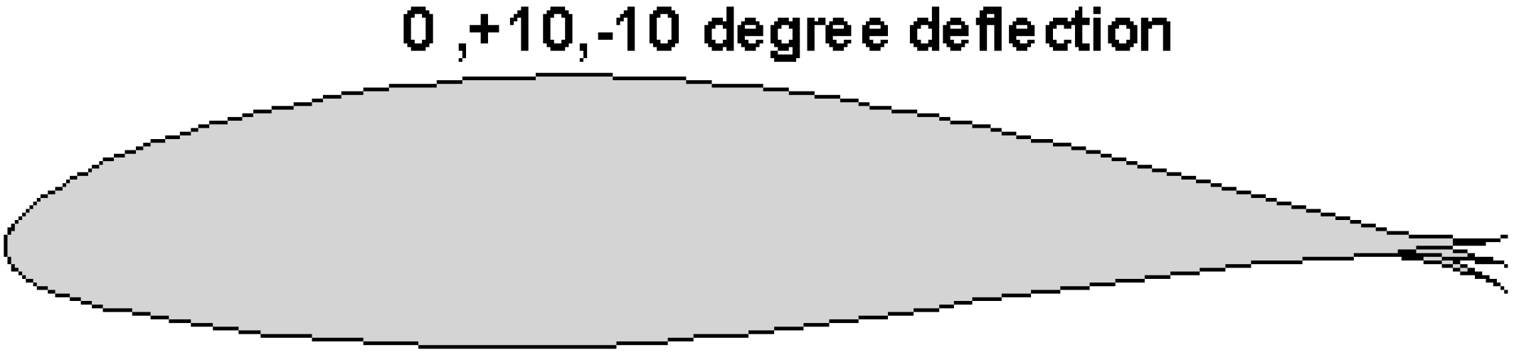
3. Aerodynamics of Deformable Trailing Edge Flap

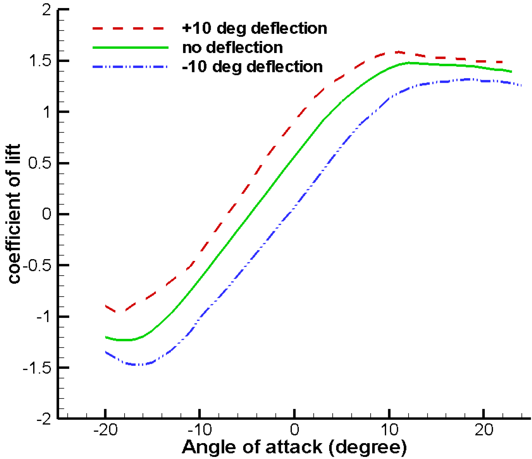
3.1. Aerodynamic Parameters of DTEF

Since this paper is mainly focused on the effectiveness of the smart rotor control with DTEF in operating wind turbine conditions, and not the optimal flap itself, one DTEF was distributed on 70% to 90% of each blade span of the reference turbine, where the airfoil cross section is NACA 64618. The deflection angle of the DTEF with a length of 10% chord, lay within ±10°, shown in Figure 1, for which Troldborg [11] noted optimal performance when he investigated how the deformable flap affected two-dimensional airfoil aerodynamics.
Figure 1. NACA64618 airfoil with a DTEF, 10% chord length, ±10° deflection.
Energies 05 03608 g001
Considering the importance of flap aerodynamics on smart rotor control, the lift, drag and moment coefficients, i.e., Cl, Cd and Cm, of the blade section with DTEF were obtained using RFOIL code. By improving numerical stability, adjusting the closure relations for the turbulent boundary layer formulation and featuring a formulation of radial flow in boundary layer equations [23], RFOIL code better predicts airfoil stall characteristics than XFOIL code and the later has been utilized by some previous investigations [15,16]. To indicate this, Figure 2 shows Cl as a function of angle of attack α for a NACA64618 airfoil without flaps computed by XFOIL or RFOIL codes, in contrast with wind tunnel experimental results measured by Abbott [24,25]. It is evident that the results calculated from both XFOIL and RFOIL are consistent with the results of experiments for the attached flow region, but RFOIL results are much better for the stall region.
Figure 2. Cl vs. α for comparisons of XFOIL, RFOIL and experiment results.
Energies 05 03608 g002
All the data computed by XFOIL code was input into Aerodyn code in terms of tables Cl, Cd and Cm, respectively, one table for each trailing edge flap deflection angle. Specifically, Cl, Cd and Cm, as a function of α ranged from −20° to 23°, were first generated by RFOIL code, with flap deflection angles ranging from −10 degrees to 10 degrees in 1 degree increments. The Reynolds number based on mean chord was 6 × 10⁶. After that, airfoil tables were pre-processed using AirfoilPrep spreadsheets [26], which apply the Viterna method to expand performance to the α range of −180° ~ +180° required by the Aerodyn code. The typical Cl of NACA64618 for airfoils with a deflection angle of ±10° is shown in Figure 3. As is evident, due to the controllable DTEF, the entire lift curve was effectively shifted up or down, consistent with the finding of Johnson et al. [27], where the increased lift corresponds to the downward movement of DTEF in Figure 3.
Figure 3. Cl vs. α of NACA64618 airfoil with 0° and ±10° flap deflection.
Energies 05 03608 g003

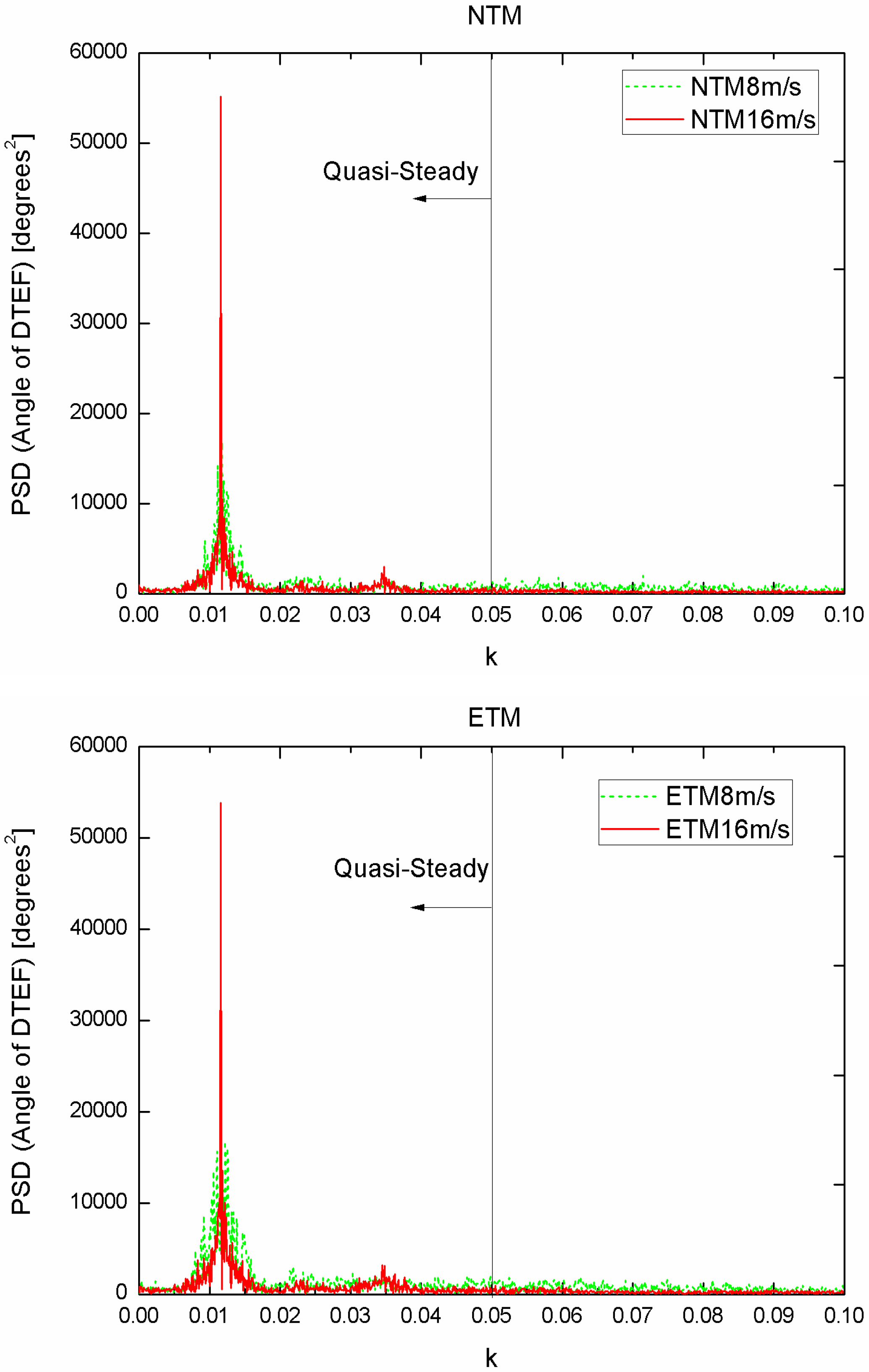
3.2. Unsteadiness Evaluation of DTEF

Generally speaking, the present simulations assume a quasi-steady aerodynamic behavior of airfoil sections. That is, by assuming that Cl, Cd and Cm change with each time step dependent solely on the values of attack angle and the DTEF deployment angle, and not on how quickly these parameters are changing. In reality, the rapid change in the angle of attack does not result in an instantaneous change in Cl, Cd and Cm, but stays over some period of time until they reach a steady state value.
To verify the assumption of quasi-steady aerodynamics is a valid approximation, we used a similar analysis method as Lackner et al. [15] by examining the reduced frequency k, i.e., k = /U, representing the degree of unsteadiness of an airfoil section subject to external disturbance. Here c, U and ω stand for the local chord length of the section, the local relative velocity at the section and the frequency of the disturbance, in units of radians per second, respectively. Figure 4 displays the typical dependence of the power spectral density (PSD) of the flap deflection angle, corresponding to DTEF section, on reduced frequency k for each flap simulation under two load cases (8, 16 m/s for IEC Normal Turbulence Model and Extreme Turbulence Model, as indicated in the Section 5.1). For simplicity, only the first blade at blade station r = 52.75 m (80% blade span) was calculated, where the middle part of DTEF was located with c = 2.518 m and the average U was utilized. As is evident, irrespective of NTM or ETM case, the major peaks in the spectrum occur around k = 0.014 for all simulations, much less than k = 0.05, beyond which the aerodynamics of airfoil section can be considered to be unsteady [15].
Figure 4. DTEF deflection spectrum.
Energies 05 03608 g004
Furthermore, the percentages of energy in the quasi-steady and unsteady region were quantified by integrating the PSD of the DTEF deflection angle in Figure 4 between k = 0 and k = 0.05, and then beyond k = 0.05, listed in Table 2. Clearly, majority of energy, approximately 95% or more, are in the steady/quasi-steady region for all NTM and ETM cases.
Table 2. Proportion of DTEF Spectrum in the Steady Region.
Mean wind speed U ¯ [m/s]NTM, steady proportion (%)ETM, steady proportion (%)
496.4597.09
897.4097.85
1299.0499.17
1699.1899.27
2099.2699.35
2499.3599.41
All these results suggest that even though the aerodynamic of DTEF sections, which may greatly influence the smart rotor simulations, are not entirely quasi-steady, it is indeed a safe assumption to do so. The unsteady aerodynamic behaviors of other sections, e.g., inboard section, will vary little across all simulations and not exert much effect on the comparisons in control performance due to non-existence of DTEF. On the other hand, the unsteady aerodynamics of flap action can be much more correctly computed using unsteady models, e.g., newly developed models by Gaunaa and Andersen et al. [28,29], who provide very promising dynamic stall and dynamic inflow models to predict unsteady aerodynamic forces and moments on an airfoil section undergoing arbitrary motion like the present case with deformable trailing edge flap. Integration of these models into Aerodyn code will undoubtedly further improve aerodynamic environment of smart rotor system and will be conducted in our future work.

4. Smart Rotor Control System Design

4.1. Basic Control Design

The original basic control (BC) system built by NREL was used for the reference 5 MW turbine model, which includes two kinds of controllers: generator-torque controller and collective pitch controller. For the former, generator torque is computed as a tabulated function of the filtered generator speed, incorporating five control regions: 1, 1½, 2, 2½, and 3. Region 1 is a control region at a wind speed lower than cut-in speed where the generator torque is zero, with no power being extracted; Region 2 is a control region for optimizing power capture where generator torque is proportional to the square of the filtered generator speed to maintain a constant tip-speed ratio; in Region 3, the generator power is held constant so that generator torque is inversely proportional to the filtered generator speed. Region 1½ and Region 2½ are respectively the linear transition areas between Regions 1 and 2, and Regions 2 and 3.
For the latter, a full-span collective blade pitch controller is developed using gain scheduled proportional-integral control based on speed error between the filtered generator speed and the rated one in Region 3 [22].

4.2. DTEF Control Design

The main purpose of the basic control described above is to control the power of turbine. To effectively control the DTEF in order to reduce aerodynamic load on turbines, the development of a more advanced method is required. In doing so, the flap controller was independently designed (see the structure in Figure 5). The detailed procedure for design is as follows:
First, the root flapwise bending moment of the three blades, My1, My2 and My3, were chosen as input for the feedback smart rotor controller.
Second, multi-blade transformation [30] or Coleman transformation [15] was introduced, which depends on the fact that the blades are in a rotating coordinate system, leading to the existence of periodic coefficients in the equations of motion related to My1, My2, My3 and the DTEF; and they need to be removed for simplification. Though not entirely true, after transformation, variables in the fixed coordinate system can be assumed to be time-invariant, so that LTI control techniques can be used [30,31].
Specifically, considering the three blades of the turbine were spaced equally within the rotor plane, the azimuth location of the bth blade was calculated as:
ψ b = ψ 1 + 2 π 3 ( b 1 )   b = 2 , 3
where ψ1 is the azimuth of the first blade and ψ1 = 0 stands for the first blade to stand vertically up.
To build a relationship among yaw moment, tilt moment in the fixed coordinate system on nacelle and blade root moment in the rotating coordinate system, the forward multi-blade transformation was:
{ M y 0 ( t ) = 1 3 b = 1 3 M yb ( t ) M ys ( t ) = 2 3 b = 1 3 M yb ( t ) sin ψ b ( t ) M yc ( t ) = 2 3 b = 1 3 M yb ( t ) cos ψ ( t ) b
where ψ is the azimuth angle, Mys(t) and Myc(t) are the static yaw and tilt moments in the fixed nacelle frame. The My0(t) is the average blade root flapwise bending moment, which is not particularly useful in the present study. Through the transformation, Mys(t) and Myc(t) in the fixed coordinate system were nearly independent, and the feedback control system could be decoupled into two independent single input and single output subsystems [31,32]. Though the assumption of independence between Mys(t) and Myc(t) is not entirely correct, as in Bossayni [33], their relationship was ignored for simplicity in this study.
Then, the classical control technique proportional-integral-derivative (PID) was introduced. The PID controller was based on the error input between the reference rin(k) and the actual feedback input yin(k):
E r r o r ( k ) = r i n ( k ) y i n ( k )
The PID controller law [34] is:
u ( t ) = k P ( e r r o r ( t ) + 1 T I 0 t e r r o r ( t ) d t + T D d e r r o r ( t ) d t )
where Kp, TI and TD represent the proportional coefficient, the integration time constant, and the derivative time constant, respectively.
Furthermore, since the goal of the flap controller in this paper is to minimize the asymmetrical loads Mys(t) and Myc(t), the corresponding referenced variations were always zero. The governing equations for Mys(t) and Myc(t) are:
θ s ( t ) = k P ( ( 0 M ys ( t ) ) + 1 T I 0 t ( 0 M ys ( t ) ) d t + T D d ( 0 M ys ( t ) ) d t )
θ c ( t ) = k P ( ( 0 M yc ( t ) ) + 1 T I 0 t ( 0 M yc ( t ) ) d t + T D d ( 0 M y c ( t ) ) d t )
where θs(t) and θc(t) are the yaw-wise and tilt-wise TEF deployment angle, respectively, defining how the individual DTEF angle vary from the collective one. As mentioned before, this research does not aim to obtain an approach for optimal control, but to achieve effective load reduction. Therefore, the gains of PID controller were set to gain a considerable reduction in the fluctuation of My1, My2 and My3 during all investigated wind conditions and to maintain steady power output in Region 2 and Region 3. After numerous tests, TI and TD were set as 3 and 1/60, respectively, while the relationship between the numerical values of the mean wind speed ( U ¯ ) and KP in both Formula (5) and Formula (6) were acquired with:
K P = 0.00225 U ¯ + 0.072
Note the main purpose of the present paper at present stage is to develop an aero-servo-elastic platform for conducting smart rotor control work in an easier way and thus the classical PID control scheme was chosen. Note that besides the PID scheme, some more advanced ones, e.g., H feedback and feedforward control scheme [12,13], have already been developed and their control effectiveness has been proved. Based on these researches, the development of optimum control scheme will be one promising direction of our future work.
Finally, the following inverse multi-blade transformation was used to transform variables from the fixed frame of reference into the rotating frame of reference:
θ b ( t ) = θ 0 ( t ) + θ s ( t ) sin ψ b ( t ) + θ c ( t ) cos ψ b ( t ) ;   b = 1 , 2 , 3
where θb(t) is the DTEF deployment angle of the bth blade in rotating coordinates and θ0(t), the collective DTEF deployment angle in the fixed frame, which can be neglected by setting the value to zero at all times, or be used to augment rotor speed control by acting simultaneously with the basic collective pitch action [15]. The two situations will be investigated in the next section.
In the case of θ0(t), a simple P controller was used, based on speed error between the generator speed and the rated generator speed. Here θ0(t) is superimposed on the individual θs(t) and θc(t), used for load control. In this study, the action of θ0(t) for rotor speed control was only applied when the collective pitch angle was greater than 5° in Region 3. Likewise, the proportional gain for controlling the collective flap angle, KPc, was adjusted so that fluctuations of pitch action and power output were reduced while gaining even greater load reduction. Finally, the relationship between the numerical values of U ¯ and KPc were calculated as:
K P c = 0.00125 U ¯ + 0.04
The deployment angle range of the individual DTEF and collective DTEF was limited to ±10° and ±5°, respectively, and the actuator maximum rate was limited to ±40 °/s.
The detailed feedback control scheme integrating DTEF into FAST/Aerodyn and Matlab/Simulink codes for the NREL UpWind/5 MW reference turbine is shown in Figure 5.
Figure 5. Feedback control scheme of DTEF implemented in FAST/Aerodyn and Matlab/Simulink codes.
Energies 05 03608 g005

5. Simulation Results and Analysis

5.1. External Conditions for Simulations

In order to investigate the effect of the smart rotor control system on load reduction, two kinds of external conditions were taken into consideration: Normal Turbulence Model (NTM) and Extreme Turbulence Model (ETM), which were computed according to International Electrotechnical Commission (IEC) standard “IEC 61400-1 Ed.3: Wind turbines-Part 1: Design requirements” [35]. In accordance with IEC standards, wind class IIB with reference speed Vref and turbulence intensity Iref of 42.5 m/s and 0.14 at hub height were chosen for calculation. Performance under mean wind speed values of 4, 8, 12, 16, 20 and 24 m/s, which nearly cover all operating wind speeds, were considered (see Table 3) along with the corresponding longitudinal turbulence intensity. Wind data was generated with Turbsim (a stochastic, full-field, turbulent-wind simulator) [36], with 3D turbulent wind formed using a von Karman spectrum. A wind shear power law exponent of 0.2 was used in all cases.
Table 3. Longitudinal turbulence intensity for all simulation cases.
Mean wind speed U ¯ [m/s]4812162024
Turbulence intensity for NTM30.120.317.015.414.413.8
Turbulence intensity for ETM62.735.025.821.218.416.5

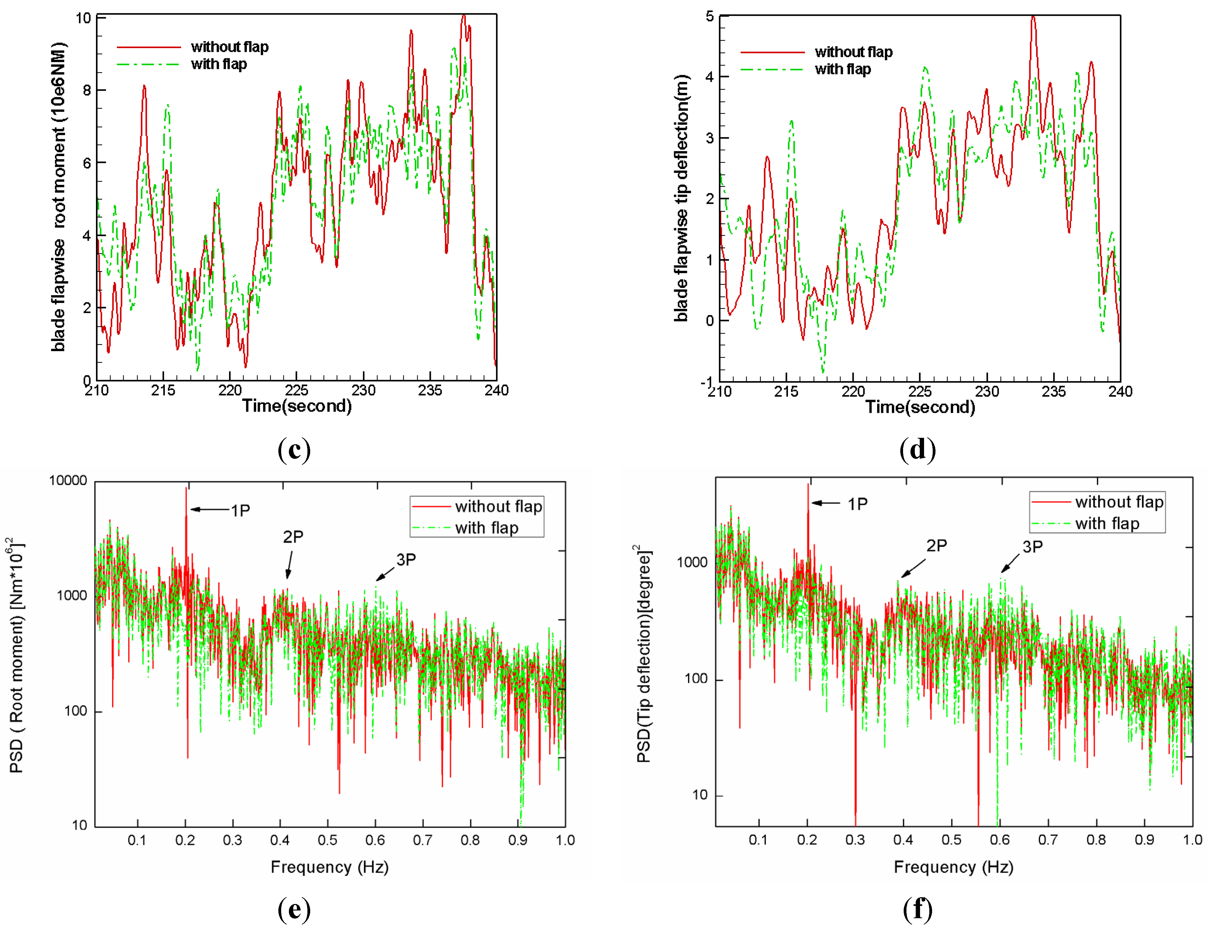
5.2. Effects of Smart Rotor Control on Blades

5.2.1. Normal Turbulence Results

Figure 6 shows typical 30 s time-series and PSD results at U ¯ of 16 m/s under NTM. Here the first blade is chosen as an example.
Figure 6. Time and frequency domain results for NTM at 16m/s: (a) longitudinal wind speed; (b) deployment angles of three TEFs; (c) blade flapwise root moment My1; (d) blade flapwise tip deflection BTd1; (e) PSD of My1; (f) PSD of BTd1.
Energies 05 03608 g006
Figure 6(a) shows a typical time series of longitudinal wind speed at the hub and the tip of blade 1. It is evident that the existence of wind shear and fluctuating turbulence greatly differentiates wind speed within the rotor plane. From Figure 6(b), we can see that all three DTEFs take effect, but about 120° phase difference exists among them. Clearly, after the introduction of DTEF, fluctuation in the flapwise root moment (My1) and blade flapwise tip deflection (BTd1) were suppressed to some degree [Figure 6(c,d)]; the spectral peaks, corresponding to the first flapwise mode frequency of the blade (1P), were significantly reduced and the peaks at 2P and 3P frequencies were a little increased [Figure 6(e,f)].
To further quantify the performance, the std of My and BTd and 1 Hz damage equivalent load (DEL) of My1, i.e., DEL(My1), during all NTM cases over 630 s simulation were compared (Table 4). DEL(My1) was calculated by converting My1 into a stress value, and then using a rain flow counting method to determine the number of cycles at various amplitudes. A value of 10 was used for the inverse slope of the S-N curve to calculate the values of DEL(My1). Here we consider three situations: (a) basic control, i.e., BC case; (b) basic control with flap control and a disabled θ0(t), i.e., BC + FC case; (c) basic control with flap control and θ0(t) in use, i.e., BC + FC + CFC case. From Table 4, it is clear that, compared with BC case, effective load reduction under all NTM conditions can be achieved using DTEF-based smart rotor control system. The greatest reduction in My1 and BTd1 were up to 20% in std of My1 and 22.8% in DEL(My1) for the former case and 15.7% in std of BTd1 for the latter. These results match or are even an emphasis over the results of previous investigations [15,17], which employed similar concepts of control but different technical routes for building the external flap controllers. For the former, the DTEF controller was built based on a commercial aeroelastic simulation package GH Bladed, while for the later, the controller of the conventional flap was developed using FAST/Aerodyn/Simulink code with the feedback signal from tip deflection or tip deflection rate, not root flapwise bending moment, as deployed in the present paper. All the results completely prove the effectiveness of the presently developed smart rotor control system.
Table 4. Std of My1 and BTd1 for NTM case.
My1
BCBC + FCBC + FC + CFC
U ¯ [m/s]Std [106 NM]Std [106 NM]Reduction std [%]Reduction DEL [%]Std [106 NM]Reduction std [%]Reduction DEL [%]
40.540.523.72.10.523.72.1
81.251.176.410.01.176.410.0
122.081.899.119.01.8112.922.8
162.151.8115.814.61.7319.59.4
202.261.8518.119.61.8020.419.1
242.582.2014.77.82.1815.513.6
BTd1
BCBC + FCBC + FC + CFC
U ¯ [m/s]Std [106 NM]Std [106 NM]Reduction [%]Std [106 NM]Reduction [%]
40.320.36.30.36.3
80.730.6313.70.6313.7
121.291.1510.91.1113.9
161.271.1013.41.0715.7
201.271.1013.41.0815.0
241.441.319.01.309.7

5.2.2. Extreme Turbulence Results

As with NTM, research work was also conducted using ETM. Figure 7 shows typical 30s time-series and PSD results on the 1st blade at U ¯ of 16 m/s. As in the case of NTM, smart rotor control affects My1 and BTd1 [illustrated in Figure 7(b–f)]. My1 was effectively decreased by up to 15.0% in std of My1 and 22.2% in DEL(My1) , while the std of BTd1 was reduced up to 11.9% (indicated in Table 5). Correspondingly, the peaks of My1 and BTd1 at 1st flapwise mode frequency (1P) were effectively reduced while the peaks were seen again to be slightly enhanced at 2P and 3P [Figure 7(e,f)]. Note the performance is a little less prominent than with NTM. This is natural in that for the same U ¯ , turbulence intensity under ETM is much greater than under NTM [Table 3 and Figure 6(a) and Figure 7(a)] and control will be difficult to apply, leading to performance inferiority in the former over the later.
It is also notable that the deployment of collective flap angles additionally contributes to load reduction (Table 4 and Table 5). This is partially related to fluctuation suppression in full-span blade pitch and generator power (Table 7).
Figure 7. Time and frequency domain results for ETM at 16 m/s: (a) longitudinal wind speed; (b) deployment angles of three TEFs; (c) blade flapwise root moment My1; (d) blade flapwise tip deflection BTd1; (e) PSD of My1; (f) PSD of BTd1.
Energies 05 03608 g007aEnergies 05 03608 g007b
Table 5. Std of My1 and BTd1 for ETM case.
My1
BCBC + FCBC + FC + CFC
U ¯ [m/s]Std [106 NM]Std [106 NM]Reduction std [%]Reduction DEL [%]Std [106 NM]Reduction std [%]Reduction DEL [%]
41.040.958.722.20.958.722.2
82.041.935.413.11.935.413.1
122.522.318.318.62.2311.519.6
162.672.3810.913.52.2814.69.6
202.602.2613.117.22.2115.019.1
242.822.4812.18.52.4612.812.0
BTd1
BCBC + FCBC + FC + CFC
U ¯ [m/s]Std [106 NM]Std [106 NM]Reduction [%]Std [106 NM]Reduction [%]
40.580.538.60.538.6
81.141.057.91.057.9
121.531.399.21.3611.1
161.591.458.81.4011.9
201.471.348.81.3210.2
241.591.477.51.477.5

5.3. Effects of Smart Rotor Control on Power and Tower Load

In addition to the effect on blades, the functions of the smart rotor control on mean power and tower load were also processed. Table 6 lists the reduction percentage of mean generator power, fore-aft tower root moment and fore-aft tower top deflection using DTEF control when θ0(t) was disabled, in comparison with basic control. Table 6 shows variation of mean generator power is very slight, suggesting smart rotor control systems positively affect load reduction while maintain the extracting power invariant. This indicates that the conduction of the basic control and flap control systems little interfere with each other.
On the other hand, the fore-aft tower root moment and fore-aft tower top deflection were effectively reduced by up to 5.7% and 9.8%, respectively, at U ¯ of 20 m/s. Clearly, the load on the blades directly affect those on the tower, the drive train and other components of turbine and the decreased Myb is mainly responsible for the reduced load on the tower. It should be noted, the fore-aft tower root moment and fore-aft tower top deflection slightly increase at U ¯ of 4 m/s, possibly due to the saturation or ineffective control related to the largest turbulence intensity (62.7%).
Table 6. Reduction percentage of mean power and load on tower using DTEF control (%).
NTM
U ¯ [m/s]4812162024
Mean generator power1.1−5.30.019000.016
FA tower root moment−1.61.31.73.45.75.0
FA tower top deflection−1.71.93.06.29.78.3
ETM
U ¯ [m/s]4812162024
Mean generator power3.71.00.0170.0300.018
FA tower root moment−1.01.01.33.25.74.8
FA tower top deflection01.82.85.89.87.8

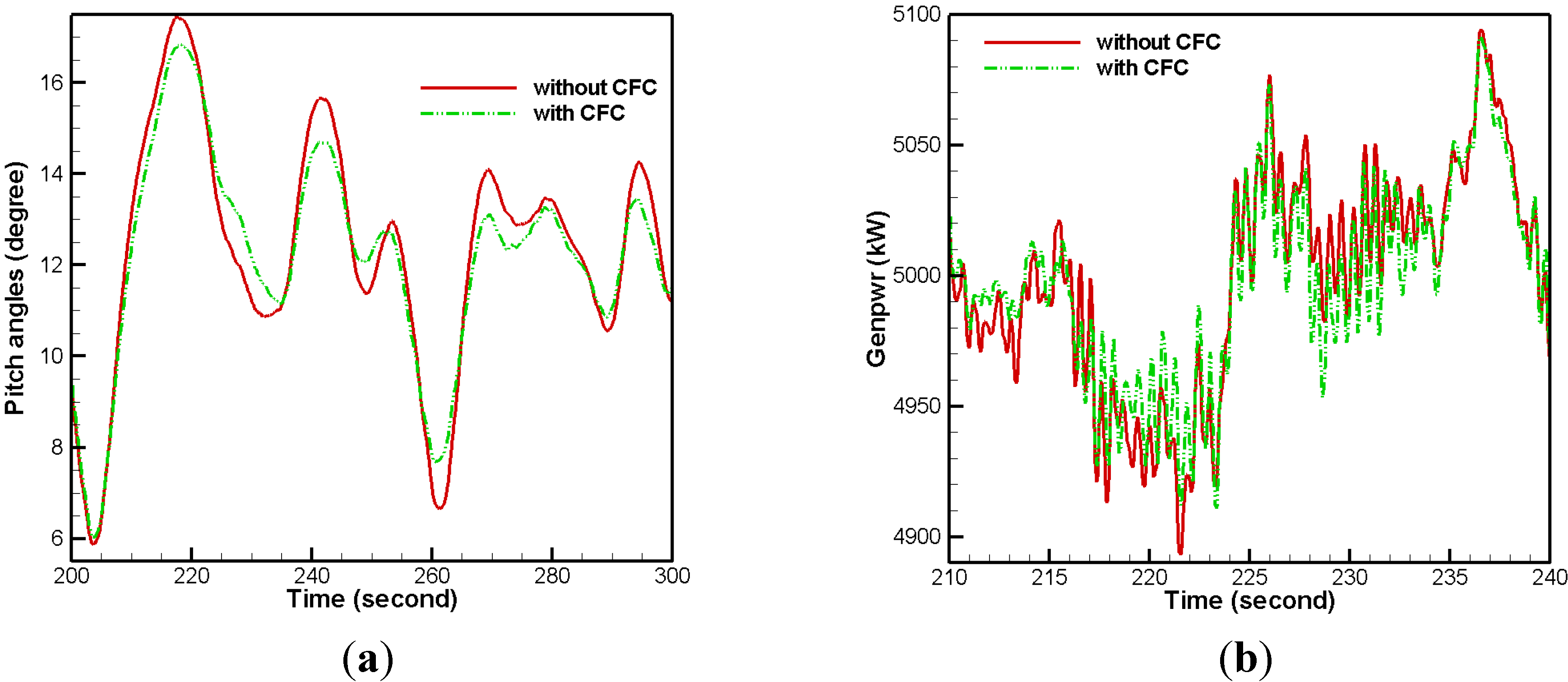
5.4. Effects of Smart Rotor Control on Power and Pitch System Using the Collective DTEF Deployment Angle

Table 7 compares the smart rotor control effect on std reduction in pitch angle and generator power with and without θ0(t), as opposed to the effect of basic control. It shows an increase in the std of pitch angle and generator power for the majority of cases in the absence of θ0(t), i.e., FC. However, with θ0(t), i.e., FC + CFC, std of pitch angle and generator power are reduced for all load conditions with maximum reductions in the former up to 7.8% and up to 3.6% in the later. The typical time domain results at U ¯ of 16 m/s are illustrated in Figure 8. It clearly shows that deviation from the rated generator power (5 MW) is smaller and amplitudes of pitch angles are lessened for CFC. These results mean the deployment of θ0(t) may contribute to a smoother power output and less wear of the pitch control system.
Table 7. Reduction of Std of Pitch Angle and Generator power (%).
NTM
U ¯ [m/s]12162024
Pitch Angle
Std
FC5.80.5−1.0−0.4
FC + CFC6.17.83.72.5
Generator power
std
FC0.10.1−2.7−2.9
FC + CFC3.23.03.20.4
ETM
U ¯ [m/s]12162024
Pitch Angle
Std
FC1.2−0.03−1.2−0.7
FC + CFC5.65.83.12.1
Generator power
std
FC−0.1−0.8−2.5−3.0
FC + CFC0.82.93.60.8
Figure 8. Time domain results with and without CFC at NTM 16 m/s; (a) pitch angles; (b) generator power.
Energies 05 03608 g008

6. Conclusions

This paper has mainly focused on the design of smart rotor control and its effectiveness on large scale offshore wind turbines with an aim to reduce aerodynamic load. The major conclusions can be listed as follows:
(1)
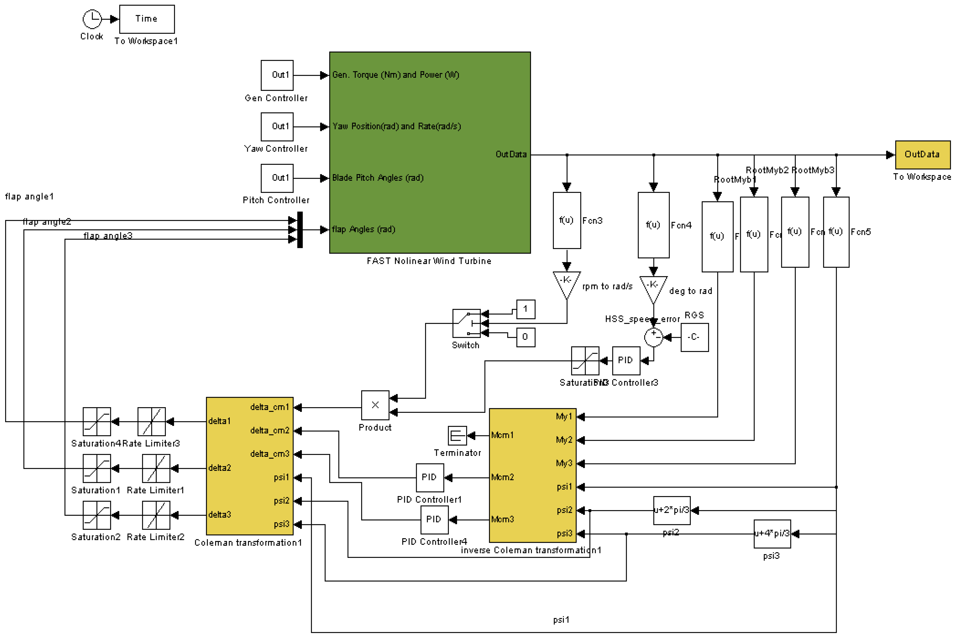
A new aero-servo-elastic platform, based on FAST/Aerodyn and Matlab/Simulink codes, was successfully built to implement smart rotor control using DTEF.
(2)
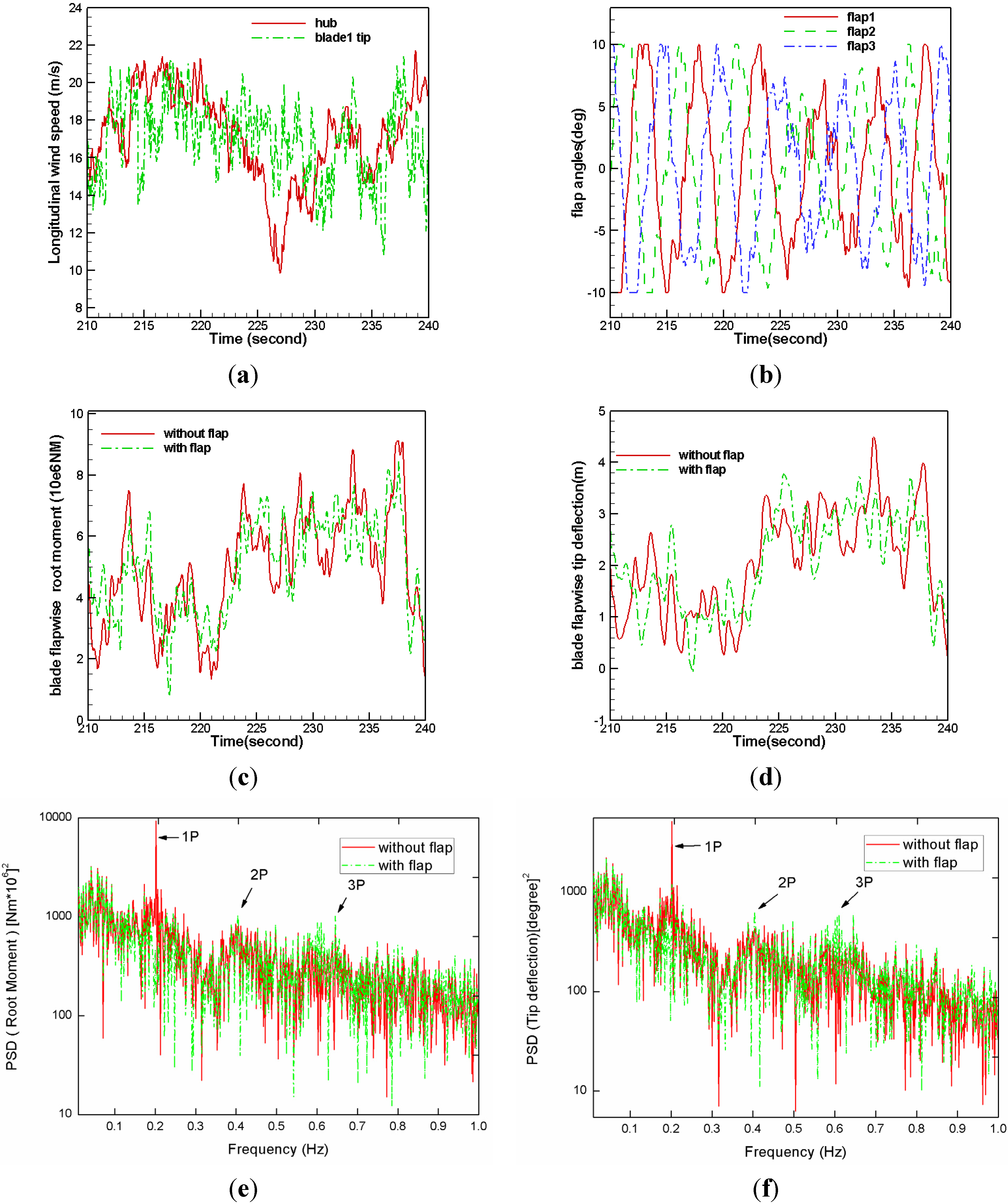
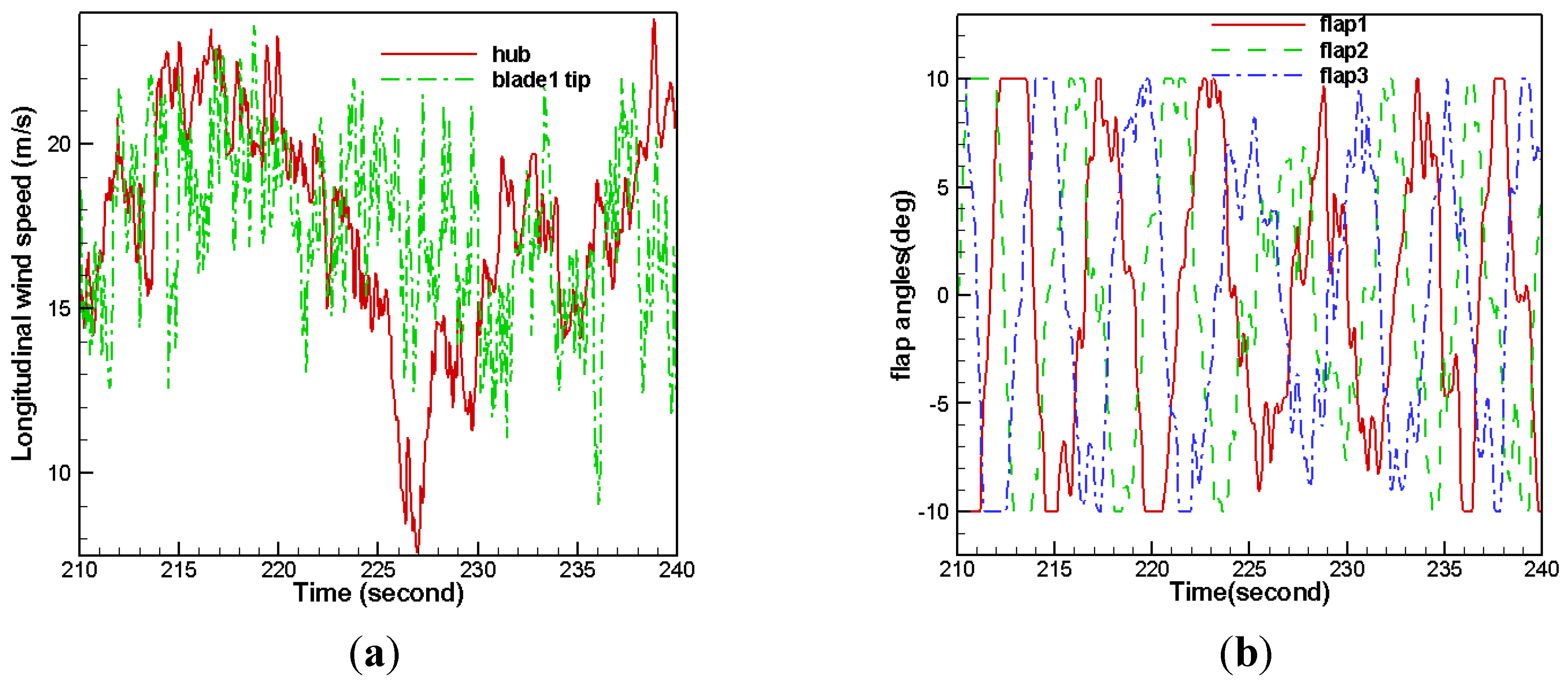
Using the newly developed smart rotor control, fluctuating aerodynamic load on blades was effectively reduced under NTM and ETM turbulence conditions. Maximum reduction in flapwise root moment and tip deflection was up to 20.4% and 15.7%, respectively, for NTM, and up to 15.0% and 11.9%, respectively, for ETM.
(3)
Load reduction on blades with the smart rotor control system also had positive effect on tower load and power generation.
(4)
Adoption of a collective flap angle might assist in reducing power fluctuation and reducing wear on the pitch control system.
Using numerical simulation, this study has demonstrated a new aero-servo-elastic platform, based on which smart rotor control using DTEF can be designed to effectively reduce turbine load. Nevertheless, there remains work to be done in terms of the development of advanced aeroelasticity and control models to further optimize control performance.

Acknowledgments

This work was supported by the National Natural Science Foundation of China (Grant No. 51222606), “Hundred Talent Program” of Chinese Academy of Sciences and Sino-Denmark Collaboration Project (Grant No. 2010DFA62830).

References

  1. Musial, M.; Butterfield, S. Energy from offshore wind. In Proceedings of Offshore Technology Conference, Houston, TX, USA, 1–4 May 2006.
  2. Fichaux, N.; Beurskens, J.; Jensen, P.H.; Wilkes, P. Design Limits and Solutions for Very Large Wind Turbines—A 20 MW Turbine Is Feasible; UpWind Report; European Wind Energy Association: Brussels, Belgium, 2011. [Google Scholar]
  3. Veers, P.S.; Ashwill, T.D.; Sutherland, H.J.; Laird, D.L.; Lobitz, D. Trends in the design, manufacture and evaluation of wind turbine blades. Wind Energy 2003, 6, 245–259. [Google Scholar] [CrossRef]
  4. Barlas, T.K.; van Kuik, G.A.M. State of the art and prospectives of smart rotor control for wind turbines. J. Phys. Conf. Ser. 2007, 75, 1–20. [Google Scholar] [CrossRef]
  5. Collis, S.S.; Joslin, R.D.; Seifert, A.; Theofilis, V. Issues in active flow control: Theory, control, simulation and experiment. Prog. Aerosp. Sci. 2004, 40, 237–289. [Google Scholar] [CrossRef]
  6. Chopra, I. Review of state of art of smart structures and integrated systems. Am. Inst. Aeronaut. Astronaut. J. 2002, 40, 2145–2187. [Google Scholar] [CrossRef]
  7. Migliore, P.G.; Quandt, G.A.; Miller, L.S. Wind Turbine Trailing Edge Aerodynamic Brake; NREL/TP—441-7805; Technical Report; NREL: Washington, DC, USA, 1995. [Google Scholar]
  8. Stuart, J.G.; Wright, A.D.; Butterfield, C.P. Considerations for an Integrated Wind Turbine Controls Capability at the National Wind Technology Center: An Aileron Control Case Study for Power Regulation and Load Mitigation. NREL/TP—440-21335. In Proceedings of American Wind Energy Association (AWEA) Conference, Denver, CO, USA, 23–27 June 1996.
  9. Barlas, T.K.; van Kuik, G.A.M. Review of state of the art in smart rotor control research for wind turbines. Prog. Aerosp. Sci. 2010, 46, 1–27. [Google Scholar] [CrossRef]
  10. Basualdo, S. Load alleviation on wind turbine blades using variable airfoil geometry. Wind Eng. 2005, 29, 169–182. [Google Scholar] [CrossRef]
  11. Troldborg, N. Computational study of the Risø-B1-18 airfoil with a hinged flap providing variable trailing edge geometry. Wind Eng. 2005, 29, 89–113. [Google Scholar] [CrossRef]
  12. Van Wingerden, J.W.; Hulskamp, A.; Barlas, T.; Houzager, I.; Bersee, H.; van Kuik, G.; Verhaegen, M. Two-degree-freedom active vibration control of a prototyped “smart” rotor. IEEE Trans. Control Syst. Technol. 2011, 19, 284–296. [Google Scholar] [CrossRef]
  13. Hulskamp, A.W.; van Wingerden, J.W.; Barlas, T.; Champliaud, H.; van Kuik, G.A.M.; Bersee, H.E.N.; Verhaegen, M. Design of a scaled wind turbine with a smart rotor for dynamic load control experiments. Wind Energy 2011, 14, 339–354. [Google Scholar] [CrossRef]
  14. Baek, P. Unsteady Flow Modeling and Experimental Verification of Active Flow Control Concepts for Wind Turbine Blades. Ph.D. Thesis, Technical University of Denmark, Roskilde, Denmark, 2011. [Google Scholar]
  15. Lackner, M.A.; van Kuik, G. A comparison of smart rotor control approaches using trailing edge flaps and individual pitch control. Wind Energy 2010, 13, 117–134. [Google Scholar] [CrossRef]
  16. Lackner, M.A.; van Kuik, G. The performance of wind turbine smart rotor control approaches during extreme loads. J. Solar Energy Eng. 2010, 132, 011008:1–011008:8. [Google Scholar] [CrossRef]
  17. Wilson, D.G.; Berg, D.E.; Barone, M.F.; Berg, J.C.; Resor, B.R.; Lobitz, D.W. Active aerodynamic blade control design for load reduction on large wind turbines. In Proceedings of European Wind Energy Conference & Exhibition, Marseille, France, 16–19 March 2009.
  18. Wilson, D.G.; Resor, B.R.; Berg, D.E.; Barlas, T.K.; van Kuik, G.A.M. Active aerodynamic blade distributed flap control design procedure for load reduction on the UPWind 5 MW wind turbine. In Proceedings of 48th AIAA Aerospace Sciences Meeting Including the New Horizons Forum and Aerospace Exposition, Orlando, FL, USA, 4–7 January 2010.
  19. Andersen, P.B. Advanced Load Alleviation for Wind Turbines Using Adaptive Trailing Edge Flaps: Sensoring and Control. Ph.D. Thesis, Technical University of Denmark, Roskilde, Denmark, 2010. [Google Scholar]
  20. Jonkman, J.; Buhl, M.L. FAST User’s Guide; NREL/EL-500-29798; Technical Report; NREL: Golden, CO, USA, 2005. [Google Scholar]
  21. Laino, D.J.; Hansen, A.C. AeroDyn User’s Guide; Technical Report; NREL: Salt Lake City, UT, USA, 2002. [Google Scholar]
  22. Jonkman, J.; Butterfield, S.; Musial, W.; Scott, G. Definition of a 5-MW Reference Wind Turbine for Offshore System Development; NREL/TP-500-38060; Technical Report; NREL: Golden, CO, USA, 2009. [Google Scholar]
  23. Van Rooij, R.P.J.O.M. Modification of the Boundary Layer Calculation in RFOIL for Improved Airfoil Stall Prediction; Report IW-96087R; Technical Report; Delft University of Technology: Delft, The Netherland, 1996. [Google Scholar]
  24. Abbott, I.H.; von Doenhoff, A.E. Theory of Wind Sections-Including a Summary of Airfoil Data; Dover Publications Inc.: New York, NY, USA, 1959; p. 587. [Google Scholar]
  25. Kooijman, H.J.T.; Lindenburg, C.; Winkelaar, D.; van der Hooft, E.L. DOWEC 6 MW Pre-Design: Aeroelastic Modelling of the DOWEC 6 MW Pre-Design in PHATAS; DOWEC-F1W2-HJK-01-046/9; Technical Report; Energy Center of the Netherlands: Petten, The Netherlands, 2003. [Google Scholar]
  26. National Renewable Energy Lab., NWTC Design Codes (AirfoilPrep); NREL: Golden, CO, USA, 2004. Available online: http://wind.nrel.gov/designcodes/preprocessors/airfoilprep/ (accessed on 11 November 2010).
  27. Johnson, S.J.; van Dam, C.P.; Berg, D.E. Active Load Control Techniques for Wind Turbines; SAND 2008-4809; Technical Report for Sandia National Laboratories: Albuquerque, NM, USA, 2008. [Google Scholar]
  28. Andersen, P.B.; Gaunaa, M.; Bak, C.; Hansen, M.H. A dynamic stall model for airfoils with deformable trailing edges. Wind Energy 2009, 12, 734–751. [Google Scholar] [CrossRef]
  29. Gaunaa, M. Unsteady two-dimensional potential-flow model for thin variable geometry airfoils. Wind Energy 2010, 13, 167–192. [Google Scholar] [CrossRef]
  30. Bir, G. Multiblade coordinate transformation and its application to wind turbine analysis. NREL/CP-500-42553. In Proceedings of ASME Wind Energy Symposium, Reno, NV, USA, 7–10 January 2008.
  31. Van Engelen, T.G.; van def Hooft, E.L. Individual Pitch Control Inventory; ECN Report No. ECN-C-03-138; ECN Windenergie: Petten, The Netherlands, 2005. [Google Scholar]
  32. Van Engelen, T.G. Design model and load reduction assessment for multi-rotational mode individual pitch control (Higher Harmonics Control). In Proceedings of European Wind Energy Conference & Exhibition, Athens, Greece, 27 February–2 March 2006.
  33. Bossayni, E.A. Individual blade pitch control for load reduction. Wind Energy 2003, 6, 119–128. [Google Scholar] [CrossRef]
  34. Johnson, M.A.; Moradi, M.H. PID Control: New Identification and Design Methods; Lan Kingstong Publishing Services: Nottingham, UK, 2005. [Google Scholar]
  35. Wind Turbines—Part 1: Design Requirements; IEC 61400-1 Ed.3; International Electrotechnical Commission: Geneva, Switzerland, 2005.
  36. Jonkman, B.J. Turbsim User’s Guide; Version 1.50; NREL/TP-500-46198; Technical Report for NREL: Golden, CO, USA, 2009. [Google Scholar]

