Experimental and Numerical Analysis of Thermal and Hygrometric Characteristics of Building Structures Employing Recycled Plastic Aggregates and Geopolymer Concrete


Abstract
:1. Introduction

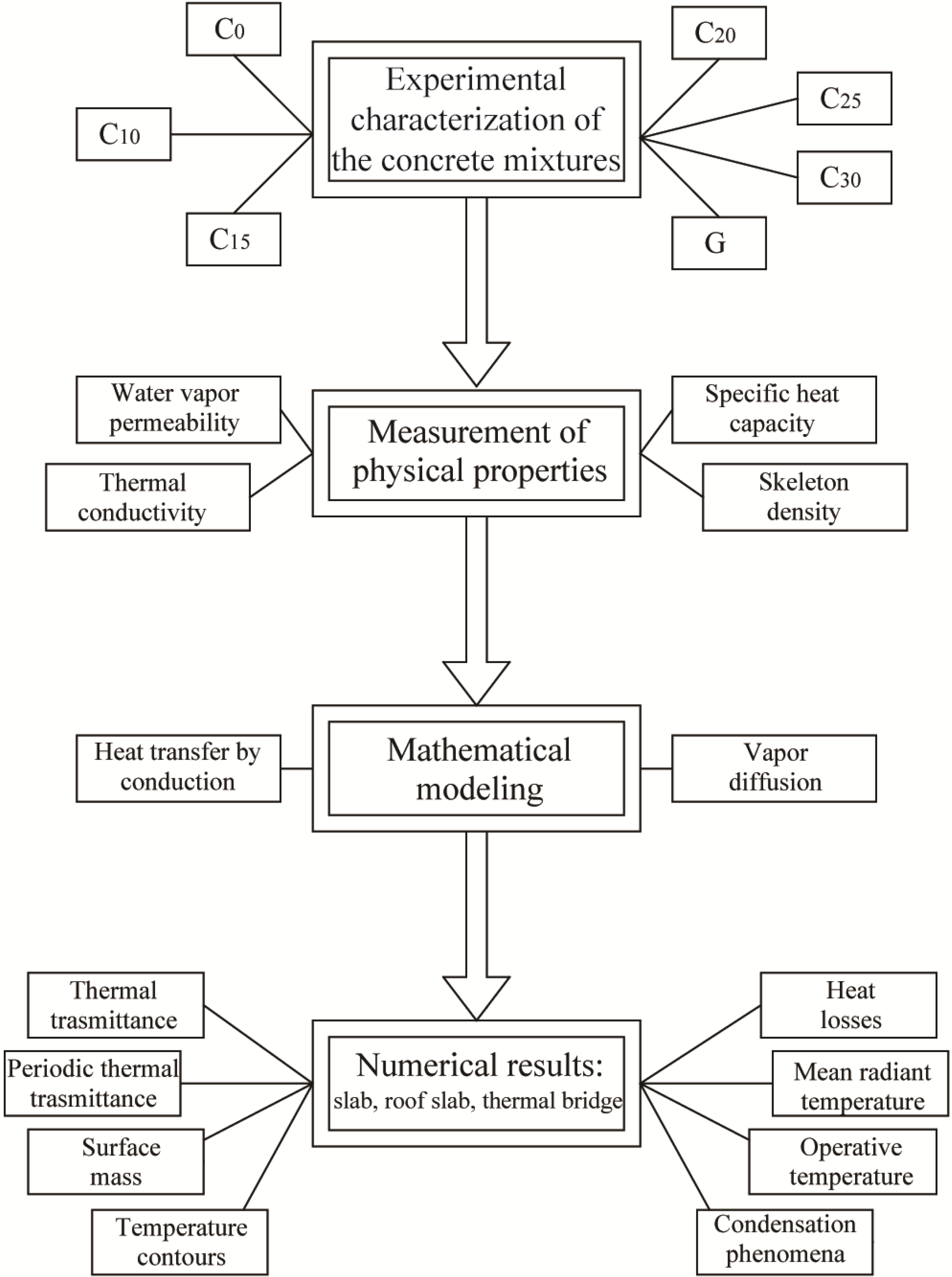
2. Materials Employed in the Experiments

| Oxides | CEM | Fly ash | Marble sludge |
|---|---|---|---|
| CaO | 60.84 | 4.32 | 53.76 |
| SiO2 | 20.66 | 53.75 | 2.13 |
| Al2O3 | 4.89 | 28.12 | 0.12 |
| Fe2O3 | 3.24 | 6.99 | 0.69 |
| MgO | 1.94 | 1.59 | 0.15 |
| SO3 | 2.95 | - | - |
| Na2O | 0.12 | 0.87 | - |
| K2O | 0.84 | 1.89 | - |
| Cl− | 0.94 | - | - |
| LoI * | 5.76 | 6.01 | 42.74 |
| Mixture | G | C0 | C10 | C15 | C20 | C25 | C30 |
|---|---|---|---|---|---|---|---|
| Cement (kg/m3) | - | 300 | 300 | 300 | 300 | 300 | 300 |
| Natural aggregate (kg/m3) | 854 | 1648 | 1351 | 1293 | 1227 | 1203 | 1101 |
| Plastic aggregate (kg/m3) | - | 0 | 70 | 105 | 140 | 175 | 210 |
| Fly ash (kg/m3) | 208 | 90 | 90 | 90 | 90 | 90 | 90 |
| Marble sludge (kg/m3) | - | 146 | 152 | 163 | 171 | 176 | 183 |
| Activating solution (kg/m3) | 138 | - | - | - | - | - | - |
| Acrylic admixture (L/m3) | - | 6.86 | 7.26 | 8.05 | 8.91 | 8.75 | 9.95 |
| Water/cement | N.A. | 0.5 | 0.5 | 0.5 | 0.5 | 0.5 | 0.5 |
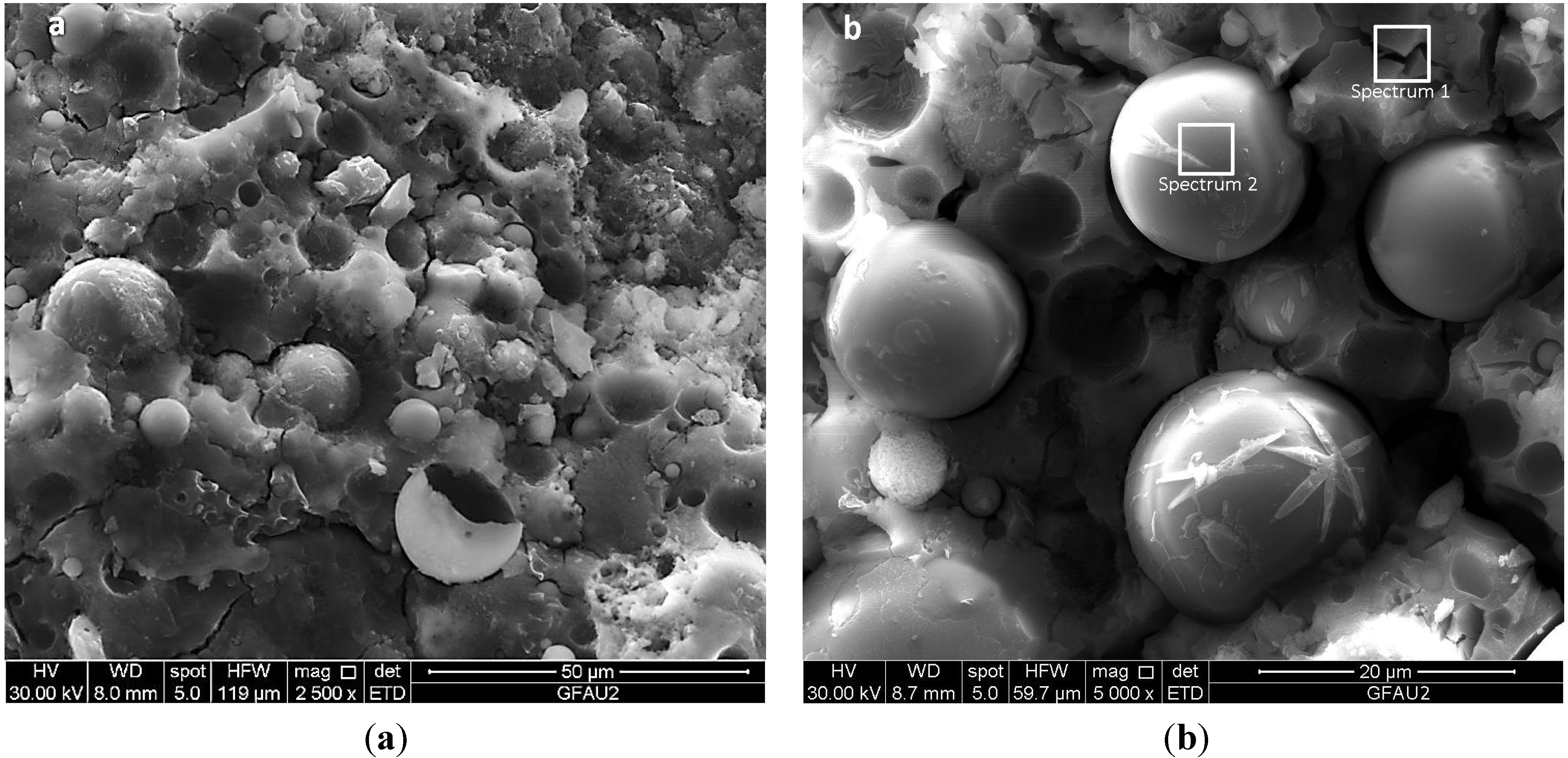
| Element | Weight % | Atomic % |
|---|---|---|
| C K | 4.69 | 7.52 |
| O K | 51.83 | 62.46 |
| Na K | 9.64 | 8.08 |
| Mg K | 0.38 | 0.30 |
| Al K | 7.04 | 5.03 |
| Si K | 20.41 | 14.01 |
| P K | 0.15 | 0.09 |
| S K | 0.21 | 0.13 |
| K K | 1.25 | 0.62 |
| Ca K | 1.31 | 0.63 |
| Ti K | 0.40 | 0.16 |
| Cr K | 1.20 | 0.45 |
| Fe K | 1.49 | 0.51 |
| Totals | 100.00 | - |
| Element | Weight % | Atomic % |
|---|---|---|
| O K | 54.82 | 68.60 |
| Na K | 1.60 | 1.40 |
| Mg K | 0.22 | 0.18 |
| Al K | 12.99 | 9.64 |
| Si K | 25.05 | 17.85 |
| K K | 2.14 | 1.09 |
| Ca K | 0.17 | 0.09 |
| Ti K | 0.76 | 0.32 |
| Cr K | 1.02 | 0.39 |
| Fe K | 1.23 | 0.44 |
| Totals | 100.00 | - |

3. Measurement of Vapor Permeability and of Thermal Properties
4. The Mathematical Model


5. Results
| Concrete mixture | Thermal conductivity λ (W/(m·K)) | Vapor permeability δ·1012 (kg/(m·s·Pa)) | Skeleton density ρ (kg/m3) | Specific heat capacity c (J/(kg·K)) |
|---|---|---|---|---|
| C0 | 1.42 | 7.97 | 2094 | 722 |
| C10 | 1.18 | 40.1 | 1914 | 743 |
| C15 | 1.07 | 34.9 | 1835 | 756 |
| C20 | 0.94 | 30.4 | 1762 | 766 |
| C25 | 0.82 | 27.8 | 1661 | 779 |
| C30 | 0.71 | 25.1 | 1518 | 789 |
| G | 1.01 | 32.8 | 1811 | 751 |
| Material | Reference | Thermal conductivity λ (W/(m·K)) | Vapor permeability δ·1012 (kg/(m·s·Pa)) | Density ρ (kg/m3) | Specific heat capacity c (J/(kg·K)) | Thickness s (m) |
|---|---|---|---|---|---|---|
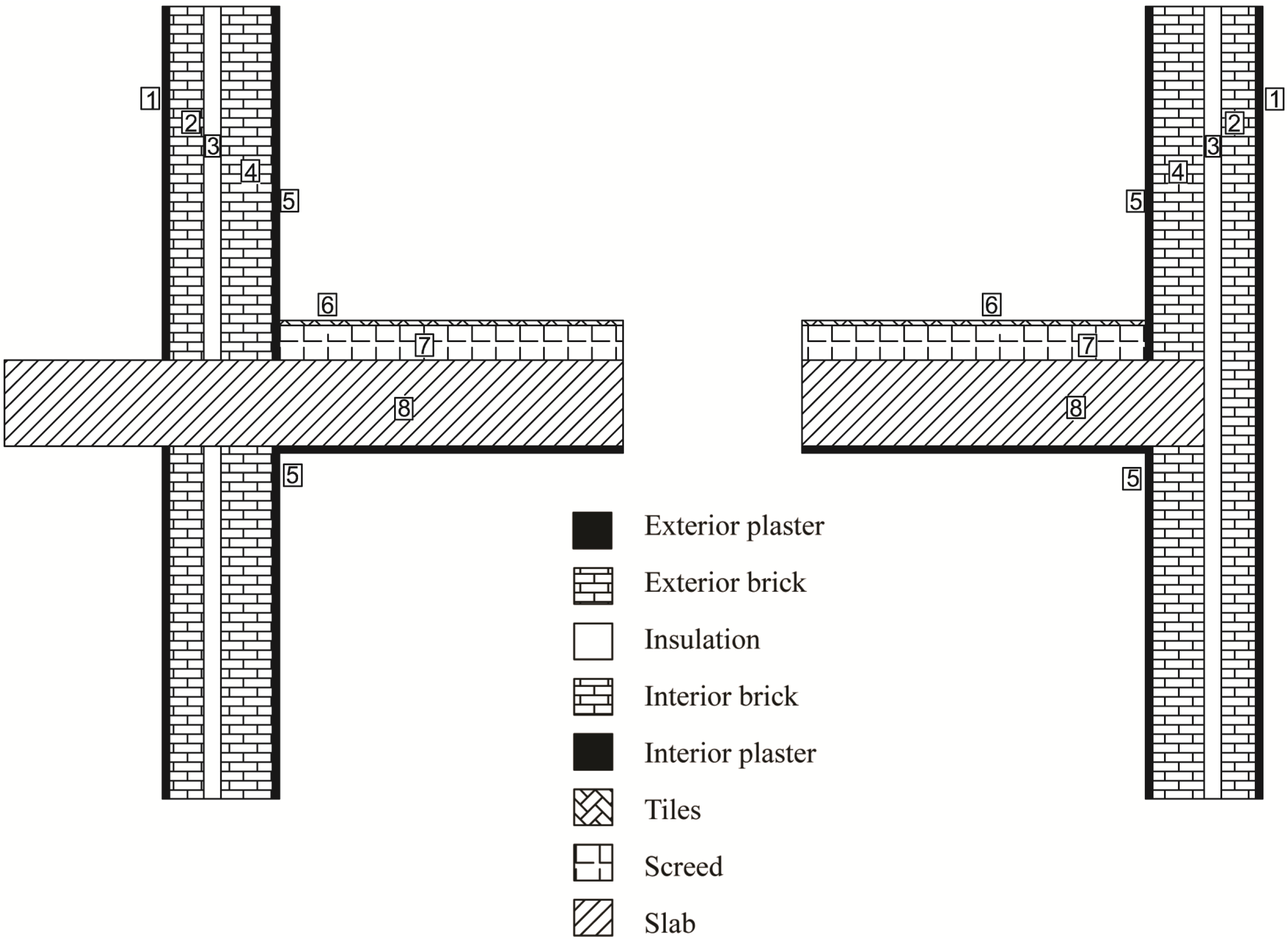
| Exterior plaster | n.1 in Figure 6 | 1.4 | 9.0 | 2000 | 1000 | 0.02 |
| Exterior Brick | n.2 in Figure 6 | 0.50 | 27 | 1400 | 840 | 0.10 |
| Insulation | n.3 in Figure 6 | 0.050 | 5.0 | 15 | 1250 | 0.05 |
| Interior Brick | n.4 in Figure 6 | 0.50 | 27 | 1400 | 840 | 0.15 |
| Interior plaster | n.5 in Figure 6 | 0.40 | 18 | 1000 | 1000 | 0.02 |
| Tiles | n.6 in Figure 6 | 1.30 | 9.0 | 2000 | 800 | 0.015 |
| Screed | n.7 in Figure 6 | Table 5 | Table 5 | Table 5 | Table 5 | 0.10 |
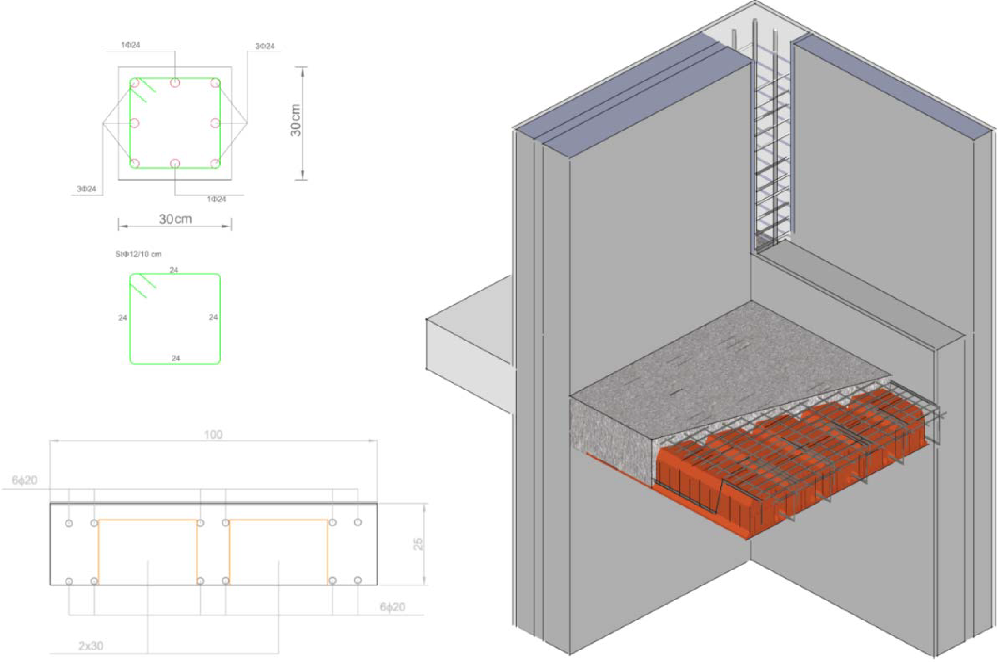
| Slab | n.8 in Figure 6; Figure 3 | Table 5 | Table 5 | Table 5 | Table 5 | 0.25 |
| Column | Figure 3 | Table 5 | Table 5 | Table 5 | Table 5 | 0.30 |
| Steel-framework | Figure 3 | 50 | 0 | 7500 | 385 | Figure 3 |

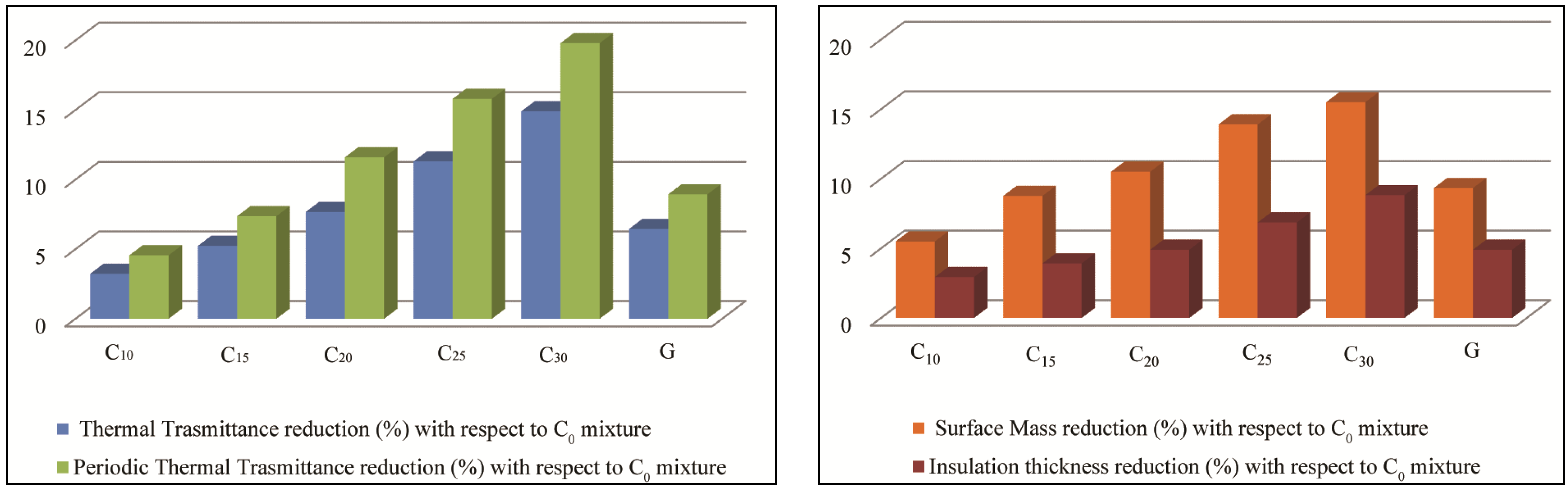
5.1. Reduction of Thermal Transmittance, Periodic Thermal Transmittance and Weight
| Concrete mixture | Thermal transmittance W/(m2·K) | Percentage reduction (%) | Periodic thermal transmittance W/(m2·K) | Percentage reduction (%) |
|---|---|---|---|---|
| C0 | 2.48 | - | 0.570 | - |
| C10 | 2.40 | 3.23 | 0.544 | 4.56 |
| C15 | 2.35 | 5.24 | 0.528 | 7.37 |
| C20 | 2.29 | 7.67 | 0.504 | 11.6 |
| C25 | 2.20 | 11.3 | 0.480 | 15.8 |
| C30 | 2.11 | 14.9 | 0.457 | 19.8 |
| G | 2.32 | 6.45 | 0.519 | 8.94 |
| Concrete mixture | Surface mass (kg/m2) | Percentage reduction (%) | Insulation thickness (m) | Percentage reduction (%) |
|---|---|---|---|---|
| C10 | 1185 | 5.50 | 0.099 | 2.94 |
| C15 | 1144 | 8.77 | 0.098 | 3.92 |
| C20 | 1123 | 10.5 | 0.097 | 4.90 |
| C25 | 1080 | 13.9 | 0.095 | 6.86 |
| C30 | 1060 | 15.5 | 0.093 | 8.82 |
| G | 1137 | 9.33 | 0.097 | 4.90 |

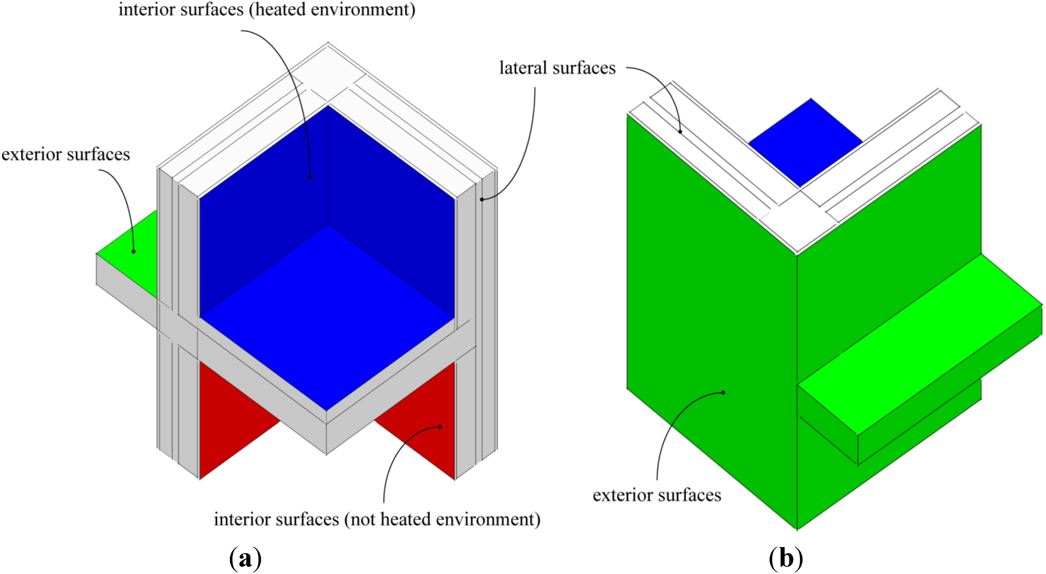
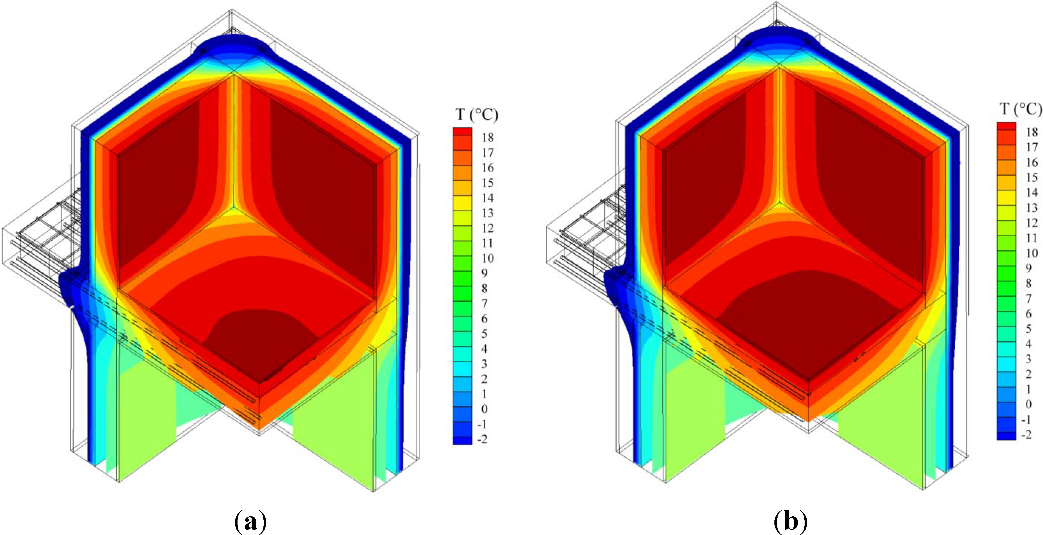
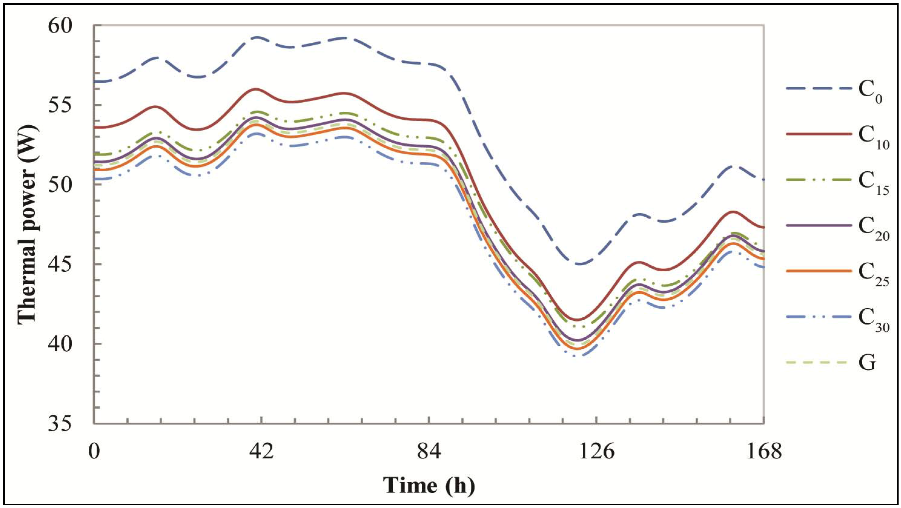
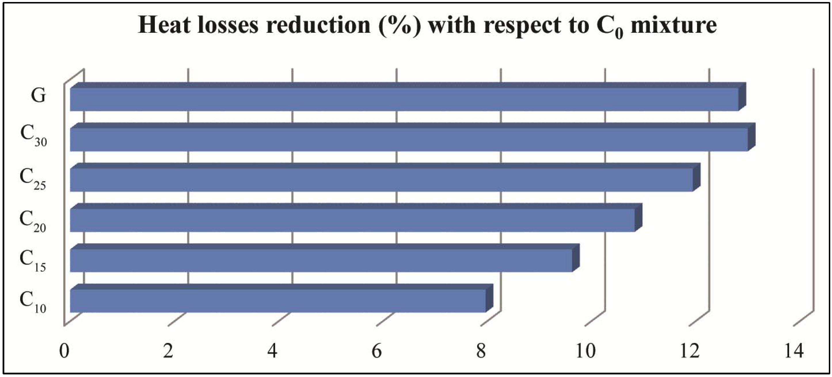
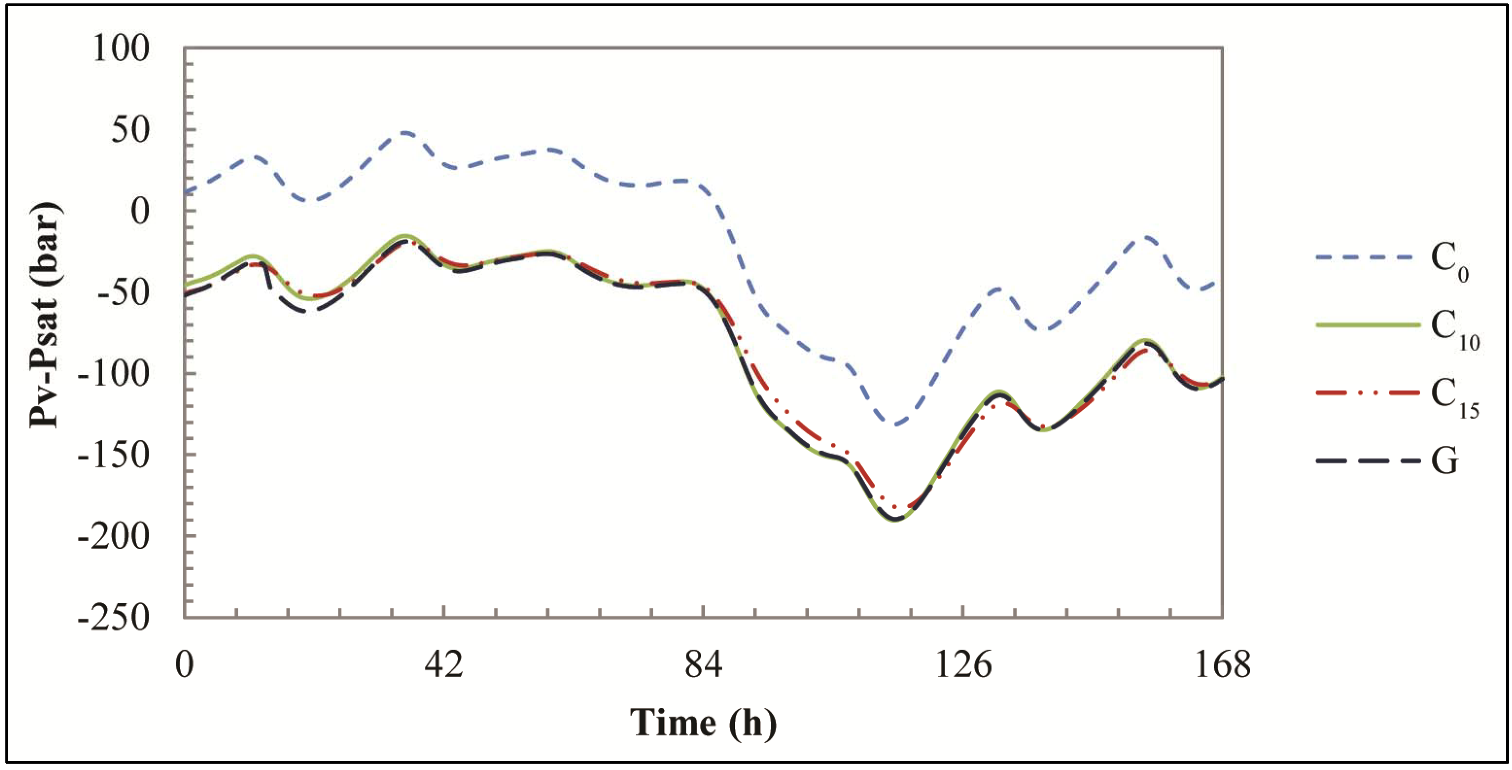
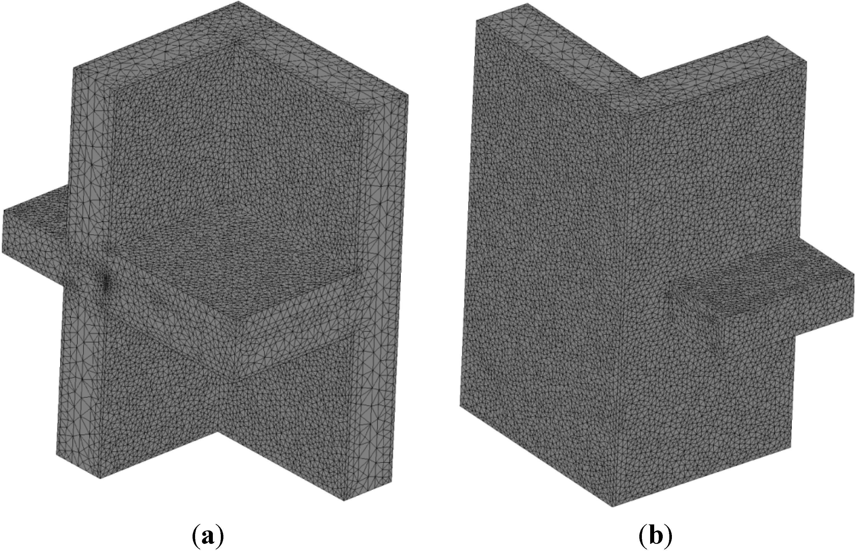
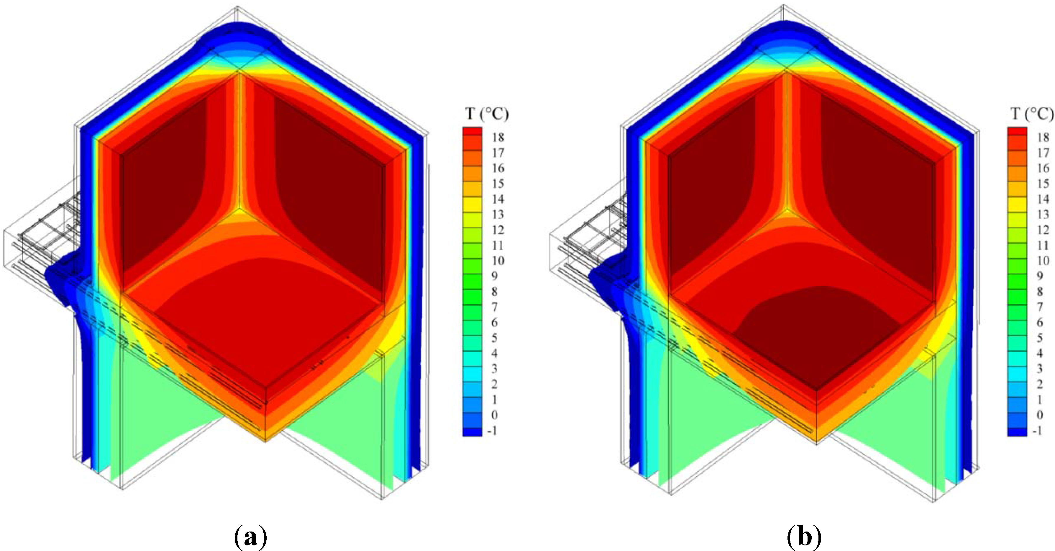
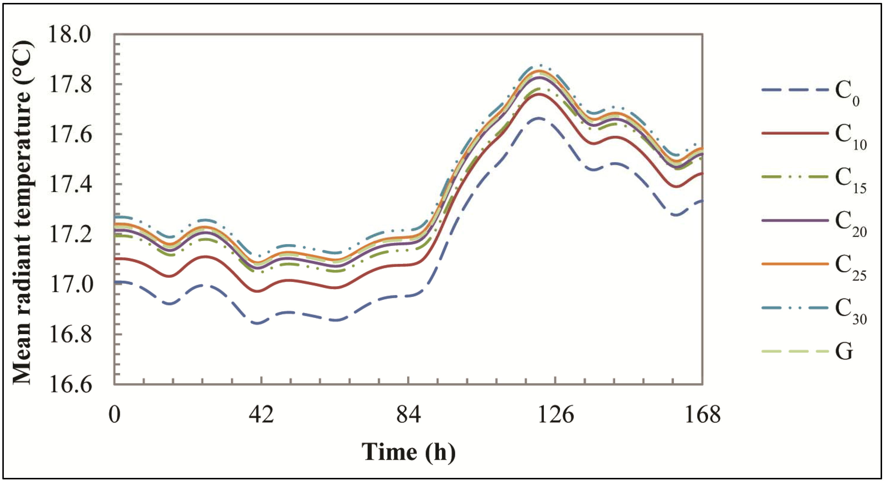
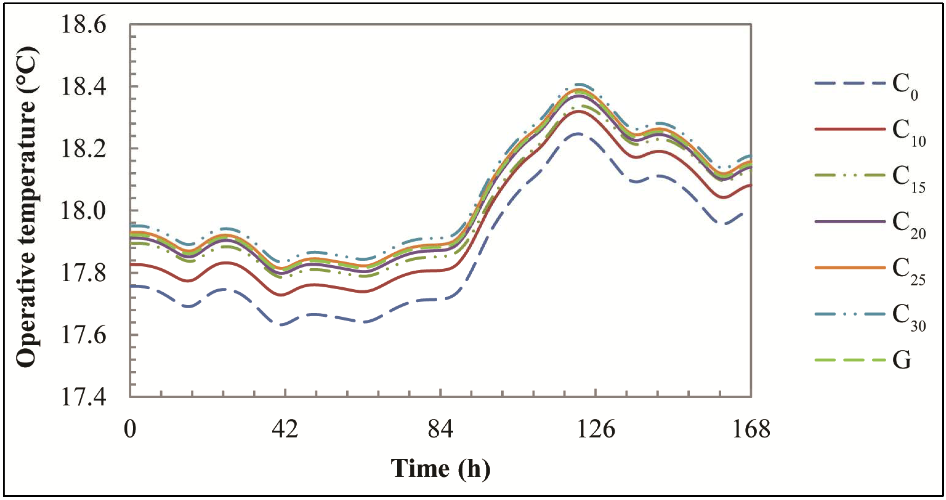
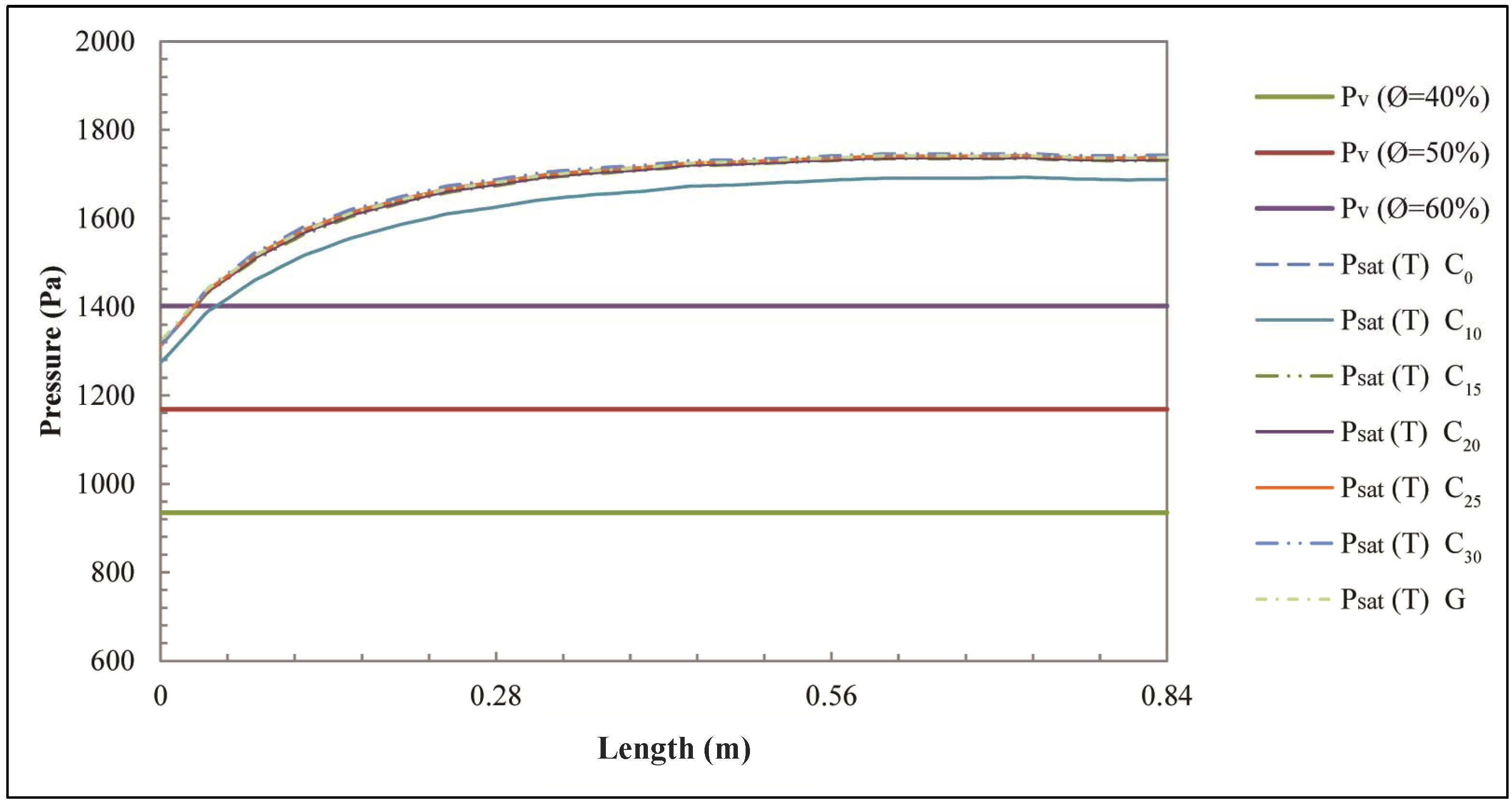
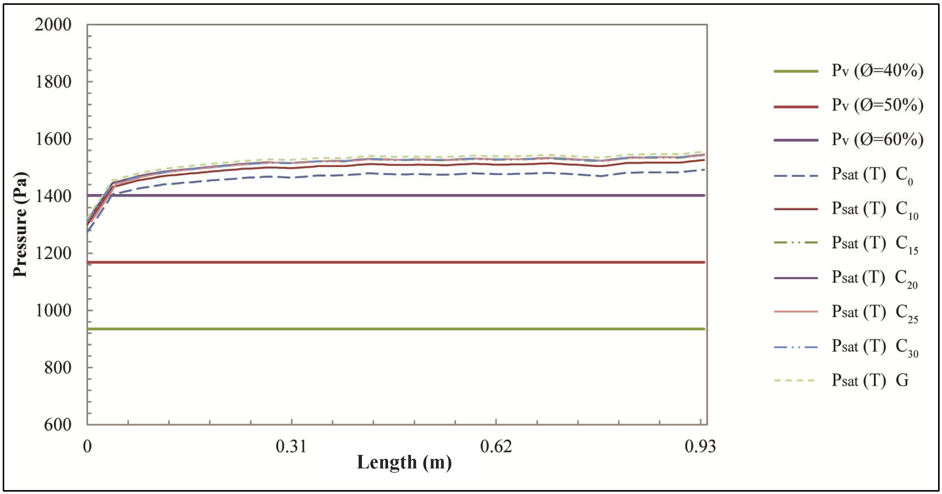
5.2. Dynamic Heat and Mass Transfer in a 3D Structure


6. Conclusions
Conflicts of Interest
Nomenclature
| c | specific heat capacity (J/kg·K) |
| C0–30 | concrete mixture (numbers from 0 to 30 indicate the percentage of recycled plastic) |
| G | geopolymeric concrete |
| hc | convective heat transfer coefficient (J/kg·K) |
| pv | partial pressure of vapor (Pa) |
| psat(T) | saturation pressure of water at temperature T (Pa) |
heat flux (W/m2) | |
| s | thickness (m) |
| T | temperature (K) |
| TP | surface temperature (K) |
| T∞ | environment temperature (K) |
Greek Symbols
| δ | water vapor permeability (kg/(m·s·Pa)) |
| λ | thermal conductivity (W/(m·K)) |
| ϕ | relative humidity |
| ρ | density (kg/m3) |
| ϑ | time (s) |
Subscripts
| 0 | initial |
| b | bricks |
| co | concrete |
| e | exterior |
| eq | equivalent |
| i | interior |
| s | steel |
| v | vapor |
| w | water |
References
- Siddique, R.; Khatib, J.; Kaur, I. Use of recycled plastic in concrete: A review. Waste Manag. 2008, 28, 1835–1852. [Google Scholar] [CrossRef] [PubMed]
- Italian Government. Environmental Regulations; Legislative Decree n. 152 of 3 April 2006; Italian Official Gazette: Rome, Italy, 2006.
- Li, G.; Lamberti, M.; Roviello, G.; Pellecchia, C. New titanium and hafnium complexes bearing [-NNN-] pyrrolylpyridylamido ligands as olefin polymerization catalysts. Organometallics 2012, 31, 6772–6778. [Google Scholar] [CrossRef]
- De Roma, A.; Yang, H.-J.; Milione, S.; Capacchione, C.; Roviello, G.; Grassi, A. Atom transfer radical polymerization of methylmethacrylate mediated by a naphtyl-nickel(II) phosphane complex. Inorg. Chem. Commun. 2011, 14, 542–544. [Google Scholar]
- Roviello, A.; Buono, A.; Carella, A.; Roviello, G.; Cassinese, A.; Barra, M.; Biasucci, M. Regioregular poly[3-(4-alkoxyphenyl)thiophene]s. J. Polym. Sci. Part A Polym. Chem. 2007, 45, 1758–1770. [Google Scholar] [CrossRef]
- Ferreira, L.; de Brito, J.; Saikia, N. Influence of curing conditions on the mechanical performance of concrete containing recycled plastic aggregate. Constr. Build. Mater. 2012, 36, 196–204. [Google Scholar] [CrossRef]
- Colangelo, F.; Cioffi, R.; Montagnaro, F.; Santoro, L. Soluble salt removal from MSWI fly ash and its stabilization for safer disposal and recovery as road basement material. Waste Manag. 2012, 32, 1179–1185. [Google Scholar] [CrossRef]
- Colangelo, F.; Cioffi, R.; Lavorgna, M.; Verdolotti, L.; De Stefano, L. Treatment and recycling of asbestos-cement containing waste. J. Hazard. Mater. 2011, 195, 391–397. [Google Scholar] [CrossRef] [PubMed]
- Cioffi, R.; Colangelo, F.; Montagnaro, F.; Santoro, L. Manufacture of artificial aggregate using MSWI bottom ash. Waste Manag. 2011, 31, 281–288. [Google Scholar] [CrossRef] [PubMed]
- Iucolano, F.; Liguori, B.; Caputo, D.; Colangelo, F.; Cioffi, R. Recycled plastic aggregate in mortars composition: Effect on physical and mechanical properties. Mater. Design 2013, 52, 916–922. [Google Scholar] [CrossRef]
- Mun, K.J. Development and tests of lightweight aggregate using sewage sludge for nonstructural concrete. Constr. Build. Mater. 2007, 21, 1583–1588. [Google Scholar] [CrossRef]
- Chang, F.-C.; Lee, M.-Y.; Lo, S.-L.; Lin, J.-D. Artificial aggregate made from waste stone sludge and waste silt. J. Environ. Manag. 2010, 91, 2289–2294. [Google Scholar] [CrossRef]
- Behiry, A.E.A.E.-M. Utilization of cement treated recycled concrete aggregates as base or subbase layer in Egypt. Ain Shams Eng. J. 2013, 4, 661–673. [Google Scholar] [CrossRef]
- Ismail, S.; Ramli, M. Engineering properties of treated recycled concrete aggregate (RCA) for structural applications. Constr. Build. Mater. 2013, 44, 464–476. [Google Scholar] [CrossRef]
- Mahdi, F.; Abbas, H.; Khan, A.A. Flexural, shear and bond strength of polymer concrete utilizing recycled resin obtained from post consumer PET bottles. Constr. Build. Mater. 2013, 44, 798–811. [Google Scholar] [CrossRef]
- Jo, B.-W.; Park, S.-K.; Park, J.-C. Mechanical properties of polymer concrete made with recycled PET and recycled concrete aggregates. Constr. Build. Mater. 2008, 22, 2281–2291. [Google Scholar] [CrossRef]
- Xiao, J.; Huang, Y.; Yang, J.; Zhang, C. Mechanical properties of confined recycled aggregate concrete under axial compression. Constr. Build. Mater. 2012, 26, 591–603. [Google Scholar] [CrossRef]
- Fraternali, F.; Ciancia, V.; Chechile, R.; Rizzano, G.; Feo, L.; Incarnato, L. Experimental study of the thermo-mechanical properties of recycled PET fiber-reinforced concrete. Compos. Struct. 2011, 93, 2368–2374. [Google Scholar] [CrossRef]
- Kim, S.B.; Yi, N.H.; Kim, H.Y.; Kim, J.-H.J.; Song, Y.-C. Material and structural performance evaluation of recycled PET fiber reinforced concrete. Cem. Concr. Compos. 2010, 32, 232–240. [Google Scholar] [CrossRef]
- Xiao, J.; Huang, X.; Shen, L. Seismic behavior of semi-precast column with recycled aggregate concrete. Constr. Build. Mater. 2012, 35, 988–1001. [Google Scholar] [CrossRef]
- Duxson, P.; Fernandez-Jimenez, A.; Provis, J.L.; Lukey, G.C.; Palomo, A.; van Deventer, J.S.J. Geopolymer technology: The current state of art. J. Mater. Sci. 2007, 42, 2917–2933. [Google Scholar] [CrossRef]
- Cioffi, R.; Maffucci, L.; Santoro, L. Optimization of geopolymer synthesis by calcination and polycondensation of a Kaolinitic residue. Resour. Conserv. Recycl. 2003, 40, 27–38. [Google Scholar] [CrossRef]
- Ferone, C.; Roviello, G.; Colangelo, F.; Cioffi, R.; Tarallo, O. Novel hybrid organic-geopolymer materials. Appl. Clay Sci. 2013, 73, 42–50. [Google Scholar] [CrossRef]
- Colangelo, F.; Roviello, G.; Ricciotti, L.; Ferone, C.; Cioffi, R. Preparation and characterization of new geopolymer-epoxy resin hybrid mortars. Materials 2013, 6, 2989–3006. [Google Scholar] [CrossRef]
- Ferone, C.; Colangelo, F.; Cioffi, R.; Montagnaro, F.; Santoro, L. Use of reservoir clay sediments as raw materials for geopolymer binders. Adv. Appl. Ceram. 2013, 112, 184–189. [Google Scholar] [CrossRef]
- Xu, H.; van Deventer, J.S.J. The geopolymerisation of alumino-silicate minerals. Int. J. Miner. Process. 2000, 59, 247–266. [Google Scholar] [CrossRef]
- Andini, S.; Cioffi, R.; Colangelo, F.; Grieco, T.; Montagnaro, F.; Santoro, L. Coal fly ash as raw material for the manufacture of geopolymer-based products. Waste Manag. 2008, 28, 416–423. [Google Scholar] [CrossRef] [PubMed]
- Andini, S.; Cioffi, R.; Colangelo, F.; Ferone, C.; Montagnaro, F.; Santoro, L. Characterization of geopolymer materials containing MSWI fly ash and coal fly ash. Adv. Sci. Technol. 2010, 69, 123–128. [Google Scholar] [CrossRef]
- Ferone, C.; Colangelo, F.; Cioffi, R.; Montagnaro, F.; Santoro, L. Mechanical performances of weathered coal fly ash based geopolymer bricks. Procedia Eng. 2011, 21, 745–752. [Google Scholar] [CrossRef]
- Komnitsas, K.; Zaharaki, D.; Perdikatsis, V. Geopolymerisation of low calcium ferronickel slags. J. Mater. Sci. 2007, 42, 3073–3082. [Google Scholar] [CrossRef]
- Duxson, P.; Lukey, G.C.; van Deventer, J.S.J. Physical evolution of Na-geopolymer derived from metakaolin up to 1000 °C. J. Mater. Sci. 2007, 42, 3044–3054. [Google Scholar] [CrossRef]
- Menna, C.; Asprone, D.; Ferone, C.; Colangelo, F.; Balsamo, A.; Prota, A.; Cioffi, R.; Manfredi, G. Use of geopolymers for composite external reinforcement of RC members. Compos. Part B 2013, 45, 1667–1676. [Google Scholar] [CrossRef]
- Ferone, C.; Colangelo, F.; Roviello, G.; Cioffi, R.; Menna, C.; Asprone, D.; Balsamo, A.; Prota, A.; Manfredi, G. Application-oriented chemical optimization of a metakaolin based geopolymer. Materials 2013, 6, 1920–1939. [Google Scholar] [CrossRef] [Green Version]
- Palomo, A.; Blanco-Varela, M.T.; Granizo, M.L.; Puertas, F.; Vasquez, T.; Grutzeck, M.W. Chemical stability of cementitious materials based on metakaolin. Cem. Concr. Res. 1999, 29, 997–1004. [Google Scholar] [CrossRef]
- Habert, G.; d’Espinose de Lacaillerie, J.B.; Roussel, N. An environmental evaluation of geopolymer based concrete production: Reviewing current research trends. J. Cleaner Prod. 2011, 19, 1229–1238. [Google Scholar] [CrossRef]
- Davidovits, J. Geopolymer, Chemistry and Applications, 3rd ed.; Institute Geopolymer: Saint-Quentin, France, 2011; pp. 10–11. [Google Scholar]
- European Community. Directive 2002/91/EC of the European Parliament and of the Council of 16 December 2002 on the energy performance of buildings. Off. J. Eur. Commun. 2003, L1, 65–71. [Google Scholar]
- European Union. Directive 2012/27/EU of the European Parliament and of the Council of 25 October 2012 on energy efficiency, amending Directives 2009/125/EC and 2010/30/EU and repealing Directives 2004/8/EC and 2006/32/EC. Off. J. Eur. Union 2012, L315, 1–56. [Google Scholar]
- European Union. Directive 2010/31/EU of the European Parliament and of the Council of 19 May 2010 on the energy performance of buildings (recast). Off. J. Eur. Union 2010, L153, 13–35. [Google Scholar]
- Italian Government. Regulation for the Implementation of Article 4, Paragraph 1, Letters a) and b) of Legislative Decree 19 August 2005, n. 192, Concerning the Implementation of Directive 2002/91/EC on the Energy Performance of Buildings; Presidential Decree n. 59 of 2 April 2009; Italian Official Gazette: Rome, Italy, 2009.
- Italian Government. Implementation of Directive 2002/91/EC on the Energy Performance of Buildings; Legislative Decree n. 192 of 19 August 2005; Italian Official Gazette: Rome, Italy, 2005.
- Italian Government. Corrective and Supplementary Provisions to the Legislative Decree 19 August 2005, n. 192, Implementing Directive 2002/91/EC on the Energy Performance of Buildings; Legislative Decree n. 311 of 29 December 2006; Italian Official Gazette: Rome, Italy, 2007.
- Arpino, F.; Massarotti, N.; Mauro, A.; Nithiarasu, P. Artificial compressibility based CBS solutions for double diffusive natural convection in cavities. Int. J. Numer. Methods Heat Fluid Flow 2013, 23, 205–225. [Google Scholar] [CrossRef]
- Arpino, F.; Carotenuto, A.; Massarotti, N.; Mauro, A. New solutions for axial flow convection in porous and partly porous cylindrical domains. Int. J. Heat Mass Transf. 2013, 57, 155–170. [Google Scholar] [CrossRef]
- Carotenuto, A.; Massarotti, N.; Mauro, A. A new methodology for numerical simulation of geothermal down-hole heat exchangers. Appl. Therm. Eng. 2012, 48, 225–236. [Google Scholar]
- Arpino, F.; Massarotti, N.; Mauro, A. Efficient three-dimensional FEM based algorithm for the solution of convection in partly porous domains. Int. J. Heat Mass Transf. 2011, 54, 4495–4506. [Google Scholar] [CrossRef]
- Mauro, A.; Arpino, F.; Massarotti, N. Three-dimensional simulation of heat and mass transport phenomena in planar SOFCs. Int. J. Hydrog. Energy 2011, 36, 10288–10301. [Google Scholar] [CrossRef]
- Mauro, A.; Arpino, F.; Massarotti, N.; Nithiarasu, P. A novel single domain approach for numerical modelling solid oxide fuel cells. Int. J. Numer. Methods Heat Fluid Flow 2010, 20, 587–612. [Google Scholar] [CrossRef]
- European Committee for Standardization (CEN). Part 1: Composition, Specifications and Conformity Criteria for Common Cements. In Cement; European Standard, EN 197-1:2011; CEN: Brussels, Belgium, 2011. [Google Scholar]
- European Committee for Standardization (CEN). Part 1: Specification, Performance, Production and Conformity. In Concrete; European Standard, UNI EN 206-1:2006; CEN: Brussels, Belgium, 2006. [Google Scholar]
- Fernandez-Jimenez, A.; Palomo, A. Nanostructure/Microstructure of Fly Ash Geopolymers. In Geopolymers: Structure, Processing, Properties and Industrial Applications; Provis, J.L., van Deventer, J.S.J., Eds.; CRC Press/Taylor and Francis: Boca Raton, FL, USA, 2009; pp. 89–117. [Google Scholar]
- European Committee for Standardization (CEN). Part 19: Determination of Water Vapour Permeability of Hardened Rendering and Plastering Mortars. In Methods of Test for Mortar for Masonry; European Standard, UNI EN 1015-19:2008; CEN: Brussels, Belgium, 2008. [Google Scholar]
- Zienkiewicz, O.C.; Taylor, R.L.; Nithiarasu, P. The Finite Element Method for Fluid Dynamics, 6th ed.; Elsevier Butterworth-Heinemann: Oxford, UK, 2005. [Google Scholar]
- Lewis, R.W.; Nithiarasu, P.; Seetharamu, K.N. Fundamentals of the Finite Element Method for Heat and Fluid Flow; John Wiley & Sons: Chichester, England, UK, 2004. [Google Scholar]
- International Organization for Standardization (ISO). Hygrothermal Performance of Building Components and Building Elements—Internal Surface Temperature to Avoid Critical Surface Humidity and Interstitial Condensation—Calculation Methods; International Standard, UNI EN ISO 13788:2003; ISO: Geneva, Switzerland, 2003. [Google Scholar]
- International Organization for Standardization (ISO). Thermal Bridges in Building Construction—Heat Flows and Surface Temperatures—Detailed Calculation; International Standard, UNI EN ISO 10211:2008; ISO: Geneva, Switzerland, 2008. [Google Scholar]
- Ente Nazionale Italiano di Unificazione (UNI). Materiali da Costruzione—Conduttività Termica e Permeabilità al Vapore (in Italian); Italian Standard, UNI 10351:1994; UNI: Milan, Italy, 1994. [Google Scholar]
- European Committee for Standardization (CEN). Building Materials and Products—Hygrothermal Properties—Tabulated Design Values; European Standard, UNI EN 12524:2001; CEN: Brussels, Belgium, 2001. [Google Scholar]
- International Organization for Standardization (ISO). Building Materials and Products—Hygrothermal Properties—Tabulated Design Values and Procedures for Determining Declared and Design Thermal Values; International Standard, UNI EN ISO 10456:2008; ISO: Geneva, Switzerland, 2008. [Google Scholar]
- International Organization for Standardization (ISO). Building Components and Building Elements—Thermal Resistance and Thermal Transmittance—Calculation Method; International Standard, UNI EN ISO 6946:2008; ISO: Geneva, Switzerland, 2008. [Google Scholar]
- International Organization for Standardization (ISO). Thermal Performance of Building Components—Dynamic Thermal Characteristics—Calculation Methods; International Standard, UNI EN ISO 13786:2007; ISO: Geneva, Switzerland, 2007. [Google Scholar]
- International Organization for Standardization (ISO). Part 4: Hourly Data for Assessing the Annual Energy Use for Heating and Cooling. In Hygrothermal Performance of Buildings—Calculation and Presentation of Climatic Data; International Standard, UNI EN ISO 15927-4:2005; ISO: Geneva, Switzerland, 2005. [Google Scholar]
- International Organization for Standardization (ISO). Ergonomics of the Thermal Environment—Analytical Determination and Interpretation of Thermal Comfort Using Calculation of the PMV and PPD Indices and Local Thermal Comfort Criteria; International Standard, ISO 7730:2005; ISO: Geneva, Switzerland, 2005. [Google Scholar]
- International Organization for Standardization (ISO). Ergonomics of the Thermal Environment—Instruments for Measuring Physical Quantities; International Standard, UNI EN ISO 7726:2002; ISO: Geneva, Switzerland, 2002. [Google Scholar]
- American Society of Heating, Refrigerating and Air-Conditioning Engineers, Inc. (ASHRAE). Thermal Comfort. In ASHRAE Handbook—Fundamentals; ASHRAE: Atlanta, GA, USA, 2009; Chapter 9. [Google Scholar]
© 2013 by the authors; licensee MDPI, Basel, Switzerland. This article is an open access article distributed under the terms and conditions of the Creative Commons Attribution license (http://creativecommons.org/licenses/by/3.0/).
Share and Cite
Colangelo, F.; De Luca, G.; Ferone, C.; Mauro, A. Experimental and Numerical Analysis of Thermal and Hygrometric Characteristics of Building Structures Employing Recycled Plastic Aggregates and Geopolymer Concrete. Energies 2013, 6, 6077-6101. https://doi.org/10.3390/en6116077
Colangelo F, De Luca G, Ferone C, Mauro A. Experimental and Numerical Analysis of Thermal and Hygrometric Characteristics of Building Structures Employing Recycled Plastic Aggregates and Geopolymer Concrete. Energies. 2013; 6(11):6077-6101. https://doi.org/10.3390/en6116077
Chicago/Turabian StyleColangelo, Francesco, Giuseppina De Luca, Claudio Ferone, and Alessandro Mauro. 2013. "Experimental and Numerical Analysis of Thermal and Hygrometric Characteristics of Building Structures Employing Recycled Plastic Aggregates and Geopolymer Concrete" Energies 6, no. 11: 6077-6101. https://doi.org/10.3390/en6116077