Article

Evaluation and Optimization of a Traditional North-Light Roof on Industrial Plant Energy Consumption

1
Form-Finding Lab, Department of Civil and Environmental Engineering, School of Engineering and Applied Science, Engineering Quadrangle-E 332, Princeton University, Princeton, NJ 08544, USA
2
Center for Intelligent and Networked Systems, Department of Automation, Tsinghua National Laboratory for Information Science and Technology, Tsinghua University, Beijing 100084, China
*
Author to whom correspondence should be addressed.
Energies 2013, 6(4), 1944-1960; https://doi.org/10.3390/en6041944
Submission received: 28 December 2012 / Revised: 2 March 2013 / Accepted: 6 March 2013 / Published: 3 April 2013
(This article belongs to the Special Issue Energy Efficient Buildings and Green Buildings)

Abstract

:
Increasingly strict energy policies, rising energy prices, and a desire for a positive corporate image currently serve as incentives for multinational corporations to reduce their plants’ energy consumption. This paper quantitatively investigates and discusses the value of a traditional north-light roof using a complete building energy simulation and optimization framework. The findings indicate that the north-light system yields positive building energy performance for several climate zones, including: (i) Humid Subtropical; (ii) Semiarid Continental; (iii) Mediterranean; and (iv) Subtropical Highland. In the Subtropical Highland climate zone, for example, the building energy consumption of a north-light roof is up to 54% less than that of a conventional flat roof. Based on these positive findings, this paper further presents an optimization framework that alters the north-light roof shape to further improve its energy performance. To quantitatively guarantee a high probability of finding satisfactory designs while reducing the computational processing time, ordinal optimization is introduced into the scheme. The Subtropical Highland case study shows further energy building consumption reduction of 26% for an optimized north-light roof shape. The presented evaluation and optimization framework could be used in designing a plant with integrated north-lights roof that aim at energy efficiency while maintaining environmental occupant comfort levels.

Graphical Abstract

1. Introduction: Socio-Industrial Context of Energy-Efficient Plant Design

By 2050, 67% of the World’s entire population will live in cities. This number will be closer to 86% in the largest urban agglomerations located in Japan, India, Mexico, USA, China, and Brazil [1]. To reduce production and transportation costs, multinationals create manufacturing plants in urban areas with a significant demand for their products [2]. As the need for industry increases, so does the impact of industrial energy consumption. Increasingly strict energy policies, rising energy prices, and a desire for a positive corporate image serve as incentives for multinationals to regulate their energy consumption. Soft energy saving measures—such as training staff to adopt energy conservation habits and off-peak electricity shift patterns—yield instant results [3,4]. Little research however has been done on controlling and optimizing energy consumption in industrial plants beyond these soft measures. Currently, most plants do not incorporate energy conservation and efficiency features into their designs, and thus have high operational energy consumption and are not designed to maintain a comfortable indoor climate for their labor force [5]. Since the lighting load in an industrial plant can account for up to 40% of all energy usage [6], the north-light roof, a traditional industrial roof system that brings diffuse lighting into the inner spaces of large buildings [7], might have a significant value in energy-efficient plant design [8,9].

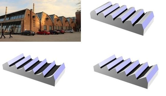
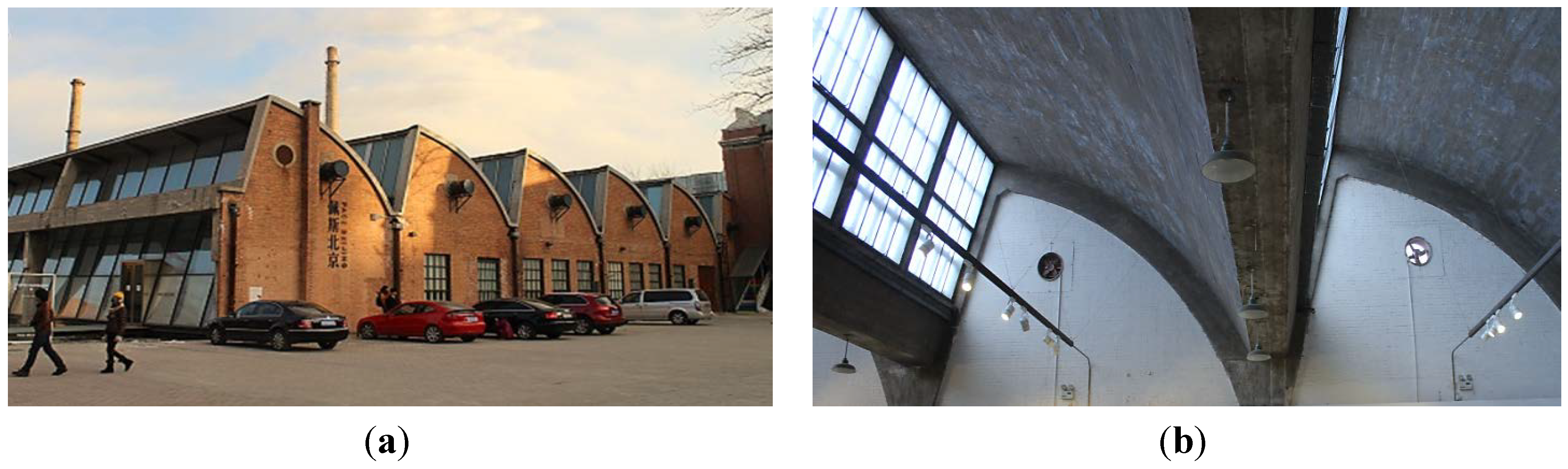
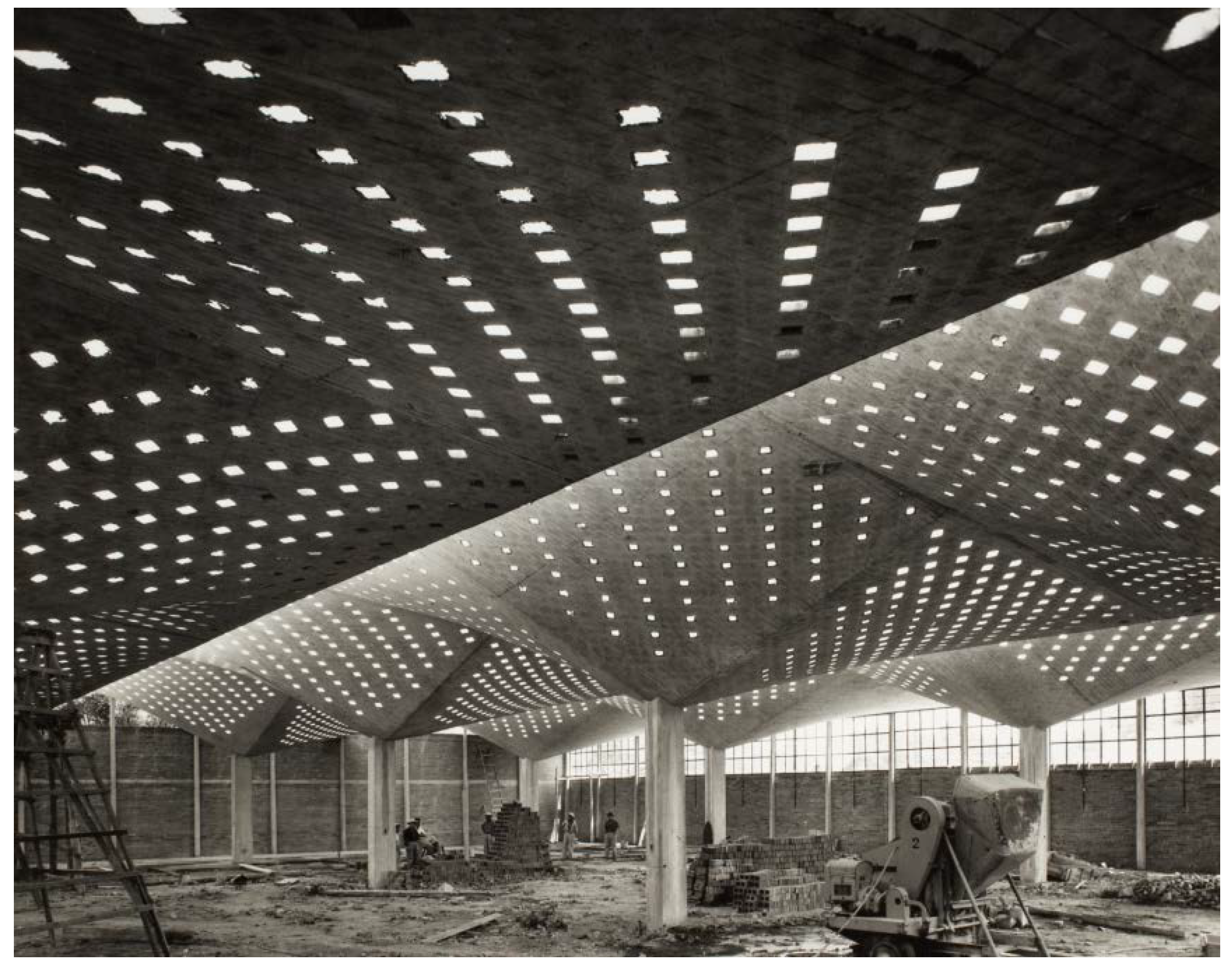
2. Context and Relevance of the North-Light Roof in Industrial Plant Buildings

In the absence of any form of affordable artificial lighting, early 19th century British textile factory owners faced a similar lighting challenge as 21st century multinationals: how to provide adequate constant and unvarying lighting levels to the work floor economically. The earliest textile plants were realized with very small windows on the lower levels to deter rioters and spies. When gas lighting became readily available, the windows in later textile mills occupied as much of the wall space as the structure would allow. At the end of the 19th century in Great Britain, large single story plants, erected to hold power looms, had skylights with vertical glass built into their roofs [10]. This early version of north-light roof typology brought passive solar building design benefits to industrial buildings. When Europe and the USA further industrialized, this north-light typology and its vaulted variations (concave and convex) spread, made possible in the early 20th century by the advent of reinforced concrete and pre-stressing [11]. During the 1940s and 1950s, advances in artificial lighting reduced the need for day lighting in plant design. In 1960 as few as 15% of newly built factories relied on day lighting [12]. Currently few industrial plants are designed with day lighting in mind [10]. The convex north-light roof, shown in Figure 1, has been a point of reference for this study. For all clarity, in the Northern Hemisphere, this configuration is called a north-light system: it brings diffuse light and high light levels to the space below without contrast. In the Southern Hemisphere, this is a south-light system, indicating the necessary orientation of the window panes with respect to the solar path.
Figure 1. (a) Exterior view of convex north-light roof system over the former Production Hall, Ammunition Factory, Beijing, China (1950s); (b) Interior view of same hall, rehabilitated in 2008 as the Pace Art Gallery, shows optimal use of diffuse north light to provide adequate lighting levels for previous bench work activities and currently display art work.
Energies 06 01944 g001
Although there are perceived benefits to using this type of roof lighting, few studies [13] have been carried out that suggest how to control the building energy consumption (including heating, cooling and lighting) of a plant with such a roof. Typical suggestions for energy conservation in industrial plant design relate to individual systems (e.g., increasing levels of daylight to reduce artificial lighting [14,15]; or setting up heat recovery systems where possible, etc.). These suggestions cover most areas of energy consumption in a plant, yet the effect of their interaction is not studied. Some of these suggestions may actually cause unexpected negative effects. For example, the north-light typologies increase the plant’s reliance on natural light, but at the cost of an increase in air volume, thus lowering artificial lighting levels but potentially increasing heating and cooling loads. There is also the consideration of heat loss through the north-lights, despite the gains in natural lighting.
Two questions arise from these considerations: (i) what value does the north-light typology have for industrial plant design that focuses on energy efficiency and worker’s thermal comfort? (ii) what framework can be adopted to optimize the north-light shape to achieve minimum total building energy consumption?
The remainder of this paper is organized as follows: Section 3 describes the energy consumption estimation framework and evaluates the building energy consumption of a typical single-volume plant with various roof configurations with integrated north-lights for five climate zones. Section 4 presents an optimization framework that optimizes the shape of the roof units with integrated north-lights with the objective of minimizing energy consumption while providing acceptable lighting levels and thermal comfort to workers.

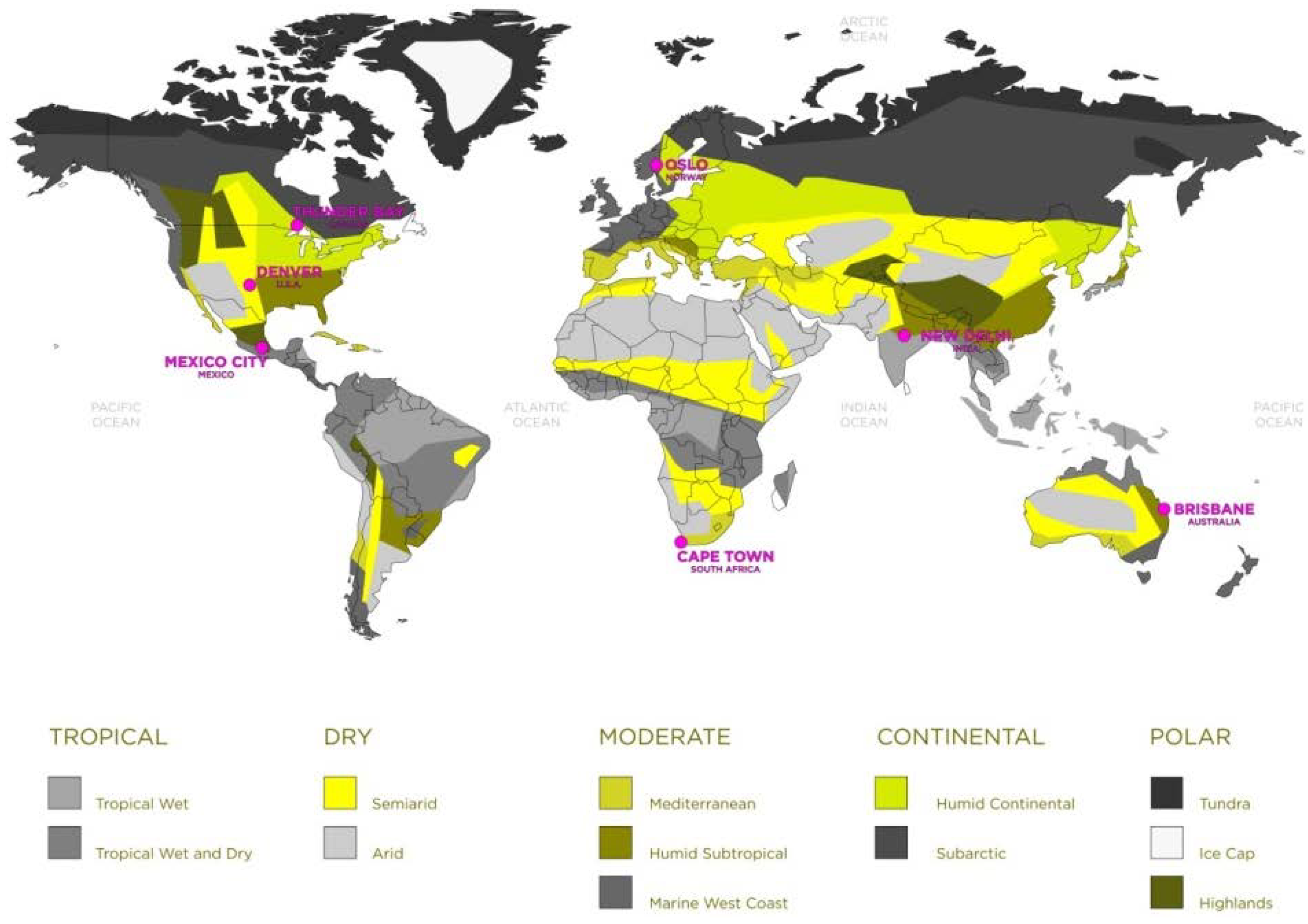
3. Plant Building Energy Consumption Simulation

The total energy consumption of a plant is divided into two parts: (i) the production processes’ energy consumption (i.e., energy consumed by the systems to make products); and (ii) the building energy consumption (i.e., energy consumed by the systems, such as HVAC and lighting, to maintain the required interior environmental conditions). Usually, the production processes’ energy consumption depends on parameters related to the production systems (such as the power of the manufacturing machines), and is thus independent of the building design. On the other hand the building energy consumption is closely related to the building envelope design, which can vary in form, orientation, partitions, and materials. The building envelope directly influences the energy required to heat or cool and illuminate the interior. For this reason, building energy consumption is chosen as the performance measurement in the optimization of the plant design. To estimate the performance of such a design, two sets of loads are determined: (i) thermal loads necessary to maintain the thermal control set points; and (ii) lighting energy needed to maintain the illuminance control set points of the interior environment. In other words, the building energy consumption due to HVAC and lighting is evaluated as the design’s performance, with the temperature and illuminance set points always being satisfied. Humidity and air quality conditioning are not considered. The evaluation is based on analyses run in the energy and thermal load simulation program EnergyPlus [16]. The weather data required for the simulations is obtained from the EnergyPlus website [16].

3.1. EnergyPlus Simulation Model

To evaluate the energy-savings of the traditional north-light configuration on the building energy consumption, analyses were carried out for the same plant design in seven major industrial centers located in five different climate zones worldwide in the Northern and Southern hemispheres. (Subtropical Highland: Mexico City, Mexico; Humid Subtropical: New Delhi, India and Brisbane, Australia; Semiarid Continental: Denver, USA; Mediterranean: Cape Town, South-Africa and Humid Continental: Thunder Bay, Canada and Oslo, Norway). The climate zones are chosen in function of altitude, latitude, wind and distance from the sea and are shown in Figure 2. The effect of concave and convex roof forms with integrated north-lights on the building energy consumption were investigated for all cases and compared with the energy consumption of a flat roof building with windows installed on the east and west walls.
Figure 2. Seven major industrial cities investigated in this study superimposed on the climate map.
Energies 06 01944 g002
The plant is housed in a single-story, single-volume building with typical dimensions [17]: the building’s length is 45 m, which is then divided into six adjacent 7.5m long units (with north-lights), the building’s width is 20.3 m, and the height of the building is 4.5 m. All of the models used in this analysis represent single-volume plants, meaning that the volumes of the individual roof lights (when present) are combined with the volume of the main room to achieve a single total volume. Therefore, the model containing no roof lights contains the smallest total volume, and the total volume of the plant increases with the addition of roof lights. The roof lights are oriented north in the northern hemisphere and south in the southern hemisphere. This configuration is referred to as a “north-light” configuration throughout this paper for ease of reference, although in the simulations the configuration changes its orientation depending on its geographical location with respect to the equator. A typical build-up for the floor, walls, roof and windows is given in Table 1.
Table 1. Build-up of the plant envelope from the exterior to the interior.
ElementLayer 1Layer 2Layer 3
Floor150 cm soil10 cm concrete-
Wall1 cm concrete 1–4 dry block11 cm concrete cinder block1 cm gypsum plaster
Window6 mm low emissivity glass3 mm air gap6 mm low emissivity glass
Roof6 mm asphalt cover15 cm concrete1 cm gypsum plaster
The building has day-lighting controls with two illuminance set points of 500 lux [17] along the median line of the building’s length and at a distance of length/3 from the north and south wall at a height of 1.2 m as shown in Figure 3. The temperature is controlled within a range of 18 to 26 °C [18]. These illuminance and temperature controls are valid for a typical working day from 8 am to 6 pm for one annual cycle. The analyses were run using a 10 min time step.
Figure 3. Generic geometric model for the environmental performance analyses.
Energies 06 01944 g003

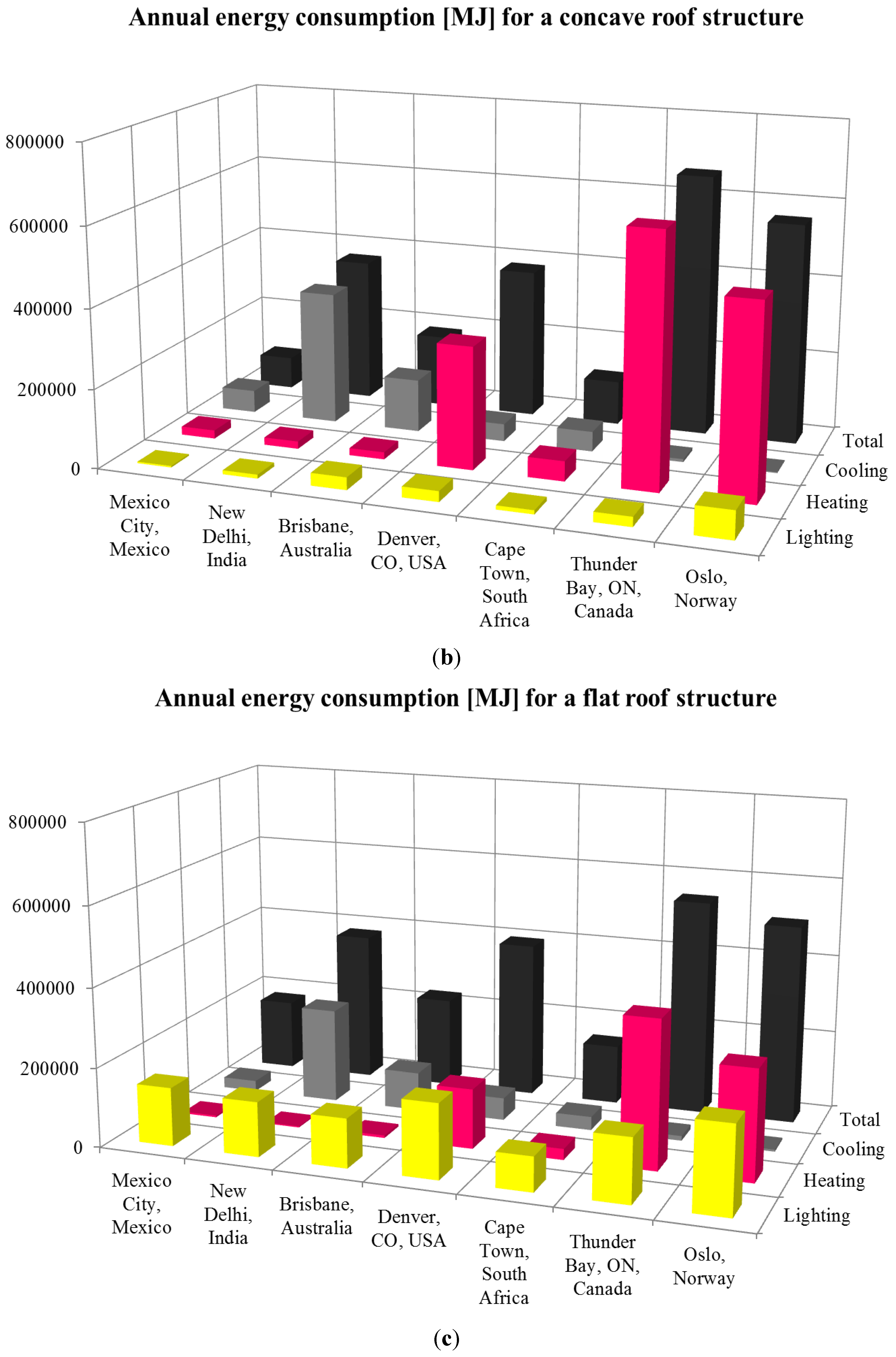
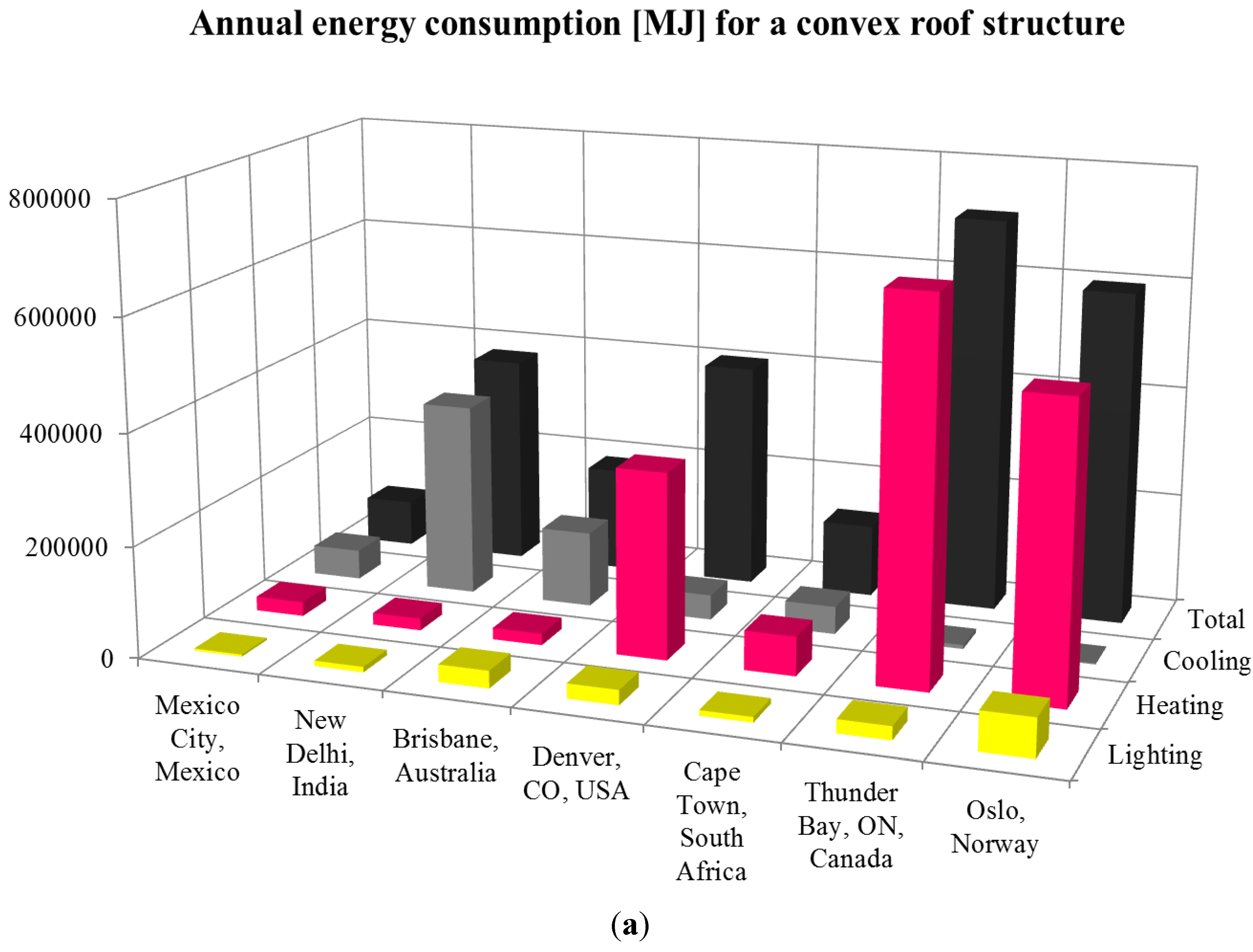
3.2. Simulation Results and Discussion

The results of the building energy consumption are presented graphically in Figure 4a convex, Figure 4b concave and Figure 4c flat and numerically in Table 2. In all scenarios the industrial plants with a north-light roof configuration (convex and concave) proved to yield superior (i.e., reduced) lighting energy consumption compared to a building with a flat roof and windows in the east and west walls. A typical difference range is 5%–25% between 30° N and 30° S, excluding latitudes very close to the Equator. The most pronounced difference is for Mexico City where a north-light roof configuration reduces the lighting energy consumption by 54% as compared to a flat roof with side windows. In the latter situation, the energy going into artificial lighting contributes more than 83% to the total annual building energy loads. Both convex and concave roof light systems maximize diffuse light in the interior of the single-volume building but avoid direct sunlight. To control the annual building energy consumption, the role and the interaction of the north-light configuration on the heating and cooling loads needs to be considered. Two scenarios arise.
Figure 4. (a) Annual building energy consumption for a plant with a convex roof and integrated north-lights; (b) Annual building energy consumption for a plant with a concave roof and integrated north-lights; (c) Annual building energy consumption for a plant with a flat roof and windows in walls.
Energies 06 01944 g004aEnergies 06 01944 g004b
Table 2. Numerical results for Annual Energy Consumption (MJ) for a convex, concave and flat roof.
CityConvex roofConcave roofFlat roof
LightingHeatingCoolingTotalLightingHeatingCoolingTotalLightingHeatingCoolingTotal
Mexico City3,72825,90753,73883,3733,86721,36757,14982,383147,6294,34226,991178,962
New Delhi9,68421,636348,336379,6569,98918,908337,630366,527138,0402,724239,394380,158
Brisbane31,27620,932135,881188,08931,74018,040134,266184,046124,1396,38397,739228,261
Denver26,672333,87945,103405,65426,831309,29344,332380,456188,303150,74256,856395,901
Cape Town9,67870,55750,069130,30410,13562,96850,652111,43987,44627,82334,137149,406
Thunder Bay24,246679,9067,158711,31024,659631,2727,418663,349161,397372,39811,868545,663
Oslo69,022527,4872,130598,63970,236487,4712,346560,053220,519277,2975,002502,818

3.2.1. Negative Effect of North-Light Roof on Building Energy Consumption

Instances of north-light roofs have been found as far north as Poland (52° N, 20° E). Although studies of north-light configurations in the Humid Continental zones like Thunder Bay and Oslo, generate lower lighting loads than the flat roof configuration. The extra interior air volume the north-light system entails, is responsible for the 2.1 times higher heating loads in the north-light systems. In both flat and curved configurations, the heating energy consumption is an order of magnitude larger than the lighting load and thus dominates the total energy consumption. Cooling needs in these regions are negligible.

3.2.2. Positive Effect of North-Light Roof on Building Energy Consumption

In New Delhi, Brisbane, Denver and Cape Town, both convex and concave skylight configurations show better lighting performance, but cause up to 182% higher heating (Denver and Mediterranean) or 48% higher cooling (New Delhi, Brisbane and Cape Town) loads due to the larger interior air volume. Figure 4 demonstrates that in these cases, heating and cooling loads do contribute large amounts to the total energy usage. In conclusion, for these zones, the total energy consumption for a plant with north-lights is slightly improved compared with a flat roof with wall windows. In Mexico City, the north-light configuration exhibits 62% improved lighting performance. The presented north-light configuration reduces the total energy consumption by 54%. This observation motivates the optimization framework presented in Section 4 that aims at further changing the roof shape to obtain minimum energy consumption while maintaining adequate interior environmental conditions

4. Optimization of Building Energy Consumption for a Plant with a North-Light Roof

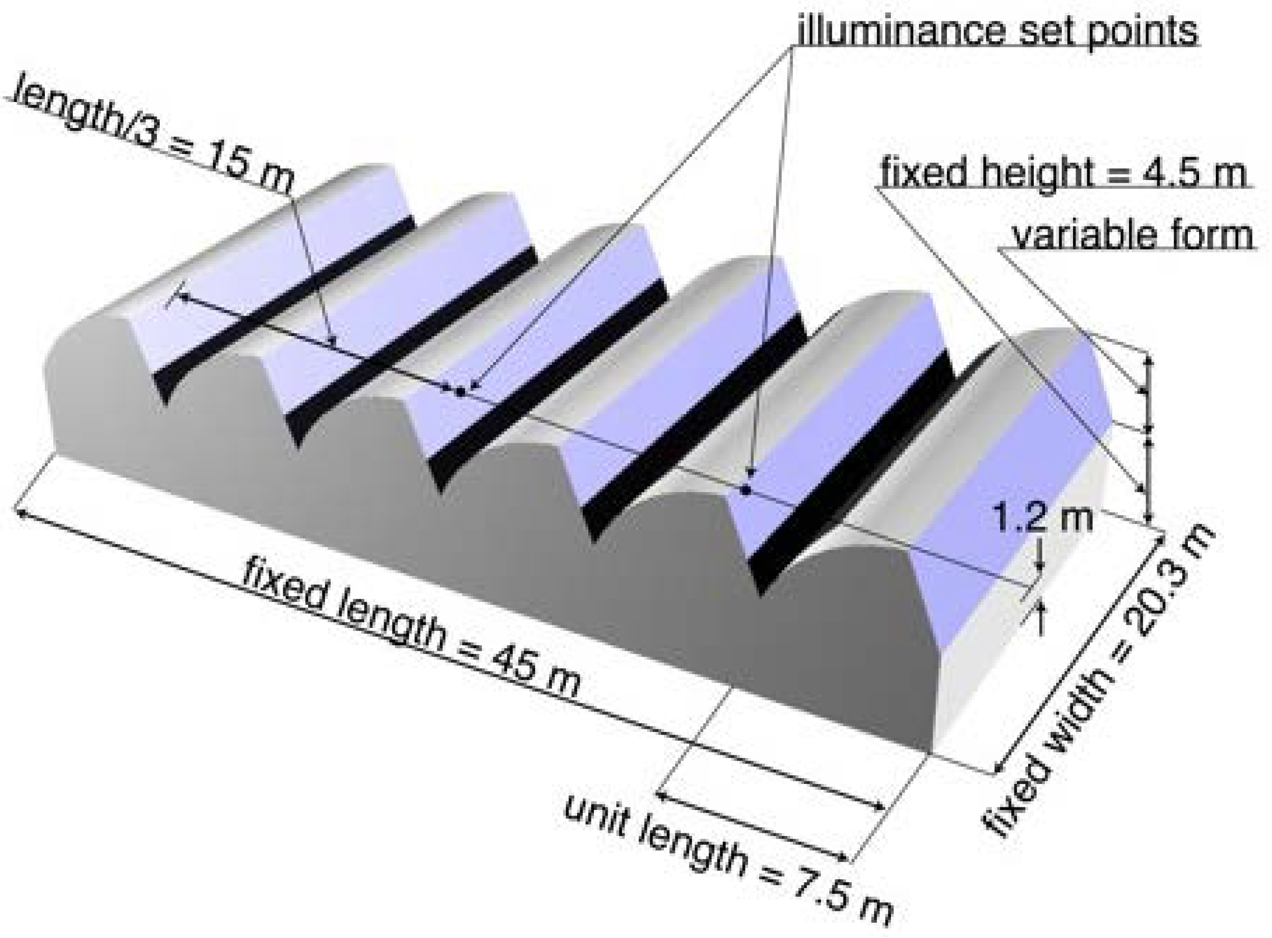
4.1. Problem Description

The optimization objective aims at finding building designs with north-lights integrated into the roof of a plant in order to achieve minimum building energy cost. For given production lines and processes, building designs with different north-light configuration will result in different building energy consumption. Figures 4a and b show that concave and convex roof shapes with north-lights will result in different lighting levels and levels of solar heat gain and hence different heating or cooling loads and different energy consumption of the HVAC system. Numerous factors can be controlled to minimize building energy consumption. The most fundamental parameters include: (i) building orientation and structure (size, partition, plan, etc.); (ii) wall/roof/floor construction (layers, thickness and materials); (iii) roof units (number, shape of opaque roof, construction in terms of layers, thickness, etc.); (iv) presence of natural ventilation and its control mode, etc. All these factors can be decision variables. The choice of these factors can also be heavily restricted the requirement for plant to be adaptable [17]. A plant has to change all or part of its use several times during the payback period. Minimal first cost will soon be negated by the expense of fitting new processes and working methods into an inherently unsuitable building. North-lights present themselves as suitable candidates for adaptable multi-strategy factories. The adaptability requirement fixes certain decision variables. First, to ensure adaptability, the single-story building is designed as a large open space, which is standardized and easily extended in two directions. Assuming a load bearing modular frame system, internal and external walls in the presented case studies can be demolished without compromising the building’s structural integrity. Second, its rectangular plan form with ratio of long to short sides between 1:1 and 3:1 minimizes internal travel distances where no particular traffic routes are dictated by a process. With its long to short side ratio of 2.2:1 the presented model falls within this category. Finally, the internal clear height is important, since the plant is difficult to modify once it has been built. For example, height is necessary for high stacking and overhead equipment. In the simulation models the height has been fixed at 4.5 m. The optimization problem arises from this problem description. The curved form of the north-light roof in Mexico City (discussed in Section 3.1.2.) is optimized to further reduce the building energy consumption. Mexico City was selected for the optimization process because its initial simulation results discussed in Section 3 indicated the best potential improvement in performance in comparison to the results for all the other cities selected.
The optimization design is based on a single volume one story building with six roof units containing integrated north-lights in Mexico City (19.4° N, 99.15° W). The building’s basic dimensions (length, width and height) are fixed and comply with adaptability for a multi-strategy factory design. As stated in Section 3.1., the building envelope has an overall length of 45 m (divided into six units), a width of 20.3 m and a clear wall height of 4.5 m as shown in Figure 3. The shape of the roof unit that holds the north-light can be described by three design parameters: ( α , a , h ) where α is the angle between the horizontal and the flat side of the roof, a is the absolute inclined height of the pitch of the roof and h is the absolute height of the arc relative to the chord as shown in Figure 5. When α > 0 and h = 0 , the roof form becomes planar and a saw-tooth configuration emerges. When α = 0 and h = 0 , the roof becomes a flat roof with skylights. In this situation the skylights might admit harsh direct overhead sunlight (and thus overheating) and glare. Figure 6 demonstrates how varying the values of the three design parameters ( α , a , h ) generates different shapes of the north-light roof.
Figure 5. Design Parameters in the north-light roof shape optimization.
Energies 06 01944 g005
Figure 6. For a set of fixed overall dimensions (length, height and width), different roof unit shapes with north-lights are generated by varying roof pitch, absolute roof height and radius of roof curvature. In figures a,b and c only the arc height h is varied, in figure d the angle α is also varied (a) convex: ( α , a , h ) = ( 67.83 ° , 4.319   m , 0.989   m ) ; (b) saw tooth: ( α , a , h ) = ( 67.83 ° , 4.319   m , 0   m ) ; (c) concave: ( α , a , h ) = ( 67.83 ° , 4.319   m , 0.989   m ) ; and (d) flat: ( α , a , h ) = ( 0 ° , 4.319   m , 0   m ) .
Energies 06 01944 g006

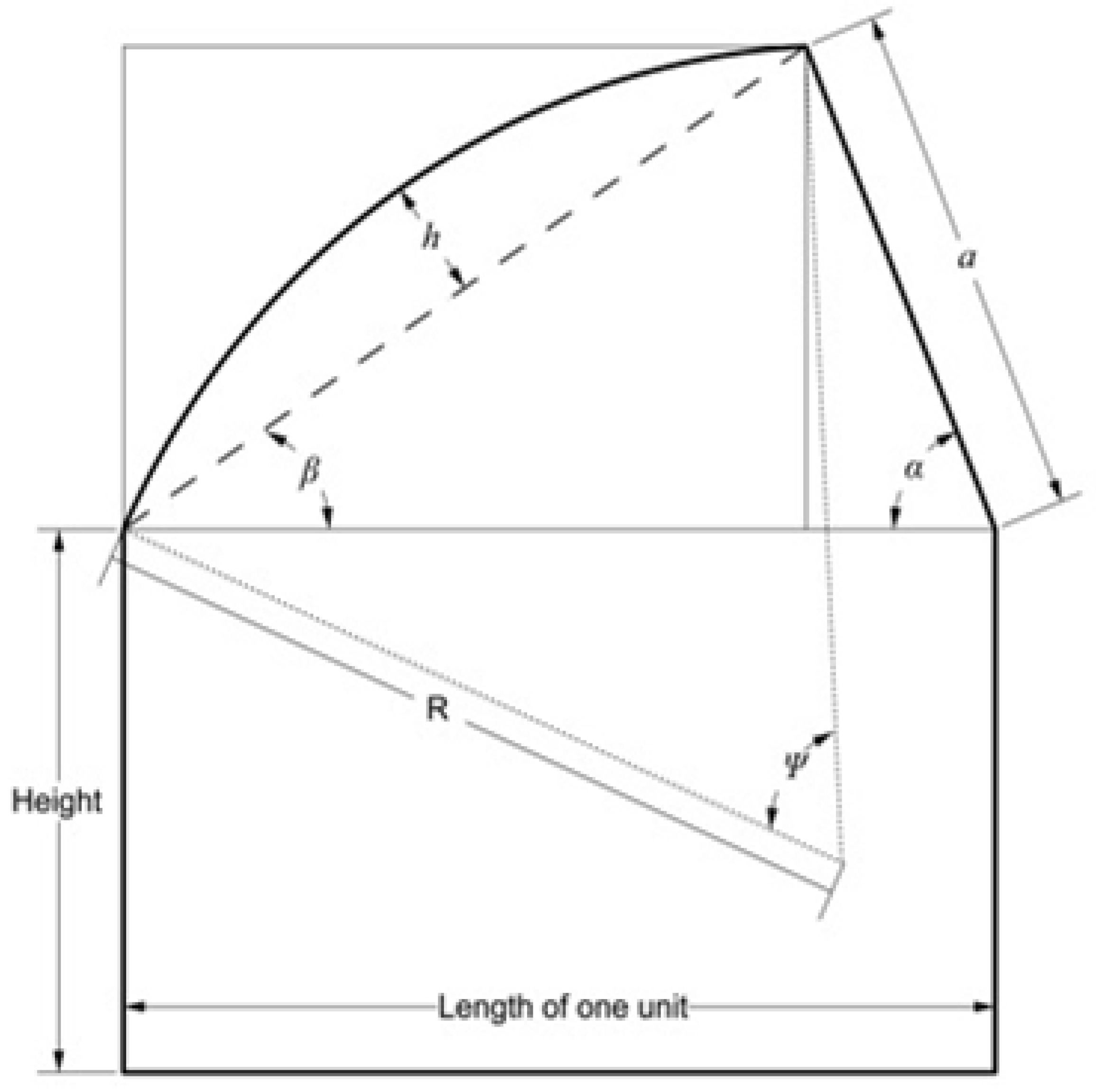
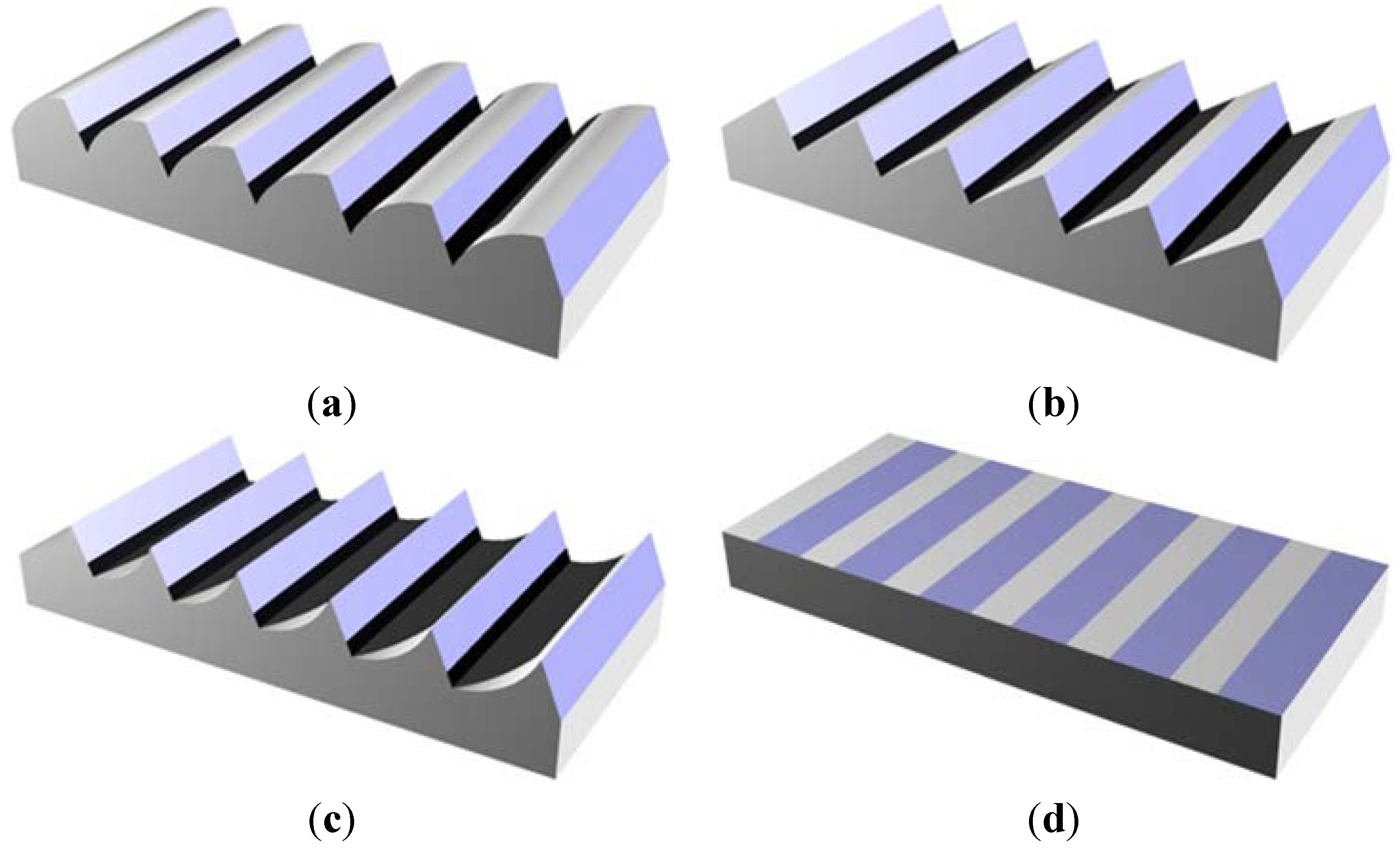
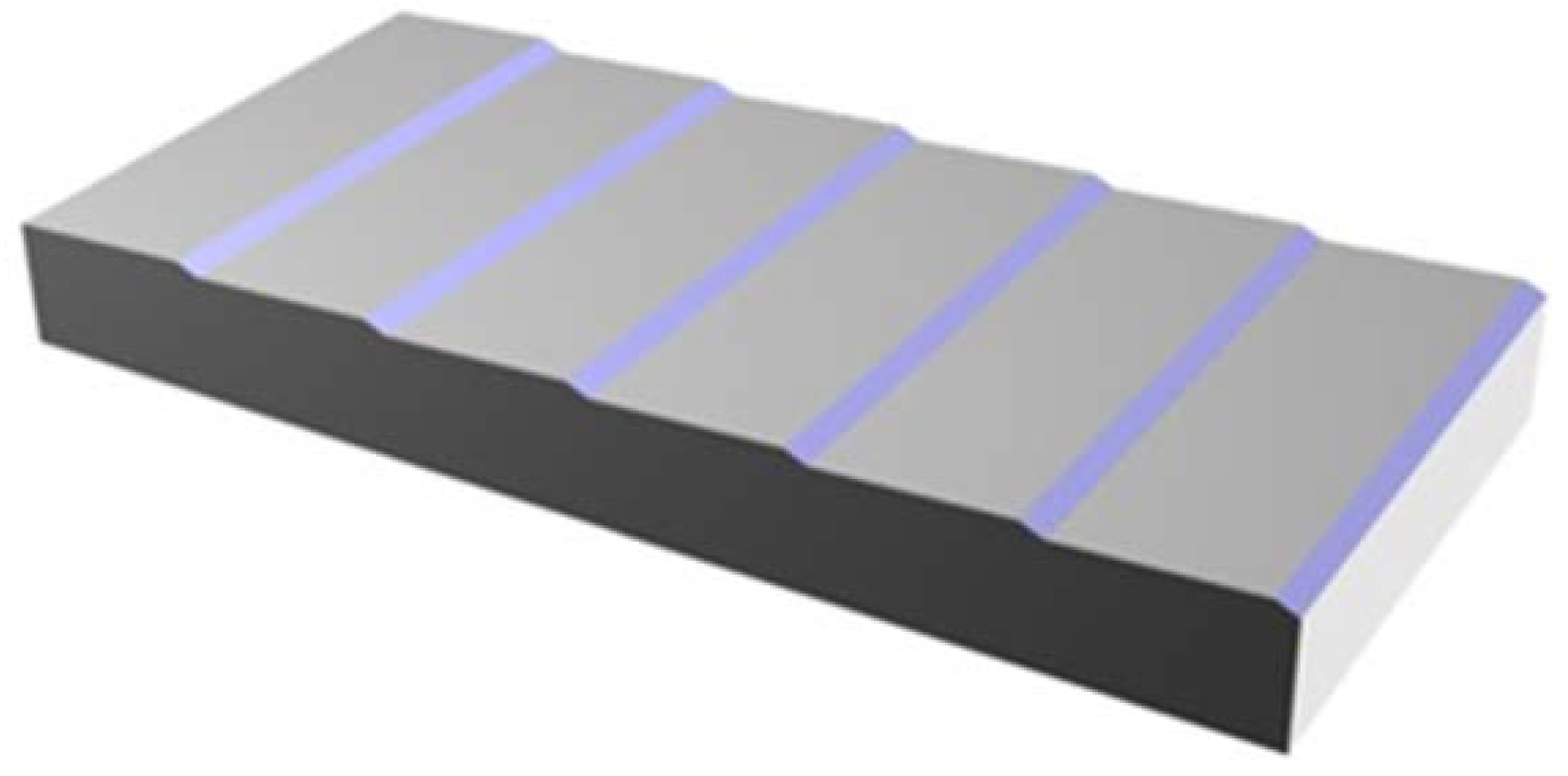
4.2. Roof Shape Optimization Problem

Figure 4 demonstrates that the interaction between different energy consuming systems turns developing an energy-efficient building design into a non-trivial problem. With the goal of minimizing the annual building energy consumption of this single-volume plant, this study optimizes the roof unit shape in terms of its control (or decision) variables. The other parameters are assumed to be fixed. The optimization problem can be formulated as follows:
The decision variables vector can be written as:
ϑ = ( α , a , h )
The constraints, which are geometric in nature, as: (Please check the style of the list)
  • 0 α π
  • a × cos ( α ) l
where l is the length of one unit.
For practical purposes, the vertical height of the roof unit should not exceed the wall height:
3.
a × sin ( α ) W a l l _ H e i g h t
Aesthetically the arc must be included in the rectangle enclosing the arc shown in Figure 5. Regardless of arc height h being positive or negative, this geometric constraint can be expressed as
4.
β ψ and β + ψ π 2
where β is the angle shown in Figure 6; and ψ is the center angle of the arc; Both β and ψ depend upon h.
The objective function can be written as:
Minimize  J = f ( ϑ )
where J, the objective value, is the building energy consumption necessary to maintain the interior environmental conditions (in terms of lighting level and dry-bulb temperature). This value is a function of the decision variables vector.

4.3. Roof Shape Problem Analysis

The building energy consumption analysis does not fit any analytical model. In other words, the objective function cannot be analytically defined. The objective value of any given feasible solution can only be obtained by simulation and thus a simulation-based optimization approach has to be applied [19]. This approach follows the following general framework: (i) a search of the design space with an appropriate search method to enumerate candidate plant designs; (ii) performance estimation of each candidate design using simulation; (iii) selection of a design (or a set of designs) as the solution (or solution set) with a specific selection rule. In the context of the roof shape optimization, this general framework poses two challenges. The first challenge lies in the fact that the feasible design set is continuous and infinite due to the continuity of the decision variables. With this design set, the optimal solution cannot be obtained by enumerating a finite number of times. On the other hand if an approximate optimal solution were desired, a large number of candidate designs would have to be explored. Generally, the closer one wants the solution to be to the absolute optimal solution, the more solutions have to be simulated. The second challenge lies in the computational time that the software EnergyPlus requires to obtain an accurate estimation of the building’s environmental performance. If simulations with a high level of confidence are required (e.g., using a more accurate computation algorithm or a smaller time step for the simulation), the computational burden (and thus the processing time) becomes heavy. The combination of these two challenges results in a “multiplication” effect that makes it difficult to find an approximate optimal solution within a limited timeframe due to the heavy total computational burden. To overcome this difficulty, the target of finding an approximate optimal solution is relaxed to finding an acceptable solution using the Ordinal Optimization (OO) method. In the current related studies, Genetic Algorithm is widely applied in finding optimal building design [20,21,22,23,24,25]. However, within limited simulation time, the GA-based approaches can hardly guarantee the quality of the design because only a small initial population or a small number of generations is allowed. Other algorithms like PSO encounter similar challenges [26]. In contrast, OO guarantees a high probability of finding satisfactory designs with limited computing.

4.4. Roof Shape Problem Solution

The OO method [27], first proposed for system optimization for discrete event dynamic systems, does not aim at finding the optimal solution for a given problem because in many situations on optimal solution is impossible or costs too much to obtain computationally. Instead the OO method guarantees finding acceptable designs with a high probability. The OO method has two basic characteristics that are beneficial to the roof shape optimization problem. First, this method can handle a large design search space. The number of design samples that need to be investigated using the OO method is independent of the problem. By uniformly sampling a number of plant designs (say 1000), the original search space is represented. No matter how many parameters are undetermined, the computational burden is equivalent as long as the simulation time for each design does not change significantly. Second, the method uses two simulation models. The first model is crude and efficient but has a low level of confidence. This model estimates the environmental performance of the sampled designs and identifies the most promising candidate designs. The second model more accurately simulates the performance of selected candidate designs and distinguishes acceptable solutions or one acceptable design. Using these two models, the OO method distributes the limited processing time and has a high probability of finding satisfactory solutions.
Following the OO procedure, the north-light roof shape optimization can be solved with the following four steps:
  • Step 1. Sampling: Randomly and uniformly sample N designs ( N = 1000 in this study);
  • Step 2. Simulate the sample’s environmental performance with the crude simulation model.
    • 2-1. For each of the N sample designs, simulate its building energy consumption using the crude model. The crude model is based on simulation in EnergyPlus using a time step of one hour, the maximum allowable time step.
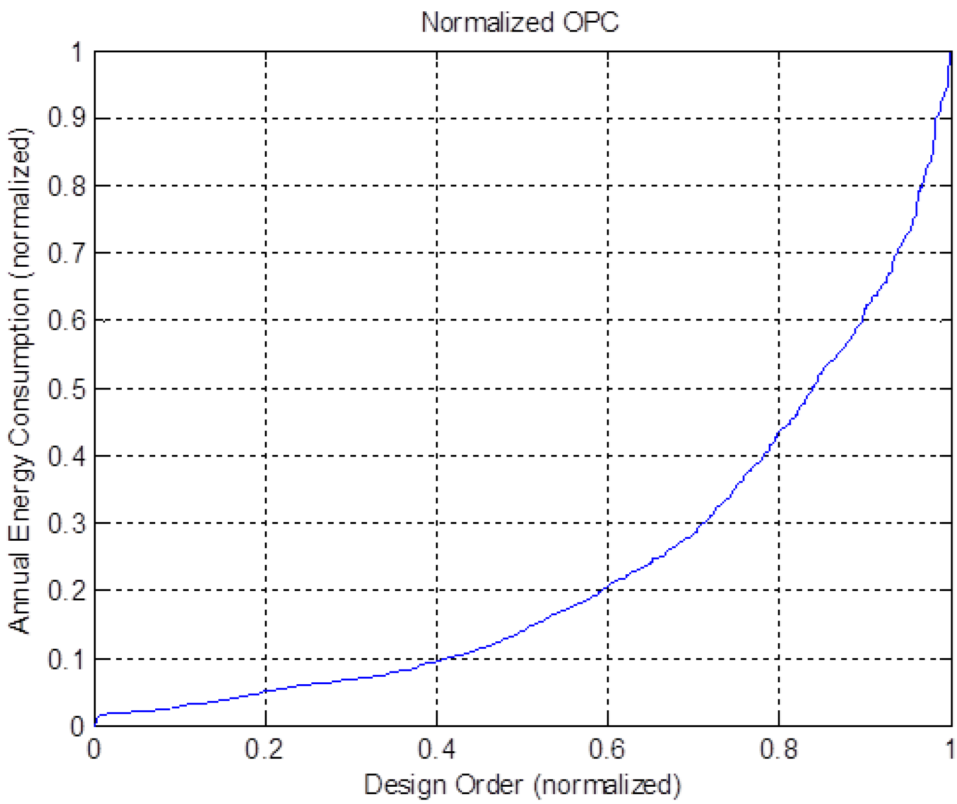
    • 2-2. Estimate the normalized Ordered Performance Curve (OPC) type based on the sorted performance of the N designs. OPC is defined in OO theory as a plot of performance values as a function of the order of performance.
  • Step 3. Design Selection: Order the estimated performance of the designs (from lowest to high building energy consumption) and select the top s designs as the selected set (horse racing selection rule). The variable s is determined according to the Universal Alignment Probability (UAP) table (defined in OO theory) and a desired acceptable level of k (also known as alignment level in OO theory, which is defined as the number of truly good enough designs in the selected set). A high noise level can be assumed since no prior knowledge is known about the noise.
  • Step 4. Further distinguish between the selected sample design performances and the more accurate simulation model.
    • 4-1. For each of the s selected designs, simulate the building energy consumption using the more accurate EnergyPlus model using a time step of one minute, the minimum allowable time step.
    • 4-2. Select the design with the best performance as the final solution.

4.5. Numerical Results for the Roof Shape Optimization

This section presents the numerically acceptable results of the roof shape optimization that achieves minimum building energy comsumption for a single-volume, one story building with six north-light roof units in Mexico City using the solution framework described in Section 4.3. The overall building dimensions, the envelope’s construction, and the performance criteria are kept identical to those described in Section 3.1. The simulations are run on a computer with 2.60 GHz CPU, 8 GB memory and a 64-bit operating system. Using the crude model, the simulation time for one design is about one minute. For the more accurate model, simulation time for one design is about 30 min. The total computational processing time is 1000 × 1 min + 46 × 30 min ≈ 40 h. In comparison, exploring the same 1000 candidate solutions using the more accurate model only, would require 1000 × 30 min = 21 days. The normalized OPC obtained in Step 2 is shown in Figure 7. The curve in this figure fits a “flat” type of OPC defined in OO theory. In other words, the curve’s rightmost segment is steep while the leftmost is flat. This fact shows that there are relatively many good designs (with low annual building energy consumption) and relatively few bad designs (with high annual building energy consumption) under the crude estimation. In Step 3, the number of designs is determined according to the OO theory such that the selected set contains at least one top 5% design with a probability of 0.95. This number is found to be 46. After further distinction in Step 4, the final solution obtained is with decision variables ( α , a , h ) = ( 24.98 ° , 0.887   m , 0.007   m ) . Figure 8 shows the single-volume building with the roof units with integrated north-lights that optimizes building energy consumption. This shape has an arc height approximately equal to 0, which nearly turns out to be a saw-tooth roof. This type of roof configuration can actually be found in the industrial areas around Mexico city as shown in Figure 9. When the industrial boom following the Mexican Revolution required the construction of factories, concrete hyperbolic paraboloid shells (also called umbrellas) filled the new industrial zones around Mexico City [28]. These shells were tilted to create a saw-tooth profile to let diffuse light enter the large open spaces while no specific consideration was given to heating and cooling.
The annual energy consumption of the building being studied (with optimized roof units) amounts to 3.5822 × 10¹⁰ J. In comparison, the non-optimized convex north-light roof investigated for Mexico City in Section 3.1.2., yielded an annual energy load of 8.3310 × 10¹⁰ J, or approximately 132% more. These numerical results demonstrate the inherent value of optimizing the north-light roof shape to achieve substantial improvements to annual building energy performance for specific climate zones.
Figure 7. Normalized OPC of the north-light roof shape optimization problem.
Energies 06 01944 g007
Figure 8. Optimized roof shape with integrated roof-light for a plant in Mexico City.
Energies 06 01944 g008
Figure 9. Factory in Mexico under construction with a tilted roof design similar to a saw-tooth profile to allow diffuse lighting into the interior space. (Photo courtesy of Candela Archive, Princeton University).
Energies 06 01944 g009

5. Conclusions

The north-light roof configuration has been used to bring diffuse lighting into factories since the end of the 18th century and throughout the Industrial Revolution, yet little research has focused on industrial design in comparison to research done on the energy consumption of office and residential buildings. Despite guidelines concerning thermal comfort, plant designers are not overly concerned with creating and maintaining a comfortable interior environment, with the exception of heating very cold spaces. Estimating the annual energy consumption for a previously established solution like the north-light plant can therefore help identify the contribution of the three key environmental loads (lighting, cooling and heating) to energy consumption and aid in finding an optimal solution for maintaining acceptable environmental conditions for workers while saving energy. This research is therefore highly relevant for multinationals aiming to improve the energy efficiency of their factories.
The comparative study of convex, concave and flat roofs for five different climate zones yields surprising conclusions. For an identical building, the lighting loads are always lower for a convex or concave roof configuration with north-lights than for a flat roof due to the ratio of glass to opaque areas . However, not in all cases is the total annual building energy consumption lower. The most surprising results are in the Humid Continental Zone (Thunder Bay and Oslo), where the north-light roof was first introduced, and where the total consumption is up to 31% higher for north-light variations. The increased interior air volume that the north-light configuration entails results in substantially higher heating loads, and thus cost, in these instances. Considering all factors (lighting, heating and cooling), the roof shape with north-lights positively influences the energy consumption in Mexico City with a 54% reduction. If the roof shape can be controlled, optimization is needed to achieve minimal energy consumption. Plant buildings vary from office and residential buildings in their scale (large single-volume). As a result, the environmental conditions have a larger inertia and consume relatively more energy to change or maintain environmental conditions. This fact also motivates the necessity of an optimization framework for the roof shape.
Accurate simulation of the building energy consumption can be computationally expensive, thus making the optimization time substantial. The use of a crude simulation model produces noise and will yield an unreliable solution. This paper introduces the OO method as a viable optimization framework for the presented energy optimization problem. This problem has a large search space and needs to be solved in a restricted computational time frame. The OO method guarantees satisfactory design solutions with a high probability while respecting processing time. In this study, two performance simulation models of different confidence levels are used. The optimization of the case study of the north-light roof shape for a plant design in Mexico city shows that another 132% in energy savings can be achieved by adopting the optimal roof shape.
Energy building consumption plays an increasingly important role in the total cost of manufacturing. Plant designers have traditionally adopted the north-light configuration without considering the total energy consumption picture. This paper clearly shows that this typology has tremendous energy-saving potential in specific climate zones. The presented roof shape optimization framework will significantly help identify energy reduction opportunities and provide assistance for energy efficient plant design.

Acknowledgments

Sigrid Adriaenssens and Mariam Wahed gratefully acknowledge the financial support of the Lewis Fund for Innovation in Energy and the Environment, administered through the Andlinger Center for Energy and the Environment of Princeton University. Qianchuan Zhao acknowledges additional financial support from NSFC (Nos. 61074034, 61021063). Hao Liu acknowledges additional financial support from Graduate School of Tsinghua University. Landolf Rhode-Barbarigos and Alex D. Jordan are acknowledged for their assistance in preparing the figures.

References

  1. Brei, M.; Johnson, K. Adapting Cities to Climate Change: Challenges for Urban Policy Innovation. Available online: http://www.feem.it/userfiles/attach/201252412465452012.05.24_Margaretha%20Breil_Katie%20Johnson_presentation.pdf (accessed on 19 December 2012).
  2. Markusen, J.R. Multinational firms, location and trade. World Econ. 1998, 21, 733–756. [Google Scholar] [CrossRef]
  3. Price, A.; Ross, M. Reducing industrial electricity costs—An automotive case study. Electr. J. 1989, 2, 40–51. [Google Scholar] [CrossRef]
  4. Leven, B.; Weber, C. Efficiency in Innovative Industries: Application and Benefits of Energy Indicators in the Automobile Industry. In Proceedings of American Council for an Energy-Efficient Economy: Summer Study on Energy Efficiency in Industry, Tarrytown, NY, USA, 24–27 July 2001.
  5. Liu, H.; Zhao, Q.; Cao, W.; Huang, N.; Zhao, X. Simulation Based Evaluation and Optimization for Energy Consumption of a Typical Welding Shop. In Proceedings of IEEE Conference on Automation Science and Engineering, Trieste, Italy, 24–27 August 2011.
  6. Galayda, J.; Yudelson, J. Inside Going Green: The little green book of corporate sustainability. 2009. Available online: http://www.naed.org/uploadedFiles/TEDGreenRoom/Resources/Glossary/Little_Green_Book_of_Corporate_Sustainability.pdf (accessed on 19 December 2012).
  7. Szokolay, S. Introduction to Architectural Science: The Basis of Sustainable Design; Elsevier: Oxford, UK, 2011. [Google Scholar]
  8. Paroncini, M.; Calcagni, B. Comment on “Daylighting performance of sawtooth roofs of industrial buildings”. Light. Res. Technol. 2003, 35, 358–359. [Google Scholar] [CrossRef]
  9. Lam, D.; Li, D. Measurements of solarradiation and illuminance on vertical surfaces and daylighting applications. Renew. Energy 2000, 20, 389–404. [Google Scholar] [CrossRef]
  10. Kuchta, M. Daylighting in American Industrial Architecture: Three Investigations. Master Thesis, Rice University, Houston, TX, USA, 1994. [Google Scholar]
  11. Joedicke, J. Shell Architecture; Karl Kramer: Stuttgart, Germany, 1963. [Google Scholar]
  12. Munce, J.F. Industrial Architecture: An Analysis of International Building Practice; F.W. Dodge Corporation: New York, NY, USA, 1960. [Google Scholar]
  13. Heras, M.; Jimenez, M.; San Isidro, M.; Zarzalejo, L.; Perez, M. Energetic analysis of a passive solar design, incorporated ina a courtyard after refurbishment, using an innovative cover component based on a sawtooth roof concept. Solar Energy 2005, 78, 85–96. [Google Scholar] [CrossRef]
  14. Asdrubali, F. Daylighting performance of sawtooth roofs of industrial buildings. Light. Res. Technol. 2003, 35, 343–359. [Google Scholar] [CrossRef]
  15. Tsangrassoulis, A.; Santamouris, M. A method to estimate the daylight efficiency of round skylights. Energy Build. 2000, 32, 41–45. [Google Scholar] [CrossRef]
  16. U.S. Department of Energy. EnergyPlus Energy Simulation Software. Available online: http://apps1.eere.energy.gov/buildings/energyplus/ (accessed on 19 December 2012).
  17. Drury, J. Metric Handbook; Architectural Press: Oxford, UK, 1999. [Google Scholar]
  18. U.S. Department of Energy. Policies for A/C and Heating Temperature Set-Points in Municipal Facilities. Available online: http://www.eereblogs.energy.gov/tap/post/QA-Policies-for-AC-and-Heating-Temperature-Set-points-in-Municipal-Facilities.aspx (accessed on 19 December 2012).
  19. Fu, M. Optimization for simulation: Theory versus practice. J. Comput. 2002, 14, 192–215. [Google Scholar]
  20. Wright, J.; Loosemore, H. The Multi-Criterion Optimization of Building Thermal Design and Control. In Proceedings of 17th International Building Performance Simulation Association Conference, Rio de Janeiro, Brazil, 13–15 August 2001.
  21. Wright, J.; Loosemore, H.; Farmani, R. Optimization of building thermal design and control by multi-criterion genetic algorithm. Energy Build. 2002, 34, 959–972. [Google Scholar] [CrossRef]
  22. Caldas, L.; Norford, L. Genetic algorithms for optimization of building envelopes and the design and control of HVAC systems. J. Solar Energy Eng. 2003, 125, 343–352. [Google Scholar] [CrossRef]
  23. Tuhus-Durow, D.; Krarti, M. Genetic algorithm based approach to optimize building envelope design for residential buildings. Build. Environ. 2010, 45, 1574–1584. [Google Scholar] [CrossRef]
  24. Wanga, W.; Zmeureanu, R.; Rivard, H. Applying multi-objective genetic algorithms in green building design optimization. Build. Environ. 2005, 40, 1512–1525. [Google Scholar] [CrossRef]
  25. Palonen, M.; Hasan, A.; Siren, K. A Genetic Algorithm for Optimzation of Building Envelope and HVAC System Parameters. In Proceedings of 11th International Building Performance Simulation Association Conference, Glasgow, Scotland, 27–30 July 2009.
  26. Wetter, M.; Wright, J. A comparison of deterministic and probalistic optimization algorithms for non smooth simulation-based optimization. Build. Environ. 2004, 39, 989–999. [Google Scholar] [CrossRef]
  27. Ho, Y.; Zhao, Q.; Jia, Q. Ordinal Optimization: Soft Optimization for Hard Problems; Springer: New York, NY, USA, 2007. [Google Scholar]
  28. Moyrera Garlock, M.; Billington, D. Felix Candela: Engineer, Builder, Structural Artist; Yale University Press: New Haven, CT, USA, 2008. [Google Scholar]

