Article

Research on an Axial Magnetic-Field-Modulated Brushless Double Rotor Machine

Department of Electrical Engineering, Harbin Institute of Technology, Harbin 150080, China
*
Author to whom correspondence should be addressed.
Energies 2013, 6(9), 4799-4829; https://doi.org/10.3390/en6094799
Submission received: 12 July 2013 / Revised: 1 September 2013 / Accepted: 3 September 2013 / Published: 12 September 2013
(This article belongs to the Special Issue Advances in Hybrid Vehicles)

Abstract

:
Double rotor machine, an electronic continuously variable transmission, has great potential in application of hybrid electric vehicles (HEVs), wind power and marine propulsion. In this paper, an axial magnetic-field-modulated brushless double rotor machine (MFM-BDRM), which can realize the speed decoupling between the shaft of the modulating ring rotor and that of the permanent magnet rotor is proposed. Without brushes and slip rings, the axial MFM-BDRM offers significant advantages such as excellent reliability and high efficiency. Since the number of pole pairs of the stator is not equal to that of the permanent magnet rotor, which differs from the traditional permanent magnet synchronous machine, the operating principle of the MFM-BDRM is deduced. The relations of corresponding speed and toque transmission are analytically discussed. The cogging toque characteristics, especially the order of the cogging torque are mathematically formulated. Matching principle of the number of pole pairs of the stator, that of the permanent magnet rotor and the number of ferromagnetic pole pieces is inferred since it affects MFM-BDRM’s performance greatly, especially in the respect of the cogging torque and electromagnetic torque ripple. The above analyses are assessed with the three-dimensional (3D) finite-element method (FEM).

1. Introduction

In recent years, double rotor machine has attracted great attention due to its wide application prospects in hybrid electric vehicles (HEVs) [1,2,3,4,5,6], wind power [7,8] and marine propulsion [9]. Consisting of a stator and two rotors, a double rotor machine can realize flexible energy transformation as an electronic continuously variable transmission. There have been several proposals for double rotor machines in the past, such as compound-structure permanent-magnetic synchronous machines (CS-PMSM) [10,11], induction machines based electrical variable transmission [12,13], switched reluctance double-rotor machines [14] and dual mechanical port machines [15]. Though these double rotor machines meet the demand of power-split characteristics, they have two major disadvantages. Firstly, the rotating windings need brushes and slip rings, which may cause problems such as maintenance and low reliability. Secondly, the inner-rotor winding is easily overheated [16,17]. To solve the above problems, a novel brushless double rotor permanent magnet machine based on the principle of magnetic-field modulation is presented in this paper. The axial magnetic-field-modulated brushless double rotor machine (MFM-BDRM) comprizes three parts: a stator, a modulating ring rotor and a permanent magnet rotor [18,19]. The modulating ring rotor, composed of evenly distributed ferromagnetic pole pieces and nonmagnetic pole pieces, is sandwiched between the stator and the permanent magnet rotor [20,21,22,23]. The brushless CS-PMSM system based on axial MFM-BDRM is a competitive alternative for HEV application, which is shown in Figure 1.
Figure 1. The axial-radial flux compound-structure permanent-magnetic synchronous machine (CS-PMSM) system.
Energies 06 04799 g001
The permanent magnet rotor is coupled to the shaft of the internal combustion engine (ICE) while the shaft of the modulating ring rotor, also as the revolving shaft of the permanent magnet synchronous machine, is linked to the final gear. By adjusting the frequency of stator winding current, the MFM-BDRM provides speed difference from the ICE to the load. The permanent magnet synchronous machine enables the torque decoupling from the ICE to the load.
The purpose of this paper is to propose an axial MFM-BDRM. As the number of pole pairs of the stator is not equal to that of the permanent magnet rotor, the useful harmonic fields modulated through the modulating ring rotor contribute to stable torque transmission [24,25,26,27,28]. The operating principle of the MFM-BDRM is deduced based on interaction of magnetic fields. To describe torque ripple characteristics, the cogging toque is mathematically formulated [29,30,31]. Matching principle of the number of pole pairs of the stator, that of the permanent magnet rotor, and the number of ferromagnetic pole pieces is discussed [32,33,34,35]. The above analyses are examined by three-dimensional (3D) finite-element method (FEM).

2. Theoretical Analysis

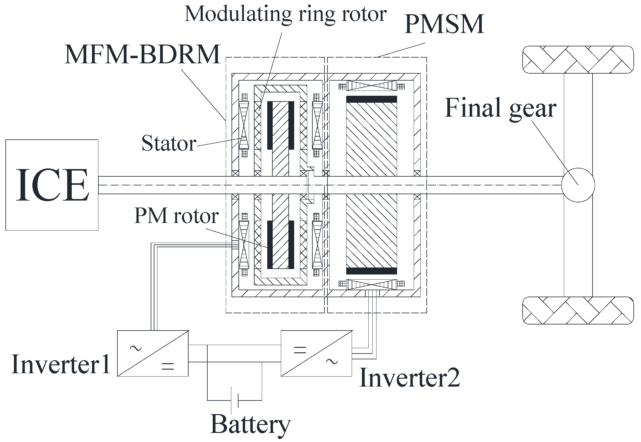
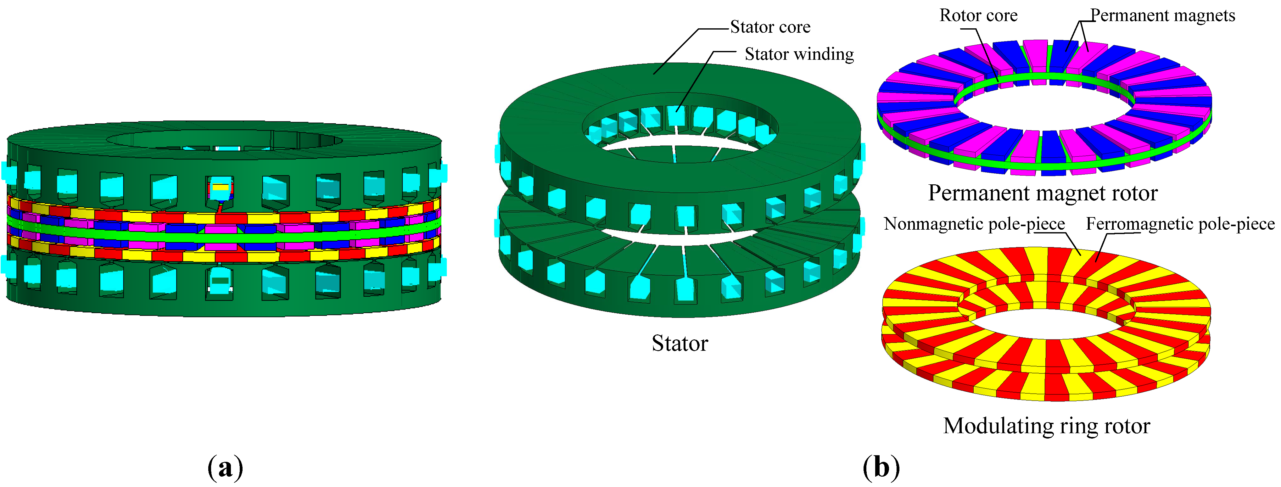
2.1. Principle of Operation

From the principle of electromechanical energy conversion, to realize stable electromagnetic torque transmission for traditional PMSM, it is required that the amplitude of magnetomotive force produced by the stator winding and that produced by the permanent magnet rotor be constant. Meanwhile, the angle between the above two magnetomotive forces should be constant as well. More specifically, there are two constraints to get constant electromagnetic torque: the number of pole pairs of the stator should be equal to that of the permanent magnet rotor, while the rotational speed of the stator magnetic field should also be equal to that of the permanent magnet rotor [36].
For the axial MFM-BDRM, the number of pole pairs of the permanent magnet rotor is not equal to that of the stator, which is different from traditional permanent magnet synchronous machine. To achieve stable torque transmission in the air gap adjacent to the permanent magnet rotor, the number of pole pairs of the permanent magnet rotor should be equal to that of some space harmonic magnetic field produced by the stator winding and modulated to this air gap through the modulating ring rotor, and the corresponding speeds should be synchronized. Meanwhile, to achieve stable torque transmission in the air gap adjacent to the stator, the number of pole pairs of the stator should be equal to that of some space harmonic magnetic field produced by the permanent magnet rotor and modulated to this air gap through the modulating ring rotor, and the corresponding speeds should be synchronized. In order to get comparatively large modulated space harmonic magnetic field, magnetic field distribution of the permanent magnet rotor and the stator winding are investigated separately. As torque transmission relies on the interaction of magnetic fields, the operation principle can be deduced based on magnetic field interaction. For simplification purposes, the permeabilities of the stator core, the permanent magnet rotor yoke and the ferromagnetic pole pieces are considered as infinite. Meanwhile, the flux leakage and the slotting effect are negligible.
First, the stator winding is not fed with current. The magnetomotive force produced by the permanent magnet rotor can be written by Equation (1):
F p ( z , θ , t ) = h = 1 , 3 , 5 ... f p h ( z ) cos [ h p p ( θ ω p t + θ 0 p ) ]
When the modulating ring rotor is removed, the flux density distribution in either air gap at an axial distance z produced by the permanent magnet rotor can be given in the following form by Equation (2):
B p ( z , θ , t ) = h = 1 , 3 , 5 ... b p h ( z ) cos [ h p p ( θ ω p t + θ 0 p ) ]
When the modulating ring rotor is taken into account, the distortion effect of the ferromagnetic pole pieces on the magnetic field is similar to the slotting effect in permanent magnet machine, which can be approximated by multiplying the original magnetic field distribution with a modulating function. Therefore, the flux density distribution in either air gap at an axial distance z produced by the permanent magnet rotor resulting from the existence of the modulating ring rotor can be expressed by Equation (3):
B p ( z , θ , t ) = { h = 1 , 3 , 5 ... b p h ( z ) cos [ h p p ( θ ω p t + θ 0 p ) ] } × { λ 0 ( z ) + j = 1 , 2 , 3 ... λ j ( z ) cos [ j p m ( θ ω m t + θ 0 m ) ] }               = h = 1 , 3 , 5 ... λ 0 ( z ) b p h ( z ) cos [ h p p ( θ ω p t + θ 0 p ) ]                 + h = 1 , 3 , ... j = 1 , 2 , 3 ... λ j ( z ) b p h ( z ) 2 cos [ ( h p p ± j p m ) ( θ h p p ω p ± j p m ω m h p p ± j p m t + h p p θ 0 p ± j p m θ 0 m h p p ± j p m ) ]
From Equation (3), the number of pole pairs in the space harmonic magnetic field distribution produced only by the permanent magnet rotor is given by Equation (4):
p p ( h , k ) = | h p p   +   k p m |      h = 1 ,   3 ,   5 ...        k = 0 ,   ± 1 ,   ± 2 ,   ± 3 ...
The corresponding rotational speed is given by Equation (5):
ω p ( h , k ) = h p p ω p + k p m ω m h p p + k p m
When k = 0, the number of pole pairs in the space harmonic magnetic field distribution and the corresponding rotational speed are shown in Equations (6) and (7):
p p ( h , 0 ) = h p p
ω p ( h , 0 ) = ω p
As such space harmonics have the same number of pole pairs and rotational speed with space harmonics before modulation, they are called the natural space harmonics.
When k ≠ 0, the number of pole pairs in the space harmonic magnetic field distribution and the corresponding rotational speed are shown in Equations (8) and (9):
p p ( h , k ) = | h p p + k p m |
ω p ( h , k ) = h p p ω p + k p m ω m h p p + k p m
It can be seen that such space harmonics result from modulation. Therefore they are called the modulated space harmonics.
From Equation (3), it can be seen that the amplitude of the modulated space harmonic depends on the bph(z) and λj(z). The combination h = 1, k = −1 possesses the comparatively large modulated space harmonic produced by the permanent magnet rotor in the air gap adjacent to the stator. To achieve stable torque transmission in the air gap adjacent to the stator, the pole-pair number of the comparatively large modulated space harmonic produced by the permanent magnet rotor pp(1, −1) (h = 1, k = −1) should be equal to that of the stator ps, which can be expressed by Equation (10):
| p p p m | = p s
The rotational speed of the comparatively large modulated space harmonic produced by the permanent magnet rotor ωp(1, −1) (h = 1, k = −1) should be equal to that of the stator magnetic field ωs, which can be expressed by Equation (11):
p m ω m p p ω p p m p p = ω s
Second, the stator adopts three-phase integral-slot distributed winding fed with alternating current (AC) while the permanent magnet rotor is not equipped with permanent magnets. The magnetomotive force produced by the stator winding can be written by Equation (12):
F s ( z , θ , t ) = F A ( z , θ , t ) + F B ( z , θ , t ) + F C ( z , θ , t )                 = v = 1 , 3 , 5 ... { f s v ( z ) cos [ v p s ( θ + θ 0 s ) ] cos ( p s ω s t )                   + v = 1 , 3 , 5 ... f s v ( z ) cos { v [ p s ( θ + θ 0 s ) 2 3 π ] } cos ( p s ω s t 2 3 π )                   + v = 1 , 3 , 5 ... f s v ( z ) cos { v [ p s ( θ + θ 0 s ) + 2 3 π ] } cos ( p s ω s t + 2 3 π )                = v = 1 , 7 , 13 , 19 ... 3 2 f s v ( z ) cos [ v p s ( θ ω s v t + θ 0 s ) ] + v = 5 , 11 , 17 ... 3 2 f s v ( z ) cos [ v p s ( θ + ω s v t + θ 0 s ) ]
When the modulating ring rotor is removed, the flux density distribution in either air gap at an axial distance z produced by the stator winding can be given in the following form by Equation (13):
B s ( z , θ , t ) = v = 1 , 7 , 13 , 19 ... b s v ( z ) cos [ v p s ( θ ω s v t + θ 0 s ) ] + v = 5 , 11 , 17 ... b s v ( z ) cos [ v p s ( θ + ω s v t + θ 0 s ) ]
When the modulating ring rotor is taken into account, the flux density distribution in either air gap at an axial distance z produced by the stator winding can be expressed by Equation (14):
B s ( z , θ , t ) = { v = 1 , 7 , 13 , 19 ... b s v ( z ) cos [ v p s ( θ ω s v t + θ 0 s ) ] + v = 5 , 11 , 17 ... b s v ( z ) cos [ v p s ( θ + ω s v t + θ 0 s ) ] } × { λ 0 ( z ) + j = 1 , 2 , 3 ... λ j ( z ) cos [ j p m ( θ ω m t + θ 0 m ) ] }              = v = 1 , 7 , 13 , 19 ... λ 0 ( z ) b s v ( z ) cos [ v p s ( θ ω s v t + θ 0 s ) ] + v = 5 , 11 , 17 ... λ 0 ( z ) b s v ( z ) cos [ v p s ( θ + ω s v t + θ 0 s ) ]                + v = 1 , 7 , 13 , 19 ... j = 1 , 2 , 3 ... λ j ( z ) b s v ( z ) 2 cos [ ( v p s + j p m ) ( θ p s ω s + j p m ω m v p s + j p m t + v p s θ 0 s + j p m θ 0 m v p s + j p m ) ]                + v = 1 , 7 , 13 , 19 ... j = 1 , 2 , 3 ... λ j ( z ) b s v ( z ) 2 cos [ ( v p s j p m ) ( θ p s ω s j p m ω m v p s j p m t + v p s θ 0 s j p m θ 0 m v p s j p m ) ]                + v = 5 , 11 , 17 ... j = 1 , 2 , 3 ... λ j ( z ) b s v ( z ) 2 cos [ ( v p s + j p m ) ( θ p s ω s + j p m ω m v p s + j p m t + v p s θ 0 s + j p m θ 0 m v p s + j p m ) ]                + v = 5 , 11 , 17 ... j = 1 , 2 , 3 ... λ j ( z ) b s v ( z ) 2 cos [ ( v p s j p m ) ( θ p s ω s j p m ω m v p s j p m t + v p s θ 0 s j p m θ 0 m v p s j p m ) ]
From Equation (14), the number of pole pairs in the space harmonic magnetic field distribution produced only by the stator winding is given by Equation (15):
p s ( v , l ) = | v p s + l p m |      v = 1 , 5 , 7 , 11 ...       l = 0 , ± 1 , ± 2 , ± 3 ...
The corresponding rotational speed is given by Equation (16):
ω s ( v , l ) = { p s ω s + l p m ω m v p s + l p m               when   v = 1 , 7 , 13 , 19 ... , l = 0 , ± 1 , ± 2 , ± 3 ... p s ω s + l p m ω m v p s + l p m             when   v = 5 , 11 , 17 ... , l = 0 , ± 1 , ± 2 , ± 3 ...
When l = 0, the number of pole pairs in the space harmonic magnetic field distribution and the corresponding rotational speed are shown in Equations (17) and (18):
p s ( v , 0 ) = v p s
ω s ( v , 0 ) = { ω s v                  when   v = 1 , 7 , 13 , 19 ... ω s v                when   v = 5 , 11 , 17 ...
As such space harmonics have the same number of pole pairs and rotational speed with space harmonics before modulation, they are called the natural space harmonics.
When l ≠ 0, the number of pole pairs in the magnetic field distribution and the corresponding rotational speed are shown in Equations (19) and (20):
p s ( v , l ) = | v p s + l p m |
ω s ( v , l ) = { p s ω s + l p m ω m v p s + l p m               when   v = 1 , 7 , 13 , 19 ... , l = 0 , ± 1 , ± 2 , ± 3 ... p s ω s + l p m ω m v p s + l p m             when   v = 5 , 11 , 17 ... , l = 0 , ± 1 , ± 2 , ± 3 ...
It can be seen that such space harmonics result from modulation. Therefore they are called the modulated space harmonics.
From Equation (14), it can be seen that the amplitude of the modulated space harmonic depends on the bsv(z) and λj(z). The combination v = 1, l = −1 possesses the comparatively large modulated space harmonic produced by the stator winding in the air gap adjacent to the permanent magnet rotor. To achieve stable torque transmission in the air gap adjacent to the permanent magnet rotor, the pole-pair number of the comparatively large modulated space harmonic produced by the stator winding ps(1, −1) (v = 1, l = −1) should be equal to the pole-pair number of the permanent magnet rotor pp, which can be expressed by Equation (21):
| p s p m | = p p
The rotational speed of the comparatively large modulated space harmonic produced by the stator winding ωs(1, −1) (v = 1, l = −1) should be equal to that of the permanent magnet rotor ωp, which can be expressed by Equation (22):
p m ω m p s ω s p m - p s     = ω p
From Equations (10) and (21), the relation of pp, ps and pm can be governed by Equation (23):
p s + p p = p m
From Equations (11), (22) and (23), the relation of ωp, ωs and ωm can be given by Equation (24):
ω p = p m ω m p s ω s p p
It can be found that the axial MFM-BDRM provides speed difference between the shaft of the modulating ring rotor and the shaft of the permanent magnet rotor by adjusting the frequency of stator winding current, which realizes the function of speed decoupling.

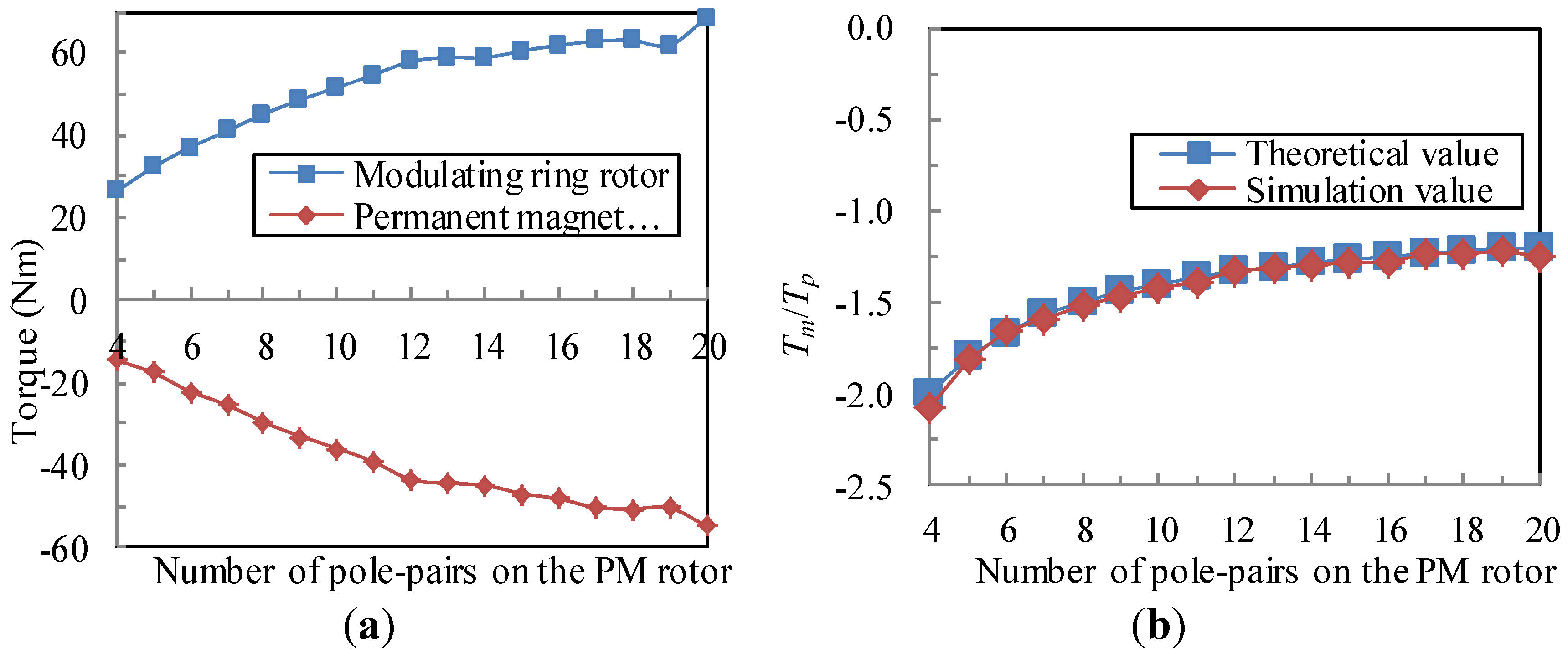
2.2. Torque Transmission

As mentioned in the operation principle, fundamental to the operation of the MFM-BDRM is the modulation of the magnetic fields produced by the permanent magnet rotor and the stator winding. Flux densities in either air gap are the sum of infinite harmonic terms. The space harmonic magnetic fields with the same pole-pair number and rotational speed interact with each other, contributing to constant electromagnetic torque.
Based on Equations (4), (5), (23) and (24), the number of pole pairs in the space harmonic magnetic field distribution produced only by the permanent magnet rotor and the corresponding rotational speed can be expressed by Equations (25) and (26):
p p ( h , k ) = | h p p + k p m | = | h ( p m p s )+ k p m |           = | h p s ( h + k ) p m |
ω p ( h , k ) = h p p ω p + k p m ω m h p p + k p m = h ( p m p s ) × p m ω m p s ω s ( p m p s ) + k p m ω m h ( p m p s ) + k p m           = h p s ω s ( h + k ) p m ω m h p s ( h + k ) p m
By considering Equations (15), (16), (25) and (26), it can be deduced that pp(h, k) equals ps(v, l) and ωp(h, k) equals ωs(v, l) when the combination of h, k, v and l is determined by Equation (27):
h = v = 1      k + l = 1
It demonstrates that the satisfied space harmonics produced by the permanent magnet rotor and the stator winding have the same pole-pair number and rotational speed, which can contribute to the average torque. The space harmonics governed by Equation (27) are called effective harmonics.
According to Newton’s third law, Equation (28) shows torque equilibrium relation of three parts:
T m = ( T s + T p )
The energy conservation relation between input power and output power is given by Equation (29):
T m ω m + T S ω S + T P ω P = 0
Therefore, the torque ratio between output torque and input torque is given by Equation (30):
T m T p = P m P p
It can be seen that the choice of the combination between the number of pole pairs of the permanent magnet rotor and the number of ferromagnetic pole pieces determines the torque transmission capability. With a certain combination between the number of pole pairs of the permanent magnet rotor and the number of ferromagnetic pole pieces, the torque ratio is confirmed, which explains that the axial MFM-BDRM can only transfer torque by a torque ratio rather than realize torque control.

2.3. Torque Ripple

Torque ripple of the axial MFM-BDRM is composed of the cogging torque and the electromagnetic torque ripple. When the stator winding is not fed with current, torque ripple is caused by the interaction between the permanent magnet rotor and the ferromagnetic pole pieces of the modulating ring rotor, i.e., the cogging torque. Under the load condition, when the space harmonics produced by the permanent magnet rotor have the same pole-pair number but different rotational speeds with the space harmonics produced by the stator winding, the electromagnetic torque ripple which results on two rotors arises.

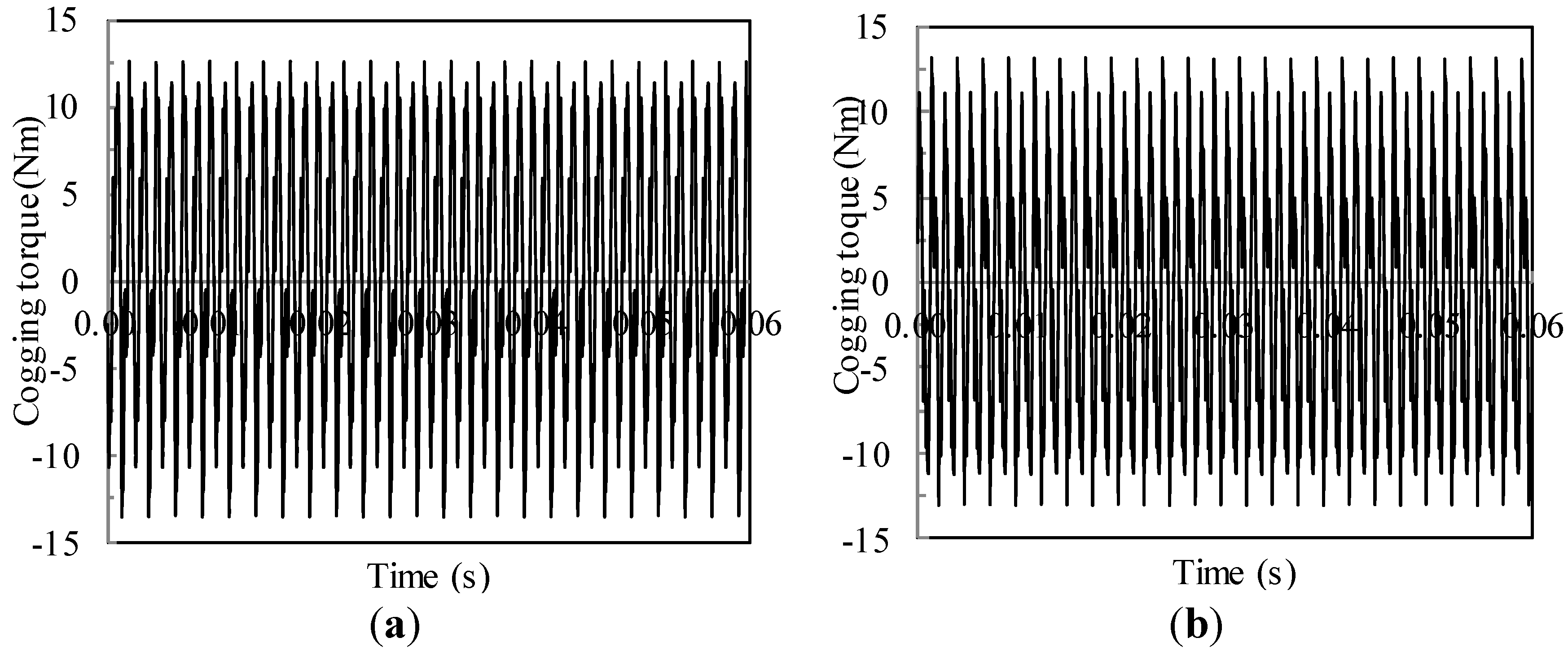
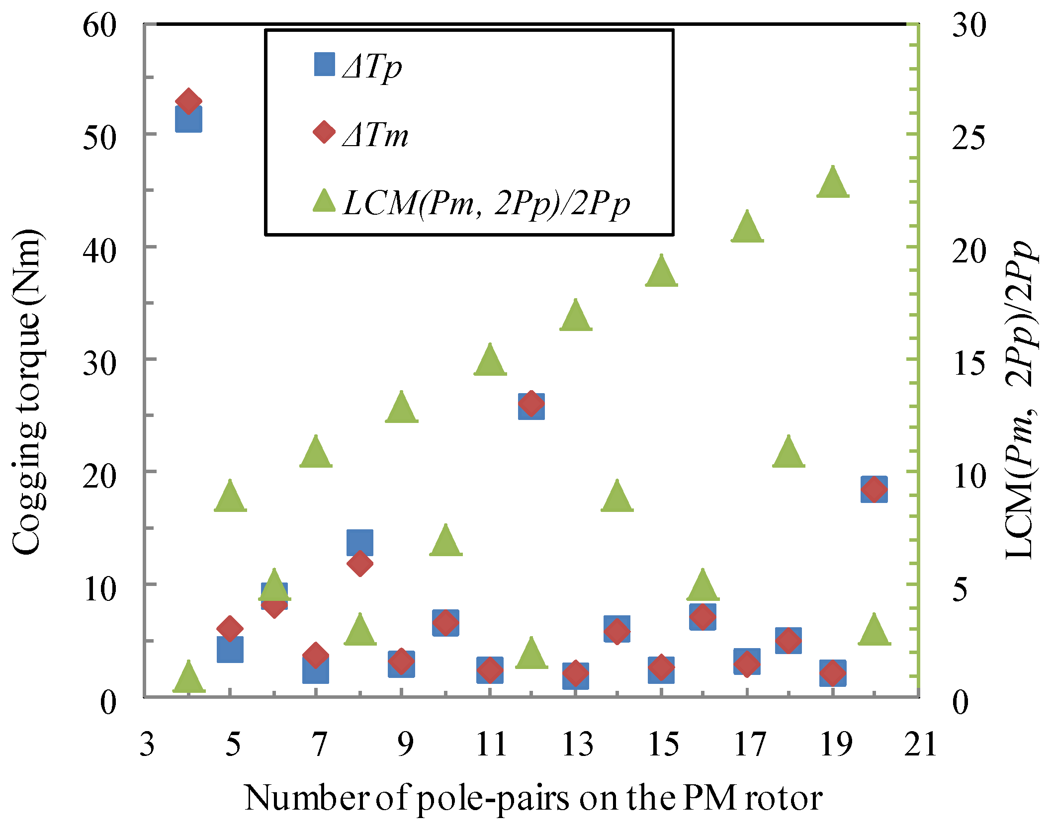
2.3.1. Cogging Torque

The cogging torque of interaction between the permanent magnet rotor and the ferromagnetic pole pieces of the modulating ring rotor is mathematically formulated. It should be stressed that the purpose of analysis below is the law of the cogging torque rather than accurate calculation.
When there is no current flow i in the stator coil, the cogging torque can be calculated from differentiating the total magnetic energy W with respect to the relative position angle α by Equation (31):
T c o g = W α | i = 0
Assuming that the magnetic energy is only stored in the air gap where the magnetic resistance is high, W can be expressed by Equation (32):
W = 1 2 μ 0 V B 2 d V
For simplicity, initial phase angles of the permanent magnet rotor and the modulating ring rotor are set θ0p = 0 and θ0m = 0, respectively. The flux density due to the permanent magnet rotor in the air gap adjacent to the permanent magnet rotor is regarded as even distribution along z axis. When two rotors rotate at different speeds, the relation between Δθp and Δθm can be governed by Equations (33) and (34):
Δ θ p Δ θ m = ω p ω m
Δ θ m Δ θ p = α
Therefore, Δθp and Δθm can be obtained in Equations (35) and (36):
Δ θ p = ω p ω m ω p α
Δ θ m = ω m ω m ω p α
Equation (2) can be written in the following form by Equation (37):
B p ( θ , α ) = h = 1 , 3 , 5 ... b p h cos [ h p p ( θ ω p ω m ω p α ) ]
The modulation function can be expressed by Equation (38):
λ ( θ , α ) = λ 0 + j = 1 , 2 , 3 ... λ j cos [ j p m ( θ ω m ω m ω p α ) ]
For the axial MFM-BDRM, Equation (32) can be expanded to Equation (39):
W = ( R o 2 R i 2 ) δ 4 μ 0 0 2 π B p 2 ( θ , α ) λ 2 ( θ , α ) d θ
B p 2 ( θ , α ) and λ 2 ( θ , α ) are expanded to Equations (40) and (41) by applying the Fourier series expansions to the integral part of Equation (39):
B p 2 ( θ , α ) = B 0 + h = 1 , 3 , 5 ... B h cos [ 2 h p p ( θ ω p ω m ω p α ) ]
λ 2 ( θ , α ) = G 0 + j = 1 , 2 , 3 ... G j cos [ j p m ( θ ω m ω m ω p α ) ]
The integral part of Equation (39) can be expanded to Equation (42):
B p 2 ( θ , α ) λ 2 ( θ , α ) = B 0 G 0 + j = 1 , 2 , 3 ... B 0 G j cos [ j p m ( θ ω m ω m ω p α ) ] + h = 1 , 3 , 5 ... G 0 B h cos [ 2 h p p ( θ ω p ω m ω p α ) ]    + h = 1 , 3 , 5 ... j = 1 , 2 , 3 ... B h G j 2 cos [ ( 2 h p p + j p m ) θ 2 h p p ω p + j p m ω m ω m ω p α ]    + h = 1 , 3 , 5 ... j = 1 , 2 , 3 ... B h G j 2 cos [ ( 2 h p p j p m ) θ 2 h p p ω p j p m ω m ω m ω p α ]
The first term of Equation (42) becomes zero by partial derivation of α. The second, third and fourth terms become zero by integration over one period. Therefore, the condition for the existence of the cogging torque is the coefficient of θ in the fifth term zero, as shown by Equation (43).
2 h p p = j p m
The cogging torque is presented in Equation (44):
T c o g = π δ p m 4 μ 0 ( R o 2 R i 2 ) j = 1 , 2 , 3 ... j G j B j p m 2 p p sin ( j p m α )
From Equations (43) and (44), it can be seen that the fundamental order of the cogging torque is the least common multiple between pm and 2pp. It means that when the rotation angles of two rotors differ by 2π, viz. t = 60 ω m ω p , the number of torque ripple on two rotors is LCM (pm, 2pp).
The amplitude of the cogging torque mainly depends on B L C M ( p m , 2 p p ) 2 p p . Thus, the larger the least common multiple between pm and 2pp, and the lower the number of poles on the permanent magnet rotor, the smaller the amplitude of the cogging torque will be.
When two rotors rotate at different speeds, if the permanent magnet rotor rotates c permanent magnet pole pieces while the modulating ring rotor rotates d ferromagnetic pole pieces, cogging torque waveform will repeat the foregoing waveform. The relation between Δθp and Δθm can be expressed by Equations (45) and (46):
Δ θ p = ω p ω m ω p α = c π p p         c = 1 , 2 , 3 ...
Δ θ m = ω m ω m ω p α = d p m         d = 1 , 2 , 3 ...
From Equations (45) and (46), the relation between c and d can be obtained in Equation (47):
c d = 2 p p ω p p m ω m
Therefore, the smallest integers cmin and dmin that satisfy the condition of Equation (47) can be achieved. The period of cogging torque waveform tcog is determined by Equation (48):
t c o g = c min 30 p p ω p
where the unit of ωp is revolutions per minute, i.e., rpm.

2.3.2. Electromagnetic Torque Ripple

From the principle of electromechanical energy conversion, it can be seen that when the number of pole pairs of the stator equals that of the permanent rotor, but the rotational speed of the stator magnetic field is not equal to that of the permanent rotor, electromagnetic torque ripple will be obtained [36].
For the axial MFM-BDRM, the harmonic fields with the same pole-pair number but different rotational speeds interact with each other, resulting in electromagnetic torque ripple. With the existence of the modulating ring rotor, there are amount of space harmonic magnetic fields in either air gap. Therefore, combination between the number of pole pairs of the permanent magnet rotor and that of the stator has a significant influence on the electromagnetic torque ripple. Since the stator adopts three-phase integral-slot distributed winding in this paper, the number of pole pairs of the stator should be small. If the number of pole pairs of the stator is large, the slot number of the stator will be large as well, resulting in super thin tooth breadth of the inner diameter of the stator. Circumstances of the significant electromagnetic torque ripple are investigated under the premise that the number of pole pairs of the stator is no bigger than that of permanent magnet rotor.
When the number of pole pairs of the permanent magnet rotor is an integral multiple of that of the stator, pp and pp(1, 1) can be expressed by Equations (49) and (50):
p p = e p s
p p ( 1 , 1 ) = ( 2 e + 1 ) p s
where e is a positive integer.
The first circumstance is e = 3g (g = 1, 2, 3…), in which pp(1, 1) can be expressed by Equation (51):
p p ( 1 , 1 ) = ( 6 g + 1 ) p s = p s ( 6 g + 1 , 0 )
In this case, the modulated space harmonic with the number of pole pairs pp(1, 1) produced by the permanent magnet rotor is the major harmonic with the rotational speed p p ω p + p m ω m p p + p m while the space harmonic with the number of pole pairs ps(6g+1, 0) produced by the stator winding is the natural space harmonic with the rotational speed ω s 6 g + 1 . Since the two space harmonics have the same pole-pair number but different rotational speeds, their interaction will contribute to electromagnetic torque ripple in either air gap under the load operation. As the modulated space harmonic with the pole-pair number pp(1, 1) has large amplitude, significant electromagnetic torque ripple arises. It should be notable that the smaller e or g is, the larger amplitude of the natural space harmonic with the number of pole pairs ps(6g+1, 0) will be, which results in higher electromagnetic torque ripple.
The second circumstance is e = 3g − 1 (g = 1, 3, 5…), in which pp(1, 1) can be expressed by Equation (52):
p p ( 1 , 1 ) = ( 6 g 1 ) p s = p s ( 6 g 1 , 0 )
In this case, the modulated space harmonic with the number of pole pairs pp(1, 1) produced by the permanent magnet rotor is the major harmonic with the rotational speed p p ω p + p m ω m p p + p m while the space harmonic with the number of pole pairs ps(6g−1, 0) produced by the stator winding is the natural space harmonic with the rotational speed ω s 6 g 1 . Their interaction will contribute to electromagnetic torque ripple in either air gap under the load operation. As the modulated space harmonic with the pole-pair number pp(1, 1) has large amplitude, significant electromagnetic torque ripple arises. It should be notable that the smaller e or g is, the larger amplitude of the natural space harmonic with the number of pole pairs ps(6g−1, 0) will be, which results in higher electromagnetic torque ripple.
The third circumstance is e = 3g − 1 (g = 2, 4, 6…), in which pp and pp(1, 1) can be expressed by Equations (53) and (54):
p p = ( 3 g 1 ) p s = p s ( 3 g 1 , 0 )
p p ( 1 , 1 ) = ( 6 g 1 ) p s = p s ( 6 g 1 , 0 )
In this case, the modulated space harmonic with the number of pole pairs pp(1, 1) produced by the permanent magnet rotor is the major harmonic with the rotational speed p p ω p + p m ω m p p + p m while the space harmonic with the number of pole pairs ps(6g−1, 0) produced by the stator winding is the natural space harmonic with the rotational speed ω s 6 g 1 . Moreover, the natural space harmonic with the number of pole pairs pp produced by the permanent magnet rotor is the fundamental harmonic with the rotational speed ωp while the space harmonic with the number of pole pairs pp(3g−1, 0) produced by the stator winding is the natural space harmonic with the rotational speed ω s 3 g 1 . Therefore, two kinds of non-ignorable harmonic interactions will contribute to electromagnetic torque ripple. As the modulated space harmonic with the pole-pair number pp(1, 1) and the fundamental harmonic with the pole-pair number pp both have large amplitudes, significant electromagnetic torque ripple arises. It should be notable that the smaller e or g is, the larger amplitudes of the natural space harmonics with the number of pole pairs ps(6g−1, 0) and ps(3g−1, 0) will be, which results in higher electromagnetic torque ripple.
The fourth circumstance is e = 3g + 1 (g = 0, 2, 4…), in which pp(1, 1) can be expressed by Equation (55):
p p = ( 3 g + 1 ) p s = p s ( 3 g + 1 , 0 )
In this case, the natural space harmonic with the number of pole pairs pp produced by the permanent magnet rotor is the fundamental harmonic with the rotational speed ωp while the space harmonic with the number of pole pairs ps(3g+1, 0) produced by the stator winding is the natural space harmonic with the rotational speed ω s 3 g + 1 . Their interaction will contribute to electromagnetic torque ripple in either air gap under the load operation. As the natural space harmonic with the pole-pair number pp(1, 1) has large amplitude, significant electromagnetic torque ripple arises. It should be notable that the smaller e or g is, the larger amplitude of the natural space harmonic with the number of pole pairs ps(3g+1, 0) will be, which results in higher electromagnetic torque ripple.
The last circumstance is e = 3g + 1 (g = 1, 3, 5…). In this case, no dominant harmonic interaction will contribute to electromagnetic torque ripple. It should be notable that space harmonics contributing to electromagnetic torque ripple also exist. Their interaction will result in less significant electromagnetic torque ripple.
When the number of pole pairs of the permanent magnet rotor is not an integral multiple of that of the stator, no dominant harmonic interaction will contribute to electromagnetic torque ripple. It should be notable that space harmonics contributing to electromagnetic torque ripple also exist. Their interaction will result in less significant electromagnetic torque ripple.
With no doubt, the existence of torque ripple will be detrimental to the performance of the axial MFM-BDRM. From analysis of the cogging torque and electromagnetic torque ripple above, it can be seen that the adoption of the case that the greatest common divisor between the pole-pair number on the permanent magnet rotor and the pole-pair number on the stator is 1 can greatly reduce torque ripple, thus significantly improve the performance of the machine.

3. FEM Simulation

By using 3D time-stepping FEM, validity of the above theoretical analyses is assessed [37]. With the number of pole pairs of the stator being 4, the number of pole pairs of the permanent magnet rotor being 17 and the number of ferromagnetic pole pieces being 21, 3D simulation model of the axial MFM-BDRM is shown in Figure 2.
Figure 2. Three-dimensional (3D) simulation model of the axial magnetic-field-modulated brushless double rotor machine (MFM-BDRM): (a) overall view; and (b) exploded view.
Energies 06 04799 g002
The permanent magnet rotor is equipped with sintered NdFeB permanent magnets. Silicon steel laminations are employed for the ferromagnetic pole pieces and the stator.

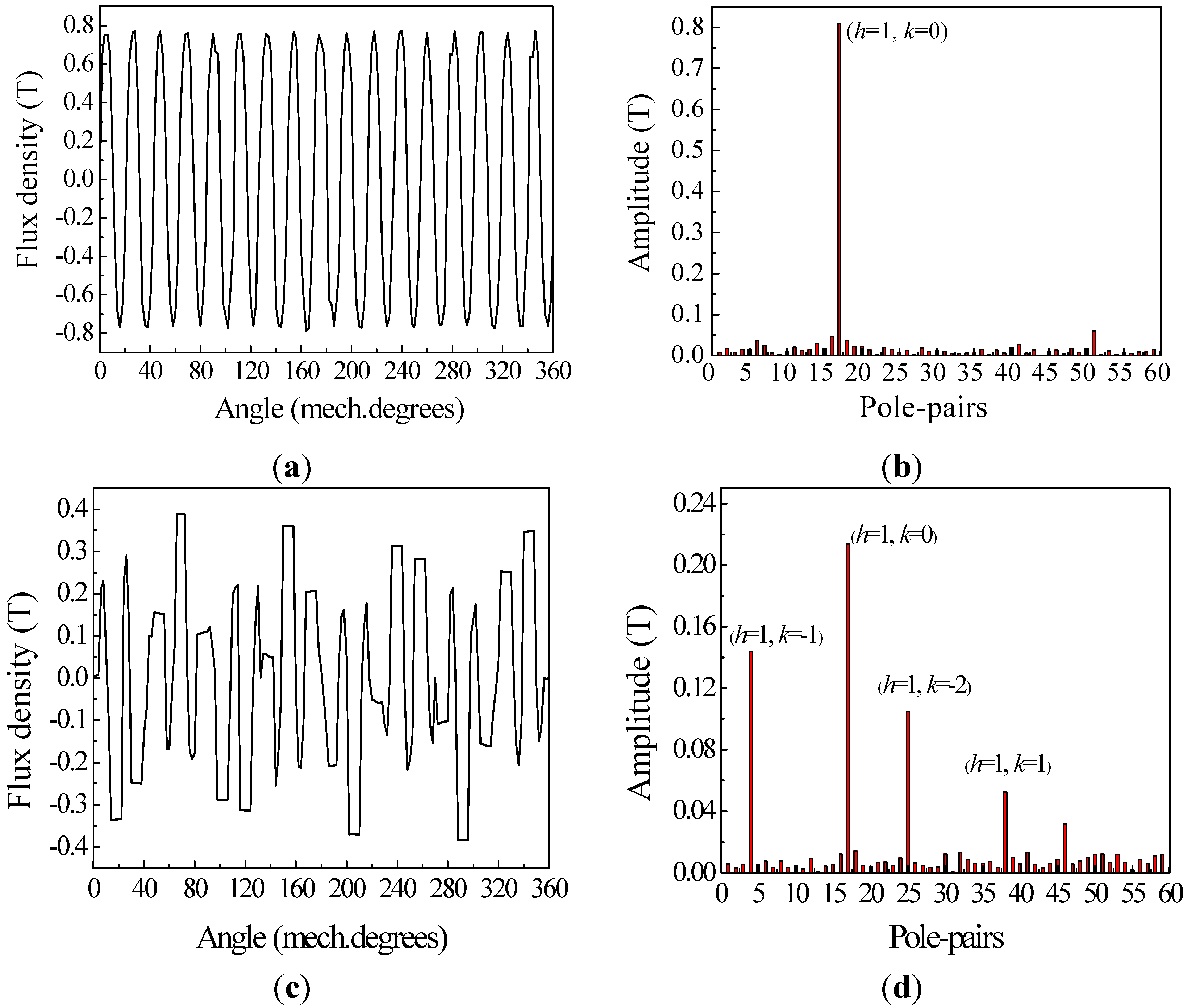
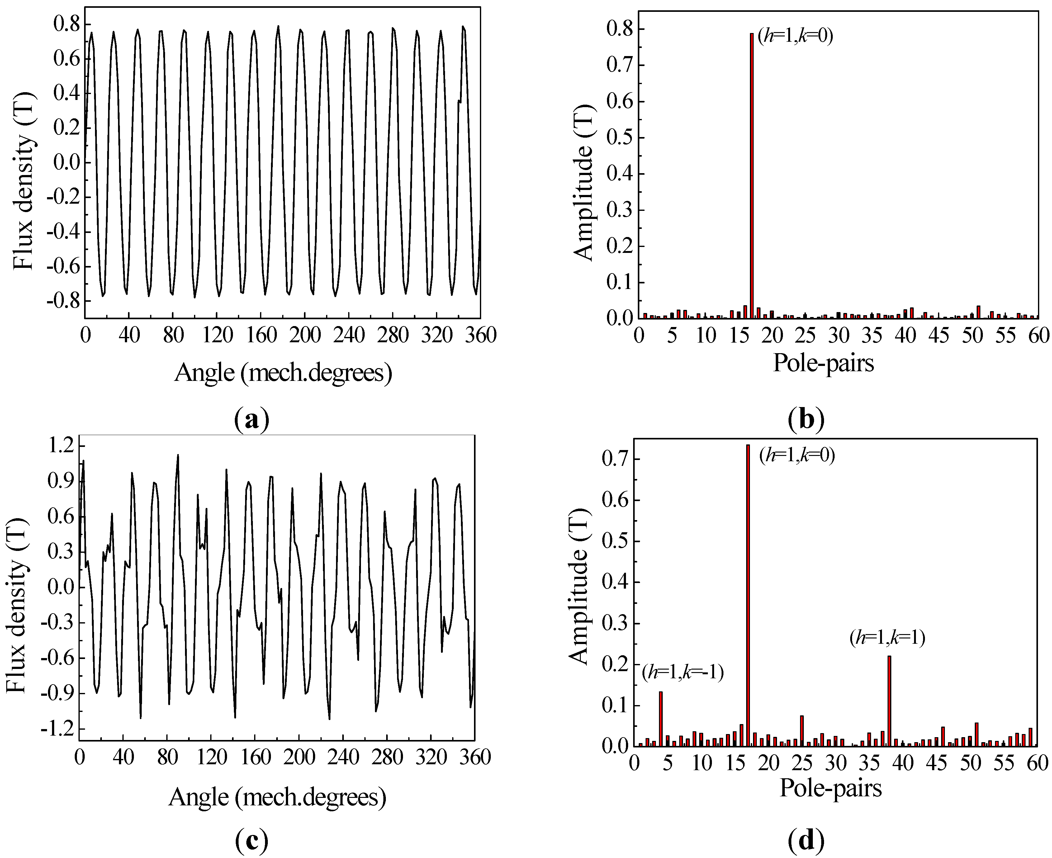
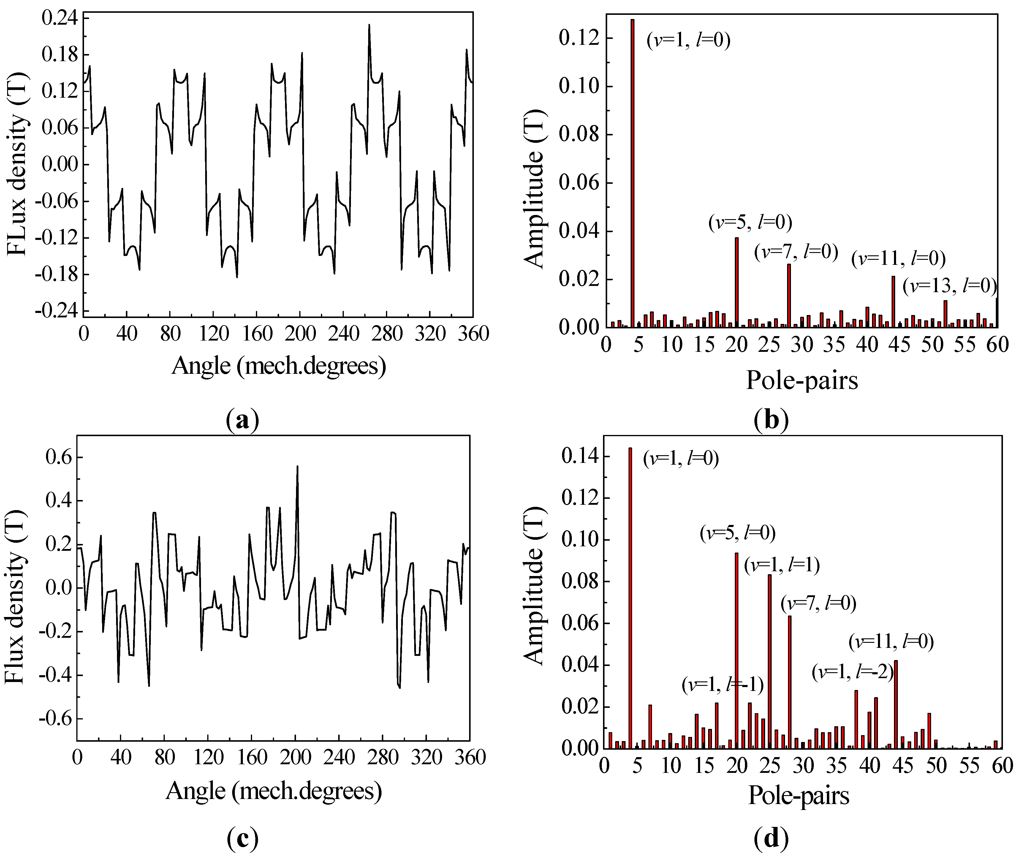
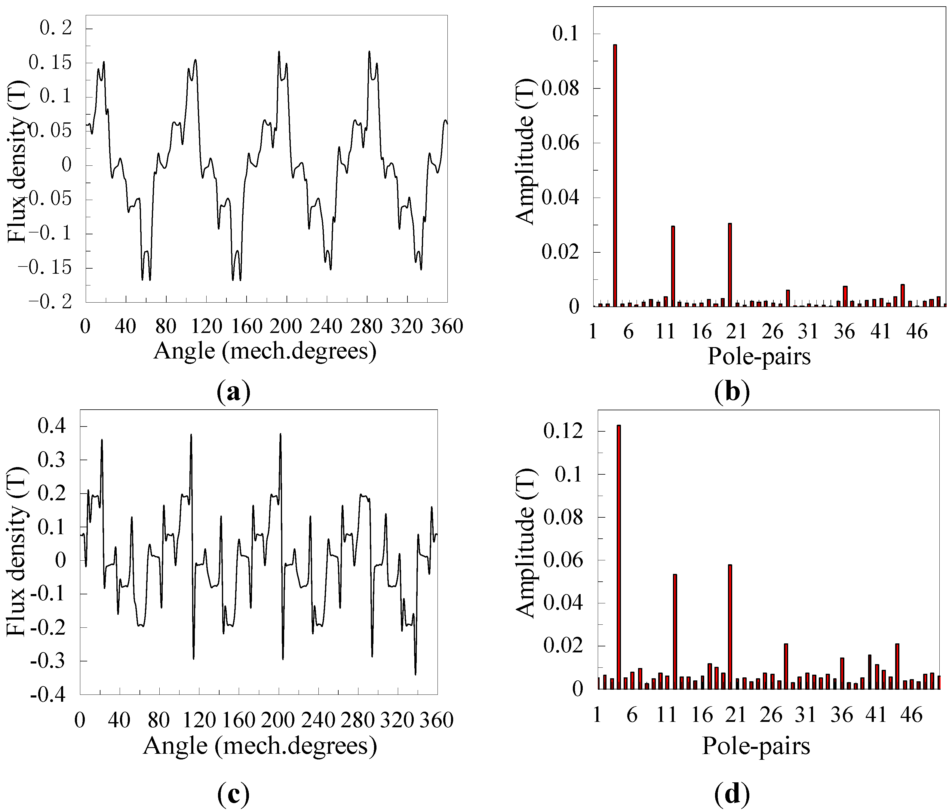
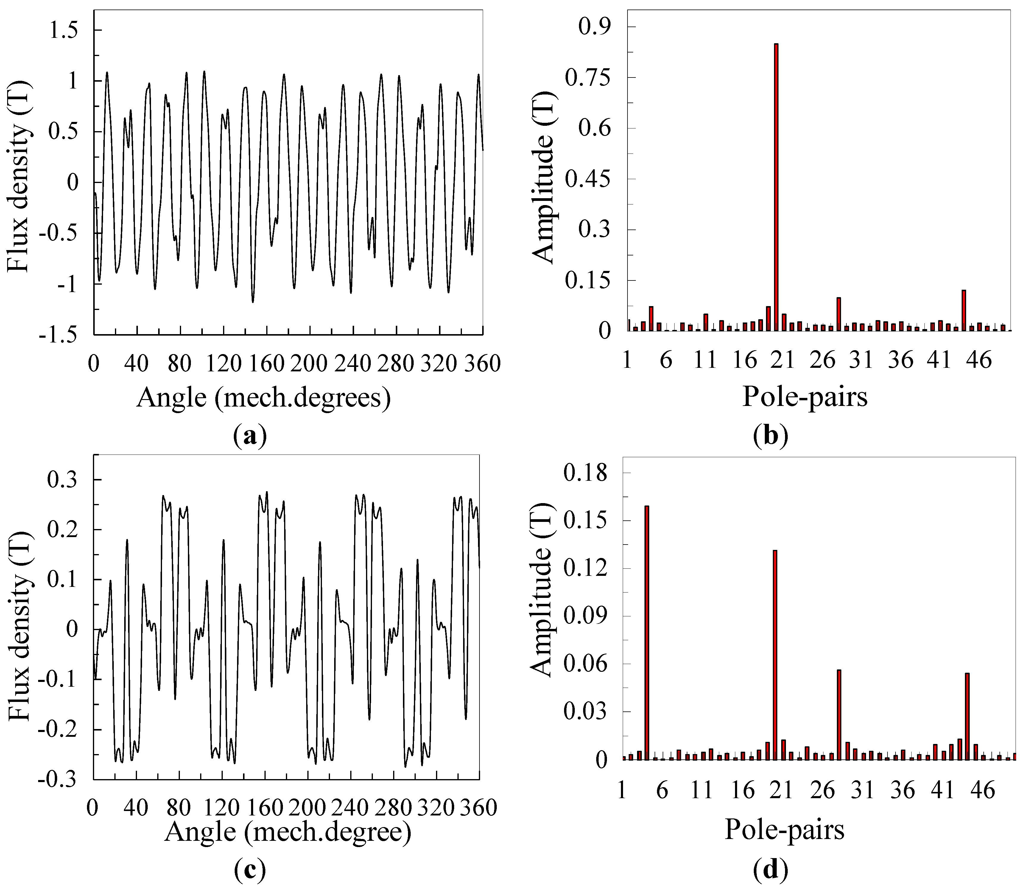
3.1. Flux Density Waveform and Harmonics Analysis

Figure 3 shows the axial flux density waveforms due to the permanent magnet rotor in the air gap adjacent to the stator and corresponding space harmonic spectra. The major harmonic before modulation is the natural space harmonic with the pole-pair number 17 (h = 1, k = 0). It can be seen that the presence of the modulating ring rotor results in a number of modulated space harmonics, viz. k ≠ 0. The major modulated space harmonics with the pole-pair number 4 (h = 1, k = −1), 25 (h = 1, k = −2) and 38 (h = 1, k = 1) are effective harmonics, the largest of which (h = 1, k = −1) has the same number of pole pairs with the stator.
Figure 3. Axial flux density waveforms due to the permanent magnet rotor, in the air gap adjacent to the stator and corresponding space harmonic spectra: (a) axial flux density waveform without the modulating ring rotor; (b) the space harmonic spectrum without the modulating ring rotor; (c) axial flux density waveform with the modulating ring rotor; and (d) the space harmonic spectrum with the modulating ring rotor.
Energies 06 04799 g003
Figure 4 shows the axial flux density waveforms due to the stator winding in the air gap adjacent to the stator and corresponding space harmonic spectra. Without the modulating ring rotor, the major harmonics with the pole-pair number 4 (v = 1, l = 0), 20 (v = 5, l = 0), 28 (v = 7, l = 0), 44 (v = 11, l = 0) and 52 (v = 13, l = 0) are natural space harmonics, viz. l = 0. The presence of the modulating ring rotor results in a number of modulated space harmonics, and the major modulated space harmonics with the pole-pair number 17(v = 1, l = −1), 25 (v = 1, l = 1) and 38 (v = 1, l = −2) are effective harmonics.
Figure 4. Axial flux density waveforms due to the stator winding, in the air gap adjacent to the stator and corresponding space harmonic spectra: (a) axial flux density waveform without the modulating ring rotor; (b) the space harmonic spectrum without the modulating ring rotor; (c) axial flux density waveform with the modulating ring rotor; and (d) the space harmonic spectrum with the modulating ring rotor.
Energies 06 04799 g004
From theoretical analysis summarized in Equation (27), the space harmonics produced by the permanent magnet rotor with the pole-pair number 4 (h = 1, k = −1), 17 (h = 1, k = 0), 25 (h = 1, k = −2) and 38 (h = 1, k = 1) interact with the space harmonics produced by the stator winding with the pole-pair number 4 (v = 1, l = 0), 17 (v = 1, l = −1), 25 (v = 1, l = 1) and 38 (v = 1, l = −2), contributing to torque transmission in the air gap adjacent to the stator. It is notable that the largest modulated space harmonic magnetic field with the pole-pair number 4 (h = 1, k = −1) produced by the permanent magnet rotor matches with the main magnetic field produced by the stator winding so that the main torque in the air gap adjacent to the stator is obtained.
Figure 5 shows the axial flux density waveforms due to the permanent magnet rotor in the air gap adjacent to the permanent magnet rotor and corresponding space harmonic spectra. The major harmonic before modulation is the natural space harmonic with the pole-pair number 17 (h = 1, k = 0). It can be seen that the presence of the modulating ring rotor results in a number of modulated space harmonics, viz. k ≠ 0. The major modulated space harmonics with the pole-pair number 4 (h = 1, k = −1) and 38 (h = 1, k = 1) are effective harmonics.
Figure 5. Axial flux density waveforms due to the permanent magnet rotor, in the air gap adjacent to the permanent magnet rotor and corresponding space harmonic spectra: (a) axial flux density waveform without the modulating ring rotor; (b) the space harmonic spectrum without the modulating ring rotor; (c) axial flux density waveform with the modulating ring rotor; and (d) the space harmonic spectrum with the modulating ring rotor.
Energies 06 04799 g005
Figure 6 shows the axial flux density waveforms due to the stator winding in the air gap adjacent to the permanent magnet rotor and corresponding space harmonic spectra. Without the modulating ring rotor, the major harmonics with the pole-pair number 4 (v = 1, l = 0), 20 (v = 5, l = 0), 28 (v = 7, l = 0), 44 (v = 11, l = 0) and 52 (v = 13, l = 0) are natural space harmonics, viz. l = 0. The presence of the modulating ring rotor results in a number of modulated space harmonics, and the largest modulated space harmonic with the pole-pair number 17 (v = 1, l = −1) is effective harmonic, which has the same number of pole pairs with the permanent magnet rotor.
From theoretical analysis summarized in Equation (27), the space harmonics produced by the permanent magnet rotor with the pole-pair number 4 (h = 1, k = −1) and 17 (h = 1, k = 0) interact with the space harmonics produced by the stator winding with the pole-pair number 4 (v = 1, l = 0) and 17 (v = 1, l = −1), contributing to torque transmission in the air gap adjacent to the permanent magnet rotor. It is notable that the largest modulated space harmonic magnetic field with the pole-pair number 17 (h = 1, k = −1) produced by the stator winding matches with the main magnetic field produced by the permanent magnet rotor so that the main torque in the air gap adjacent to the permanent magnet rotor is obtained.
Figure 6. Axial flux density waveforms due to the stator winding, in the air gap adjacent to the permanent magnet rotor and corresponding space harmonic spectra: (a) axial flux density waveform without the modulating ring rotor; (b) the space harmonic spectrum without the modulating ring rotor; (c) axial flux density waveform with the modulating ring rotor; and (d) the space harmonic spectrum with the modulating ring rotor.
Energies 06 04799 g006

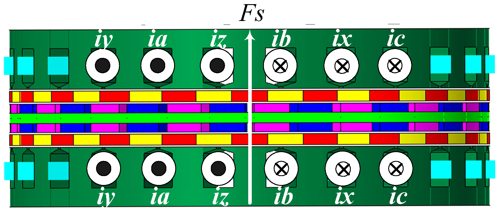
3.2. Operating Principle

As the number of pole pairs of the permanent magnet rotor is not equal to the number of pole pairs of the stator with the existence of the modulating ring rotor, initial positions of the magnetic fields produced by the stator winding and the permanent magnet rotor should be predetermined properly to produce large torque. The static performance of the axial MFM-BDRM is evaluated by holding the modulating ring rotor still, feeding the stator winding with DC current of i a = I m , i b = i c = I m 2 and incrementally rotating the permanent magnet rotor. The permanent magnet rotor is rotated two full pole pitches. The initial position of the resultant magnetic field produced by the stator winding coincides with the q axis, as shown in Figure 7.
Figure 7. Initial position of the resultant magnetic field produced by the stator winding.
Energies 06 04799 g007
The torque-angle curves are shown in Figure 8. It can be seen that the torque waveforms vary sinusoidally with the angles. Moreover, there is a π difference between the phase angles of the permanent magnet rotor and the modulating ring rotor. The torque ratio of the modulating ring rotor with respect to the permanent rotor is very close to −21/17 at any rotor angle, which well agrees with Equation (30). The torque on the modulating ring rotor reaches the peak value at slip angle of 0 degree where the position of the resultant magnetic field produced by the stator winding coincides with the q axis. It means that id = 0 control strategy is suitable for the axial MFM-BDRM to get the maximum torque transmission capability.
Figure 8. Torque-angle curves.
Energies 06 04799 g008
In order to evaluate the transient performance of the axial MFM-BDRM, high-speed operation mode is selected for simulation. Figure 9 shows three-phase no-load back electromotive force (EMF) waveforms and electromagnetic torque waveforms of the three parts. It can be seen that the frequency of the no-load back EMF is the same as 2050/3 Hz when the permanent magnet rotor operates at the rotational speed of 5000 rpm and the modulating ring rotor operates at the rotational speed of 6000 rpm, which agrees with the operating principle of Equation (24). After that, the stator winding is fed with three-phase rated current at the frequency of 2050/3 Hz, viz. ωs = 10,250 rpm, to meet the operation demand. It can be found that stable torque transmission can be achieved. The electromagnetic torque on the modulating ring rotor, on the permanent magnet rotor and on the stator is 62.71 Nm, −50.44 Nm and −12.27 Nm, respectively. The torque ratio of the modulating ring rotor with respect to the permanent rotor is −1.24, approximately equal to −21/17. As will be evident from Figure 9, the axial MFM-BDRM can realize speed decoupling between the permanent magnet rotor and the modulating ring rotor by adjusting the frequency of the stator winding. Moreover, the machine can transfer torque by a torque ratio.
Figure 9. No-load back electromotive force (EMF) waveforms and torque transfer waveforms: (a) no-load back EMF waveforms; and (b) torque transfer waveforms.
Energies 06 04799 g009

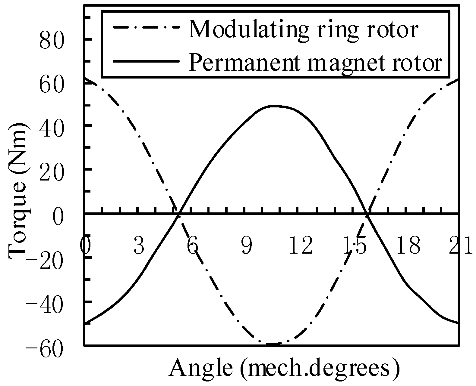
3.3. Torque Transmission

Figure 10 shows how the electromagnetic torque and torque ratio vary with the number of pole pairs of the permanent magnet rotor when the number of stator pole pairs remains to be 4. Each model is simulated under the condition that the permanent magnet rotor operates at the rotational speed of 5000 rpm and the modulating ring rotor operates at the rotational speed of 6000 rpm. The same stator structure, the same number of winding turns per phase and the same overall dimension are presumed. The electromagnetic torque on the modulating ring rotor increases with the number of pole pairs of the permanent magnet rotor. Absolute value of the electromagnetic torque on the permanent magnet rotor increases with the number of pole pairs of the permanent magnet rotor as well. It is evident that the simulation value coincides exactly with the theoretical value. Therefore, the validity of Equation (30) is assessed.
Figure 10. Torque transmission characteristics: (a) variation of torque with the number of pole pairs of the permanent magnet (PM) rotor; and (b) Variation of torque ratio with the number of pole pairs of the PM rotor.
Energies 06 04799 g010

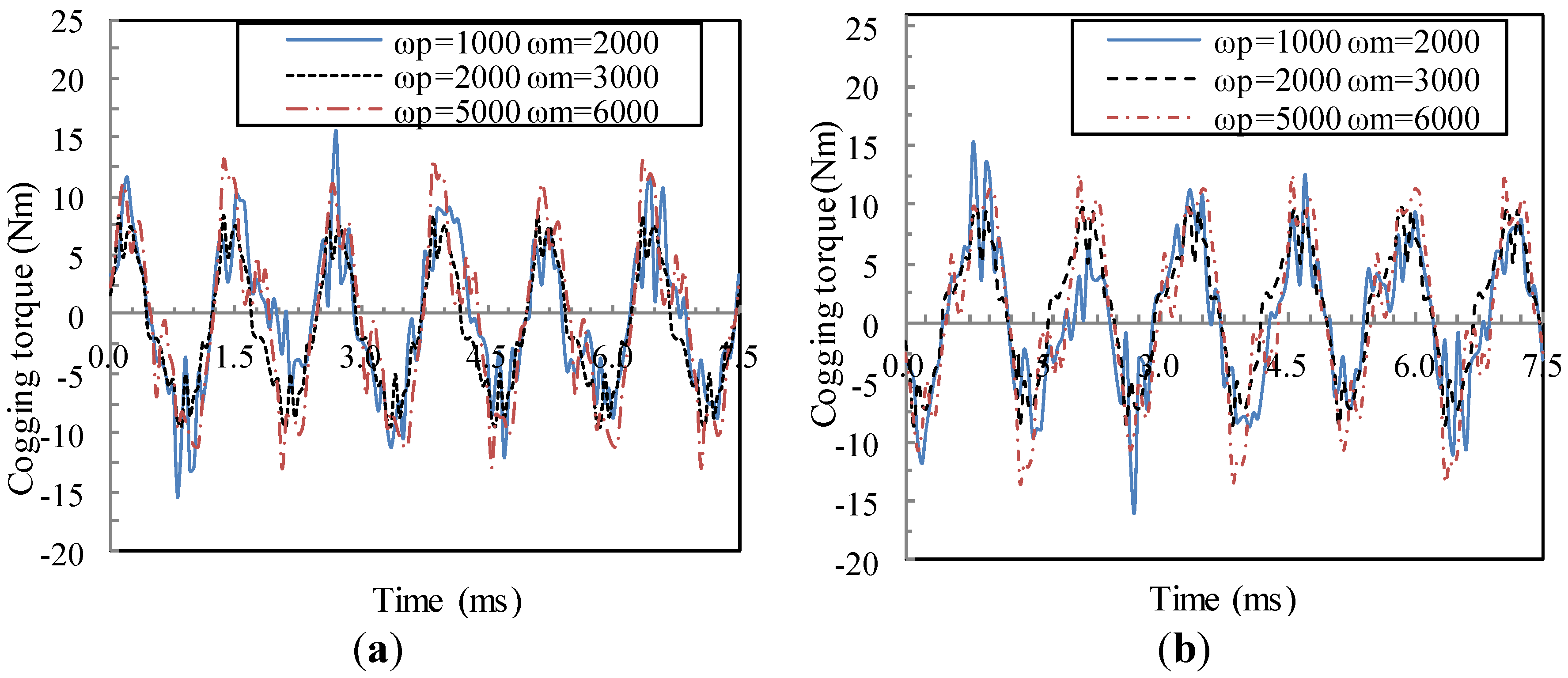
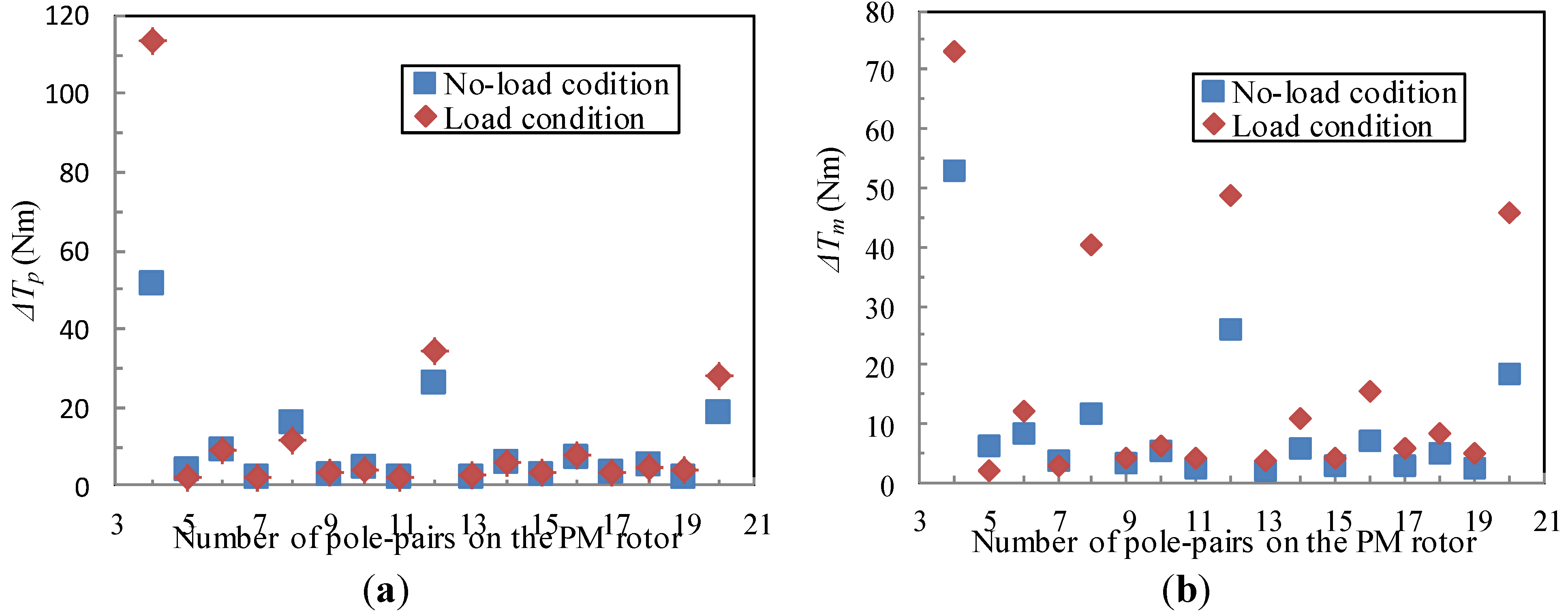
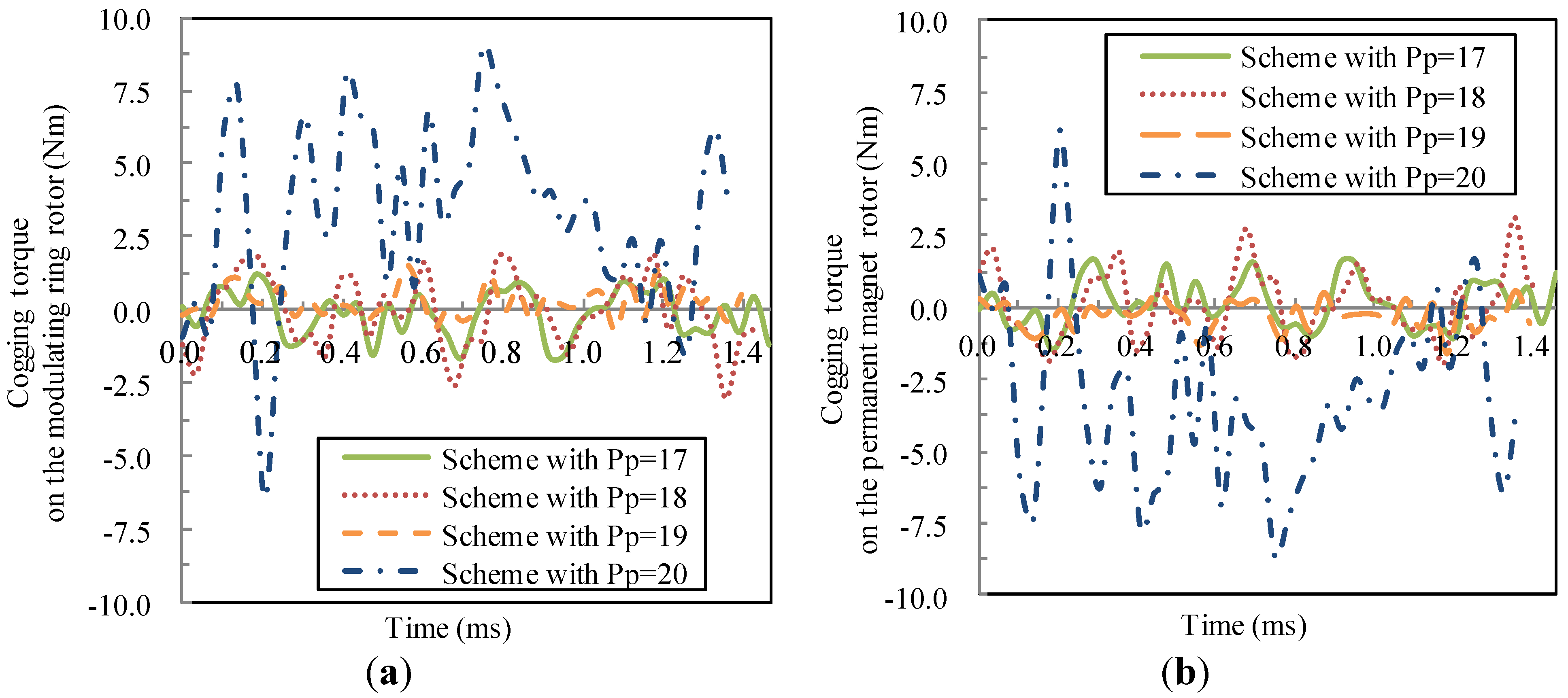
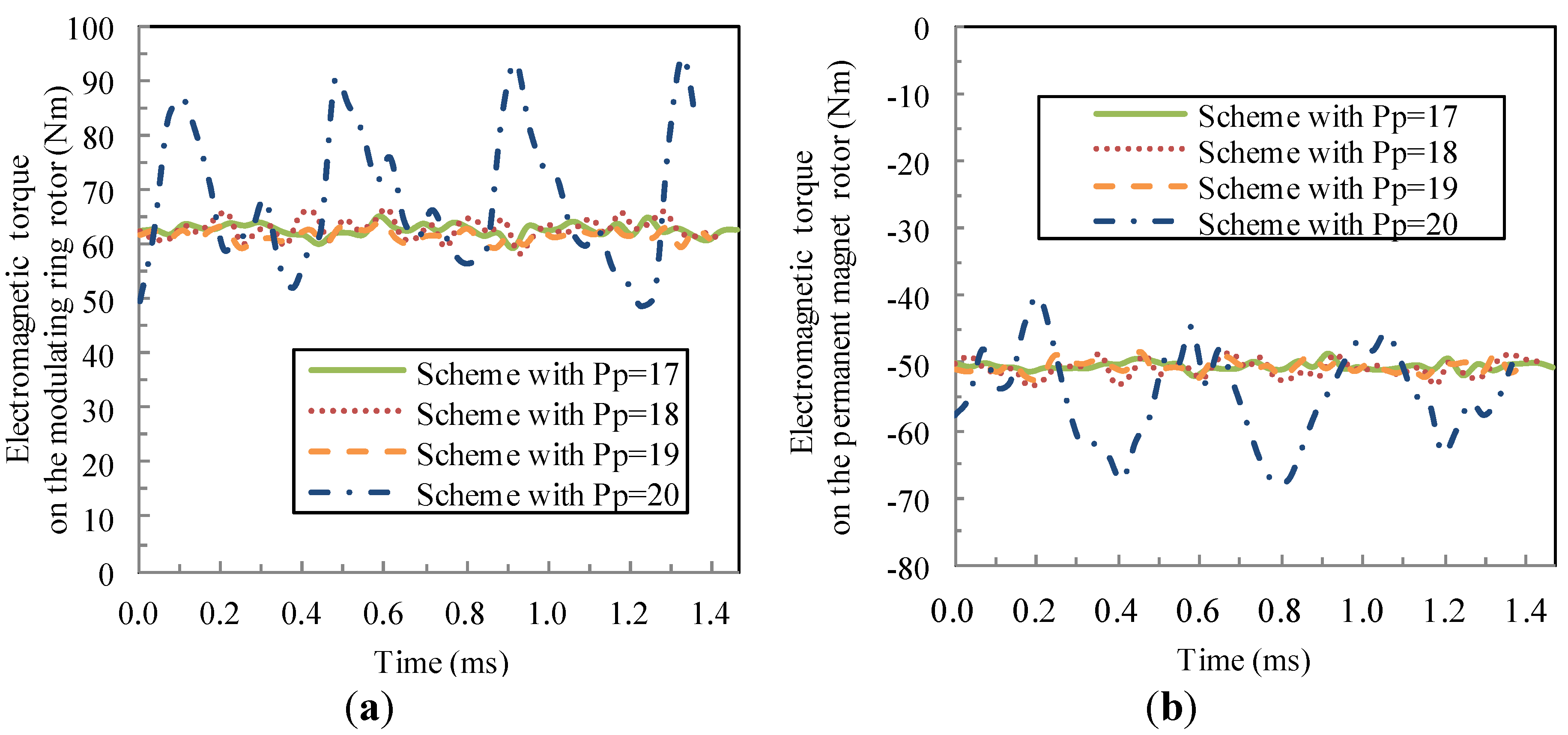
3.4. Torque Ripple Characteristics

Model with the number of pole pairs of the permanent magnet rotor being 12 and the number of ferromagnetic pole pieces being 16 is selected to evaluate the theoretical analysis of the cogging torque. The permanent magnet rotor operates at the rotational speed of 5000 rpm and the modulating ring rotor operates at the rotational speed of 6000 rpm. It means that the rotation angles of two rotors differ by 2π when the rotation time is 0.06 s. The cogging torque waveforms of the two parts are presented in Figure 11. It can be found that the fundamental order of the cogging torque on the permanent magnet rotor is 48 and the same goes with the cogging torque on the modulating ring rotor. The cogging toque on the permanent magnet rotor and the cogging torque on the modulating ring rotor are approximately equal and opposite. As the least common multiple between pm and 2pp is also 48, the fundamental order of the cogging torque is equal to the least common multiple between pm and 2pp. Therefore, Equation (44) is verified through 3D FEM.
Figure 11. Cogging torque waveforms: (a) cogging toque waveform of the permanent magnet rotor; and (b) cogging torque waveform of the modulating ring rotor.
Energies 06 04799 g011
Figure 12 is the cogging torque waveforms with three different circumstances. The first circumstance is the rotational speed of the permanent magnet rotor being 1000 rpm and that of the modulating ring rotor being 2000 rpm. The second circumstance is the rotational speed of the permanent magnet rotor being 2000 rpm and that of the modulating ring rotor being 3000 rpm. The third circumstance is the rotational speed of the permanent magnet rotor being 5000 rpm and that of the modulating ring rotor being 6000 rpm. From Equation (48), the cogging torque periods of three circumstances are calculated as follows:
  • when ωp = 1000 rpm, ωm = 2000 rpm: c d = 2 × 12 × 1000 16 × 2000 = 3 4    c min = 3     t c o g = 3 30 12 × 1000 s = 7 . 5  ms ;
  • when ωp = 2000 rpm, ωm = 3000 rpm: c d = 2 × 12 × 2000 16 × 3000 = 1 1    c min = 1     t c o g = 30 12 × 2000 s = 1 . 25  ms ;
  • when ωp = 5000 rpm, ωm = 6000 rpm: c d = 2 × 12 × 5000 16 × 6000 = 5 4    c min = 5     t c o g = 5 30 12 × 5000 s = 2 . 5  ms .
Figure 12. Cogging torque waveforms: (a) cogging toque waveform of the permanent magnet rotor; and (b) cogging torque waveform of the modulating ring rotor.
Energies 06 04799 g012
As will be evident from Figure 12, the time when cogging torque waveforms periodically repeat for three circumstances is 7.5 ms, 1.25 ms and 2.5 ms, respectively. The simulation result agrees with the calculated result, which demonstrates the validity of Equation (48). Moreover, waveforms of the three circumstances all fluctuate 6 times within 7.5 ms. It means that waveforms of the three circumstances will fluctuate 48 times within 0.06 s, which coincides exactly with Equation (44). It can be seen that the rotational speeds of two rotors have an influence on the waveform of the cogging torque.
Figure 13 shows how the cogging torque varies with the number of pole pairs of the permanent magnet rotor when the number of stator pole pairs remains to be 4. Each model is simulated under the condition that the permanent magnet rotor operates at the rotational speed of 5000 rpm and the modulating ring rotor operates at the rotational speed of 6000 rpm. The same stator structure, the same number of winding turns per phase and the same overall dimension are presumed. Moreover, L C M ( p m , 2 p p ) 2 p p is also marked on Figure 13. Clearly, there is good correlation between the cogging torque and L C M ( p m , 2 p p ) 2 p p . The smaller L C M ( p m , 2 p p ) 2 p p is, the larger will be the cogging toque. Model with the number of pole pairs of the permanent magnet rotor being 4 has the minimum value of L C M ( p m , 2 p p ) 2 p p , viz. 1, and the maximum value of ΔTp and ΔTm. Models with the greatest common divisor between the pole-pair number on the permanent magnet rotor and the pole-pair number on the stator 1 exhibit low ΔTp and ΔTm.
Figure 13. Variation of cogging torque and L C M ( p m , 2 p p ) 2 p p with the number of pole pairs of the PM rotor.
Energies 06 04799 g013
Electromagnetic torque ripple is estimated by the ΔT difference under the no-load condition and load condition. Figure 14 shows how ΔTp and ΔTm vary with the number of pole pairs of the permanent magnet rotor when the number of stator pole pairs remains to be 4. Each model is simulated under the condition that the permanent magnet rotor operates at the rotational speed of 5000 rpm and the modulating ring rotor operates at the rotational speed of 6000 rpm. The same stator structure, the same number of winding turns per phase and the same overall dimension are presumed. ΔTp under no-load condition is almost the same with ΔTp under load condition, except for models with the number of pole pairs of the permanent magnet rotor being 4, 8, 12 and 20. Moreover, there is non-ignorable difference between ΔTm under no-load condition and ΔTm under load condition for models with the number of pole pairs of the permanent magnet rotor being 4, 8, 12 and 20. It can be seen clearly that models with the number of pole pairs of the permanent magnet rotor being 4, 8, 12 and 20 have significant electromagnetic torque ripple.
Figure 14. Variation of ΔTp and ΔTm with the number of pole pairs of the PM rotor: (a) ΔTp and (b) ΔTm.
Energies 06 04799 g014
The circumstances predicted for significant electromagnetic torque ripple and constraints are listed in Table 1. Obviously, models that satisfy the circumstances listed in Table 1 coincide with simulation results with prominent electromagnetic torque ripple.
Table 1. Circumstance for significant electromagnetic torque ripple and constraint.
CircumstanceConstraintModel with pp in study
pp = 3g·ps, g = 1, 2, 3…pp(1, 1) = ps(6g+1, 0) p p ω p + p m ω m p p + p m ω s 6 g + 1 12
pp = (3g − 1)ps, g = 1, 3, 5…pp(1, 1) = ps(6g−1, 0) p p ω p + p m ω m p p + p m ω s 6 g 1 8
pp = (3g − 1)ps, g = 2, 4, 6…pp = ps(3g-1, 0) ω p ω s 3 g 1
pp(1, 1) = ps(6g−1, 0) p p ω p + p m ω m p p + p m ω s 6 g 1
20
pp = (3g + 1)ps, g = 0, 2, 4…pp = ps(3g+1) ω p ω s 3 g + 1 4

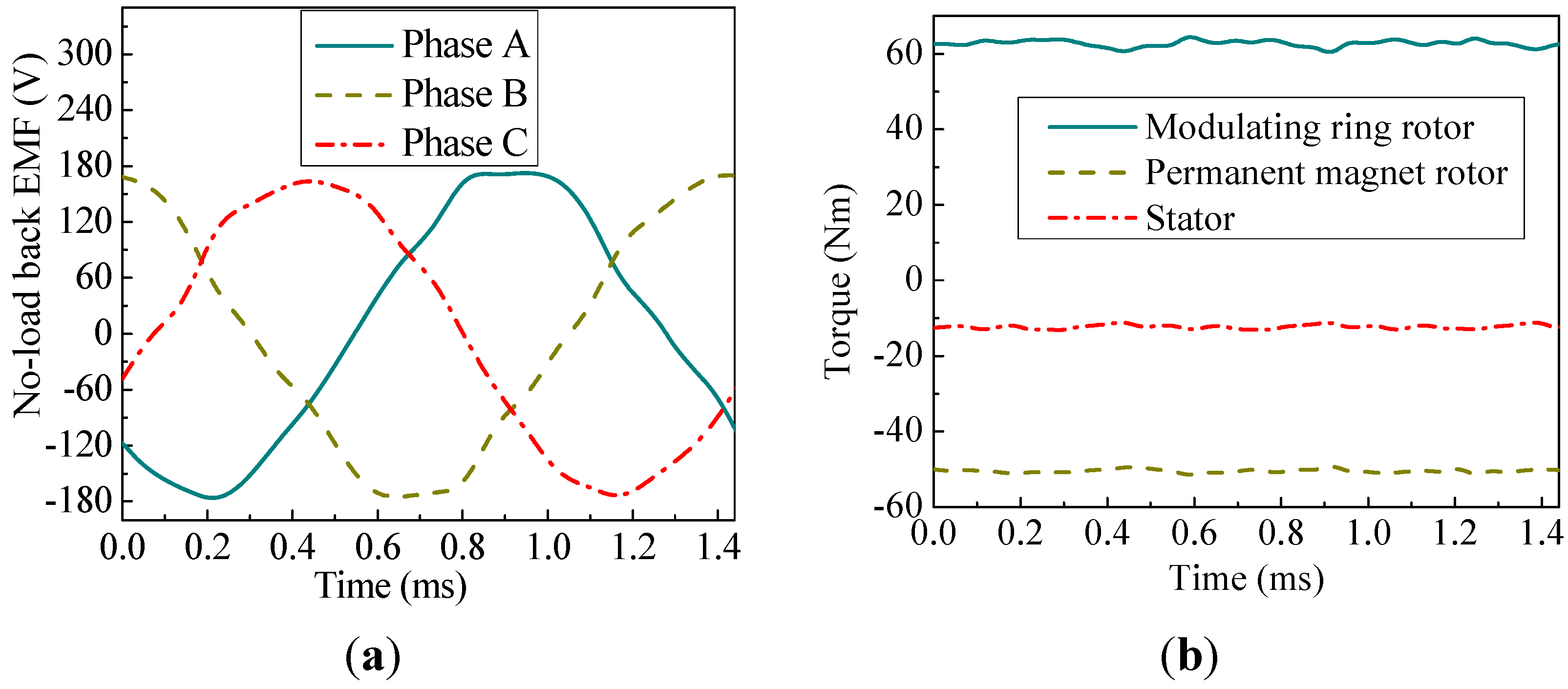
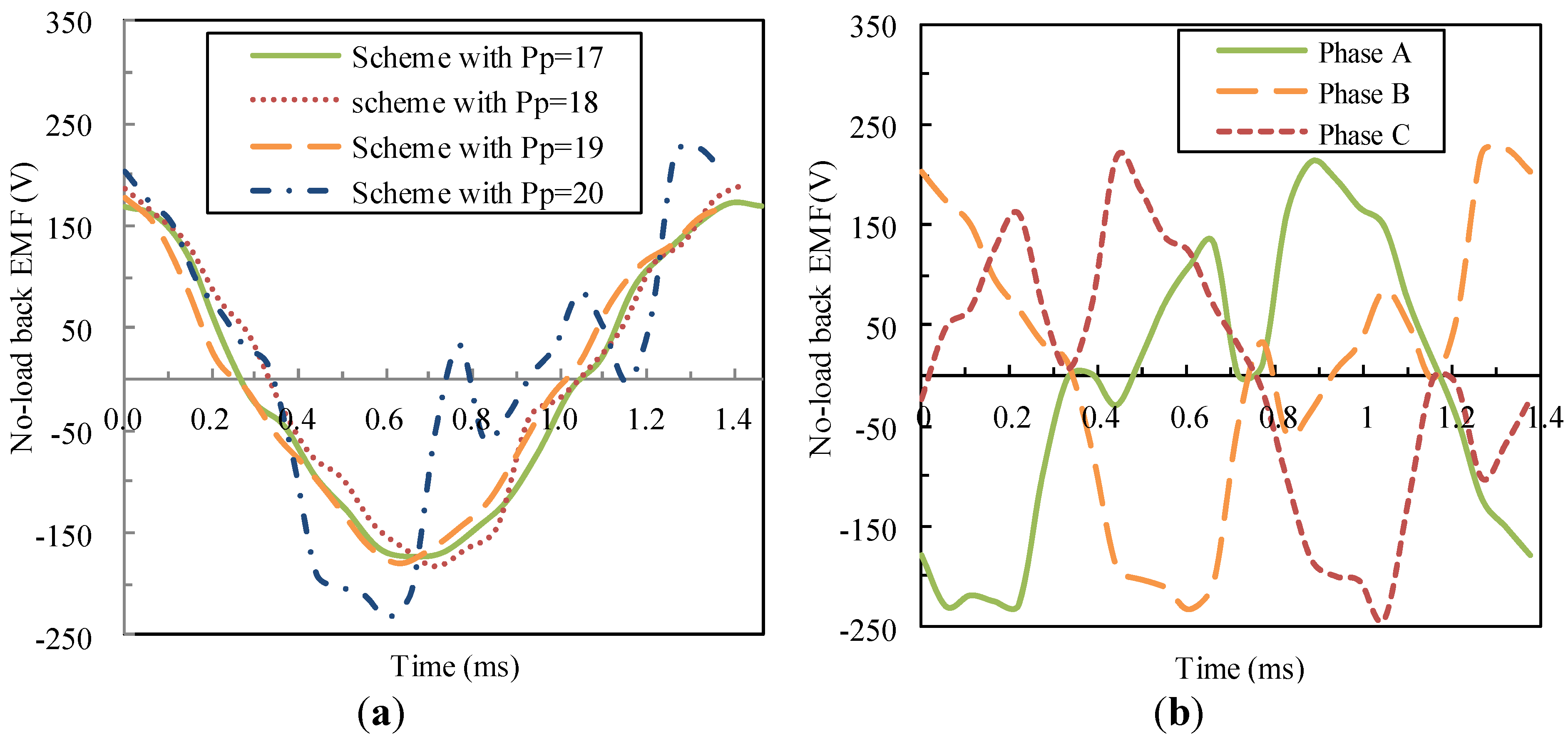
3.5. Operation Performance

When the number of stator pole pairs remains to be 4, four schemes with the number of pole pairs of the permanent magnet rotor being 17, 18, 19 and 20 are compared for the performance evaluation. Figure 15 shows no-load back EMF waveforms. It can be seen from Figure 15b that the waveforms of three phases are asymmetrical and distorted seriously for the scheme with pp = 20.
Figure 15. No-load back EMF waveforms: (a) one-phase no-load back EMF waveforms for four schemes; and (b) three-phase no-load back EMF waveforms for the scheme with pp = 20.
Energies 06 04799 g015
Figure 16 shows cogging torque waveforms for the four schemes. It can be found that the cogging toque on the permanent magnet rotor and that on the modulating ring rotor are approximately equal and opposite for each scheme. Cogging torque for the scheme with pp = 20 is much larger than the other three schemes.
Figure 16. Cogging torque waveforms: (a) cogging torque on the modulating ring rotor; and (b) cogging torque on the permanent magnet rotor.
Energies 06 04799 g016
Electromagnetic torque waveforms for the four schemes are shown in Figure 17. It can be found that the torque ripple for the scheme with pp = 20 is very significant.
Figure 17. Electromagnetic torque waveforms: (a) electromagnetic torque on the modulating ring rotor; and (b) electromagnetic torque on the permanent magnet rotor.
Energies 06 04799 g017
Performance comparison for the four schemes is listed in Table 2. In consideration of the total harmonic distortion (THD) of no-load back EMF, the schemes with pp = 17 and pp = 19 are pretty good, while the scheme with pp = 20 is worst. In consideration of ΔTp and ΔTm under no-load condition, the best scheme is that with pp = 19, and then pp = 17, and then pp = 18, and the scheme with pp = 20 is the worst. L C M ( p m , 2 p p ) 2 p p from large to small in order is the scheme with pp = 19, the scheme with pp = 17, the scheme with pp = 18 and the scheme with pp = 20. When L C M ( p m , 2 p p ) 2 p p is smaller, the cogging torque is larger. Cogging torque for the scheme with pp = 20 is 7 times as large as the scheme with pp = 19. Under load condition, the torque ripple on the modulating ring for the scheme with pp = 20 is approximately seven times as high as the other schemes, which is in accordance with electromagnetic torque ripple analysis.
Table 2. Performance comparison.
Schemepp = 17pp = 18pp = 19pp = 20
RMS value of A-phase no-load back EMF (V)122.8127.1123.1126.2
THD of no-load back EMF (%)7.1412.058.146.27
ΔTp under no-load condition (Nm)3.135.12.1914.85
ΔTm under no-load condition (Nm)3.04.972.2715.45
LCM(pm, 2pp)/2pp2111233
Average torque on the modulating ring rotor (Nm)62.7162.9461.7168.33
Torque ripple on the modulating ring rotor (%)4.686.543.9033.62
Average torque on the permanent magnet rotor (Nm)−50.44−50.76−50.51−54.91
Torque ripple on the permanent magnet rotor (%)3.354.754.0125.35
As will be evident from Table 2, the combination between the number of pole pairs of the permanent magnet rotor and that of the stator affects the electromagnetic torque ripple of the axial MFM-BDRM greatly.
Figure 18 shows the axial flux density waveforms due to the permanent magnet rotor in two air gaps and corresponding space harmonic spectra. The space harmonic with the pole-pair number 20 (h = 1, k = 0) is the major harmonic in either air gap with the rotational speed ωp. The space harmonic with the pole-pair number 44 (h = 1, k = 1) is the dominant harmonic in either air gap with the rotational speed p p ω p + p m ω m p p + p m .
Figure 19 shows the axial flux density waveforms due to the stator winding in two air gaps and corresponding space harmonic spectra. The space harmonic with the pole-pair number 20 (v = 5, l = 0) is the major harmonic in either air gap with the rotational speed ω s 5 . The space harmonic with the pole-pair number 44 (v = 11, l = 0) is the dominant harmonic in either air gap with the rotational speed ω s 11 .
Figure 18. Axial flux density waveforms due to the permanent magnet rotor, in two air gaps and corresponding space harmonic spectra: (a) axial flux density waveform in the air gap adjacent to the permanent magnet rotor; (b) the space harmonic spectrum in the air gap adjacent to the permanent magnet rotor; (c) axial flux density waveform in the air gap adjacent to the stator; and (d) the space harmonic spectrum in the air gap adjacent to the stator.
Energies 06 04799 g018
Since the space harmonic with the pole-pair number 20 produced by the permanent magnet rotor and the space harmonic with the pole-pair number 20 produced by the stator winding have the same pole-pair number but different rotational speeds, torque ripple in either air gap arises under the load operation. As the two space harmonics with the pole-pair number 20 have large amplitudes, their interaction will contribute to high electromagnetic torque ripple. Similarly, the space harmonic with the pole-pair number 40 produced by the permanent magnet rotor interact with the space harmonic with the pole-pair number 40 produced by the stator winding, resulting in significant electromagnetic torque ripple in either air gap under the load operation as well.
Therefore, care must be taken to note that the adoption of the scheme that the greatest common divisor between the pole-pair number on the permanent magnet rotor and the pole-pair number on the stator is 1 can have satisfactory operation performance.
Figure 19. Axial flux density waveforms due to the stator winding, in two air gaps and corresponding space harmonic spectra: (a) axial flux density waveform in the air gap adjacent to the permanent magnet rotor; (b) the space harmonic spectrum in the air gap adjacent to the permanent magnet rotor; (c) axial flux density waveform in the air gap adjacent to the stator; and (d) the space harmonic spectrum in the air gap adjacent to the stator.
Energies 06 04799 g019

4. Conclusions

In this paper, a novel brushless double-rotor machine, viz. the axial MFM-BDRM, has been proposed.
(1)
The matching relation of ps, pp and pm, and the relation of ωs, ωp and ωm have been deduced. It is found that the axial MFM-BDRM provides speed difference between the shaft of the modulating ring rotor and that of the permanent magnet rotor by adjusting the frequency of stator winding current.
(2)
The torque transmission relation has been deduced. The result shows that the axial MFM-BDRM transfers torque by a certain torque ratio.
(3)
The cogging torque characteristics have been mathematically formulated. The result demonstrates that the order of the cogging torque is LCM (pm, 2pp) and there is good correlation between the amplitude of cogging torque and L C M ( p m , 2 p p ) 2 p p . The smaller L C M ( p m , 2 p p ) 2 p p is, the larger the cogging toque will be.
(4)
The performance analysis verifies that the adoption of the scheme that the greatest common divisor between the pole-pair number of the permanent magnet rotor and that of the stator is 1 can prominently reduce torque ripple and make the no-load back EMF more sinusoid, resulting in good performance of the machine.

Nomenclature:

pp
number of pole pairs of the permanent magnet rotor
ps
number of pole pairs of the stator
pm
number of ferromagnetic pole pieces
ωp
rotational speed of the permanent magnet rotor
ωs
rotational speed of the stator magnetic field
ωm
rotational speed of the modulating ring rotor
θop
initial phase angle of the permanent magnet rotor
θom
initial phase angle of the modulating ring rotor
θos
initial phase angle of the stator magnetic field
pp(h, k), ωp(h, k)
number of pole pairs in the space harmonic magnetic field distribution produced by the permanent magnet rotor and its rotational speed
ps(v, l), ωs(v, l)
number of pole pairs in the space harmonic magnetic field distribution produced by the stator winding and its rotational speed
Tp
electromagnetic torque on the permanent magnet rotor
Ts
electromagnetic torque on the stator
Tm
electromagnetic torque on the modulating ring rotor
Tcog
cogging torque of interaction between the permanent magnet rotor and ferromagnetic pole pieces of the modulating ring rotor
W
total magnetic energy
B
magnetic flux density in the air gap adjacent to the permanent magnet rotor
V
volume of the air gap adjacent to the permanent magnet rotor
Α
relative position angle between the permanent magnet rotor and modulating ring rotor
Ri
inner radius of the axial MFM-BDRM
Ro
outer radius of the axial MFM-BDRM
δ
length of the air gap adjacent to the permanent magnet rotor
Δθp
rotation angle of the permanent magnet rotor
Δθm
rotation angle of the modulating ring rotor
tcog
period of the cogging torque waveform
LCM(pm, 2pp)
the least common multiple between pm and 2pp
fph(z)
Fourier coefficient for the magnetomotive force produced by the permanent magnet rotor
FA(z, θ, t)
magnetomotive force produced by A-phase winding
FB(z, θ, t)
magnetomotive force produced by B-phase winding
FC(z, θ, t)
magnetomotive force produced by C-phase winding
fsv(z)
Fourier coefficient for the magnetomotive force produced by one-phase winding
bph(z)
Fourier coefficient for the axial component of the flux density distribution produced by the permanent magnet rotor without the modulating ring rotor
bsv(z)
Fourier coefficient for the axial component of the flux density distribution produced by the stator winding without the modulating ring rotor
λ0(z), λj(z)
Fourier coefficient for the modulating function
B0, Bh
Fourier coefficient for the square of flux density produced by the permanent magnet rotor along z axis without the modulating ring rotor
G0, Gj
Fourier coefficient for the square of the modulating function
ΔT
torque difference between the maximum and minimum value
ΔTp
ΔT of the permanent magnet rotor
ΔTm
ΔT of the modulating ring rotor

Acknowledgments

This work was supported in part by National Natural Science Foundation of China under Project 50877013 and 51077026, in part by the 863 Plan of China under Project 2011AA11A261, and in part by the Fundamental Research Funds for the Central Universities (Grant No. HIT.BRET1.2010013).

Conflicts of Interest

The authors declare no conflict of interest.

References

  1. Ehsani, M.; Gao, Y.; Miller, J.M. Hybrid electric vehicles: Architecture and motor drives. IEEE Proc. 2007, 95, 719–720. [Google Scholar] [CrossRef]
  2. Chau, K.T.; Chan, C.C. Emerging energy-efficient technologies for hybrid electric vehicles. IEEE Proc. 2007, 95, 821–835. [Google Scholar] [CrossRef]
  3. Magnussen, F.; Sadarangani, C. Electromagnetic Transducer for Hybrid Electric Vehicles. In Proceedings of the Nordic Workshop on Power and Industrial Electronics, Stockholm, Sweden, 12–14 August 2002; pp. 5–6.
  4. Magnussen, F.; Thelin, P.; Sadarangani, C. Design of Compact Permanent Magnet Machines for a Novel HEV Propulsion System. In Proceedings of the 20th International Electric Vehicle Symposium and Exposition (EVS), Long Beach, CA, USA, 15–19 November 2003; pp. 1–12.
  5. Nordlund, E.; Eriksson, S. Test and Verification of a Four-Quadrant Transducer for HEV Applications. In Proceedings of the IEEE Vehicle Power and Propulsion Conference, Chicago, IL, USA, 2–5 September 2005; pp. 37–41.
  6. Zheng, P.; Liu, R.R.; Thelin, P.; Nordlund, E.; Sadarangani, C. Research on the parameters and performances of a 4QT prototype machine used for HEV. IEEE Trans. Magn. 2007, 43, 443–446. [Google Scholar] [CrossRef]
  7. Sun, X.K.; Cheng, M. Thermal analysis and cooling system design of dual mechanical port machine for wind power application. IEEE Trans. Magn. 2013, 60, 1724–1733. [Google Scholar]
  8. Frank, N.W.; Toliyat, H.A. Gearing Ratios of a Magnetic Gear for Wind Turbines. In Proceedings of the Electric Machines and Drives Conference (IEMDC ’09), Miami, FL, USA, 3–6 May 2009; pp. 1224–1230.
  9. Frank, N.W.; Toliyat, H.A. Gearing Ratios of a Magnetic Gear for Marine Applications. In Proceedings of the Electric Ship Technologies Symposium (ESTS 2009), Baltimore, MD, USA, 20–22 April 2009; pp. 477–481.
  10. Zheng, P.; Liu, R.R.; Wu, Q.; Tong, C.D.; Tang, Z.J. Compound-Structure Permanent-Magnet Synchronous Machine Used for HEVs. In Proceedings of the International Conference on Electric Machines and Systems (ICEMS 2008), Wuhan, China, 17–20 October 2008; pp. 2916–2920.
  11. Eriksson, S.; Sadarangani, C. A Four-Quadrant HEV Drive System. In Proceedings of the IEEE 56th Vehicular Technology Conference (VTC 2002), Vancouver, BC, Canada, 24–28 September 2002; Volume 3, pp. 1510–1514.
  12. Hoeijmakers, M.J.; Ferreira, J.A. The electric variable transmission. IEEE Trans. Ind. Appl. 2006, 42, 1092–1010. [Google Scholar] [CrossRef]
  13. Cui, S.M.; Huang, W.X.; Cheng, Y.; Ning, K.W.; Chan, C.C. Design and Experimental Research on Induction Machine Based Electrical Variable Transmission. In Proceedings of the IEEE Vehicle Power and Propulsion Conference (VPPC 2007), Arlington, TX, USA, 9–12 September 2007; pp. 231–235.
  14. Cui, S.M.; Yuan, Y.J.; Wu, Q.; Wang, T.C. Research on Switched Reluctance Double-Rotor Motor Used for Hybrid Electric Vehicle. In Proceedings of the International Conference on Electric Machines and Systems (ICEMS 2008), Wuhan, China, 17–20 October 2008; pp. 3393–3396.
  15. Xu, L.Y.; Zhang, Y. Design and Evaluation of a Dual Mechanical Port Machine and System. In Proceedings of the CES/IEEE 5th International on Power Electronics and Motion Control Conference (IPEMC 2006), Shanghai, China, 14–16 August 2006; Volume3, pp. 1–5.
  16. Liu, R.R.; Zhao, H.; Tong, C.D.; Chen, G.; Zheng, P.; Gu, G. Experimental evaluation of a radial-radial-flux compound-structure permanent-magnet synchronous machine used for HEVs. IEEE Trans. Magn. 2009, 45, 645–649. [Google Scholar] [CrossRef]
  17. Zheng, P.; Zhao, J.; Liu, R.R.; Tong, C.D.; Wu, Q.; Shi, W. Comparison and Evaluation of Different Compound-Structure Permanent-Magnet Synchronous Machine Used for HEVs. In Proceedings of the 2010 IEEE Energy Conversion Congress and Exposition (ECCE), Atlanta, GA, USA, 12–16 September 2010; pp. 1707–1714.
  18. Zheng, P.; Bai, J.G.; Tong, C.D.; Lin, J.; Wang, H.P. Research on Electromagnetic Performance of a Novel Radial Magnetic-Field-Modulated Brushless Double Rotor Machine. In Proceedings of the 2011 International Conference on Electrical Machines and Systems (ICEMS), Beijing, China, 20–23 August 2011; pp. 1–6.
  19. Zheng, P.; Bai, J.G.; Tong, C.D.; Sui, Y.; Song, Z.Y.; Zhao, Q.B. Investigation of a novel radial magnetic-field-modulated brushless double rotor machine used for HEVs. IEEE Trans. Magn. 2013, 49, 1231–1341. [Google Scholar] [CrossRef]
  20. Mezani, S.; Atallah, K.; Howe, D. A high-performance axial-field magnetic gear. J. Appl. Phys. 2006, 99, 08R303:1–08R303:3. [Google Scholar] [CrossRef]
  21. Niguchi, N.; Hirata, K.; Zaini, A.; Nagai, S. Proposal of an Axial-Type Magnetic-Geared Motor. In Proceedings of the 2012 International Conference on Electrical Machines (ICEM), Marseille, France, 2–5 September 2012; pp. 738–743.
  22. Atallah, K.; Howe, D. A novel high-performance magnetic gear. IEEE Trans. Magn. 2001, 37, 2844–2846. [Google Scholar] [CrossRef]
  23. Jian, L.N.; Chau, K.T.; Gong, Y.; Jiang, J.Z.; Yu, C.; Li, W.L. Comparison of coaxial magnetic gears with different topologies. IEEE Trans. Magn. 2009, 45, 4526–4529. [Google Scholar] [CrossRef] [Green Version]
  24. Rasmussen, P.O.; Andersen, T.O.; Jørgensen, F.; Nielson, O. Development of a high-performance magnetic gear. IEEE Trans. Ind. Appl. 2005, 41, 764–770. [Google Scholar] [CrossRef]
  25. Atallah, K.; Calverley, S.D.; Howe, D. Design, analysis and realization of a high performance magnetic gear. IEE Proc. Electr. Power Appl. 2004, 151, 135–143. [Google Scholar] [CrossRef]
  26. Atallah, K.; Rens, J.; Mezani, S.; Howe, D. A novel “Pseudo” direct-drive brushless permanent magnet machine. IEEE Trans. Magn. 2008, 44, 4349–4352. [Google Scholar] [CrossRef]
  27. Wang, L.L.; Shen, J.X.; Luk, P.C.K.; Fei, W.Z.; Wang, C.F.; Hao, H. Development of a magnetic-geared permanent magnet brushless motor. IEEE Trans. Magn. 2009, 45, 4578–4581. [Google Scholar] [CrossRef] [Green Version]
  28. Ho, S.L.; Niu, S.X.; Fu, W.N. Transient analysis of a magnetic gear integrated brushless permanent magnet machine using circuit-field-motion coupled time-stepping finite element method. IEEE Trans. Magn. 2010, 46, 2074–2077. [Google Scholar] [CrossRef]
  29. Lubin, T.; Mezani, S.; Rezzoug, A. Analytical computation of the magnetic field distribution in a magnetic gear. IEEE Trans. Magn. 2010, 46, 2611–2621. [Google Scholar] [CrossRef]
  30. Zhu, Z.Q.; Howe, D. Analytical prediction of the cogging torque in radial-field permanent magnet brushless motors. IEEE Trans. Magn. 1992, 28, 1371–1374. [Google Scholar] [CrossRef]
  31. Niguchi, N.; Hirata, K. Cogging torque analysis of magnetic gear. IEEE Trans. Ind. Electron. 2012, 59, 2189–2197. [Google Scholar] [CrossRef]
  32. Niguchi, N.; Hirata, K. Torque Ripple Analysis of a Magnetic-Geared Motor. In Proceedings of the 2012 International Conference on Electrical Machines (ICEM), Marseille, France, 2–5 September 2012; pp. 789–794.
  33. Jian, L.N.; Chau, K.T. A coaxial magnetic gear with halbach permanent-magnet arrays. IEEE Trans. Energy Convers. 2010, 25, 319–328. [Google Scholar] [CrossRef] [Green Version]
  34. Li, Y.; Xing, J.W.; Lu, Y.P.; Yin, Z.J. Torque analysis of a novel non-contact permanent variable transmission. IEEE Trans. Magn. 2011, 47, 4465–4468. [Google Scholar] [CrossRef]
  35. Niguchi, N.; Hirata, K. Torque-speed characteristics analysis of a magnetic-geared motor using finite element method coupled with vector control. IEEE Trans. Magn. 2013, 49, 2401–2404. [Google Scholar] [CrossRef]
  36. Van Wyk, J.D.; Skudelny, H.-Ch.; Müller-Hellmann, A. Power electronics control of the electromechanical energy conversion process and some application. IEE Proc. B Electr. Power Appl. 2008, 133, 369–399. [Google Scholar] [CrossRef]
  37. Liu, C.; Chau, K.T. Electromagnetic design and analysis of double-rotor flux-modulated permanent-magnet machines. Prog. Electromagn. Res. 2012, 131, 81–97. [Google Scholar] [CrossRef]

