Design and Control of a Multi-Functional Energy Recovery Power Accumulator Battery Pack Testing System for Electric Vehicles

Abstract
: In this paper, aiming at the energy loss and harmonic problems in the conventional power accumulator battery pack testing system (PABPTS), an improved multi-functional energy recovery PABPTS (ERPABPTS) for electric vehicles (EVs) was proposed. The improved system has the functions of harmonic detection, suppression, reactive compensation and energy recovery. The ERPABPTS, which contains a bi-directional buck-boost direct current (DC)-DC converter and a bi-directional alternating current (AC)-DC converter with an inductor-capacitor-inductor (LCL) type filter interfacing to the AC-grid, is proposed. System configuration and operation principle of the combined system are discussed first, then, the reactive compensation and harmonic suppression controller under balanced grid-voltage condition are presented. Design of a fourth order band-pass Butterworth filter for current harmonic detection is put forward, and the reactive compensator design procedure considering the non-linear load is also illustrated. The proposed scheme is implemented in a 175-kW prototype in the laboratory. Simulation and experimental results show that the combined configuration can effectively realize energy recovery for high accuracy current test requirement, meanwhile, can effectively achieve reactive compensation and current harmonic suppression.1. Introduction
The power accumulator battery pack testing system (PABPTS), which is used for evaluating the performance of high power density power accumulator battery packs (such as lead-acid battery, ultra-capacitor, lithium-ion battery, Fe battery, etc.), has been widely adopted in many battery companies. The PAPBTS can offer instantaneous charging and discharging current test experiments, which are especially useful in battery powered electric vehicles (EVs). When the EV is in climbing or in downhill running mode, braking kinetics could be controlled transferring to and from the power battery pack (PBP), thus, the braking energy can be effectively recycled. In this circumstance, the battery pack is frequently charged and discharged, and for this reason, the PABPTS is a high accuracy testing system which can be used to evaluate the characteristics and performance of the produced PBP.
The basic requirements for PABPTS have been indicated in [1,2], regarding the key issues for PABPTS, much of the prior work has been done in the laboratory. A systematic design and control strategy for an energy recovery PABPTS using a two-level converter have been discussed in [2], compared with the small power output PAPBPTS in which the power transistors work in linear mode, the power transistors in the proposed power circuit work in switching mode, which moreover, has the merits of energy recovery and high power-output capability [2]. The power circuit of the ERPABTS has been explained and implemented. In [3], modeling and control of an energy recovery PABPTS (ERPABPTS) under charging mode are presented. Based on that, in order to further reduce the volume and current harmonic of the fundamental frequency transformer in current PABPTS, design and control of a transformer-less high power output battery testing system using a three-level neutral point clamped (NPC) inverter is presented in [4], parameter design with inductor-capacitor-inductor (LCL) filter interface and power flow control strategy for ERPABPTS have been put forward in [5].
Based on aforementioned work [2–5], considering that harmonics and reactive power exist due to the non-linear loads (such as saturated transformers, arc furnaces and semiconductor switches), the presence of harmonics and reactive power in the grid are harmful, and this will bring about additional power losses and cause some malfunctions of other instruments sharing the same grid. To prevent the inflow of harmonic and reactive currents and improve the operating ability of the transmission system, a kind of Flexible AC Transmission System (FACTS) has been proposed. Moreover, in recent years, the static Var compensator (SVC) and active power filter (APF) also have been put forward to overcome the harmonic and reactive problems in grid-connected systems. Therefore, how to unify and realize energy recovery, harmonic detection and reactive compensation in one combined ERPABPTS are the main objectives of this paper.
The state of the art in harmonic detection and reactive compensation can be categorized into the frequency and time-domain ones. Abundant literatures on this topic can be found in [6,7]. A brief summary and some additional references about the most common methods related with frequency-domain detection can be found in [8,9] for discrete Fourier transform (DFT) and in [10] for sliding DFT. A second-order single-phase harmonic compensation method for a wind power system using a proportional and resonant (PR) controller as a feed-forward compensator have been elaborated in [11]. Harmonic detection methods in the time-domain under stationary reference frame filtering usually adopt fundamental notch filtering, second-order generalized integrators (SOGIs) and sinusoidal signal integrators (SSIs) [12]. Instantaneous power theory (p-q power theory) and neural-network-based techniques [13,14] are also used for harmonic detection. Recently, a three-phase selective harmonic detection method based on a cascaded delayed signal cancellation (CDSC) phase-lock-loop (PLL) is discussed, it uses αβ-frame CDSC operation to extract the harmonic of interest, and the proposed scheme could completely eliminate the undesired harmonics [15].
Based on all the work mentioned above, we know that much of this work has been done in the fields of reactive compensation, harmonic detection and suppression, but few papers have been found illustrating a way to unify harmonic suppression, reactive compensation and energy recovery in one system. This paper will combine harmonic detection with instantaneous reactive compensation in an ERPABPTS. Battery testing system requires fast responses with minimum overshot, and combing direct power control (DPC) with harmonic suppression and reactive compensation would be more beneficial for high resolution battery testing system. Therefore, we first put forward and analyze the operation principle of the proposed multi-functional ERPABTS, then, considering the reactive power and harmonic distortion problems, the corresponding control strategy will be given and implemented.
This paper is organized as follows: the operation principles of ERPABPTS considering non-linear loads are reviewed in Section 2; a compound control strategy considering harmonic detection, suppression, reactive compensation and energy recovery is analyzed in Section 3; simulation verification of the unified control scheme is presented in Section 4; experimental results of the proposed scheme are given in Section 5; and some conclusions and future trends are presented in Section 6.
2. Operation Principle and Control Structure of ERPABPTS Including Non-Linear Load
2.1. Power Circuit of ERPABPTS
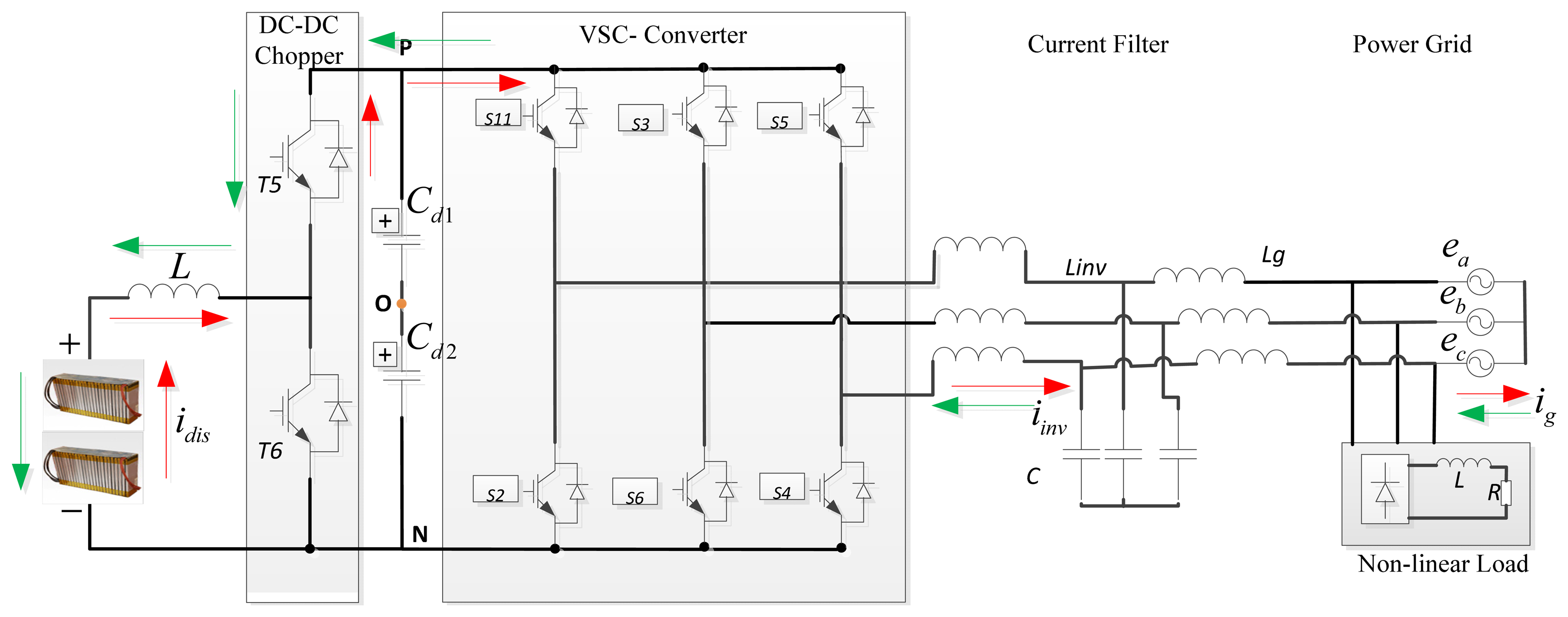
The detailed power circuit topology for the ERPBPTS is shown in Figure 1. The power circuit is composed by a non-isolating cascaded connected power converter. A direct current (DC)-DC boost chopper is responsible for wide range of constant and high accuracy charging and discharging current test, a three-level NPC voltage source converter (VSC) is used for energy recovery. An LCL-type current filter is used as an interface between the power converter and the alternating current (AC)-grid. Large value and volume of DC-link capacitors have to be used to maintain DC-link voltage constant. Discharging energy is temporarily stored in the DC-link capacitors. Therefore, the system is decoupled, which means that the two cascaded power converters could be controlled independently. Compared with conventional ERPABPTS, which use a step-down fundamental-frequency transformer as the interface, the proposed power circuit topology has much smaller volume and higher energy recovery efficiency. A non-linear load which is commonly used in the factory at the grid-side is also shown in Figure 1.
It is needed to note that in many circumstances a non-linear load (such as a diode-based rectifier) might exist at the point of common coupling (PCC), thus, the power grid will be influenced greatly, by factors such as line heat loss, noise, etc. Some of the low power instruments may even malfunction. Therefore, a multi-functional ERPABPTS which can perform reactive compensation, energy recovery and high resolution battery pack test is greatly needed.
2.2. Operation Principle of ERPABPTS
The operation principle of the ERPABPTS can be described as when performing discharging current test experiments, the DC-DC converter functions as a boost chopper, T6 switches ON and OFF with pulse width modulation (PWM). High accuracy discharging current is obtained via the bypass diode of T5, which gives rise of the DC-link capacitor voltage. Without being properly controlled, the power transistors can be damaged by high-voltage break down. Integrating the energy of DC-link capacitors to the AC-grid is a way to solve this problem. In this paper, the temporary energy is released to the power grid through a VSC. Energy balanced control between DC-DC and DC-AC converter is the most important issue for implementation. In this way, the discharging energy can be recovered effectively, which, at the same, can realize high resolution discharging current tests. Current filter, over-current protection devices, and fast-acting fuses are also used for protection. Whenever a non-linear load exists on the grid-side, the reactive power component is automatically detected and compensated by the power converter, which can be regarded as a unified grid-connected inverter and an APF.
In the following sections, we will first elaborate the operation principle of a DC-DC converter for ERPABPTS, then, a compensation control strategy considering the non-linear load will be analyzed.
3. Charge and Discharge Control of the DC-DC Chopper for EPABPTS
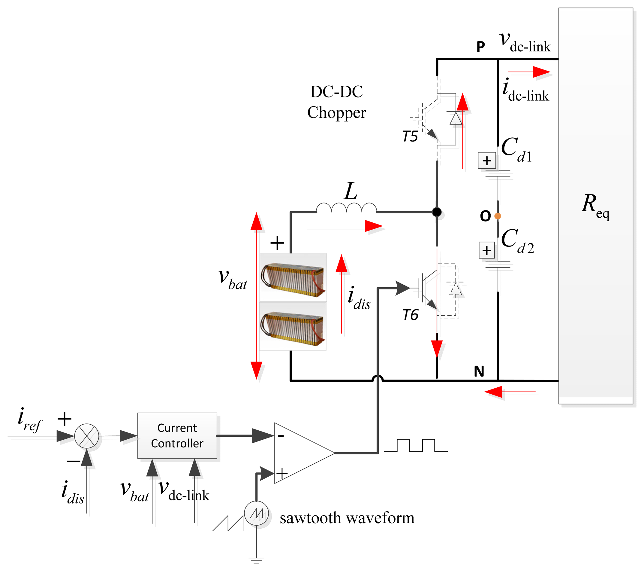
In the combined system, the DC-DC converter regulates the discharging current of the PBP, as a testing system, wide-range, high-resolution discharging and charging currents with fast response and minimum steady state error are the basic requirements. This function is used for mimicking the instantaneous startup and driving process in EVs. To improve the dynamic response, and decrease the steady-state error of the DC-DC power converter, an optimal non-linear controller and the topology of discharging part for battery pack were proposed in Figure 2, in which, iref is the reference discharging current, id is the feedback discharging current, vbat and vDC-link are terminal voltage of power accumulator battery pack and DC-link capacitors, respectively. L is the inductance for boosting. The small signal average model, stability of DC-DC boost chopper, and its corresponding non-linear digital current controller in continuous current mode (CCM) have been illustrated in [16–18] and implemented in our previous work [2,19]. The experiments included high resolution internal resistance tests, and constant discharging current tests which can be a double closed loop system (an outside voltage loop and an inner side current loop), our work in this paper will concentrate on harmonic detection and reactive compensation.
4. Harmonic Detection and Compensation Control for ERPABPTS Using Instantaneous Power Theory
4.1. Harmonic Detection and Compensation Control of ERPABPTS
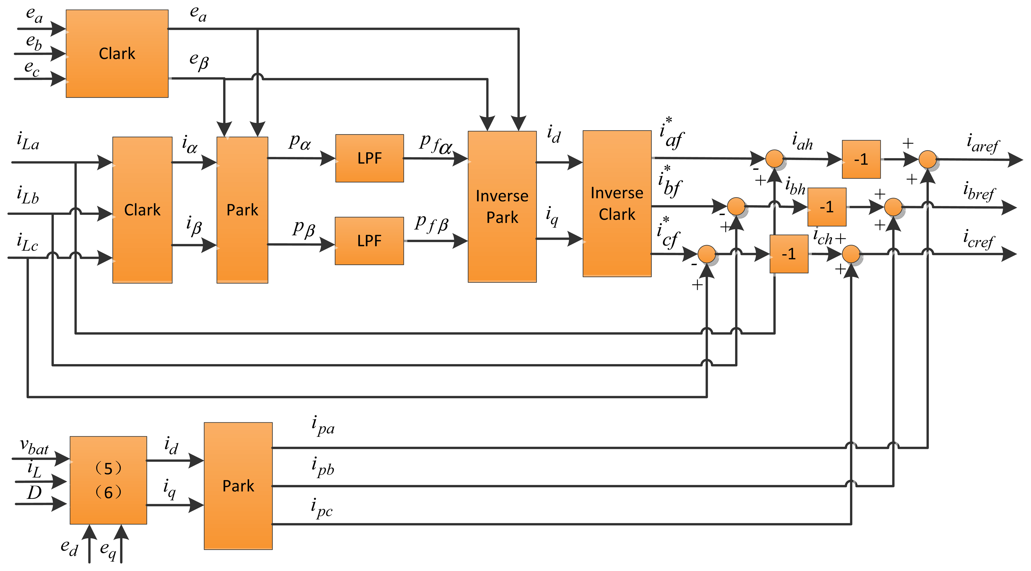
Figure 3 illustrates the proposed control diagram block scheme of the energy recovery grid-connected PABPTS. In order to obtain the harmonic current component of the non-linear load, expressions for the active and reactive power components when using instantaneous power theory are shown in Equation (1):
In Equation (1), the voltage orientation control (VOC) method is used, which means ed = |E|, eq = 0, Equation (1) can be rewritten as:
The grid-side voltage transformation block is used to acquire the equivalent voltage under synchronous rotation coordinates. Similarly, the load current transformation block is adopted to obtain the equivalent current under synchronous rotation coordinates. However, Equation (2) itself contains fundamental frequency and higher-order frequency active and reactive power components. Thus, the higher-order frequency reactive power component should be distracted from total reactive power component. A low-pass-filter (LPF) is needed in this circumstance. This procedure can be explained as:
Based on Equation (4), after Clark transformation, the equivalent phase current under stationary reference frame would be:
Considering that the grid-side voltage might be unbalanced, and can be written as:
Similarly, the expression of phase voltage under stationary reference frame using the Clark transformation would be:
Combing Equation (5) with Equation (7), according to the instantaneous power theory, the active and reactive power component of the system can be concluded as:
Substituting Equations (5) and (7) into Equation (8), the instantaneous active and reactive power component would be:
Thus, active and reactive power component at fundamental frequency would be:
Since the peak value of grid-voltage , the fundamental frequency phase current derived by using the inverse Clark transformation would be:
According to Equation (11), the higher-order phase current (iah, ibh and ich) needs to be compensated, and can be deduced by:
In Figure 3, ea, eb and ec are the phase voltage of the AC-grid, respectively. eα and eβ are the grid-voltage under stationary reference frame. iLa, iLb and iLc are the phase current of the non-linear load. The three-phase currents are firstly transformed into two-phase stationary reference frame, and then are changed into two-phase synchronous rotating reference frame to get DC-current component (iLd and iLq). According to the instantaneous power theory, active and reactive power component (pα and qβ) under stationary reference frame can be acquired. After being filtered by the designed band-pass filter, the DC-current active and reactive power component (pDC and qDC) under synchronous reference frame are derived. The reactive and harmonic power component can be obtained by subtracting pα and qβ from pDC and qDC.
4.3. Band-Pass Butterworth Power Filter Design
In order to acquire the higher order active and reactive power component, two second-order band-pass butt-worth filters are designed in this paper. Since the fundamental frequency of the grid is 50 Hz, hence, the center-frequency is chosen to be 50 Hz, the passing-band frequency is set to be 20 Hz, by using sptools block in Matlab, the continuous time transfer function of the filter can be designed as:
Sampling time is chosen as Ts = 5 μs, then, the discrete-time transfer function of the filter in Equation (14) would be:
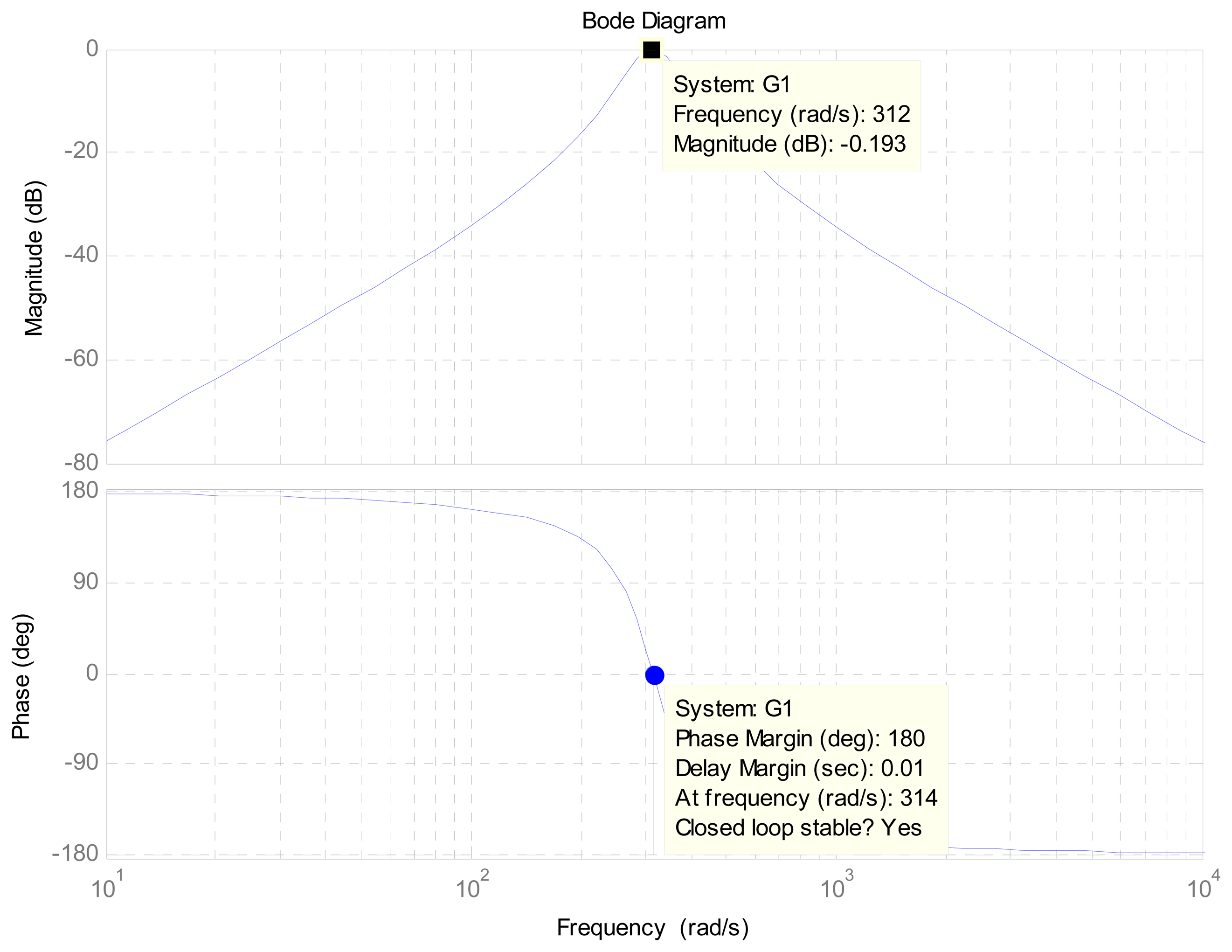
Based on Equation (15), the Bode diagram of the designed band-pass filter would be derived.
From Figure 4, we can see that the magnitude is 0.193 dB at the fundamental frequency 50 Hz (321 rad/s), the delay margin is 0.01 sec at (314 rad/s), and the magnitude has a big attenuation near the center frequency point, phase delay at the fundamental frequency is close to zero. As a result, the designed filter could satisfy our requirements.
4. Simulation Verification
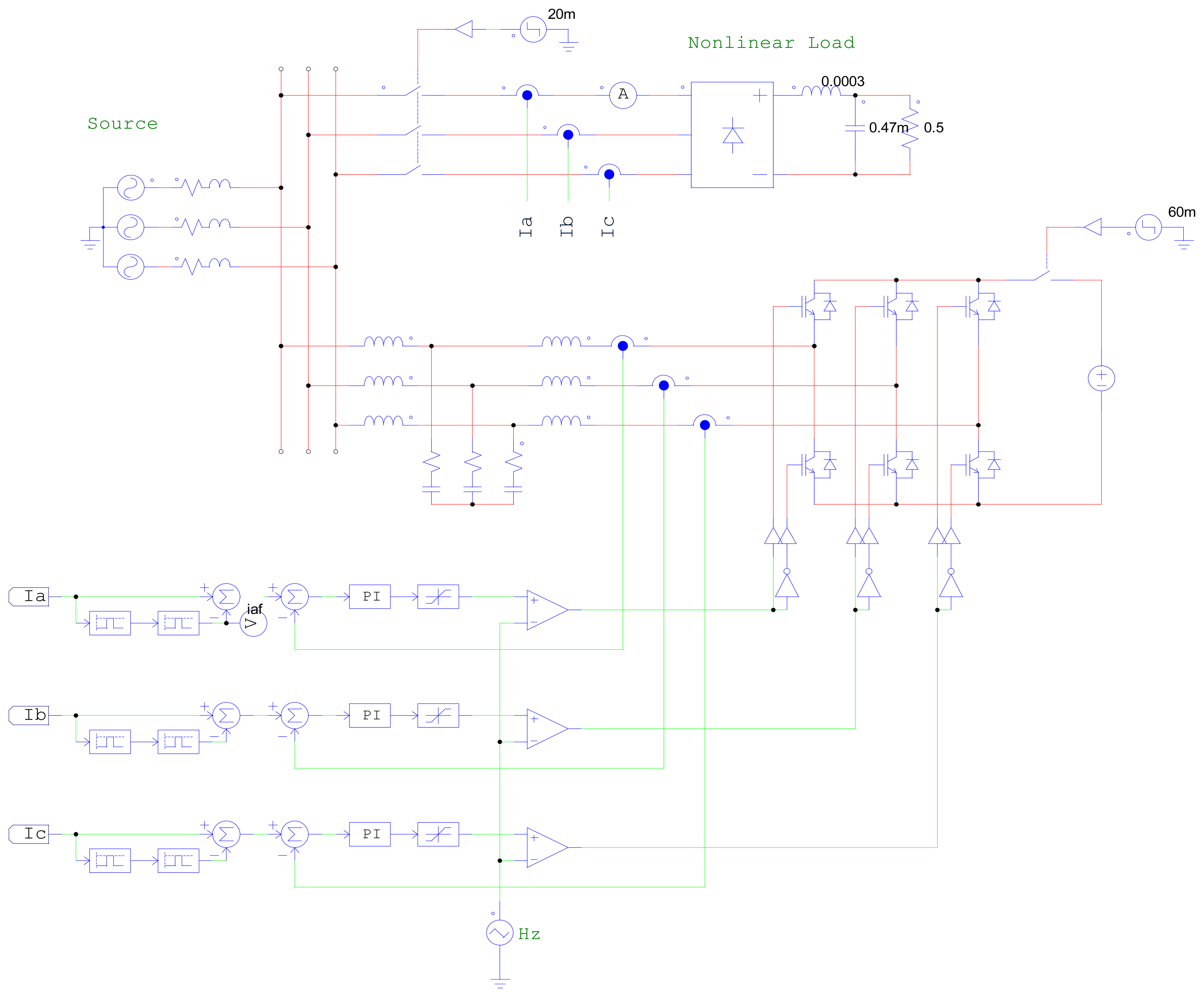
To describe and verify the validity of the proposed scheme, simulation verifications are carried out. For this purpose this work is implemented by co-simulation of Matlab/Simulink and Powersim 9.0. Powersim has the advantages of fast computation and convergence capability, and is considered as a professional power electronics simulation software. A simcoupler block is set up for the dynamic data exchange between the two environments. The schematic diagram of the proposed control technique in a distribution grid are shown in Figure 5, which contains a full-bridge diode-based rectifier with a resistance and a capacitance in parallel, and an inductance load at the DC-link. Parameters of the diode-based full bridge rectifier can be referenced in Table 1.
The following steps are performed to validate the performance of the unified ERPABPTS:
- (1)
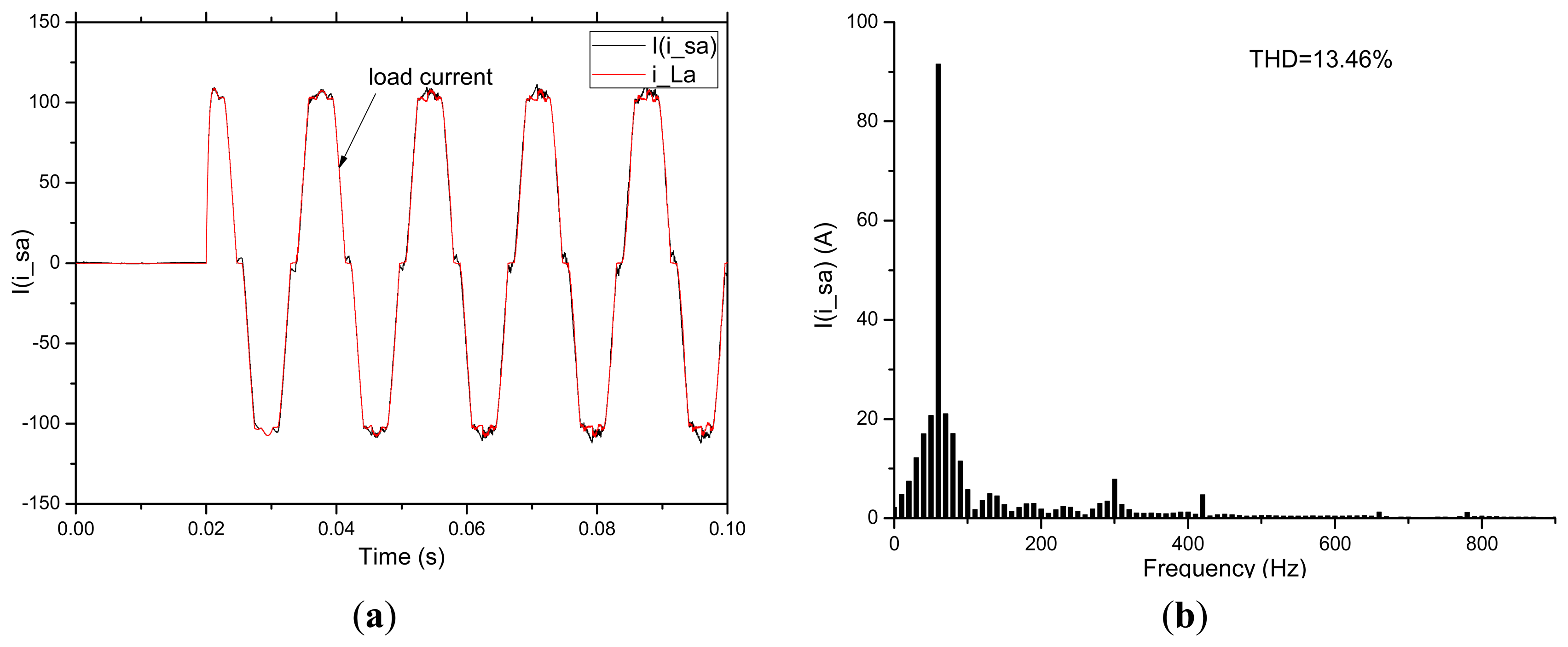
Without compensation, the non-linear load is only powered by the AC-grid. If without active current component injection, the compensation current keeps track of the harmonic current. The phase current of the non-linear load and the AC-grid are shown in Figure 6a,b. It can be clearly seen that the load current is distorted and the total harmonic of the phase current on the load is 13.46%. From Figure 6b, we know that the fifth order and seventh order harmonic current exist in the loads. The harmonic current are 10 A at fifth order and 5 A at seventh order, respectively.
- (2)
To compare the performance of the proposed scheme and conventional scheme, simulation results for the non-linear load with and without reactive compensation and harmonic detection are illustrated, firstly. Then, by using the proposed fourth-order low-pass Butterworth filter with sampling time Ts = 20 μs, cut-off frequency fc = 55 Hz, the proposed reactive compensation and harmonic suppression scheme are provided. The parameters of the proportional-integral (PI) current controller in Figure 5 are set as: kp = 2, time constant: T = 0.0001. Transfer function of the current controller is:
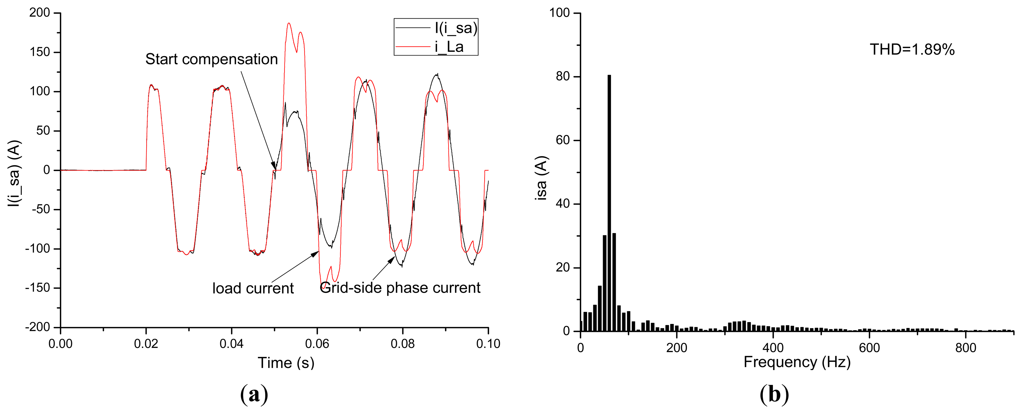
Figure 7a gives the time response of the phase-current in the non-linear load before and after integration of the ERPABPTS into the power grid without injecting the discharging current. An LCL-type filter is adopted to acquire high quality grid-connected current. Compared with the L- and LC-type filters, it has much smaller volume and current ripple, yet it brings the problems of resonance; hence, a passive damping resistance of 0.1 Ω is used in this paper. Compensation point is started at t = 50 ms, from Figure 7b, the grid side phase-current after compensation becomes more sinusoidal, and its total harmonic distortion (THD) reduced from 13.46% to 1.89%, compared with Figure 7b, the current amplitudes of the fifth-order and seventh-order are counteracted. Moreover, the current amplitude at fundamental frequency changes from 85 A to 80 A.
- (3)
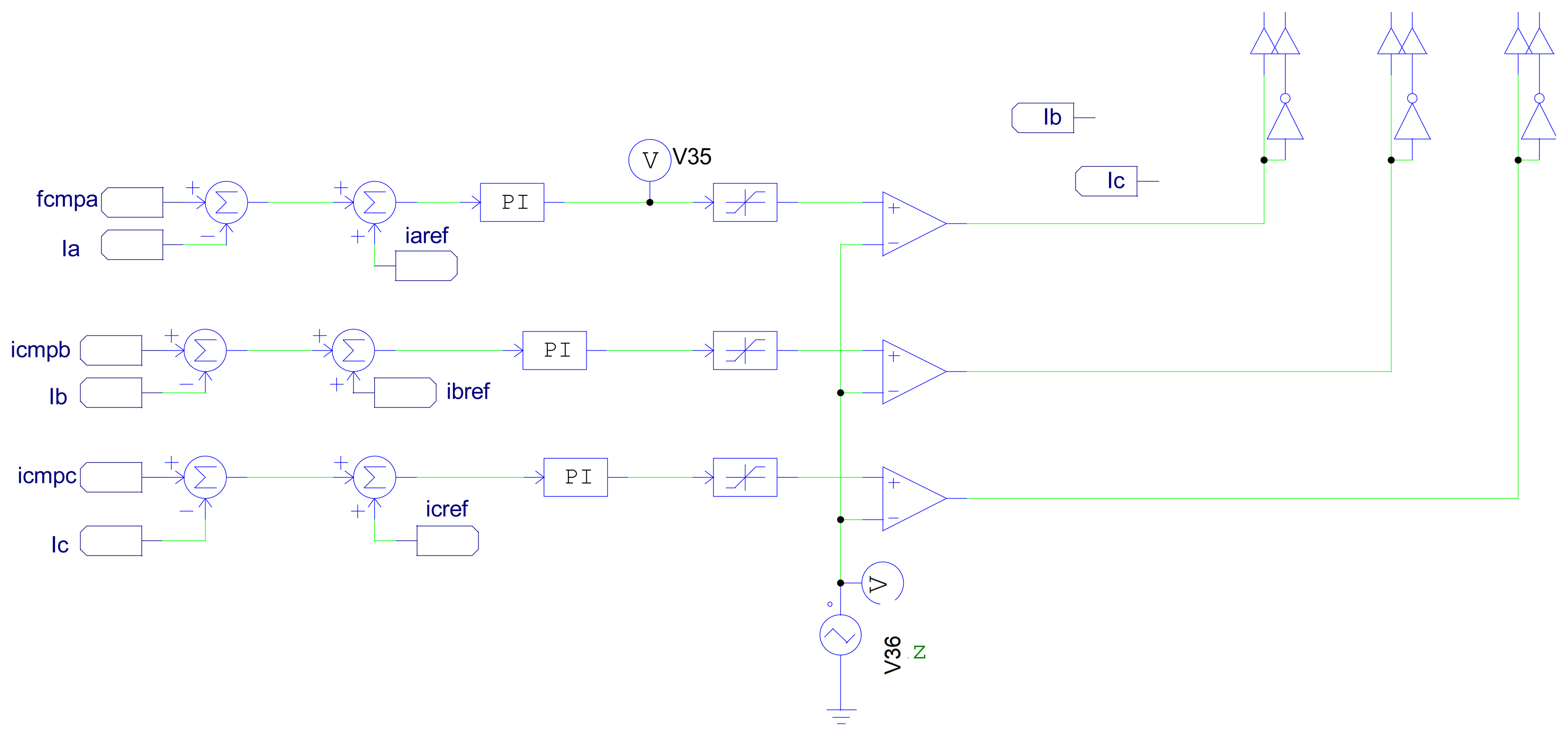
In terms of energy recovery, the energy discharged from the battery pack should be recovered to the power grid. Thus, based on the simulation work done in Step 2, active current component should be injected for modulation, which is demonstrated in Figure 8, where iaref, ibref and icref are the additional currents needed to be recovered to the power grid.
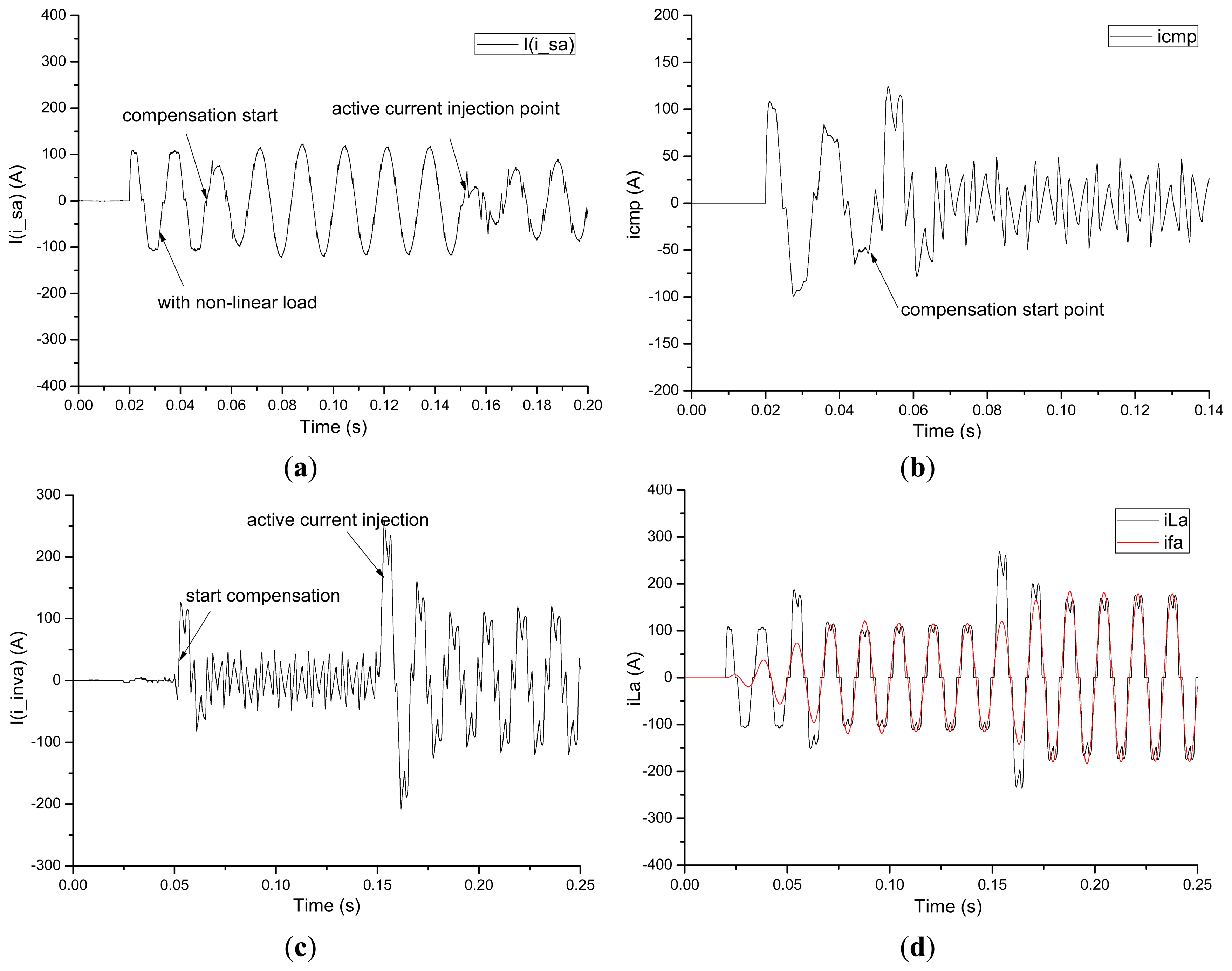
Figure 9a illustrates the time response of the grid-side phase current without compensation, with compensation and with reactive compensation. It can be seen that the THD of the grid current is 13.46% before compensation and 1.89% after compensation. From Figure 9a, we can see that when an active current component iq is given by 100 A at 150 ms, the grid-side current amplitude reduced from 117 A to 88 A, which means that the additional current 29 A is used to compensate the reactive and harmonic current. Figure 9b shows the time response of the compensation current (icmp), which is derived by the difference between the load current (iLa) and fundamental frequency current (ifa), which is calculated by using the proposed fourth-order filter. From Figure 9b, we can see that when the three-phase voltage source inverter starts compensation at t = 50 ms, the phase current of power source becomes highly sinusoidal, and has a THD of 1.89%. In Figure 9c, when t = 150 ms, the additional active current component iaref, ibref and icref are added before PI controller in Figure 9. The VSC starts to inject active current to the AC-grid, the active current (iaref, ibref and icref) reference is determined by DC-link voltage to maintain constant. Hence, a unity power factor control scheme with reactive compensation is established. Figure 9d gives the time response of the phase-current in the non-linear load and the filtered current using the designed fourth-order Butterworth filter. It can be obviously seen that after being filtered by the designed band-pass filter, the fundamental frequency current of the non-linear load can be successfully extracted from the load current iLa.
5. Experimental Section
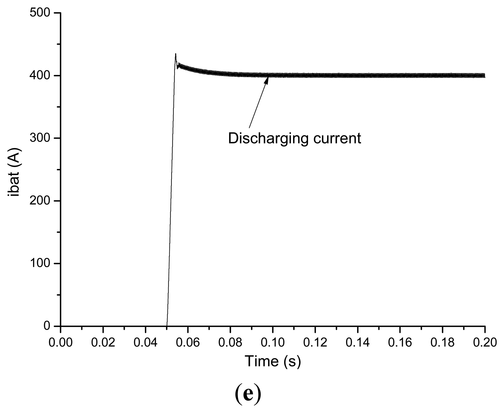
A multi-functional inverter, which is used for a grid-connected energy recovery Li-ion type power battery testing system experimental platform, is set up to verify the proposed design. A microcontroller (DSP-TMS320LF2808, Texas Instrument, Dallas, TX, USA) is used for fast computation and implementation. The hardware configuration setup of the power circuit is shown in Figure 10a. The Li-ion battery used for experiment is presented in Figure 10b. Parameters of the power transistor, inverter-side filter, DC-DC converter and AC-DC converter are listed in Tables A1 and A2 in the Appendix. The composite control scheme can be referenced in the simulation section. Figure 10c gives the phase-current of the power-grid before and after connecting the non-linear load with and without reactive compensation. Similar with the simulation results, after reactive compensation, the phase-current of the power-grid becomes more sinusoidal. Thus, a unified multi-functional ERPABPTS is established, which is more applicable for a battery test. Figure 10d gives the waveform of the DC-link current, which is generated due to the DC-DC converter in discharging mode, a step reference current of 400 A is given at 50 ms, from Figure 10d, we may know that after a slight current overshot with the peak value of 420 A, the instantaneous peak current is caused due to the existence of DC-link capacitance. The feedback current keeps track of the reference current very well, hence, requirements on high resolution, high power output and wide range of voltage and current test experiment is realized, which demonstrated the correctness and utility of the proposed scheme.
6. Conclusions
A unified harmonic suppression, reactive compensation and energy recovery power accumulator battery pack test system is proposed. The topology and control strategy proposed in this paper can eliminate harmonics generated by the nearby non-linear loads and realize reactive compensation. The proposed reactive power and harmonic detection scheme can effectively detect the fundamental frequency active and reactive power components. Compared with a conventional battery pack test system, the unified control scheme improves and extends the performance of the combined system. A TMS320LF2808-based DSP controller using the proposed method has been developed, and is implemented in a 175-kW prototype in the laboratory. The results show that the THD is reduced from 13.46% to 1.89% in grid-connected condition, which demonstrates the good performance for harmonic elimination and the reactive compensation scheme proposed in this paper.
Since many ERPABPTS sharing the same AC-grid are used in battery companies, it is suggested that the future work might focus on ways of solving coordination control and energy management problems existing in multi-ERPABPTS systems.
Acknowledgments
This work was simultaneously supported by the Fundamental Research Funds for the Central Universities of China (No. ZYGX2012J095), China Postdoctoral Science Foundation Funded Project (2013M542266), and also supported by the National Research Foundation of Korea (NRF) grant funded by the Korea government (MEST) (No. 2013-009458) and (No. 2013-068127). The authors would like to thank all the reviewers for their advices and suggestions on improving this paper.
Conflicts of Interest
The authors declare no conflict of interest.
Appendix

| Components | Part name/manufacturer | Rating values |
|---|---|---|
| IGBT | SKM400GB128D/Semikron (Berlin, Germany) | 1,200 V–400 A |
| Fast recovery diode | SKKD75F12/Semikron | 1,200 V–75 A |
| Capacitor | YDK Technologies Company (Tokyo, Japan) | 450 V–5,000 μF |
| Elements | Parameters | Values |
|---|---|---|
| PBP | Battery terminal voltage Vbat | 240 V |
| Battery type | Li-ion | |
| AC Power grid | Grid voltage (line to line rms) Vg | 380 V |
| Line frequency fn | 50 Hz | |
| Grid inductance Lgrid | 1 mH | |
| LCL Filter | Inverter side inductor Linv | 1 mH |
| Grid side inductor Lg | 0.5 mH | |
| Filter capacitance C | 4.7 μF | |
| DC-DC Converter | Nominal power | 175 kW |
| Inductor for boost chopping L | 4 mH | |
| Switching frequency fs | 5,000 Hz | |
| Dead time td | 2 μs | |
| DC-AC Converter | Nominal power Pe | 175 kW |
| Two series DC-link capacitor CDC | 16,000 μF | |
| Initial DC-link capacitor voltage Vc0 | 500 V | |
| DC-link voltage reference VDC_ref | 900 V | |
| IGBT switching frequency finv | 2,000 Hz | |
| Dead time td | 2 μs | |
References
- Zhang, L.; Kang, W.; Jia, L.; Zhao, M.; Xu, R. Control of bidirectional current source SVPWM converter in the power accumulator battery testing system. Proceedings of the Asia-Pacific Power and Energy Engineering Conference (APPEEC), Chengdu, Sichuan, China, 28–31 March 2010; pp. 1–4.
- Long, B.; Xian, Z.; Lim, S.T.; Chong, K.T. Design of energy recovery power battery pack testing system. Int. Rev. Electr. Eng. 2012, 7, 4672–4683. [Google Scholar]
- Long, B.; Chong, K.T. Modeling and direct power control of energy recovery power battery testing system under charging mode—A new approach. Int. Rev. Electr. Eng. 2012, 7, 5993–6004. [Google Scholar]
- Long, B.; Lim, D.; Chong, K.T. Design of transformer-less high power output battery testing system using three-level NPC inverter. Int. Rev. Electr. Eng. 2012, 7, 6104–6115. [Google Scholar]
- Long, B.; Chong, K.T. Parameter design and power flow control of energy recovery power accumulator battery pack testing system. J. Electr. Eng. Technol. 2013, 8, 742–753. [Google Scholar]
- Zaveri, N.; Chudasama, A. Control strategies for harmonic mitigation and power factor correction using shunt active filter under various source voltage conditions. Int. J. Electr. Power Energy Syst. 2012, 42, 661–671. [Google Scholar]
- Asiminciaei, L.; Blaabjerg, F.; Hansen, S. Detection is key—Harmonic detection methods for active power filter applications. IEEE Ind. Appl. Mag. 2007, 13, 22–33. [Google Scholar]
- McGrath, B.P.; Holmes, D.G.; Galloway, J.J.H. Power converter line synchronization using a discrete Fourier transform (DFT) based on a variable sample rate. IEEE Trans. Power Electron. 2005, 20, 877–884. [Google Scholar]
- Gonzalez, S.A.; Garcia-Retegui, R.; Benedetti, M. Harmonic computation technique suitable for active power filters. IEEE Trans. Ind. Electron. 2007, 54, 2791–2796. [Google Scholar]
- Jacobsen, E.; Lyons, R. The sliding DFT. IEEE Signal Process. Mag. 2003, 20, 74–80. [Google Scholar]
- Jeong, H.-G.; Lee, J.-H.; Lee, K.-B. A 2nd order harmonic compensation method for wind power system using a PR controller. J. Electr. Eng. Technol. 2013, 8, 507–515. [Google Scholar]
- Yuan, X.M.; Merk, W.; Stemmler, H.; Allmeling, J. Stationary-frame generalized integrators for current control of active power filters with zero steady-state error for current harmonics of concern under unbalanced and distorted operating conditions. IEEE Trans. Ind. Appl. 2002, 38, 523–532. [Google Scholar]
- Qian, L.; Cartes, D.; Li, H. Experimental verification and comparison of MAFC method and D-Q method for selective harmonic detection. Proceedings of the 32nd Annual Conference on IEEE Industrial Electronics, IECON, Paris, France, 6–10 November 2006; pp. 25–30.
- Cirrincione, M.; Pucci, M.; Vitale, G.; Miraoui, A. Current harmonic compensation by a single-phase shunt active power filter controlled by adaptive neural filtering. IEEE Trans. Ind. Electron. 2009, 56, 3128–3143. [Google Scholar]
- Wang, Y.F.; Li, Y.W. Three-phase cascaded delayed signal cancellation PLL for fast selective harmonic detection. IEEE Trans. Ind. Electron. 2013, 60, 1452–1463. [Google Scholar]
- Jung, Y.S. Small-signal model-based design of digital current-mode control. IEE Proc. Electr. Power Appl. 2005, 152, 871–877. [Google Scholar]
- Al-Mothafar, M.R.D.; Hammad, K.A. Small-signal modelling of peak current-mode controlled buck-derived circuits. IEE Proc. Electr. Power Appl. 1999, 146, 607–619. [Google Scholar]
- Veerachary, M. Modelling and analysis of cascade step-down converters. IEE Proc. Electr. Power Appl. 2005, 152, 41–50. [Google Scholar]
- Chan, C.Y. A nonlinear control for DC-DC power converters. IEEE Trans. Power Electron. 2007, 22, 216–222. [Google Scholar]


| Component | Part name | Values |
|---|---|---|
| Non-linear load | Inductance | 0.3 mH |
| Capacitance | 470 μF | |
| Resitance | 0.5 Ω | |
| AC-grid | Lineto line voltage | 110 V |
| Frequency | 60 Hz | |
| Internal inductance | 0.1 mH | |
| Internal resistance | 0.5 Ω | |
| LCL filter | Grid side inductance | 0.5 mH |
| Capacitance | 2 μF | |
| Reactive damping resistance in series | 0.1 Ω | |
| Inverter side inductance | 2 mH | |
© 2014 by the authors; licensee MDPI, Basel, Switzerland. This article is an open access article distributed under the terms and conditions of the Creative Commons Attribution license ( http://creativecommons.org/licenses/by/3.0/).
Share and Cite
Long, B.; Ryu, J.H.; Lim, S.T.; Chong, K.T. Design and Control of a Multi-Functional Energy Recovery Power Accumulator Battery Pack Testing System for Electric Vehicles. Energies 2014, 7, 1376-1392. https://doi.org/10.3390/en7031376
Long B, Ryu JH, Lim ST, Chong KT. Design and Control of a Multi-Functional Energy Recovery Power Accumulator Battery Pack Testing System for Electric Vehicles. Energies. 2014; 7(3):1376-1392. https://doi.org/10.3390/en7031376
Chicago/Turabian StyleLong, Bo, Ji Hyoung Ryu, Shin Teak Lim, and Kil To Chong. 2014. "Design and Control of a Multi-Functional Energy Recovery Power Accumulator Battery Pack Testing System for Electric Vehicles" Energies 7, no. 3: 1376-1392. https://doi.org/10.3390/en7031376