Research on a 20-Slot/22-Pole Five-Phase Fault-Tolerant PMSM Used for Four-Wheel-Drive Electric Vehicles

Abstract
: This paper presents a five-phase fault-tolerant permanent-magnet synchronous machine (PMSM) used for electric vehicles. In multiphase fault-tolerant PMSMs equipped with fractional-slot concentrated windings, excessive magneto-motive force (MMF) harmonics can lead to thermal demagnetization of the permanent magnets (PMs). In order to reduce the lower-order harmonics, the origins of the 2-pole harmonic in conventional winding configurations are investigated, and an unequal-turn winding configuration is applied to cancel the lower-order harmonics. The main electromagnetic performances of the unequal-turn winding configuration are investigated and compared with conventional winding topologies. Based on the principle of maintaining constant instantaneous power, the fault-tolerant control strategies for open-circuits of up to two phases are developed. All of the investigations are verified by finite element analysis (FEA) results.1. Introduction
High fault-tolerant capability and high reliability are increasingly required in various applications. Owing to its high power density and high efficiency, a multiphase fault-tolerant permanent-magnet synchronous machine (PMSM) is often considered an excellent candidate for safety critical applications such as electric vehicles (EVs), marine propulsion and aerospace. In order to minimize the effect of fault phases on the other healthy phases, multiphase fault-tolerant PMSMs are designed to have low mutual inductances between different phases, and each phase of the machine is driven by a separate H-bridge converter. A large phase inductance enables the terminal short-circuit current to be limited below its rated value. The above design features ensure the machine can be operated continuously under fault conditions.
In the past decades, PMSMs equipped with fractional-slot concentrated windings (FSCWs) have increasingly been used in EV applications [1–7]. With such windings the concentrated coils are wound either on adjacent or alternate teeth, which reduces the end winding length. Furthermore, a significant reduction of the copper loss is achieved, and the machine efficiency is improved [8–10]. Compared with traditional distributed windings, FSCW have low mutual inductances between phases, which meet the magnetic isolation demands of phase windings for multiphase fault-tolerant PMSM [11–14]. But FSCW also introduces many lower and higher order space harmonics, which have negative effects on machine performance, including localized saturation, eddy current losses in permanent magnets (PMs), possible resonance and noise, etc. The impacts of slot/pole combinations and magneto-motive force (MMF) harmonics on rotor eddy current losses in concentrated winding PM machines were analyzed by Aslan and Semail and Bianchi and Fornasiero, respectively [15–18]. By studying the interaction between MMF harmonics wavelengths and PM pole dimensions, a general analytical model of PM eddy-current losses is developed for comparison of multiphase PM machines [19,20]. The influence of post-fault control strategy and winding configuration on rotor losses is evaluated by both an analytical time-stepping model and a time harmonic current sheet method [21]. The impacts of slot harmonic and the number of phases on rotor losses in fractional-slot PM machines are investigated in [22]. Due to irregular MMF distribution, FSCW introduces unbalanced radial forces, and this causes considerable vibration and noise. The impacts of slot/pole combination choices on unbalanced radial forces and vibration modes are analyzed in [15]. The radial force density harmonics and vibration characteristics of fractional-slot PM machines are investigated in [23–26], and since FSCW machines are more susceptible to low frequency resonant vibrations, hence, for EV applications where a silent and smooth operation is required, the characteristics of the magnetic forces should be considered during the machine design process.
By reducing the lower-order MMF harmonics of FSCWs, machine performance can be improved to a certain extent, and several technical solutions have been developed to reduce or even cancel lower-order harmonics [27–29]. By shifting specific windings with a certain number of slots, the lower-order harmonics can be reduced a lot, but the working harmonic is also decreased, which is undesirable in the reduction process of lower-order harmonics. Besides, both lower- and higher-order harmonics can be reduced simultaneously by doubling stator slots and adding another set of windings [30]. Due to the overlapped winding structure, the mutual inductances are larger than those of concentrated winding topologies, and they are not suitable for fault-tolerant PMSMs. Aiming to improve machine efficiency, a winding configuration featured with different turns per coil side is also presented in [31], but the fault-tolerance performance of the proposed windings is not investigated, and for such kind of windings, further research focusing on their application in multiphase fault-tolerant PMSM and sub-harmonic cancelling principle are still needed.
For four-wheel direct-drive EVs, low torque ripple enables low vibration and high driving comfort, but machine failures including open-circuit faults and short-circuit faults result in loss of torque or dangerous torque disturbance, which is detrimental to passenger safety, so continuous and smooth operation after faults is very important. In this paper, a five-phase in-wheel outer-rotor PMSM which shows advantages in high fault-tolerant ability and low torque ripple is proposed for high-reliability four-wheel-drive EVs. And the investigated multiphase PMSM adopts FSCW to obtain satisfactory fault-tolerant performance and low torque ripple, and these features make the machine quite competitive for four-wheel-drive EVs.
For PMSMs equipped with FSCWs, the MMF harmonics cause eddy currents in PMs, and this leads to a temperature rise. In order to protect PMs and improve machine reliability and efficiency, an unequal-turn winding configuration featuring different turns per coil side is applied to the investigated five-phase PMSM.
Due to the additional degrees of freedom, the five-phase PMSM has better reliability compared with conventional three-phase PMSM. A control strategy that enables post-fault operation of a five-phase PMSM is introduced. Based on the principle of maintaining constant instantaneous power, the phase currents for healthy phase windings are obtained by minimizing a cost function of copper loss. Under this scheme, the five-phase PMSM enables continuous and smooth operation with open-circuit faults of up to two phases. The fault-tolerant control strategy is verified by FEA.
2. Machine Specification and Slot/Pole Combinations Choice
In general, there are two different topologies for four-wheel-drive EVs: high-speed drive incorporating an additional gear box or low-speed direct drive. Table 1 summarizes some typical specifications of the electric drive systems, i.e., the commercial Prius and Protean Electric drive systems [32–34], the radial-flux PM hub machine developed by Rix and Kamper [35], and the direct-drive machine investigated in this paper.
The 2004 Prius uses a high-speed machine with an additional gear box, so the number of poles is relatively low. The Protean Electric system and Radial-flux PM hub machine are direct-drive systems, using a high number of poles. In this paper, a four-wheel direct-drive scheme is used, so the number of poles is relatively high. Considering both fault-tolerant capability and power density, the slot/pole combinations for five-phase fault-tolerant PMSMs which satisfy 2p = Q ± 2 (where Q is number of slots, and 2p is number of poles) are proposed [36]. The rotor losses on such slot/pole combinations are thoroughly investigated in [15,19], and the analysis results indicate that in comparison with the low pole-number choice (2p = Q − 2), the high pole-number choice (2p = Q + 2) leads to higher rotor losses, which will reduce the power density. However, for the direct-drive outer-rotor machine used for four-wheel-drive EVs, the space limitation is serious, and compared with a low pole-number choice, the high pole-number choice results in a very shallow rotor core back and creates a “ring” type structure, and the center of the ring can be used to house the cooling system. Under a certain space limitation, a shallow core back of outer rotor enables a relative large air gap diameter, and this will improve the machine power density. The optimization dealt with this problem would require extensive model analysis and it is not concerned in this paper. Finally, the 20-slot/22-pole winding configuration is adopted in this paper.
3. Research on 20-Slot/22-Pole Winding Topologies
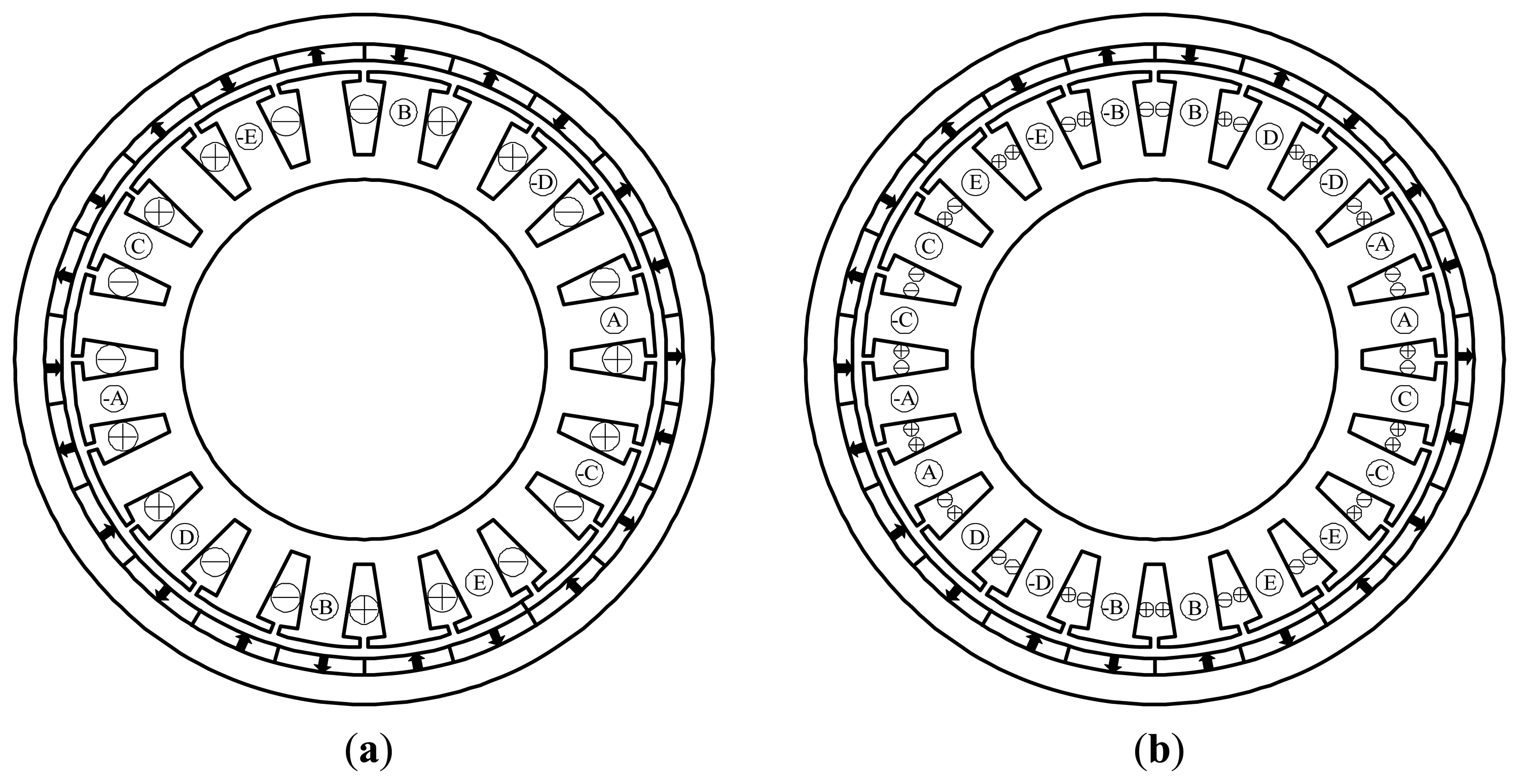
Conventionally, there are two winding topologies for the chosen slot/pole combination. One is single-layer winding configuration, and the other is double-layer winding configuration, as shown in Figure 1. For the chosen 20-slot/22-pole winding configuration, the winding factor of single-layer winding is 0.9877, which is a little higher than that of double-layer winding, i.e., 0.9755. But double-layer winding features advantages in rotor losses and mechanical balancing [15,16], combining the high-efficiency requirement of EV applications, the 20-slot/22-pole double-layer winding configuration is further investigated in this paper.
3.1. Air-Gap Flux Density (Produced by Windings) of the Conventional 20-Slot/22-Pole Winding Topology
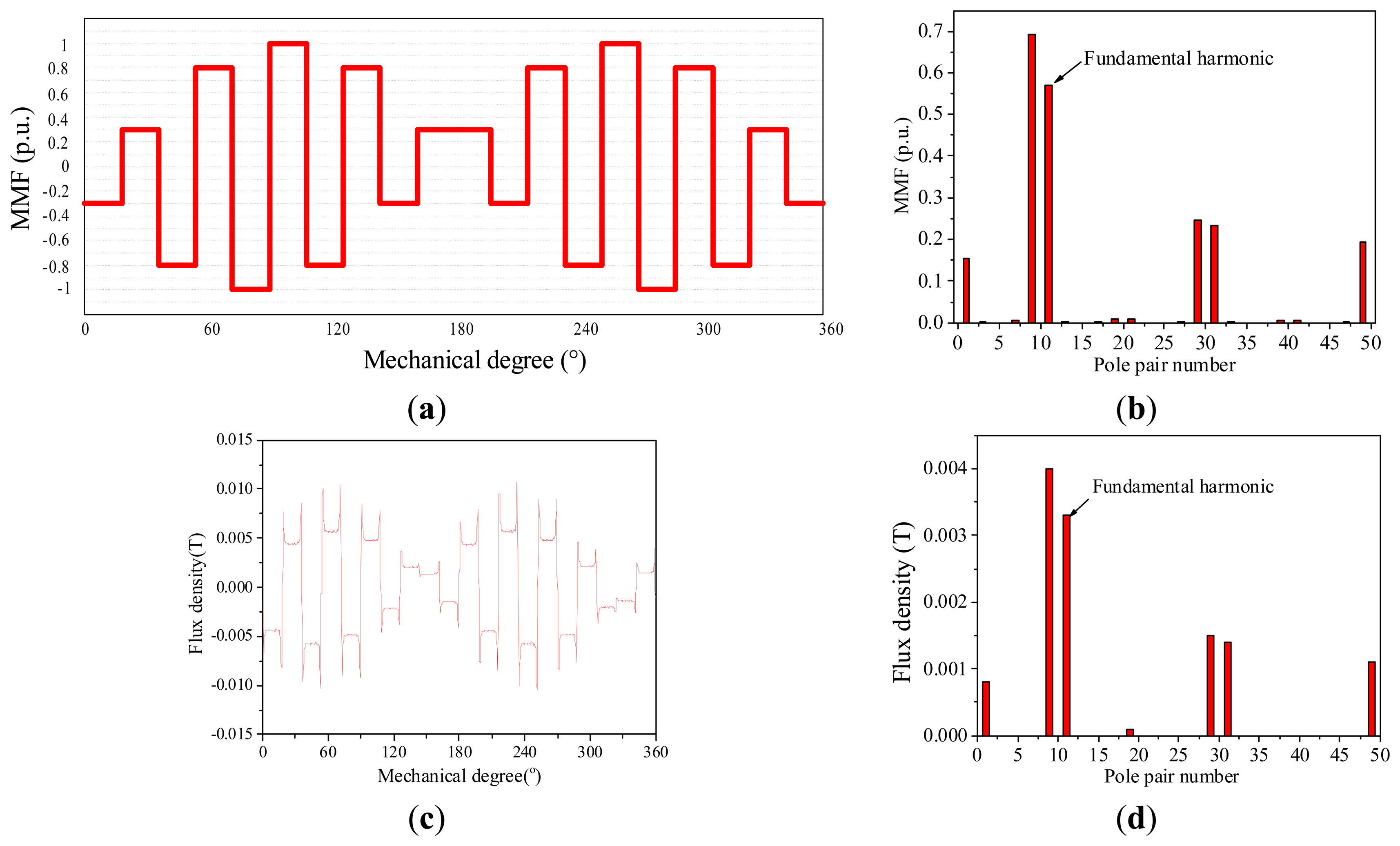
In this section, electromagnetic performances of the 20-slot/22-pole double-layer winding configurations are investigated by FEA. Aiming to focus on the analysis of armature flux density, PMs are removed from the FEA models. The MMF distribution, air-gap flux density and their corresponding harmonic analysis of the double-layer winding configuration are shown in Figure 2.
As shown in Figure 2, the MMF distribution indicates that an obvious 2-pole harmonic exists in the air gap, which is consistent with the calculated FEA results, and it verifies that the MMF analysis method is effective in the qualitative analysis process of armature flux distribution. The harmonic analysis shows that the 2-pole, 18-pole, and 22-pole space harmonics are dominant harmonics, but only the 22-pole harmonic interacts with the 22-pole PM field and generates constant torque. Generally, the armature space harmonic which interacts with the PM field and produces constant torque is named fundamental harmonic, and the space harmonics whose pole numbers are less than that of the fundamental harmonic are called sub harmonics. For the 20-slot/22-pole windings, the 22-pole space harmonic is fundamental harmonic, the 2-pole and 18-pole harmonics are sub harmonics.
The sub harmonics induce eddy current losses in the PMs, and the eddy-current losses are determined by the relative velocity (versus the fundamental harmonic) and amplitude of the harmonic. The relative velocities of the harmonics are in inverse proportion to their orders. Thus, among all of the sub harmonics, the 2-pole sub harmonic has the highest relative velocity with respect to the fundamental harmonic (eleven-fold rotating speed of the machine), and the 18-pole sub harmonic has a relative low speed but high amplitude, so both 2-pole and 18-pole sub harmonics generate considerable effect on rotor losses. In following section we focus on the investigation of the 2-pole sub harmonic.
3.2. The Origin of the 2-Pole Harmonic of the Conventional Winding Topologies
With only one phase activated, the MMF and air-gap flux density of single-layer windings are shown in Figure 3.
For the 20-slot single-layer winding configuration, there are only two coils of one phase, and they have opposite winding directions, so it is inevitable that a 2-pole harmonic exists in the air-gap MMF, and this is consistent with the FEA calculated air-gap flux density.
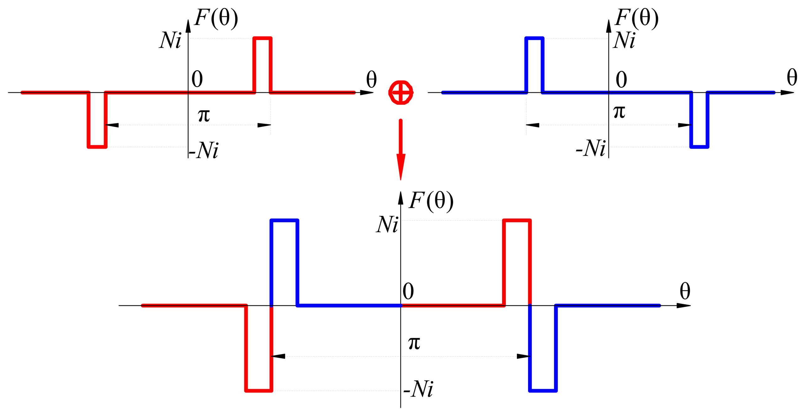
For the 20-slot double-layer winding configuration, there are four coils of one phase, the adjacent two coils have opposite winding directions, and one coil side of the adjacent two coils shares the same slot. With only one phase activated, the MMF of double-layer windings is shown in Figure 4.
From the MMF point of view, double-layer windings can be equivalently considered as superposition of two single-layer windings whose winding directions are opposite, as shown in Figure 4, so the 2-pole harmonics in the two equivalent single-layer windings will suppress each other, then the 2-pole harmonic in double-layer windings is reduced. Since the adjacent two coils are wound on different teeth, there is a certain phase shift between the two equivalent single-layer windings, so the 2-pole harmonic cannot be reduced to zero in conventional double-layer windings, which is consistent with the analysis results of Section 3.1.
3.3. The Unequal-Turn Winding Topology
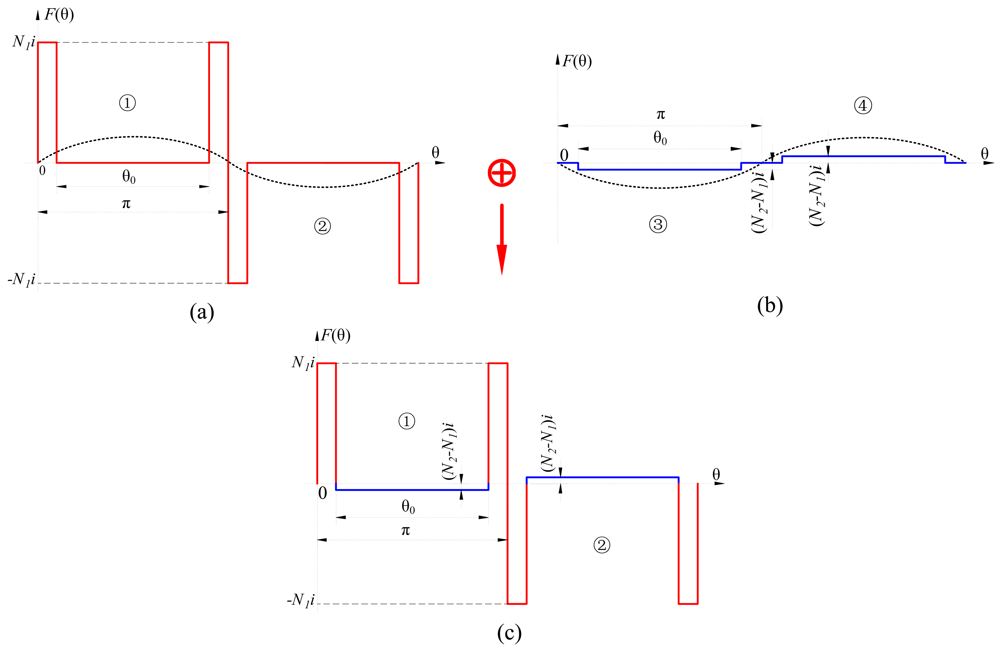
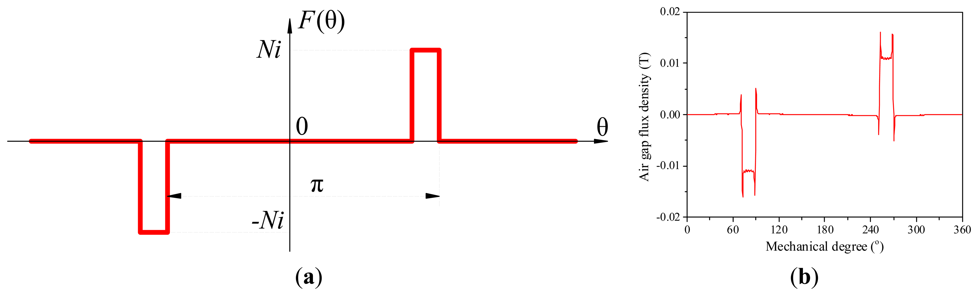
From the above analysis, we know that the 2-pole sub harmonic in conventional double-layer winding configuration cannot be reduced to zero. For the 2-pole sub harmonic, the wave crest of the 2-pole harmonic locates in the center of Area 1, and the wave trough of the 2-pole harmonic locates in the center of Area 2, as shown in Figure 5a.
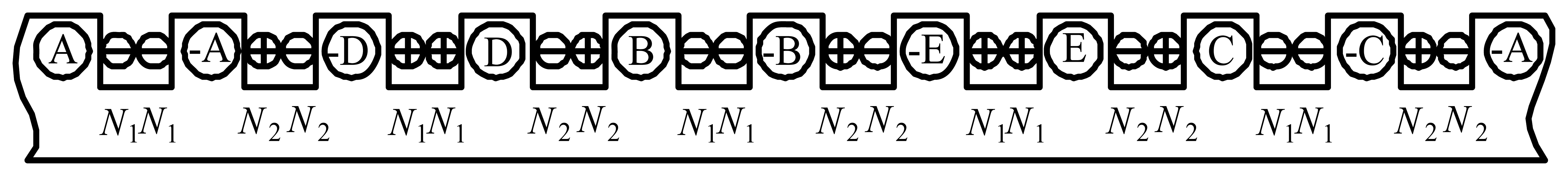
In order to reduce the 2-pole harmonic to zero, a “negative” 2-pole MMF is introduced to cancel the 2-pole sub harmonic, as shown in Figure 5b. Due to the introduced “negative” 2-pole MMF, the wave crest in Area 1 and wave trough in Area 2 can be canceled. The introduced “negative” 2-pole MMF can be realized by adopting unequal-turn winding topology, as shown in Figure 5c and Figure 6. Different from conventional winding configurations, the number of turns per coil side is different for the unequal-turn winding configuration. The manufacturing of unequal-turn winding is a little different from that of conventional winding, and the winding coils with different turns per coil side can be realized by winding only one side of the last turn. N1 donates turn number of coil sides in the slots which contain coils of the same phase, N2 donates turn number of coil sides in the slots which contain coils of different phases, and the relation between N1 and N2 is [31]:
4. Performance Comparison of the Conventional and Unequal-Turn Winding Topologies
4.1. Winding Factor of the Unequal-Turn Winding Topology
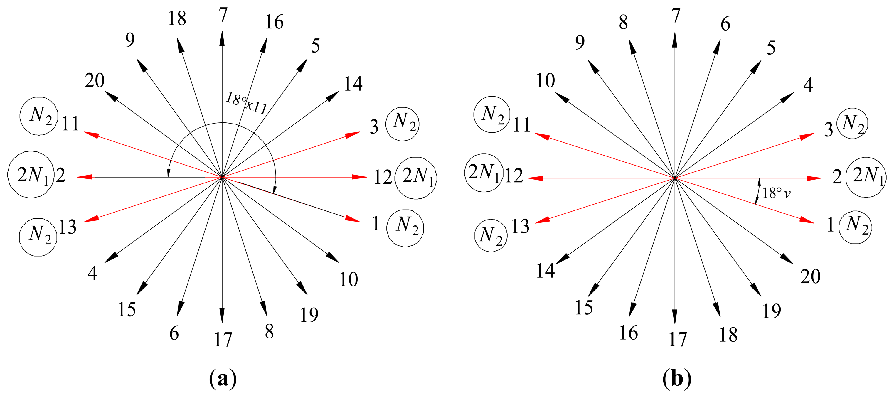
The winding factor of the unequal-turn winding topology cannot be calculated using the classic formula like the conventional winding topology. An improved slot-vector diagram is developed to calculate the winding factor of the unequal-turn windings. Slot-vector diagram represents the electromotive force (EMF) induced in the conductors of each slot, and it is useful to study the harmonics of different orders, i.e., sub harmonics, fundamental harmonic, and high-order harmonics. For the studied 20-slot/22-pole winding configuration, the slot-vector diagram is shown in Figure 7a.
The resultant phasor of the fundamental harmonic is given by the sum of the phasors 1, −2, 3, −11, 12, −13, the amplitudes of the phasors 1, 3, 11, and 13 are all N2, the amplitudes of both the phasors 2 and 12 are 2N1. Winding factor of the fundamental harmonic equals the ratio between the amplitude of the resultant phasor and the sum of amplitude of the phasors 1, 2, 3, 11, 12, and 13.
The winding factor of other harmonics can also be investigated by the slot-vector diagram. Since the winding connection has been fixed by the fundamental harmonic (as shown in Figure 7a), the resultant phasor of the v-th harmonic is given by the sum of the phasors 1, −2, 3, −11, 12 and −13, as shown in Figure 7b. Winding factors of the other harmonics equal the ratios between the amplitude of the resultant phasor and the sum of amplitudes of the phasors 1, 2, 3, 11, 12 and 13. In fact, Figure 7b is a universal slot-vector diagram for calculating winding factors of the unequal-turn winding configuration. For example, when v = 11, Figure 7b is the same as Figure 7a; when v = 1, winding factor of the 2-pole sub-harmonic can be calculated.
Then winding factor for the unequal-turn winding topology can be described as:
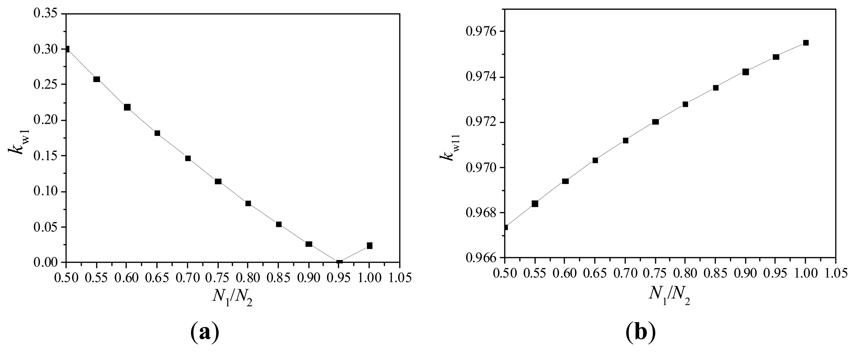
The winding factors of the 2-pole harmonic and the fundamental harmonic vary with the ratio between turns of different coil sides, as shown in Figure 8.
It is shown that the 2-pole harmonic is reduced to zero at the optimal point with N1/N2 = 0.95, and the fundamental harmonic is reduced by 0.06%. Also the relation between N1 and N2 meets Equation (1), so N1 is 19, and N2 is 20.
4.2. Comparison of the Air-Gap Flux Densities (Produced by Windings) between the Conventional and Unequal-Turn Winding Topologies
With the optimum turn ratio of different coil sides, the winding factors and amplitudes of the air-gap flux densities for the unequal-turn windings are calculated, as shown in Table 2. The winding factors and amplitudes of the air-gap flux densities for conventional winding topologies are also listed.
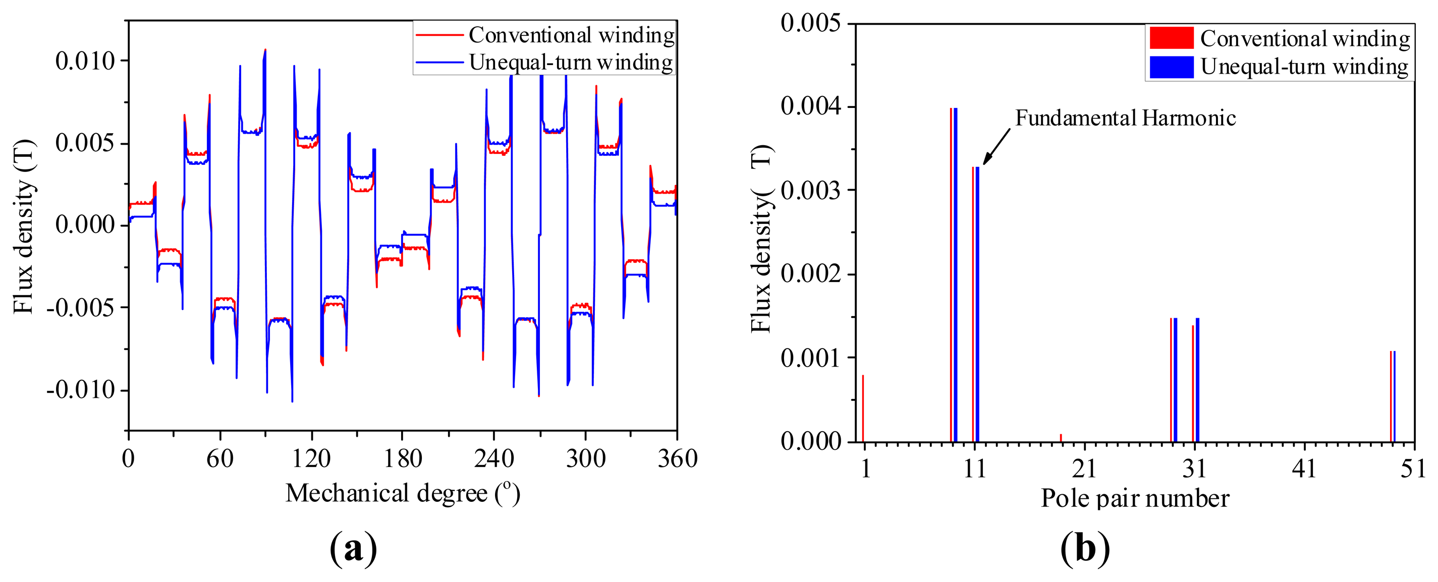
For the single-layer winding configuration, the amplitude of the 2-pole harmonic is 1.56 times of the fundamental harmonic, and for the conventional double-layer winding configuration, the 2-pole harmonic reduces to 24% of the fundamental harmonic. With the optimum turn ratio of different coil sides, the 2-pole harmonic is cancelled in the unequal-turn winding configuration. The air-gap flux densities of the conventional double-layer and unequal-turn winding configuration are compared, as shown in Figure 9. The FEA results indicate that the lower-order harmonic with 2 poles is cancelled and the fundamental harmonic nearly unchanged, which verifies the effectiveness of the unequal-turn winding configuration on reducing the 2-pole sub harmonic.
4.3. Comparison of Mutual Inductances between Conventional and Unequal-Turn Winding Topologies
For multiphase fault-tolerant PMSM, low mutual inductance between phases is a key requirement. In order to compare the mutual inductances of the unequal-turn winding configuration with those of the conventional winding topologies, the static magnetic fields of the conventional and unequal-turn winding configurations with PMs removed and only one phase windings activated (Phase A in this paper) are calculated, the flux distributions are shown in Figure 10.
For single-layer winding configuration, non-wound teeth are named fault-tolerant teeth, the flux linkage in the fault-tolerant teeth is leakage flux of Phase A which links through slot openings. Since the flux which is activated by Phase A does not link to the other four phase windings, the magnetic isolation between different phases is quite effective, and it meets the low mutual inductance demand of fault-tolerant PMSM.
For double-layer winding configuration, all teeth are wound, the slot-opening flux leakage of Phase A couples with Phases C and D, so it can be predicable that the mutual inductances of double-layer winding configuration are larger than those of single-layer winding configuration. And for double-layer winding configuration, the mutual inductances between Phase A and Phases C/D are larger than those between Phase A and Phases B/E.
For the unequal-turn winding configuration, parts of the flux of Phase A couples with Phases C and D, the coupled flux composes of slot-opening flux leakage and flux linked through the air gap, and there is only slot-opening flux leakage coupled with other phases in conventional double-layer winding configuration, so it can be predicable that the mutual inductances of the unequal-turn winding configuration are larger than those of the conventional double-layer winding configuration.
The inductance parameters of the conventional and unequal-turn winding configurations are calculated by FEA, as shown in Table 3.
LAA is self-inductance of Phase A, MAB, MAC, MAD, and MAE are mutual inductances between Phase A and Phases B, C, D, and E, respectively.
It can be seen from Table 2 that the mutual inductances between Phase A and Phases B and E (MAB and MAE) are almost zero for all of the three investigated schemes. For the single-layer, double-layer and unequal-turn winding configurations, the mutual inductances between Phase A and Phases C and D (MAC and MAD) are 0.73%, 7.9% and 8.3% of the self-inductances (LAA), respectively.
The single-layer winding configuration features high self-inductance and low mutual inductances, the mutual inductances of double-layer winding configuration are larger than those of the single-layer winding configuration. Compared with the double-layer winding configuration, the mutual inductances of the unequal-turn winding configuration are a little larger, but the 2-pole sub harmonic in the unequal-turn winding configuration is completely eliminated, so the unequal-turn winding configuration is very promising.
4.4. Comparison of Radial Force Density Distributions between Conventional and Unequal-Turn Winding Topologies
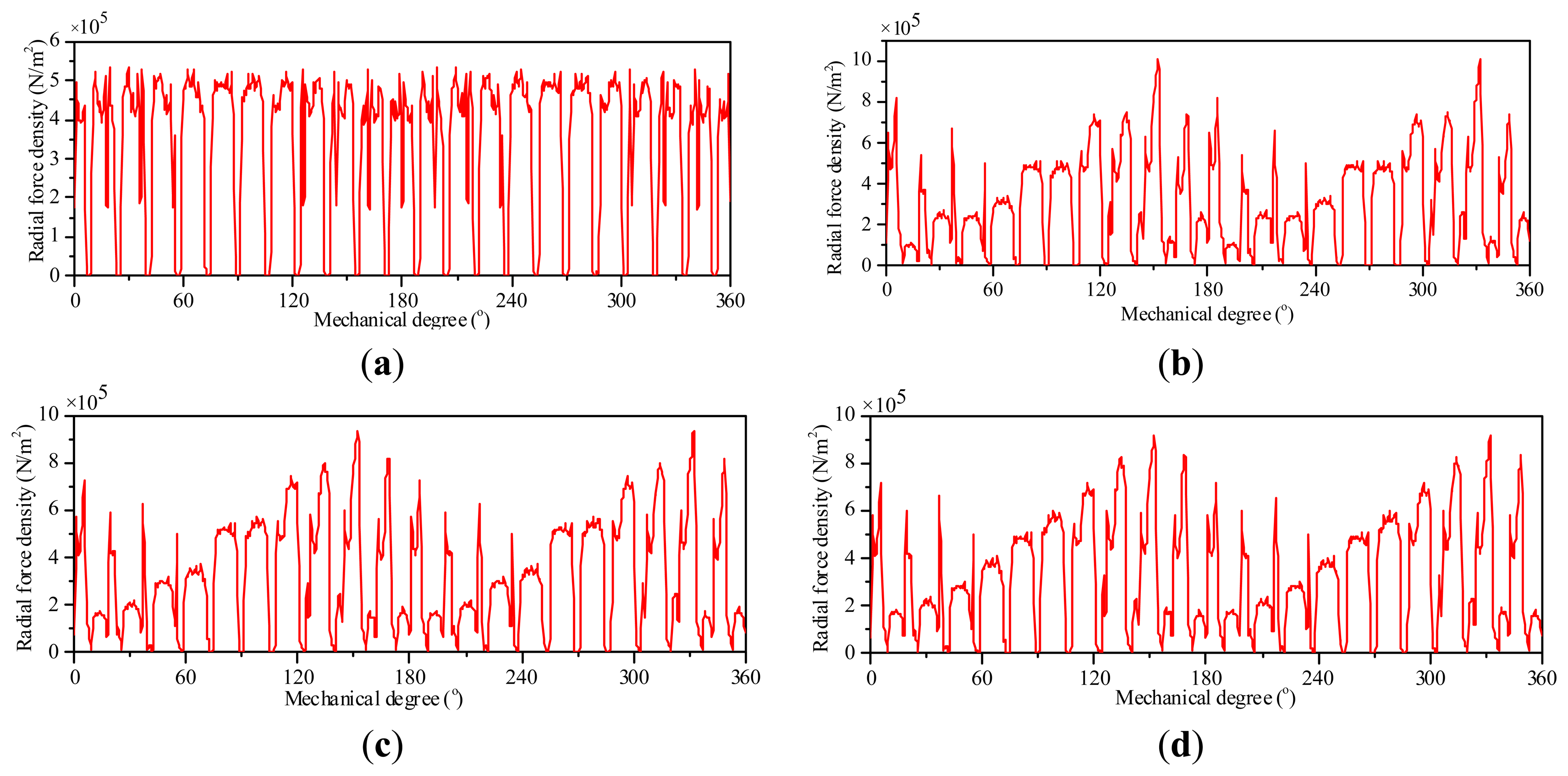
For the conventional and unequal-turn winding configurations, the radial force density distributions under both no-load and load conditions, and the corresponding harmonic analysis omitting the dc component are calculated, as shown in Figures 11 and 12. The no-load curves of conventional and unequal-turn winding configurations are the same. The radial force harmonic distribution in Figure 12b is normalized to the amplitude of the 22nd-order force harmonic in Figure 12a.
The no-load radial force density contains harmonics of orders 2, 20, 22, 44, etc., and the strongest 22nd and 44th order harmonics are consequences of the 11th working harmonic, i.e., the 22-pole PM field. For the conventional single- and double-layer windings, the dominant harmonics of load radial force density are with orders 2, 10, 12, 20, 22, 44, etc. Compared with the conventional single- and double-layer windings, the amplitudes of load radial force density harmonics of unequal-turn windings are lower, such as the 2nd, 10th, 12th and 20th order harmonics, etc. It is worth noting that the load radial force density contains a strong 2nd-order harmonic, and this strong harmonic can be clearly observed in Figure 11b–d. Since the machine structure is stiffer to short-wave distortion which corresponds to high order vibration mode, so the 2nd-order harmonic is the most detrimental to the machine strength, and compared with the conventional winding topologies, the 2nd-order harmonic of unequal-turn winding is reduced, which alleviates the harm of this harmonic.
4.5. Electromagnetic Performance Comparison of the Conventional and Unequal-Turn Windings
Three five-phase 20-slot/22-pole PMSM schemes featuring single-layer, double-layer and unequal-turn winding configurations have been designed and calculated using the commercial FEA software Ansoft Maxwell. For the three machine schemes, the stator lamination, efficient length, air gap length, width and thickness of magnet, and electromagnetic power are the same. Hence, direct electromagnetic performance comparison for the three schemes is possible. The magnet conductivity is σ = 625,000 s/m. In order to calculate the impact of skin effect on PM losses, high mesh density in magnets are adopted. Based on the 2-D FEA models, the PM losses are calculated without consideration of axial segmentation, circumferential segmentation, and 3D effect. The machine performances under the rated speed of 450 rpm are compared, as shown in Table 4.
All of the three winding configurations compared in Table 4 have smooth torques, which is beneficial to improve the driving comfort of EVs. Compared with the single-layer winding configuration, the core loss and PM loss of the double-layer winding configuration are reduced by 9.1% and 5.8%, and its efficiency is enhanced. By comparison with the double-layer winding configuration, the core loss and PM loss of the unequal-turn winding configuration are reduced by 1.8% and 4.2%, respectively. Among the three investigated schemes, the unequal-turn winding configuration has the highest efficiency, and it is more suitable for EV applications.
5. Open-Circuit Fault-Tolerant Control of the Unequal-Turn Winding Machine
As an electric drive system operates under some circumstances, over-voltage or over-current of the system will cause damage to the power electronic devices of converter, and it will lead to open-circuit faults of stator windings, then torque ripple increases and performance of the system degrades. Due to additional degrees of freedom, the five-phase PMSM can continue to work under open circuits of up to two phases without adding additional hardware and just by modifying the control strategy. In this section, a current control strategy that enables the five-phase unequal-turn winding PMSM to operate smoothly with loss of up to two phases is introduced.
5.1. One-Phase-Open Fault
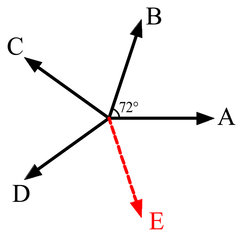
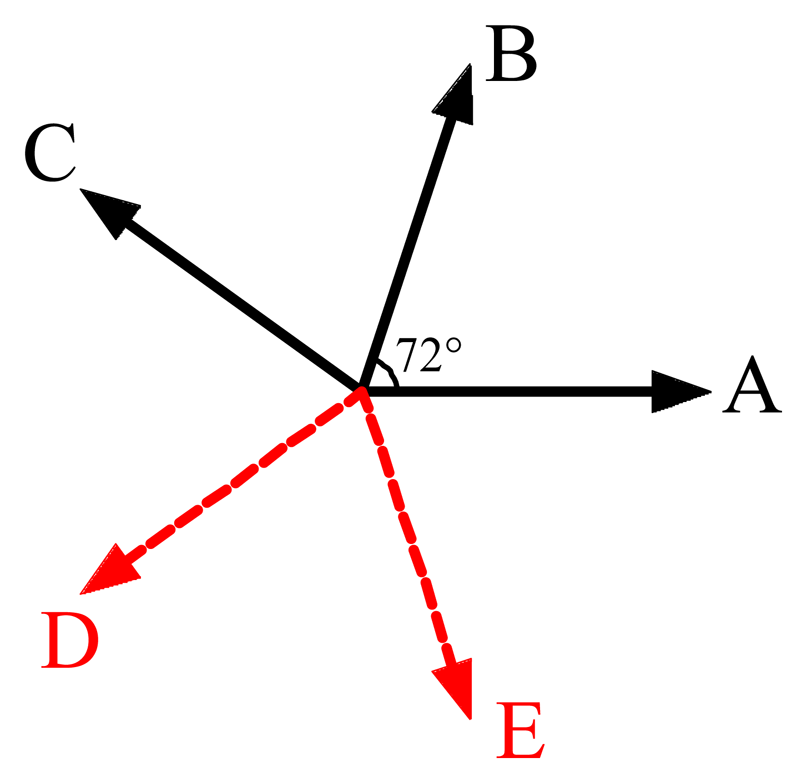
Assume Phase E is open-circuited, as shown in Figure 13.
The electromagnetic power of PMSM equals the sum of instantaneous power of each of the stator windings. The instantaneous power of each of the stator windings can be calculated by the phase current and the EMF induced in the windings. Through maintaining the sum of instantaneous power unchanged, the output electromagnetic power under open-circuit fault conditions can be the same as that under healthy conditions. For a certain speed, the output torque in open-circuit fault conditions can be kept the same as that before the fault happened. Under restrictive condition of keeping the output torque unchanged, the optimal currents for healthy phase windings can be calculated by minimizing a cost function of copper loss:
The problem dealt with open-circuit fault-tolerant control of the unequal-turn winding PMSM is transformed into a conditional extreme problem. Based on the Lagrange multiplier method, Equation (4) is obtained:
Through solving Equation (4), the optimal currents for healthy phase windings are obtained, as shown in Equation (5):
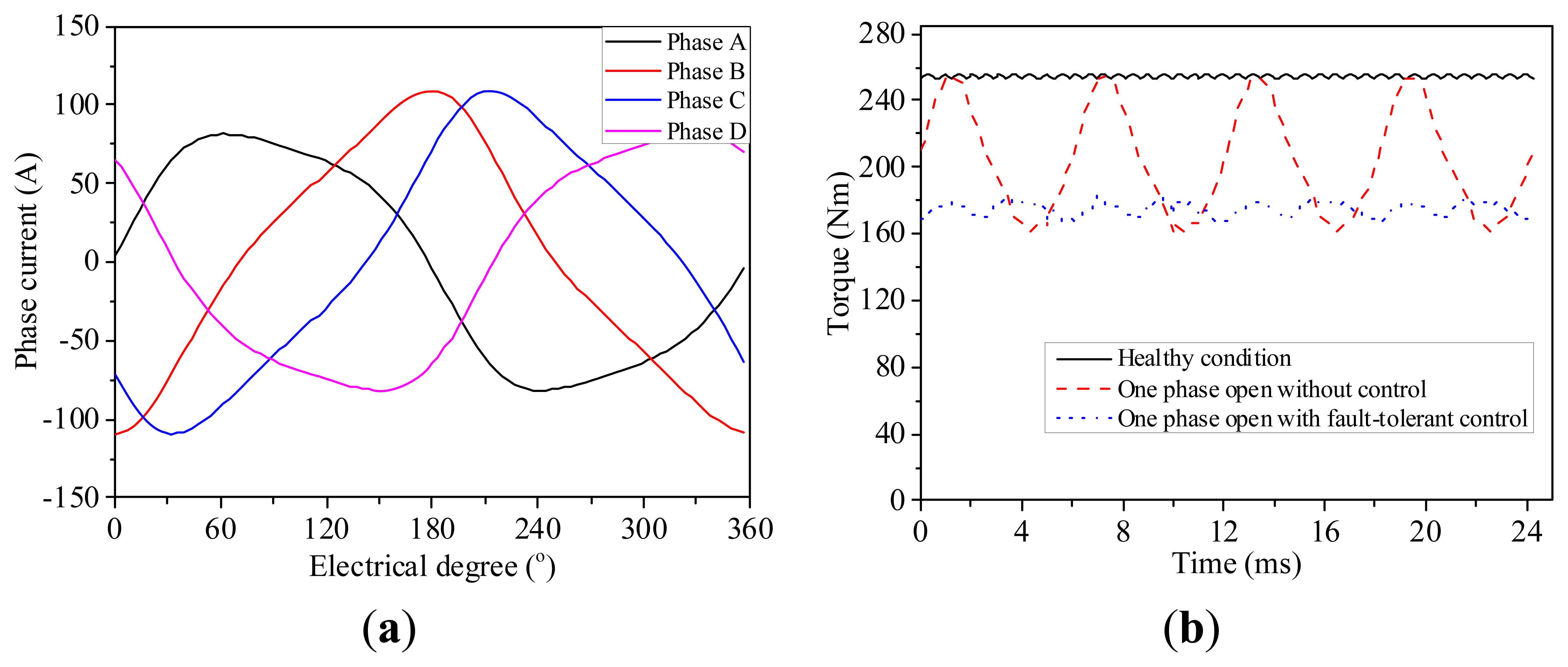
From Equation (5), we can find that the peak values of the calculated currents in fault conditions are larger than those in healthy conditions, which indicates an increased cost and converter capacity. For a five-phase fault-tolerant PMSM system used for EV applications, the operation under fault-conditions is an occasional case and small-probability event, and it is a waste to prevent occasional faults at the cost of increasing cost and converter capacity. Thus, in order not to improve the converter capacity, peak values of the calculated phase currents for healthy phase windings are scaled in the same proportion to achieve the same peak current values as the ones before faults happened. In fact, part of the output electromagnetic power is sacrificed. The currents for healthy phase windings and the torque performances are calculated and verified by FEA, as shown in Figure 14 and Table 5.
Under healthy conditions, the rated torque is 254.6N·m with a torque ripple of 0.44%. When Phase E is open-circuited, the output torque reduces to 80% of the rated torque, and the torque ripple dramatically increases to 23.38%, which is detrimental to the system performance. After adopting the proposed fault-tolerant control strategy, the machine efficiency improves slightly, the output torque decreases to 68.68% of the rated torque with a torque ripple of 4.22% and this will enable the EV applications to smoothly operate under reduced load conditions.
5.2. Two Adjacent-Phases-Open Fault
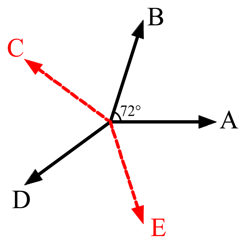
Assume Phases D and E are open-circuited, as shown in Figure 15.
Like the one-phase-open fault condition, the optimal currents for healthy phase windings can be calculated by minimizing a cost function of copper loss:
Through solving Equation (7), the optimal currents for healthy phase windings are obtained:
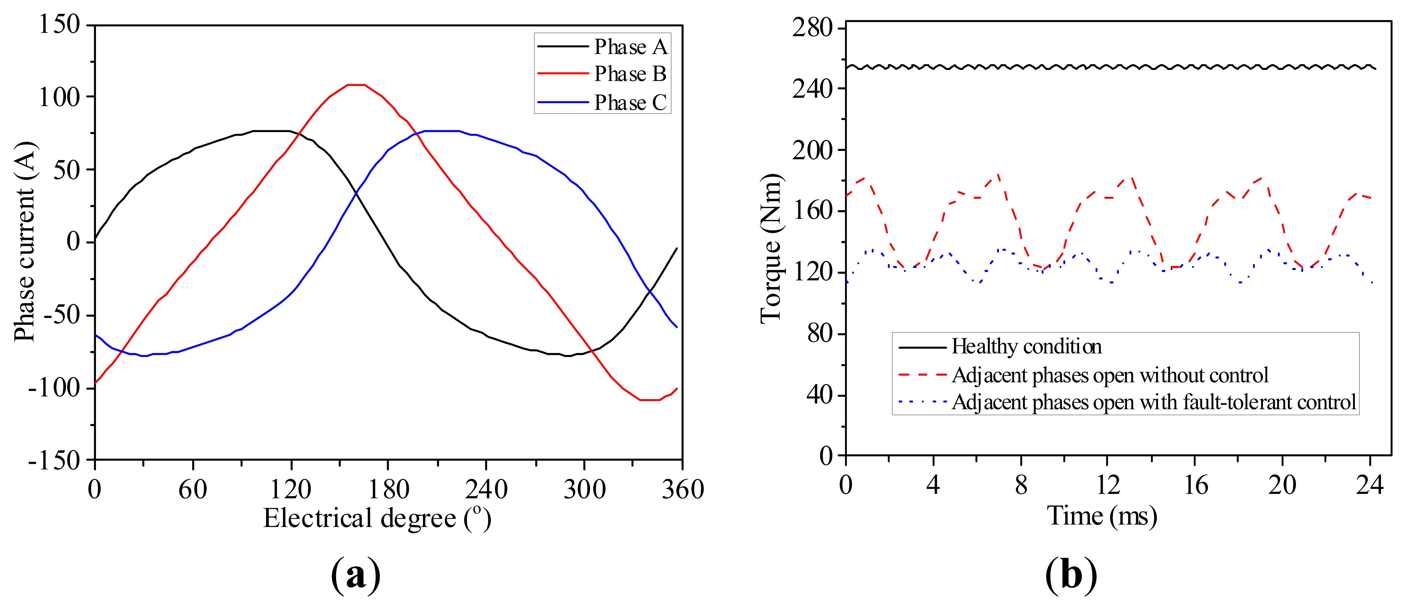
In this case, peak values of the calculated phase currents for healthy phase windings are also adjusted proportionally so that they can be the same as the ones before faults happened. The currents for healthy phase windings and the torque behaviors are calculated and verified by FEA, as shown in Figure 16 and Table 6.
As Phases D and E are open-circuited, the output torque reduces to 60.5% of the rated torque, and the torque ripple increases to 20.76%, which is detrimental to the system performance. After adopting the proposed fault-tolerant control strategy, the machine efficiency exceeds 95%, and the output torque further reduces to 49.28% of the rated torque with a torque ripple of 9.15%. In fact, part of the output electromagnetic power is sacrificed to obtain a smooth output torque, but the driving comfort of the EVs is significantly improved.
5.3. Two Non-Adjacent-Phases-Open Fault
Assume Phases C and E are open-circuited, as shown in Figure 17.
It is similar to the two adjacent-phases-open fault condition that the optimal currents for healthy phase windings can be calculated by minimizing a cost function of copper loss:
Through solving Equation (10), the optimal currents for healthy phase windings are obtained:
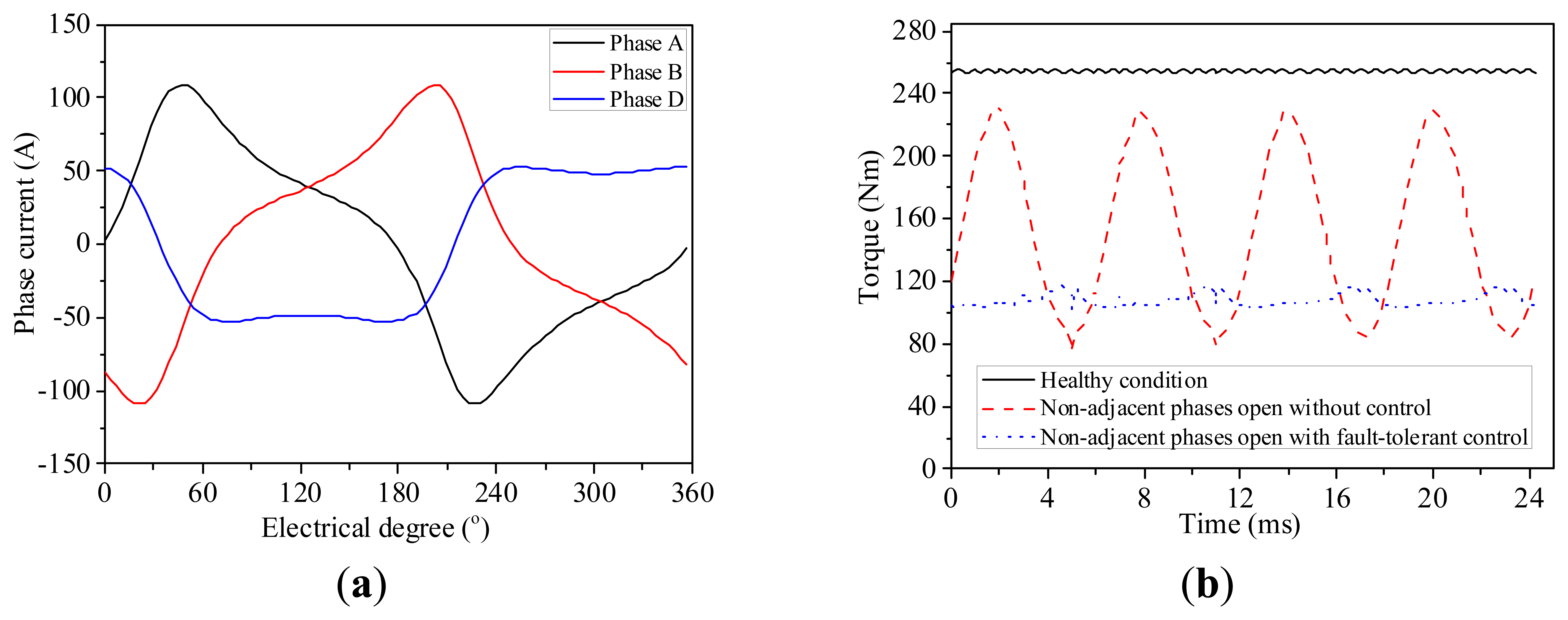
In this case, peak values of the calculated phase currents for healthy phase windings are also adjusted proportionally so that they can be the same as the ones before faults happened. The currents for healthy phase windings and the torque behaviors are calculated and verified by FEA, as shown in Figure 18 and Table 7.
As Phases C and E are open-circuited, the output torque reduces to 60.1% of the rated torque, and the torque ripple dramatically increases to 51.43%, which is detrimental to the system performance. After adopting the proposed fault-tolerant control strategy, the machine efficiency slightly decreases compared with the healthy condition, the output torque reduces to 42.46% of the rated torque, and it is 108.1N·m with a torque ripple of 6.86%, the torque ripple is significantly reduced, and this will enable the EV applications to smoothly operate under reduced load conditions. The comprehensive comparison of the machine performances under different operating conditions are listed, as shown in Table 8. The per unit values of Table 8 are shown in Table 9.
Since the electromagnetic power of PMSM equals the sum of instantaneous power of each of the stator windings, so when the machine operates under open-circuits of one or two phases, the output torques drop to 0.8 and 0.6 p.u., respectively, as shown in Tables 8 and 9. For one-phase-open, two adjacent-phases-open, and two non-adjacent-phases-open faults, after adoption of the proposed fault-tolerant control strategies, the torques decrease to 0.687, 0.493 and 0.425 p.u., respectively, but the torque ripples of all conditions are significantly reduced, and the machine efficiencies are even improved in some cases, which indicates that the proposed fault-tolerant control strategies are quite acceptable, with some sacrifice of the electromagnetic power.
6. Conclusions
- (1)
A five-phase 20-slot/22-pole PMSM featured with unequal-turn winding configuration is proposed for EV applications, and an improved slot-vector diagram is developed to calculate winding factors of different order harmonics for the unequal-turn winding configuration.
- (2)
The winding factor of 2-pole sub harmonic of double-layer winding is lower than that of single-layer winding. And for the unequal-turn winding, through optimization of the turn number of different coil sides, the winding factor of 2-pole sub harmonic is reduced to zero.
- (3)
The mutual inductances of double-layer winding configuration are larger than those of the single-layer winding configuration, and the mutual inductances of unequal-turn winding configuration are a little larger than those of the double-layer winding configuration, among the three investigated schemes, the unequal-turn winding scheme features least load radial force density harmonics, lowest PM loss and highest efficiency.
- (4)
The fault-tolerant control strategies for open-circuits of one and two phases are discussed. Under these control strategies, the torque ripples are significantly reduced, with some sacrifice of the electromagnetic power, and this will enable the EV applications to smoothly operate under reduced load conditions.
Acknowledgments
This work was supported in part by the 863 Plan of China under Project 2011AA11A261, and in part by National Natural Science Foundation of China under Projects 51077026, 51325701, and 51377033.
Conflicts of Interest
The authors declare no conflict of interest.
References
- EL-Refaie, A.M. Fractional-slot concentrated-windings synchronous permanent magnet machines: Opportunities and challenges. IEEE Trans. Ind. Electron. 2010, 57, 107–121. [Google Scholar]
- Wang, J.B.; Yuan, X.B.; Atallah, K. Design optimization of a surface-mounted permanent-magnet motor with concentrated windings for electric vehicle applications. IEEE Trans. Veh. Technol. 2013, 62, 1053–1064. [Google Scholar]
- Tangudu, J.K.; Jahns, T.M.; Bobn, T.P. Design, analysis and loss minimization of a fractional-slot concentrated winding IPM machine for traction applications. Proceedings of the 2011 IEEE Energy Conversion Congress and Exposition (ECCE), Phoenix, AZ, USA, 17–22 September 2011; pp. 2236–2243.
- Chen, Q.; Liu, G.H.; Gong, W.S.; Zhao, W.X. A new fault-tolerant permanent-magnet machine for electric vehicle applications. IEEE Trans. Magn. 2011, 47, 4183–4186. [Google Scholar]
- Parsa, L.; Toliyat, H. Fault-tolerant interior-permanent-magnet machines for hybrid electric vehicle applications. IEEE Trans. Veh. Technol. 2007, 56, 1546–1552. [Google Scholar]
- Reddy, P.B.; EL-Refaie, A.M.; Kum-Kang, H.; Tangudu, J.K.; Jahns, T.M. Comparison of interior and surface PM machines equipped with fractional-slot concentrated windings for hybrid traction applications. IEEE Trans. Energy Convers. 2012, 27, 593–602. [Google Scholar]
- Chung, S.U.; Kim, J.M.; Koo, D.H.; Woo, B.C.; Hong, D.K.; Lee, J.Y. Fractional slot concentrated winding permanent magnet synchronous machine with consequent pole rotor for low speed direct drive. IEEE Trans. Magn. 2012, 48, 2965–2968. [Google Scholar]
- Shah, M.R.; EL-Refaie, A.M. End Effects in Multiphase Fractional Slot Concentrated-winding surface permanent magnet synchronous machines. IEEE Trans. Energy Convers. 2010, 25, 1001–1009. [Google Scholar]
- Donato, G.D.; Capponi, F.G.; Caricchi, F. Fractional-slot concentrated-winding axial-flux permanent-magnet machine with core-wound coils. IEEE Trans. Ind. Appl. 2012, 48, 630–641. [Google Scholar]
- Barcaro, M.; Bianchi, N.; Magnussen, F. Remarks on torque estimation accuracy in fractional-slot permanent-magnet motors. IEEE Trans. Ind. Electron. 2012, 59, 2565–2572. [Google Scholar]
- El-Refaie, A.M. Fault-tolerant permanent magnet machines: A review. IET Electr. Power Appl. 2011, 5, 59–74. [Google Scholar]
- Merow, B.C.; Jack, A.G.; Atkinson, D.J.; Green, S.R.; Atkinson, G.J.; King, A.; Green, B. Design and testing of a four-phase fault-tolerant permanent-magnet machine for an engine fuel pump. IEEE Trans. Energy Convers. 2004, 19, 671–677. [Google Scholar]
- Bianchi, N.; Pre, M.D.; Bolognani, S. Design considerations on fractional-slot fault-tolerant synchronous motors. Proceedings of the IEEE International Conference on Electric Machines and Drives, San Antonio, TX, USA, 15–18 May 2005; pp. 902–909.
- Abolhassani, M.T.; Toliyat, H.A. Fault tolerant permanent magnet motor drives for electric vehicles. Proceedings of the IEEE International Electric Machines and Drives Conference, Miami, FL, USA,, 3–6 May 2009; pp. 1146–1152.
- Aslan, B.; Semail, E.; Korecki, J.; Legranger, J. Slot/pole combinations choice for concentrated multiphase machines dedicated to mild-hybrid applications. Proceedings of the 37th Annual Conference on IEEE Industrial Electronics Society (IECON 2011), Melbourne, Australia, 7–10 November 2011; pp. 3698–3703.
- Fornasiero, E.; Alberti, L.; Bianchi, N.; Bolognani, S. Considerations on selecting fractional-slot nonoverlapped coil windings. IEEE Trans. Ind. Appl. 2013, 49, 1316–1324. [Google Scholar]
- Bianchi, N.; Fornasiero, E. Impact of MMF space harmonic on rotor losses in fractional-slot permanent-magnet machines. IEEE Trans. Energy Convers. 2009, 24, 323–328. [Google Scholar]
- Bianchi, N.; Fornasiero, E. An index of rotor losses in three-phase fractional-slot permanent magnet machines. IET Electr. Power Appl. 2009, 3, 381–388. [Google Scholar]
- Aslan, B.; Semail, E.; Legranger, J. General analytical model of magnet average eddy-current volume losses for comparison of multiphase PM machines with concentrated winding. IEEE Trans. Energy Convers. 2014, 29, 72–83. [Google Scholar]
- Aslan, B.; Semail, E.; Legranger, J. Analytical model of magnet eddy-current volume losses in multi-phase PM machines with concentrated winding. Proceedings of the 2012 IEEE Energy Conversion Congress and Exposition (ECCE), Raleigh, NC, USA, 15–20 September 2012; pp. 3371–3378.
- Raminosoa, T.; Gerada, C.; Othman, N.; Lillo, L.D. Rotor losses in fault-tolerant permanent magnet synchronous machines. IET Electr. Power Appl. 2011, 5, 75–88. [Google Scholar]
- Fornasiero, E.; Bianchi, N.; Bolognani, S. Slot Harmonic impact on rotor losses in fractional-slot permanent-magnet machines. IEEE Trans. Ind. Appl. 2012, 59, 2557–2564. [Google Scholar]
- Wang, J.B.; Xia, Z.P.; Long, S.A.; Howe, D. Radial force density and vibration characteristics of modular permanent magnet brushless AC machine. IEE Proc. Electr. Power Appl. 2006, 153, 793–801. [Google Scholar]
- Wang, J.B.; Xia, Z.P.; Howe, D.; Long, S.A. Vibration characteristics of modular permanent magnet brushless AC machines. Proceedings of the 41st IEEE IAS Annual Meeting Conference, Tampa, FL, USA, 8–12 October 2006; pp. 1501–1506.
- Zhu, Z.Q.; Xia, Z.P.; Wu, L.J.; Jewell, G.W. Analytical modeling and finite-element computation of radial vibration force in fractional-slot permanent-magnet brushless machines. IEEE Trans. Ind. Appl. 2010, 46, 1908–1918. [Google Scholar]
- Zhu, Z.Q.; Xia, Z.P.; Wu, L.J.; Jewell, G.W. Influence of slot and pole number combination on radial force and vibration modes in fractional slot PM brushless machines having single- and double-layer windings. Proceedings of the IEEE Energy Conversion Congress and Exposition (ECCE), San Jose, CA, USA, 20–24 September 2009; pp. 3443–3450.
- Kometani, H.; Asao, Y.; Adachi, K. Dynamo-Electric Machine. U.S. Patent 6,166,471, 26 December 2000. [Google Scholar]
- Ito, K.; Naka, K.; Nakano, M.; Kobayashi, M. Electric Machine. U.S. Patent 7,605,514, 20 October 2009. [Google Scholar]
- Cistelecan, M.V.; Ferreira, F.J.T.E.; Popescu, M. Three phase tooth-concentrated multiple-layer fractional windings with low space harmonic content. Proceedings of the 2010 IEEE on Energy Conversion Congress and Exposition (ECCE), Atlanta, GA, USA, 12–16 September 2010; pp. 1399–1405.
- Dajaku, G.; Gerling, D. A novel 24-slots/10-poles winding topology for electric machines. Proceedings of the International Electric Machines and Drives Conference (IEMDC-2011), Niagara Falls, ON, Canada, 15–18 May 2011; pp. 65–70.
- Dajaku, G.; Gerling, D. Eddy current loss minimization in rotor magnets of PM machines using high-efficiency 12-teeth/10-slots winding topology. Proceedings of the International Conference on Electrical Machines and Systems 2011, Beijing, China, 20–23 August 2011; pp. 1–6.
- Staunton, R.H.; Ayers, C.W.; Marlino, L.D.; Chiasson, J.N.; Burress, T.A. Evaluation of 2004 Toyota Prius Hybrid Electric Drive System; Oak Ridge National Laboratory: Oak Ridge, TN, USA, 2006. [Google Scholar]
- Ifedi, C.J.; Mecrow, B.C.; Brockway, S.T.M.; Boast, G.S.; Atkinson, G.J.; Kostic-Perovic, D. Fault tolerant in-wheel motor topologies for high performance electric vehicles. Proceedings of the 2011 IEEE International Electric Machines & Drives Conference (IEMDC), Niagara Falls, ON, Canada, 15–18 May 2011; pp. 1310–1315.
- Ifedi, C.J.; Mecrow, B.C.; Widmer, J.D.; Atkinson, G.J.; Brockway, S.T.M.; Kostic-Perovic, D. A high torque density, direct drive in-wheel motor for electric vehicles. Proceedings of the 6th IET International Conference on Power Electronics, Machines and Drives (PEMD 2012), Bristol, UK, 27–29 March 2012; pp. 1–6.
- Rix, A.J.; Kamper, M.J. Radial-flux permanent-magnet hub drives: A comparison based on stator and rotor topologies. IEEE Trans. Ind. Electron. 2012, 59, 2475–2483. [Google Scholar]
- Zheng, P.; Sui, Y.; Zhao, J.; Tong, C.D.; Lipo, T.A.; Wang, A.M. Investigation of a novel five-phase modular permanent-magnet in-wheel motor. IEEE Trans. Magn. 2011, 47, 4084–4087. [Google Scholar]


| Parameter | 2004 Prius | Protean Electric | Radial-flux PM hub machine | Direct-drive machine |
|---|---|---|---|---|
| Peak output power (kW) | 50 | 80 | - | 24 |
| Continuous power (kW) | 30 | 54 | 10 | 12 |
| Base speed (rpm) | 1200 | 955 | 190 | 450 |
| Maximum speed (rpm) | 6000 | 1400 | 900 | 1200 |
| Number of stator slots | 48 | 72 | 30 | 20 |
| Number of poles | 8 | 64 | 40 | 22 |
| ν | Single layer | Double layer | Unequal-turn with N1/N2 = 19/20 | ||||||
|---|---|---|---|---|---|---|---|---|---|
| kwν | Bvm (mT) | p.u. | kwν | Bvm (mT) | p.u. | kwν | Bvm (mT) | p.u. | |
| 1 | 0.1564 | 5.3 | 1.56 | 0.0245 | 0.8 | 0.24 | 0.0005 | 0 | 0 |
| 9 | 0.9877 | 4.1 | 1.21 | 0.9755 | 4 | 1.21 | 0.9749 | 4 | 1.21 |
| 11 | 0.9877 | 3.4 | 1 | 0.9755 | 3.3 | 1 | 0.9749 | 3.3 | 1 |
Bvm is the amplitude of air-gap flux density (produced by windings).
| Windings layouts | LAA (mH) | MAB (mH) | MAC (mH) | MAD (mH) | MAE (mH) |
|---|---|---|---|---|---|
| Single-Layer | 1.782 | 0.004 | 0.013 | 0.013 | 0.004 |
| Double-Layer | 1.067 | 0 | 0.084 | 0.084 | 0 |
| Unequal-Turn | 1.092 | 0 | 0.091 | 0.091 | 0 |
| Winding layouts | Rated speed (rpm) | Frequency (Hz) | Torque (N·m) | Torque ripple (%) | Core loss (W) | PM loss (W) | Copper loss (W) | Efficiency (%) |
|---|---|---|---|---|---|---|---|---|
| Single-layer | 450 | 82.5 | 254.6 | 1.1 | 79.8 | 274.9 | 380 | 94.23 |
| Double-layer | 450 | 82.5 | 254.2 | 0.55 | 72.5 | 258.9 | 376.5 | 94.42 |
| Unequal-turn | 450 | 82.5 | 254.6 | 0.44 | 71.2 | 247.9 | 373.5 | 94.54 |
| Case | Rated Speed (rpm) | Torque (N·m) | Torque Ripple (%) | Core Loss (W) | PM Loss (W) | Copper Loss (W) | Efficiency (%) |
|---|---|---|---|---|---|---|---|
| Healthy | 450 | 254.6 | 0.44 | 71.2 | 247.9 | 373.5 | 94.54 |
| (a) | 450 | 204.2 | 23.38 | 68.1 | 196.3 | 298.8 | 94.47 |
| (b) | 450 | 174.8 | 4.22 | 64.3 | 153.6 | 217.3 | 94.98 |
Case (a)—Post-fault condition without control; Case (b)—Post-fault condition with fault-tolerant control.
| Case | Rated Speed (rpm) | Torque (N·m) | Torque Ripple (%) | Core Loss (W) | PM Loss (W) | Copper Loss (W) | Efficiency (%) |
|---|---|---|---|---|---|---|---|
| Healthy | 450 | 254.6 | 0.44 | 71.2 | 247.9 | 373.5 | 94.54 |
| (a) | 450 | 154.1 | 20.76 | 64.7 | 141.7 | 224.1 | 94.4 |
| (b) | 450 | 125.5 | 9.15 | 62.2 | 98.9 | 144.5 | 95.09 |
Case (a)—Post-fault condition without control; Case (b)—Post-fault condition with fault-tolerant control.
| Case | Rated Speed (rpm) | Torque (N·m) | Torque Ripple (%) | Core Loss (W) | PM Loss (W) | Copper Loss (W) | Efficiency (%) |
|---|---|---|---|---|---|---|---|
| Healthy | 450 | 254.6 | 0.44 | 71.2 | 247.9 | 373.5 | 94.54 |
| (a) | 450 | 153.1 | 51.43 | 64.6 | 148.8 | 224.1 | 94.32 |
| (b) | 450 | 108.1 | 6.86 | 65.2 | 117.8 | 122.2 | 94.35 |
Case (a)—Post-fault condition without control; Case (b)—Post-fault condition with fault-tolerant control.
| Case | Torque (Nm) | Torque ripple (%) | Efficiency (%) | |
|---|---|---|---|---|
| Healthy condition | 254.6 | 0.44 | 94.54 | |
| One-phase-open | (a) | 204.2 | 23.38 | 94.47 |
| (b) | 174.8 | 4.22 | 94.98 | |
| Adjacent-phases-open | (a) | 154.1 | 20.76 | 94.4 |
| (b) | 125.5 | 9.15 | 95.09 | |
| Non-adjacent-phases-open | (a) | 153.1 | 51.43 | 94.32 |
| (b) | 108.1 | 6.86 | 94.35 | |
Case (a)—Post-fault condition without control; Case (b)—Post-fault condition with fault-tolerant control.
| Case | Torque (p.u.) | Torque ripple (p.u.) | Efficiency (p.u.) | |
|---|---|---|---|---|
| Healthy condition | 1.0 | 1.0 | 1.0 | |
| One-phase-open | (a) | 0.802 | 53.14 | 0.999 |
| (b) | 0.687 | 9.59 | 1.005 | |
| Adjacent-phases-open | (a) | 0.605 | 47.18 | 0.999 |
| (b) | 0.493 | 20.8 | 1.006 | |
| Non-adjacent-phases-open | (a) | 0.601 | 116.89 | 0.998 |
| (b) | 0.425 | 15.59 | 0.998 | |
Case (a)—Post-fault condition without control; Case (b)—Post-fault condition with fault-tolerant control.
© 2014 by the authors; licensee MDPI, Basel, Switzerland. This article is an open access article distributed under the terms and conditions of the Creative Commons Attribution license ( http://creativecommons.org/licenses/by/3.0/).
Share and Cite
Sui, Y.; Zheng, P.; Wu, F.; Yu, B.; Wang, P.; Zhang, J. Research on a 20-Slot/22-Pole Five-Phase Fault-Tolerant PMSM Used for Four-Wheel-Drive Electric Vehicles. Energies 2014, 7, 1265-1287. https://doi.org/10.3390/en7031265
Sui Y, Zheng P, Wu F, Yu B, Wang P, Zhang J. Research on a 20-Slot/22-Pole Five-Phase Fault-Tolerant PMSM Used for Four-Wheel-Drive Electric Vehicles. Energies. 2014; 7(3):1265-1287. https://doi.org/10.3390/en7031265
Chicago/Turabian StyleSui, Yi, Ping Zheng, Fan Wu, Bin Yu, Pengfei Wang, and Jiawei Zhang. 2014. "Research on a 20-Slot/22-Pole Five-Phase Fault-Tolerant PMSM Used for Four-Wheel-Drive Electric Vehicles" Energies 7, no. 3: 1265-1287. https://doi.org/10.3390/en7031265